JP2014514374A - Microstructured tape - Google Patents
Microstructured tape Download PDFInfo
- Publication number
- JP2014514374A JP2014514374A JP2013557737A JP2013557737A JP2014514374A JP 2014514374 A JP2014514374 A JP 2014514374A JP 2013557737 A JP2013557737 A JP 2013557737A JP 2013557737 A JP2013557737 A JP 2013557737A JP 2014514374 A JP2014514374 A JP 2014514374A
- Authority
- JP
- Japan
- Prior art keywords
- support
- tape
- paint
- major
- weakness
- Prior art date
- Legal status (The legal status is an assumption and is not a legal conclusion. Google has not performed a legal analysis and makes no representation as to the accuracy of the status listed.)
- Pending
Links
Images


Classifications
-
- C—CHEMISTRY; METALLURGY
- C09—DYES; PAINTS; POLISHES; NATURAL RESINS; ADHESIVES; COMPOSITIONS NOT OTHERWISE PROVIDED FOR; APPLICATIONS OF MATERIALS NOT OTHERWISE PROVIDED FOR
- C09J—ADHESIVES; NON-MECHANICAL ASPECTS OF ADHESIVE PROCESSES IN GENERAL; ADHESIVE PROCESSES NOT PROVIDED FOR ELSEWHERE; USE OF MATERIALS AS ADHESIVES
- C09J7/00—Adhesives in the form of films or foils
- C09J7/20—Adhesives in the form of films or foils characterised by their carriers
- C09J7/22—Plastics; Metallised plastics
- C09J7/24—Plastics; Metallised plastics based on macromolecular compounds obtained by reactions involving only carbon-to-carbon unsaturated bonds
- C09J7/241—Polyolefin, e.g.rubber
- C09J7/243—Ethylene or propylene polymers
-
- C—CHEMISTRY; METALLURGY
- C09—DYES; PAINTS; POLISHES; NATURAL RESINS; ADHESIVES; COMPOSITIONS NOT OTHERWISE PROVIDED FOR; APPLICATIONS OF MATERIALS NOT OTHERWISE PROVIDED FOR
- C09J—ADHESIVES; NON-MECHANICAL ASPECTS OF ADHESIVE PROCESSES IN GENERAL; ADHESIVE PROCESSES NOT PROVIDED FOR ELSEWHERE; USE OF MATERIALS AS ADHESIVES
- C09J7/00—Adhesives in the form of films or foils
- C09J7/20—Adhesives in the form of films or foils characterised by their carriers
- C09J7/22—Plastics; Metallised plastics
-
- B—PERFORMING OPERATIONS; TRANSPORTING
- B05—SPRAYING OR ATOMISING IN GENERAL; APPLYING FLUENT MATERIALS TO SURFACES, IN GENERAL
- B05B—SPRAYING APPARATUS; ATOMISING APPARATUS; NOZZLES
- B05B12/00—Arrangements for controlling delivery; Arrangements for controlling the spray area
- B05B12/16—Arrangements for controlling delivery; Arrangements for controlling the spray area for controlling the spray area
- B05B12/20—Masking elements, i.e. elements defining uncoated areas on an object to be coated
- B05B12/24—Masking elements, i.e. elements defining uncoated areas on an object to be coated made at least partly of flexible material, e.g. sheets of paper or fabric
-
- B—PERFORMING OPERATIONS; TRANSPORTING
- B29—WORKING OF PLASTICS; WORKING OF SUBSTANCES IN A PLASTIC STATE IN GENERAL
- B29C—SHAPING OR JOINING OF PLASTICS; SHAPING OF MATERIAL IN A PLASTIC STATE, NOT OTHERWISE PROVIDED FOR; AFTER-TREATMENT OF THE SHAPED PRODUCTS, e.g. REPAIRING
- B29C48/00—Extrusion moulding, i.e. expressing the moulding material through a die or nozzle which imparts the desired form; Apparatus therefor
- B29C48/03—Extrusion moulding, i.e. expressing the moulding material through a die or nozzle which imparts the desired form; Apparatus therefor characterised by the shape of the extruded material at extrusion
- B29C48/07—Flat, e.g. panels
- B29C48/08—Flat, e.g. panels flexible, e.g. films
-
- B—PERFORMING OPERATIONS; TRANSPORTING
- B29—WORKING OF PLASTICS; WORKING OF SUBSTANCES IN A PLASTIC STATE IN GENERAL
- B29C—SHAPING OR JOINING OF PLASTICS; SHAPING OF MATERIAL IN A PLASTIC STATE, NOT OTHERWISE PROVIDED FOR; AFTER-TREATMENT OF THE SHAPED PRODUCTS, e.g. REPAIRING
- B29C48/00—Extrusion moulding, i.e. expressing the moulding material through a die or nozzle which imparts the desired form; Apparatus therefor
- B29C48/03—Extrusion moulding, i.e. expressing the moulding material through a die or nozzle which imparts the desired form; Apparatus therefor characterised by the shape of the extruded material at extrusion
- B29C48/12—Articles with an irregular circumference when viewed in cross-section, e.g. window profiles
-
- B—PERFORMING OPERATIONS; TRANSPORTING
- B29—WORKING OF PLASTICS; WORKING OF SUBSTANCES IN A PLASTIC STATE IN GENERAL
- B29C—SHAPING OR JOINING OF PLASTICS; SHAPING OF MATERIAL IN A PLASTIC STATE, NOT OTHERWISE PROVIDED FOR; AFTER-TREATMENT OF THE SHAPED PRODUCTS, e.g. REPAIRING
- B29C48/00—Extrusion moulding, i.e. expressing the moulding material through a die or nozzle which imparts the desired form; Apparatus therefor
- B29C48/03—Extrusion moulding, i.e. expressing the moulding material through a die or nozzle which imparts the desired form; Apparatus therefor characterised by the shape of the extruded material at extrusion
- B29C48/13—Articles with a cross-section varying in the longitudinal direction, e.g. corrugated pipes
-
- B—PERFORMING OPERATIONS; TRANSPORTING
- B29—WORKING OF PLASTICS; WORKING OF SUBSTANCES IN A PLASTIC STATE IN GENERAL
- B29C—SHAPING OR JOINING OF PLASTICS; SHAPING OF MATERIAL IN A PLASTIC STATE, NOT OTHERWISE PROVIDED FOR; AFTER-TREATMENT OF THE SHAPED PRODUCTS, e.g. REPAIRING
- B29C48/00—Extrusion moulding, i.e. expressing the moulding material through a die or nozzle which imparts the desired form; Apparatus therefor
- B29C48/25—Component parts, details or accessories; Auxiliary operations
- B29C48/88—Thermal treatment of the stream of extruded material, e.g. cooling
- B29C48/91—Heating, e.g. for cross linking
-
- B—PERFORMING OPERATIONS; TRANSPORTING
- B29—WORKING OF PLASTICS; WORKING OF SUBSTANCES IN A PLASTIC STATE IN GENERAL
- B29C—SHAPING OR JOINING OF PLASTICS; SHAPING OF MATERIAL IN A PLASTIC STATE, NOT OTHERWISE PROVIDED FOR; AFTER-TREATMENT OF THE SHAPED PRODUCTS, e.g. REPAIRING
- B29C48/00—Extrusion moulding, i.e. expressing the moulding material through a die or nozzle which imparts the desired form; Apparatus therefor
- B29C48/25—Component parts, details or accessories; Auxiliary operations
- B29C48/88—Thermal treatment of the stream of extruded material, e.g. cooling
- B29C48/911—Cooling
- B29C48/9135—Cooling of flat articles, e.g. using specially adapted supporting means
- B29C48/914—Cooling of flat articles, e.g. using specially adapted supporting means cooling drums
-
- B—PERFORMING OPERATIONS; TRANSPORTING
- B29—WORKING OF PLASTICS; WORKING OF SUBSTANCES IN A PLASTIC STATE IN GENERAL
- B29C—SHAPING OR JOINING OF PLASTICS; SHAPING OF MATERIAL IN A PLASTIC STATE, NOT OTHERWISE PROVIDED FOR; AFTER-TREATMENT OF THE SHAPED PRODUCTS, e.g. REPAIRING
- B29C48/00—Extrusion moulding, i.e. expressing the moulding material through a die or nozzle which imparts the desired form; Apparatus therefor
- B29C48/25—Component parts, details or accessories; Auxiliary operations
- B29C48/88—Thermal treatment of the stream of extruded material, e.g. cooling
- B29C48/911—Cooling
- B29C48/9135—Cooling of flat articles, e.g. using specially adapted supporting means
- B29C48/915—Cooling of flat articles, e.g. using specially adapted supporting means with means for improving the adhesion to the supporting means
- B29C48/9155—Pressure rollers
-
- B—PERFORMING OPERATIONS; TRANSPORTING
- B32—LAYERED PRODUCTS
- B32B—LAYERED PRODUCTS, i.e. PRODUCTS BUILT-UP OF STRATA OF FLAT OR NON-FLAT, e.g. CELLULAR OR HONEYCOMB, FORM
- B32B3/00—Layered products comprising a layer with external or internal discontinuities or unevennesses, or a layer of non-planar form; Layered products having particular features of form
- B32B3/26—Layered products comprising a layer with external or internal discontinuities or unevennesses, or a layer of non-planar form; Layered products having particular features of form characterised by a particular shape of the outline of the cross-section of a continuous layer; characterised by a layer with cavities or internal voids ; characterised by an apertured layer
- B32B3/30—Layered products comprising a layer with external or internal discontinuities or unevennesses, or a layer of non-planar form; Layered products having particular features of form characterised by a particular shape of the outline of the cross-section of a continuous layer; characterised by a layer with cavities or internal voids ; characterised by an apertured layer characterised by a layer formed with recesses or projections, e.g. hollows, grooves, protuberances, ribs
-
- B—PERFORMING OPERATIONS; TRANSPORTING
- B32—LAYERED PRODUCTS
- B32B—LAYERED PRODUCTS, i.e. PRODUCTS BUILT-UP OF STRATA OF FLAT OR NON-FLAT, e.g. CELLULAR OR HONEYCOMB, FORM
- B32B38/00—Ancillary operations in connection with laminating processes
- B32B38/06—Embossing
-
- B—PERFORMING OPERATIONS; TRANSPORTING
- B32—LAYERED PRODUCTS
- B32B—LAYERED PRODUCTS, i.e. PRODUCTS BUILT-UP OF STRATA OF FLAT OR NON-FLAT, e.g. CELLULAR OR HONEYCOMB, FORM
- B32B5/00—Layered products characterised by the non- homogeneity or physical structure, i.e. comprising a fibrous, filamentary, particulate or foam layer; Layered products characterised by having a layer differing constitutionally or physically in different parts
- B32B5/02—Layered products characterised by the non- homogeneity or physical structure, i.e. comprising a fibrous, filamentary, particulate or foam layer; Layered products characterised by having a layer differing constitutionally or physically in different parts characterised by structural features of a fibrous or filamentary layer
- B32B5/08—Layered products characterised by the non- homogeneity or physical structure, i.e. comprising a fibrous, filamentary, particulate or foam layer; Layered products characterised by having a layer differing constitutionally or physically in different parts characterised by structural features of a fibrous or filamentary layer the fibres or filaments of a layer being of different substances, e.g. conjugate fibres, mixture of different fibres
-
- B—PERFORMING OPERATIONS; TRANSPORTING
- B32—LAYERED PRODUCTS
- B32B—LAYERED PRODUCTS, i.e. PRODUCTS BUILT-UP OF STRATA OF FLAT OR NON-FLAT, e.g. CELLULAR OR HONEYCOMB, FORM
- B32B7/00—Layered products characterised by the relation between layers; Layered products characterised by the relative orientation of features between layers, or by the relative values of a measurable parameter between layers, i.e. products comprising layers having different physical, chemical or physicochemical properties; Layered products characterised by the interconnection of layers
- B32B7/04—Interconnection of layers
- B32B7/12—Interconnection of layers using interposed adhesives or interposed materials with bonding properties
-
- C—CHEMISTRY; METALLURGY
- C09—DYES; PAINTS; POLISHES; NATURAL RESINS; ADHESIVES; COMPOSITIONS NOT OTHERWISE PROVIDED FOR; APPLICATIONS OF MATERIALS NOT OTHERWISE PROVIDED FOR
- C09J—ADHESIVES; NON-MECHANICAL ASPECTS OF ADHESIVE PROCESSES IN GENERAL; ADHESIVE PROCESSES NOT PROVIDED FOR ELSEWHERE; USE OF MATERIALS AS ADHESIVES
- C09J7/00—Adhesives in the form of films or foils
- C09J7/20—Adhesives in the form of films or foils characterised by their carriers
- C09J7/203—Adhesives in the form of films or foils characterised by their carriers characterised by the structure of the release feature on the carrier layer
-
- B—PERFORMING OPERATIONS; TRANSPORTING
- B29—WORKING OF PLASTICS; WORKING OF SUBSTANCES IN A PLASTIC STATE IN GENERAL
- B29C—SHAPING OR JOINING OF PLASTICS; SHAPING OF MATERIAL IN A PLASTIC STATE, NOT OTHERWISE PROVIDED FOR; AFTER-TREATMENT OF THE SHAPED PRODUCTS, e.g. REPAIRING
- B29C48/00—Extrusion moulding, i.e. expressing the moulding material through a die or nozzle which imparts the desired form; Apparatus therefor
- B29C48/001—Combinations of extrusion moulding with other shaping operations
- B29C48/0011—Combinations of extrusion moulding with other shaping operations combined with compression moulding
-
- B—PERFORMING OPERATIONS; TRANSPORTING
- B29—WORKING OF PLASTICS; WORKING OF SUBSTANCES IN A PLASTIC STATE IN GENERAL
- B29C—SHAPING OR JOINING OF PLASTICS; SHAPING OF MATERIAL IN A PLASTIC STATE, NOT OTHERWISE PROVIDED FOR; AFTER-TREATMENT OF THE SHAPED PRODUCTS, e.g. REPAIRING
- B29C48/00—Extrusion moulding, i.e. expressing the moulding material through a die or nozzle which imparts the desired form; Apparatus therefor
- B29C48/001—Combinations of extrusion moulding with other shaping operations
- B29C48/0021—Combinations of extrusion moulding with other shaping operations combined with joining, lining or laminating
-
- B—PERFORMING OPERATIONS; TRANSPORTING
- B29—WORKING OF PLASTICS; WORKING OF SUBSTANCES IN A PLASTIC STATE IN GENERAL
- B29C—SHAPING OR JOINING OF PLASTICS; SHAPING OF MATERIAL IN A PLASTIC STATE, NOT OTHERWISE PROVIDED FOR; AFTER-TREATMENT OF THE SHAPED PRODUCTS, e.g. REPAIRING
- B29C48/00—Extrusion moulding, i.e. expressing the moulding material through a die or nozzle which imparts the desired form; Apparatus therefor
- B29C48/15—Extrusion moulding, i.e. expressing the moulding material through a die or nozzle which imparts the desired form; Apparatus therefor incorporating preformed parts or layers, e.g. extrusion moulding around inserts
- B29C48/154—Coating solid articles, i.e. non-hollow articles
- B29C48/155—Partial coating thereof
-
- B—PERFORMING OPERATIONS; TRANSPORTING
- B32—LAYERED PRODUCTS
- B32B—LAYERED PRODUCTS, i.e. PRODUCTS BUILT-UP OF STRATA OF FLAT OR NON-FLAT, e.g. CELLULAR OR HONEYCOMB, FORM
- B32B2309/00—Parameters for the laminating or treatment process; Apparatus details
- B32B2309/08—Dimensions, e.g. volume
-
- B—PERFORMING OPERATIONS; TRANSPORTING
- B32—LAYERED PRODUCTS
- B32B—LAYERED PRODUCTS, i.e. PRODUCTS BUILT-UP OF STRATA OF FLAT OR NON-FLAT, e.g. CELLULAR OR HONEYCOMB, FORM
- B32B2309/00—Parameters for the laminating or treatment process; Apparatus details
- B32B2309/14—Velocity, e.g. feed speeds
-
- B—PERFORMING OPERATIONS; TRANSPORTING
- B32—LAYERED PRODUCTS
- B32B—LAYERED PRODUCTS, i.e. PRODUCTS BUILT-UP OF STRATA OF FLAT OR NON-FLAT, e.g. CELLULAR OR HONEYCOMB, FORM
- B32B2405/00—Adhesive articles, e.g. adhesive tapes
-
- B—PERFORMING OPERATIONS; TRANSPORTING
- B32—LAYERED PRODUCTS
- B32B—LAYERED PRODUCTS, i.e. PRODUCTS BUILT-UP OF STRATA OF FLAT OR NON-FLAT, e.g. CELLULAR OR HONEYCOMB, FORM
- B32B37/00—Methods or apparatus for laminating, e.g. by curing or by ultrasonic bonding
- B32B37/14—Methods or apparatus for laminating, e.g. by curing or by ultrasonic bonding characterised by the properties of the layers
- B32B37/16—Methods or apparatus for laminating, e.g. by curing or by ultrasonic bonding characterised by the properties of the layers with all layers existing as coherent layers before laminating
- B32B37/20—Methods or apparatus for laminating, e.g. by curing or by ultrasonic bonding characterised by the properties of the layers with all layers existing as coherent layers before laminating involving the assembly of continuous webs only
- B32B37/203—One or more of the layers being plastic
-
- C—CHEMISTRY; METALLURGY
- C09—DYES; PAINTS; POLISHES; NATURAL RESINS; ADHESIVES; COMPOSITIONS NOT OTHERWISE PROVIDED FOR; APPLICATIONS OF MATERIALS NOT OTHERWISE PROVIDED FOR
- C09J—ADHESIVES; NON-MECHANICAL ASPECTS OF ADHESIVE PROCESSES IN GENERAL; ADHESIVE PROCESSES NOT PROVIDED FOR ELSEWHERE; USE OF MATERIALS AS ADHESIVES
- C09J2203/00—Applications of adhesives in processes or use of adhesives in the form of films or foils
- C09J2203/31—Applications of adhesives in processes or use of adhesives in the form of films or foils as a masking tape for painting
-
- C—CHEMISTRY; METALLURGY
- C09—DYES; PAINTS; POLISHES; NATURAL RESINS; ADHESIVES; COMPOSITIONS NOT OTHERWISE PROVIDED FOR; APPLICATIONS OF MATERIALS NOT OTHERWISE PROVIDED FOR
- C09J—ADHESIVES; NON-MECHANICAL ASPECTS OF ADHESIVE PROCESSES IN GENERAL; ADHESIVE PROCESSES NOT PROVIDED FOR ELSEWHERE; USE OF MATERIALS AS ADHESIVES
- C09J2301/00—Additional features of adhesives in the form of films or foils
- C09J2301/10—Additional features of adhesives in the form of films or foils characterized by the structural features of the adhesive tape or sheet
- C09J2301/16—Additional features of adhesives in the form of films or foils characterized by the structural features of the adhesive tape or sheet by the structure of the carrier layer
-
- C—CHEMISTRY; METALLURGY
- C09—DYES; PAINTS; POLISHES; NATURAL RESINS; ADHESIVES; COMPOSITIONS NOT OTHERWISE PROVIDED FOR; APPLICATIONS OF MATERIALS NOT OTHERWISE PROVIDED FOR
- C09J—ADHESIVES; NON-MECHANICAL ASPECTS OF ADHESIVE PROCESSES IN GENERAL; ADHESIVE PROCESSES NOT PROVIDED FOR ELSEWHERE; USE OF MATERIALS AS ADHESIVES
- C09J2301/00—Additional features of adhesives in the form of films or foils
- C09J2301/20—Additional features of adhesives in the form of films or foils characterized by the structural features of the adhesive itself
- C09J2301/204—Additional features of adhesives in the form of films or foils characterized by the structural features of the adhesive itself the adhesive coating being discontinuous
-
- C—CHEMISTRY; METALLURGY
- C09—DYES; PAINTS; POLISHES; NATURAL RESINS; ADHESIVES; COMPOSITIONS NOT OTHERWISE PROVIDED FOR; APPLICATIONS OF MATERIALS NOT OTHERWISE PROVIDED FOR
- C09J—ADHESIVES; NON-MECHANICAL ASPECTS OF ADHESIVE PROCESSES IN GENERAL; ADHESIVE PROCESSES NOT PROVIDED FOR ELSEWHERE; USE OF MATERIALS AS ADHESIVES
- C09J2301/00—Additional features of adhesives in the form of films or foils
- C09J2301/30—Additional features of adhesives in the form of films or foils characterized by the chemical, physicochemical or physical properties of the adhesive or the carrier
- C09J2301/302—Additional features of adhesives in the form of films or foils characterized by the chemical, physicochemical or physical properties of the adhesive or the carrier the adhesive being pressure-sensitive, i.e. tacky at temperatures inferior to 30°C
-
- Y—GENERAL TAGGING OF NEW TECHNOLOGICAL DEVELOPMENTS; GENERAL TAGGING OF CROSS-SECTIONAL TECHNOLOGIES SPANNING OVER SEVERAL SECTIONS OF THE IPC; TECHNICAL SUBJECTS COVERED BY FORMER USPC CROSS-REFERENCE ART COLLECTIONS [XRACs] AND DIGESTS
- Y10—TECHNICAL SUBJECTS COVERED BY FORMER USPC
- Y10T—TECHNICAL SUBJECTS COVERED BY FORMER US CLASSIFICATION
- Y10T428/00—Stock material or miscellaneous articles
- Y10T428/14—Layer or component removable to expose adhesive
- Y10T428/1486—Ornamental, decorative, pattern, or indicia
-
- Y—GENERAL TAGGING OF NEW TECHNOLOGICAL DEVELOPMENTS; GENERAL TAGGING OF CROSS-SECTIONAL TECHNOLOGIES SPANNING OVER SEVERAL SECTIONS OF THE IPC; TECHNICAL SUBJECTS COVERED BY FORMER USPC CROSS-REFERENCE ART COLLECTIONS [XRACs] AND DIGESTS
- Y10—TECHNICAL SUBJECTS COVERED BY FORMER USPC
- Y10T—TECHNICAL SUBJECTS COVERED BY FORMER US CLASSIFICATION
- Y10T428/00—Stock material or miscellaneous articles
- Y10T428/15—Sheet, web, or layer weakened to permit separation through thickness
-
- Y—GENERAL TAGGING OF NEW TECHNOLOGICAL DEVELOPMENTS; GENERAL TAGGING OF CROSS-SECTIONAL TECHNOLOGIES SPANNING OVER SEVERAL SECTIONS OF THE IPC; TECHNICAL SUBJECTS COVERED BY FORMER USPC CROSS-REFERENCE ART COLLECTIONS [XRACs] AND DIGESTS
- Y10—TECHNICAL SUBJECTS COVERED BY FORMER USPC
- Y10T—TECHNICAL SUBJECTS COVERED BY FORMER US CLASSIFICATION
- Y10T428/00—Stock material or miscellaneous articles
- Y10T428/24—Structurally defined web or sheet [e.g., overall dimension, etc.]
- Y10T428/24479—Structurally defined web or sheet [e.g., overall dimension, etc.] including variation in thickness
- Y10T428/2457—Parallel ribs and/or grooves
-
- Y—GENERAL TAGGING OF NEW TECHNOLOGICAL DEVELOPMENTS; GENERAL TAGGING OF CROSS-SECTIONAL TECHNOLOGIES SPANNING OVER SEVERAL SECTIONS OF THE IPC; TECHNICAL SUBJECTS COVERED BY FORMER USPC CROSS-REFERENCE ART COLLECTIONS [XRACs] AND DIGESTS
- Y10—TECHNICAL SUBJECTS COVERED BY FORMER USPC
- Y10T—TECHNICAL SUBJECTS COVERED BY FORMER US CLASSIFICATION
- Y10T428/00—Stock material or miscellaneous articles
- Y10T428/28—Web or sheet containing structurally defined element or component and having an adhesive outermost layer
- Y10T428/2848—Three or more layers
Abstract
塗料保持微細構造パターンを含む第1の主面と、手引き裂き微細構造パターンを含み得る第2の主面と、を有する支持体を含み、感圧接着層が支持体の第2の主面に配置される、プラスチックテープであって、支持体、塗料保持微細構造パターン、及び手引き裂き微細構造パターン(存在する場合)が全体で一体構造のプラスチックユニットを構成するプラスチックテープが本明細書において開示される。
【選択図】図1A support having a first major surface including a paint-holding microstructure pattern and a second major surface that may include a hand-tear microstructure pattern, wherein the pressure sensitive adhesive layer is on the second major surface of the support Disclosed herein is a plastic tape, wherein the support, the paint-holding microstructure pattern, and the hand-tearing microstructure pattern (if present) together constitute a unitary plastic unit. The
[Selection] Figure 1
Description
マスキングテープは、表面を塗装する際に以前から使用されている。マスキングテープは、多くの場合、片面に感圧接着剤を有するクレープ紙からなる。 Masking tape has long been used when painting surfaces. Masking tapes often consist of crepe paper with a pressure sensitive adhesive on one side.
塗料保持微細構造パターンを含む第1の主面と、手引き裂き微細構造パターンを含み得る第2の主面と、を有する支持体を含み、感圧接着層が支持体の第2の主面に配置されるプラスチックテープであって、支持体、塗料保持微細構造パターン、及び手引き裂き微細構造パターン(存在する場合)が全体で一体構造のプラスチックユニットを構成するプラスチプが本明細書において開示される。 A support having a first major surface including a paint-holding microstructure pattern and a second major surface that may include a hand-tear microstructure pattern, wherein the pressure sensitive adhesive layer is on the second major surface of the support Disclosed herein is a plastic tape that is disposed, wherein the support, the paint-holding microstructure pattern, and the hand-tear microstructure pattern (if present) together constitute a unitary plastic unit.
手引き裂き可能なプラスチックテープであって、支持体を含み、支持体が、長手方向軸、短手方向の幅及び軸、第1の主面、及び相対して面する第2の主面を含み、支持体の第1の主面が、微小容器を含む塗料保持微細構造パターンを含み、微小容器が、複数の第1の微細構造隔壁及び複数の第2の微細構造隔壁によって少なくとも部分的に画定され、複数の第2の微細構造隔壁の少なくともいくつかが第1の微細構造隔壁と交差し、それによって微小容器を画定し、支持体の第2の主面が、複数の脆弱線を含む手引き裂き微細構造パターンを含み、複数の脆弱線の少なくともいくつかが、支持体に対して少なくとも略短手方向に配向される長軸を含み、支持体の第2の主面に感圧接着剤が配置され、支持体、塗料保持微細構造パターン、及び手引き裂き微細構造パターンが全体で一体構造のプラスチックユニットを構成する、手引き裂き可能なプラスチックテープを開示する。 A hand tearable plastic tape comprising a support, the support comprising a longitudinal axis, a transverse width and axis, a first major surface and a second major surface facing oppositely The first major surface of the support includes a paint-holding microstructure pattern including a microcontainer, the microcontainer being at least partially defined by a plurality of first microstructured partitions and a plurality of second microstructured partitions. And at least some of the plurality of second microstructured partitions intersect the first microstructured partition, thereby defining a microcontainer, wherein the second major surface of the support includes a plurality of weak lines. Including a tearing microstructure pattern, wherein at least some of the plurality of lines of weakness include a major axis oriented at least generally transverse to the support, and a pressure sensitive adhesive is disposed on the second major surface of the support. Arranged, support, paint-holding microstructure pattern, and Hand constituting the plastic unit monolithic across tear microstructured pattern, discloses a hand tearable plastic tape.
第2の表面部分を塗装しないようにマスキングした状態で第1の表面部分を塗装する方法であって、所与の長さの手引き裂き可能なプラスチックテープを第2の表面部分に接着により取り付ける工程であって、プラスチックテープが、長手方向軸と短手方向の幅及び軸、第1の主面、及び相対して面する第2の主面を含む支持体を含み、支持体の第1の主面が塗料保持微細構造パターンを含み、支持体の前記第2の主面が手引き裂き微細構造パターンを含み、支持体の第2の主面に感圧接着剤が配置され、支持体、塗料保持微細構造パターン、及び手引き裂き微細構造パターンが全体で一体構造のプラスチックユニットを構成する、取り付ける工程と、少なくとも第1の表面部分に液体塗料を塗布する工程と、を含む方法を開示する。 A method of coating a first surface portion in a state where the second surface portion is masked so as not to be painted, and a step of attaching a tearable plastic tape of a given length to the second surface portion by adhesion The plastic tape includes a support including a longitudinal axis and a transverse width and axis, a first major surface, and a second major surface facing oppositely, the first of the supports The main surface includes a paint-holding fine structure pattern, the second main surface of the support includes a hand tearing fine structure pattern, and a pressure sensitive adhesive is disposed on the second main surface of the support. Disclosed is a method comprising the steps of attaching, and applying a liquid paint to at least a first surface portion, wherein the holding microstructure structure and the hand tear microstructure structure together constitute a unitary plastic unit.
塗料保持微細構造パターンを有する第1の主面と、手引き裂き微細構造パターンを有する第2の相対して面する主面とを有する支持体を含む手引き裂き可能なプラスチックテープの製造方法であって、溶融ポリマー押出品の第1の主表面を、塗料保持微細構造パターンのネガ型を含む第1の成形面と接触させ、かつ、溶融ポリマー押出品の第2の主表面を、手引き裂き微細構造パターンのネガ型を含む第2の成形面と接触させる工程であって、溶融ポリマー押出品の第1の主表面が第1の成形型に接して成形され、溶融ポリマー押出品の第2の主表面が第2の成形型に接して成形され、それによって支持体の第1の主面に塗料保持微細構造パターンを有し、かつ支持体の前記第2の主面に手引き裂き微細構造パターンを有する支持体を形成する、接触させる工程と、支持体の第2の主面に感圧接着剤を配置する工程と、を含む方法を開示する。 A method for producing a hand tearable plastic tape comprising a support having a first major surface having a paint retaining microstructure pattern and a second oppositely facing major surface having a hand tear microstructure pattern. The first main surface of the molten polymer extrudate is brought into contact with the first molding surface including a negative mold of the paint holding microstructure structure, and the second main surface of the molten polymer extrudate is hand-teared microstructure Contacting a second molding surface comprising a pattern negative mold, wherein the first major surface of the molten polymer extrudate is molded against the first mold and the second major surface of the molten polymer extrudate is The surface is molded in contact with the second mold, thereby having a paint holding microstructure pattern on the first main surface of the support and a hand tearing microstructure pattern on the second main surface of the support. Form a support with Discloses a step of contacting, a step of arranging a pressure sensitive adhesive on the second major surface of the support, the method comprising.
本発明のこれらの態様及び他の態様は、以下の詳細な説明より明らかになるであろう。しかしながら、上記の概要は、いかなる場合においても特許請求される主題に対する限定として解釈されるべきではなく、手続において補正され得る添付の特許請求の範囲によってのみ定義されるものである。 These and other aspects of the invention will be apparent from the detailed description below. However, the above summary should not be construed as limiting the claimed subject matter in any way, but should be defined only by the appended claims, which may be amended in proceedings.
異なる図面における同様の参照番号は同様の要素を示す。要素によっては、同じ又は同等のものが複数存在するものがあり、その場合、1以上の代表的な要素のみが参照符合によって示されている場合があるが、こうした参照符合は全てのこのような同じ要素に適用されるものであることは理解されるであろう。特に断らない限り、本文書の図面はいずれも一定の縮尺ではなく、本発明の異なる実施形態を例示する目的で選択されたものである。詳細には、異なる要素の寸法はあくまで例示的な意味で示されるものであり、特にそのように断られない限り、図面から異なる要素の寸法間にいっさいの関係が推測されるべきではない。「上部」、「下部」、「上側」、「下側」、「下」、「上」、「前」、「後」、「上方」、「下方」、並びに「第1」及び「第2」などの用語が本開示に使用され得るが、特に断らない限り、これらの用語はあくまで相対的な意味においてのみ使用される点を理解すべきである。用語「外側に向けて」及び「内側に向けて」は、それぞれ、概ねテープ1の支持体2の内部から離れる方向、及びテープ1の支持体2の内部に向う方向を指す。
Like reference numbers in different drawings indicate like elements. Some elements may have the same or equivalent, in which case only one or more representative elements may be indicated by reference signs, but such reference signs may be used for all such elements. It will be understood that it applies to the same elements. Unless otherwise indicated, all drawings in this document are not to scale and are selected for the purpose of illustrating different embodiments of the invention. In particular, the dimensions of the different elements are shown by way of example only, and no relationship between the dimensions of the different elements should be inferred from the drawings unless specifically indicated otherwise. “Upper”, “Lower”, “Upper”, “Lower”, “Lower”, “Upper”, “Front”, “Back”, “Upper”, “Lower”, and “First” and “Second” It should be understood that terms such as "" can be used in this disclosure, but unless stated otherwise, these terms are only used in a relative sense. The terms “towards the outside” and “towards the inside” refer to a direction generally away from the interior of the
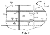
図1に示されているのは、支持体2を含む代表的な微細構造化テープ1の一部の、第1の主面から見た斜視図である。図2に示されているのは、ロール20の形態の微細構造化テープ1の斜視図である。図3及び図4は、それぞれ、支持体2の第1及び第2の主面の平面図を包含する。(それらが描かれているこれら及び全ての他の図において、用語「T」は、テープ1及びその支持体2の短手方向軸を示し、用語「L」はその長手方向軸を示す。)テープ1及びその支持体2は、長手方向軸及び長さと、短手方向軸及び幅と、短手方向小縁部11及び12(即ち、例えば図2に見られる)及び厚さを含む。図1及び図3に示されるように、支持体2は、塗料保持微細構造パターン103を含む第1の主面100を含む。図1及び図4に示されるように、支持体2は、手引き裂き微細構造パターン203を含んでもよい第2の主面200を含む。図1及び図2に示されるように、感圧接着剤300が支持体2の第2の主面200に配置され、例えば感圧接着剤300の第2の主接着面302は、支持体2の第2の主表面215と接触しかつこれと接着付着した状態となる。図2に示されるように、微細構造化テープ1は、剥離ライナーを有さない例えば自己巻き取りロールなどの、長尺長のロールの形態で、都合よく提供されてもよく、該ロールから所与の長さのテープ1を手引き裂きによって取り外すことができる(所望の場合には、ハサミ又は他の切断器具を用いる他の方法を用いてもよい)。次に、感圧接着剤の第1の主接着面301を用いて、所与の長さのテープ1を、マスキングするのが望ましい表面部分に付着させる。その後、マスキングされた表面部分に塗料が侵入することなく、隣接した表面部分を塗装することができる。
Shown in FIG. 1 is a perspective view of a portion of a representative microstructured tape 1 including a
手引き裂き微細構造パターン203とは、複数の脆弱線210を意味し(図1及び4に例示的な方法で示されている)、該脆弱線210は、支持体2の第2の主面200に存在し、支持体2に対して少なくとも略短手方向に配向され、支持体2の幅を略横断して延び、かつ支持体2の長手方向軸に沿って離間配置された長軸を含む。脆弱線210は、所与の長さの支持体2及びテープ1をより大きな長さから(例えば、ロールから)取り外すために、その幅を少なくとも概ね短手方向に横断して手引き裂きされるテープ1の支持体2の能力を増強することができる。(ここで及び本明細書の他の箇所で用いられる)少なくとも概ね短手方向にとは、脆弱線210が必ず支持体2の短手方向軸と厳密に位置合わせされて(例えば、図1〜図3に示される特定の様式で)配向されなければならないことを意味しておらず、むしろ、脆弱線210が支持体2の短手方向軸からプラスマイナス約45度以内の任意の配向である、あらゆる設計を包含する。更なる実施形態において、脆弱線210(即ち、その長軸)は、支持体2の短手方向軸からプラスマイナス約30度、プラスマイナス約20度、又はプラスマイナス約10度以内に配向され得る。具体的な実施形態において、脆弱線210は、支持体2の短手方向軸と厳密に位置合わせされて配向されてもよく、つまり、脆弱線210は支持体2の短手方向軸からプラスマイナス約5度以内で配向される。
The hand
個々の脆弱線210は、それぞれ1つの凹部によって提供される連続した脆弱線であってもよく、又は複数の凹部によって集合的に提供される不連続な脆弱線であってもよい。凹部とは、端部が開口した外側に面する空洞(例えば、窪み、ディボット、切欠き、トレンチ、溝、縦溝、穴等)を含むように、その表面の少なくとも一部が、支持体2の第2の主面200の主表面215(略平坦な平らな表面であり得るが、必ずしもそうではない)よりも下方に(即ち、支持体2の内部に向って内側に向けて)凹んでいる特徴を意味する。本明細書で画定される凹部は、一部の材料(例えば、細孔性材料、発泡体、及び同様のもの)に存在し得るような内部空洞、ボイド、孔、又は同様のものを包含せず、連続気泡発泡体及び同様の表面に存在し得るような孔も包含しない。手引き裂き微細構造パターンとは、脆弱線210を提供する凹部が、約5〜約200ミクロンの範囲の寸法を有する所定の成形構造(例えば、支持体2の第2の主面200に設けられることが望ましい凹部のネガ型を含む成形面に接触させて高分子熱可塑性樹脂を成形することによって得られるようなもの)を、少なくとも2つの直交方向に含むことを更に意味する。これら直交方向のうちの1つは支持体2の平面に垂直であり、したがって、この寸法は凹部の深さを含む。例として、図1及び図4に示されるような細長い溝211からなる凹部によって提供される脆弱線210では、凹部の深さは、溝211の最も深い(最内部)点214が、支持体2の主平面に垂直な軸に沿って、支持体2の第2の主表面215から内側に向けて離間する距離である。多くの場合、溝211の横方向幅(横方向は、溝の幅を横断する方向を意味し、この方向は、支持体2の長手方向軸と概ね位置合わせされる場合が多い)は、第2の直交方向を含み得る。したがって、溝211の深さ及び溝211の横方向幅が、共に、所与の長さの溝211に沿った任意の位置において約5〜約200ミクロンである場合、溝211は、極めて長い長さを有し得るという事実にかかわらず、定義によれば微細構造形体である。いくつかの実施形態では、脆弱線210を提供する凹部は、規則的で予測可能な繰り返しパターンで存在する。
Each
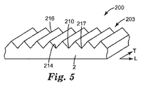
1つ以上の凹部によって提供される脆弱線210が存在することは、支持体2の第2の主面200上に認識可能な平坦な(平らな)表面が必ず存在しなければならないことを意味するものではない。むしろ、いくつかの実施形態では、第2の主面200は、例えば、図5及び図6の代表的な実施形態で示すように、例えば、隆起部216間に点在する溝(谷部)217の形態の脆弱線210を含む手引き裂きパターン203を含む場合がある。そのような場合には、谷部217は凹部を含み、所与の谷部が微細構造化されているか否かを決定する目的で、その深さを、隆起部216の最外部の先端部から、谷部217の最内部(最も深い)の点214までの距離(支持体2の平面に垂直に測定)であると考えることができ、その幅を、隆起部216の先端部から、隣接する隆起部216の先端部までの距離(支持体2の平面と平行に測定)であると考えることができる。したがって、かかる距離が約5ミクロン〜約200ミクロンの範囲内に当てはまる場合、かかる特徴は、本明細書で定義する微細構造化された凹部を含む。更に、隆起部216及び谷部217はそれぞれ、必ずしも鋭い頂点及び床面を有する必要はない。むしろ、頂点及び底のいずれか又は両方は、図6の代表的な実施形態のように丸みを付けられることができ、あるいは、平坦な谷床面及び/又は段頂部等を有することができる。要約すれば、少なくとも概ね短手方向に配向された脆弱線210を提供する起伏のある(例えば、溝付き、波状等)表面を有するあらゆる微細構造パターンを用いることができる。
The presence of the line of
いくつかの実施形態において、連続した脆弱線210を提供する凹部は、支持体2の一方の小縁部11から支持体2のもう一方の小縁部12まで連続的に延在する、連続した細長い溝211を含み得る。種々の実施形態において、溝211の深さは、少なくとも約10ミクロン、少なくとも約15ミクロン、又は少なくとも約20ミクロンであり得る。更なる実施形態において、溝211の深さは、最高約60ミクロン、最高約50ミクロン、又は最高約40ミクロンであり得る。種々の実施形態において、溝211の幅は、少なくとも約20ミクロン、少なくとも約40ミクロン、又は少なくとも約60ミクロンであり得る。更なる実施形態において、溝211の幅は、最高約140ミクロン、最高約120ミクロン、又は最高約100ミクロンであり得る。溝211の幅は、所与の長さの溝211に沿って一定であってもよく、又は該長さに沿って変化してもよい。種々の実施形態において、溝211間の(支持体2に沿った長手方向の)中心間距離は、少なくとも約0.40mm、少なくとも約0.60mm、又は少なくとも約0.80mmであり得る。更なる実施形態において、溝211の間隔は、最高約1.4mm、最高約1.2mm、又は最高約1.0mmであり得る。溝211間の間隔は、所与の長さの支持体2に沿って一定であってもよく、又は様々であってもよい。溝211は、表面215の略平坦部分によって(図1及び図3のように)、若しくは外側に向かって突出した隆起部216によって、又はその両方によって、及び/あるいは任意の他の特徴によって、(支持体2に沿った長手方向に)点在されてもよい。
In some embodiments, the recess that provides the continuous line of
溝211は、所望の場合には、図8及び図9に示される架橋構造212などの任意の特徴を含んでもよい。(図5〜図9の斜視図、並びに図4及び図10〜図13の平面図では、支持体2の第1の主面及びその塗料保持パターン、並びに感圧接着剤300は、説明を明瞭にするために省略されている。)手引き裂きパターン203及び支持体2と一体成形されるそのような架橋構造は、所与の長さの溝211に沿って周期的に離間されていてもよく、溝211の横方向幅(例えば、支持体2の長手方向軸と概ね位置合わせされる方向)の少なくとも一部を横断して延びてもよい。そのような架橋構造は、例えば、脆弱線210として機能する溝211の能力を容認し難いほど低減することなく、支持体2の長手方向の強度を高めることができる。この一般型の特定の実施形態では、架橋構造212は、図8に例示されかつ図9に拡大図として示されるように設計され得る。かかる設計では、架橋構造212は、溝211の幅を実質的に横方向にわたって配向された一番高い隆起部で交わる、2つの主要傾斜面213を含み得る。しかしながら、架橋構造212は、(例えば、略平坦な外側に面する(上部)表面を有する、円形上部表面を有する)など任意の好適な設計を有してもよい。
The
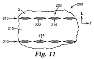
いくつかの実施形態において、脆弱線210は不連続であってもよい、即ち、単一の凹部によって提供されるのではなく、支持体2に対して少なくとも短手横方向に配向され、かつ組み合わさって作用する不連続な脆弱線210の長軸(概ね線状又は厳密に線状の経路であり得るが、必ずしもそうである必要はない)に沿って離間配置された複数の(例えば、2つ以上)凹部によって提供されてもよい。図10に例示された特定の実施例では、間隙(例えば、平らな表面215と関係する)で中断され、したがって支持体2の幅全体を横断して連続的に延在しない、不連続な溝221が提供されてもよい。図11に示されるこのアプローチの変更では、不連続な脆弱線210は、支持体2の短手方向幅にわたって概ね線状に整列配置された複数の細長い楕円形の凹部222によって集合的に提供され、楕円形凹部は、それぞれ支持体2の短手方向幅を概ね横断して配向された長軸を含む。図12に示されるこのアプローチのわずかな変更では、凹部223は、支持体2の短手方向幅にわたって概ね線状に整列配置された菱形の凹部を含み、菱形凹部は、それぞれ支持体2の短手方向幅を概ね横断して配向された長軸を含む。しかしながら、こうしたアプローチは、個々の凹部が、支持体2の短手方向幅を概ね横断して配向された長軸を含むことを必ずしも必要としないことに留意されたい。したがって、図13の代表的な実施形態では、脆弱線210は、略円形の凹部224の列によって集合的に提供されている。(図13及び図7〜図12において、凹部の最も深い内部点は、参照番号214で表されている。)
In some embodiments, the line of
複数の凹部で構成される不連続な脆弱線を含むこれら実施形態のいずれかにおいて、凹部の深さは、少なくとも約10ミクロン、少なくとも約15ミクロン、又は少なくとも約20ミクロンであり得る。更なる実施形態において、凹部の深さは、最高約60ミクロン、最高約50ミクロン、又は最高約40ミクロンであり得る。凹部が長軸を有する場合、凹部の幅は、所与の長さの凹部に沿って一定であり得る(図10のように)、又は、該長さに沿って(図11及び図12のように)変化し得る。種々の実施形態において、凹部の幅(凹部の任意の好適な位置で測定され得、略円形凹部の場合には直径であり得る)は、少なくとも約20ミクロン、少なくとも約40ミクロン、又は少なくとも約60ミクロンであり得る。更なる実施形態では、凹部の幅は、最高約140ミクロン、最高約120ミクロン、又は最高約100ミクロンであり得る。種々の実施形態において、不連続な脆弱線の隣接する凹部の最も近い縁部間の縁部間距離は(例えば、支持体2の短手方向軸に概ね沿って測定する場合)、少なくとも約10ミクロン、少なくとも約20ミクロン、又は少なくとも約30ミクロンであり得る。更なる実施形態において、凹部間の縁部間距離は、最高約200ミクロン、最高約100ミクロン、又は最高約60ミクロンであり得る。 In any of these embodiments including a discontinuous line of weakness comprised of a plurality of recesses, the depth of the recess can be at least about 10 microns, at least about 15 microns, or at least about 20 microns. In further embodiments, the depth of the recess can be up to about 60 microns, up to about 50 microns, or up to about 40 microns. If the recess has a major axis, the width of the recess can be constant along a given length of the recess (as in FIG. 10) or along the length (of FIGS. 11 and 12). Can change). In various embodiments, the width of the recess (which can be measured at any suitable location of the recess and can be the diameter in the case of a generally circular recess) is at least about 20 microns, at least about 40 microns, or at least about 60. Can be micron. In further embodiments, the width of the recess can be up to about 140 microns, up to about 120 microns, or up to about 100 microns. In various embodiments, the edge-to-edge distance between adjacent edges of adjacent recesses of discontinuous lines of weakness (eg, when measured generally along the transverse axis of the support 2) is at least about 10 Micron, at least about 20 microns, or at least about 30 microns. In further embodiments, the edge-to-edge distance between the recesses can be up to about 200 microns, up to about 100 microns, or up to about 60 microns.
1つ以上の凹部によって提供される上記の連続した又は不連続な脆弱線のいずれかにおいて、個々の凹部の深さは様々であってよく、及び/又は異なる凹部は(可変又は一定にかかわらず)異なる深さを含んでもよい。凹部は、異なる幅を有するか、又は同一幅を有し得る。凹部の幅は、例えば、図1の溝211のようにテーパ形状となるように、(例えば、断面で見たときに)支持体2の平面に対して内側−外側に向いた凹部の深さに沿って変化し得る、及び/又は、凹部は、断面で見たときに任意の好適な形状であり得る。即ち、凹部は、その深さに沿って一定幅を含んでもよく、平坦な底部、弓形の底部等、及び/又は、平坦な壁部、傾斜した壁部、弓形の壁部等を含んでもよい。凹部は、断面で見たときに、対称であってもよく、又は対称でなくてもよい。必要なのは、本明細書に記載される能力を手引き裂き支持体2に付与する脆弱線210を、該支持体2の幅を少なくとも概ね短手方向にわたって、個別に又は集合的に提供するように、凹部が適切な形状寸法(例えば、深さ、幅、間隔等)で設計されかつ配置されるということだけである。
In any of the above-described continuous or discontinuous lines of weakness provided by one or more recesses, the depth of the individual recesses can vary and / or different recesses (variable or constant) ) Different depths may be included. The recesses can have different widths or have the same width. The width of the concave portion is, for example, the depth of the concave portion facing inward-outward with respect to the plane of the
脆弱線が連続的又は不連続であるかどうかにかかわらず(連続及び不連続の混合は本明細書の開示に包含される)、個々の脆弱線210間の間隔は、所与の長さの支持体2に沿って一定であってもよく、又は変化してもよい。全ての脆弱線は、(例えば、支持体2の短手方向軸に対して)同一方向に配向される必要はない。更に、本明細書に開示される複数の脆弱線の概念は、特定の脆弱線210を個別に又は集合的に提供する凹部又は複数の凹部は、必ず厳密に一直線に整列配置されなければならないことを意味するものではないことに留意されたい。むしろ、脆弱線の全経路が上記で開示された方法で支持体2を少なくとも概ね短手方向に横断している限り、連続した脆弱線210は、いくらか弓状、波状、正弦波形状、鋸歯状などである連続した溝によって提供されてもよい。同様に、いくらか弓状、波状、正弦波形状、鋸歯状等の経路に沿って配置された複数の凹部も同じように、不連続な脆弱線210を提供することができる。いくつかの実施形態では、言うまでもなく、概ね線状又は厳密に線状の経路が望ましい場合がある。
Regardless of whether the line of weakness is continuous or discontinuous (continuous and discontinuous mixing is included in the disclosure herein), the spacing between the individual line of
このように、本明細書に記載の脆弱線210は、伝播する引き裂きが所望の(例えば、少なくとも概ね短手)方向に、例えば所望の経路に沿って導かれるように、手によって引き裂かれる支持体2の能力を増強又は促進することができる。しかしながら、一部の例では(例えば、不連続な脆弱線がそれぞれ複数の凹部からなる場合、支持体2の長手方向軸に沿って緊密に離間した連続した脆弱線の場合などに起こり得る)、引き裂きの伝播は、厳密な直線経路に沿って真っ直ぐでない場合があることを理解されたい。例えば、引き裂きは、支持体2の短手方向幅を横断する行程の一部で、1つの脆弱線に沿って伝播してもよく、その後第2の隣接する脆弱線(例えば、その凹部)にジャンプした後、第2の脆弱線に沿って短手方向に伝播し続けてもよく、同じように続く。支持体2の幅を横断する所望の(例えば少なくとも概ね短手方向の)経路から引き裂き伝播を容認し難いほど逸脱させない限り、そのような現象も許容可能であり得る。このように、複数の脆弱線の概念は、本明細書では幅広く用いられ、支持体2を手で引き裂くとき、どの特定の脆弱線に追従し得るのかを正確に識別することが必ずしも容易でない、又は可能でない場合の事例も包含する。必要なのは、微細構造化された凹部が、個別に又は集合的に、本明細書に記載の通りに引き裂きを開始させ、かつ、支持体2の幅を少なくとも概ね短手方向にわたって伝播させることができるということだけである。いくつかの実施形態では、言うまでもなく、引き裂きの進行が、概ね又は完全に、1つの脆弱線に沿って生じることが好ましくあり得る。
Thus, the line of
脆弱線210は、伝播している手引き裂きが所望の方向に導かれる能力を高めるのに加えて、手引き裂きが開始される能力を高めることができる。そのため、いくつかの実施形態では、支持体2の小縁部11に存在する脆弱線の少なくとも一部を凹部が構成し、同様に凹部が支持体2の小縁部12に存在するのが有利であり得る。これは、例えば、支持体2の小縁部11及び12まで延びる連続した溝(例えば、図1〜図3の代表的な溝211など)である脆弱線によって提供され得る。又は、不連続な脆弱線の場合には、脆弱線を形成する複数の凹部は、凹部が支持体2の小縁部11に存在するように、かつ凹部が同様に支持体2の小縁部12に存在するように配置され得る。いずれの場合にも、支持体2の第2の主面200の短手方向幅全体にわたって、一方の小縁部11からもう一方の小縁部12まで延在する脆弱線210が提供される。
The line of
塗料保持微細構造パターン103とは、テープ1の支持体2の第1の主面100が、微細構造隔壁102(例えば、図1及び図3に例示的なやり方で示されている)によって画定される(即ち、連続的又は不連続的にかかわらず、境界される)、及びテープ1の第1の主面100に衝突する液体塗料を捕獲及び/又は保持するように構成された、複数の微小容器101を含むことを意味する。そのため、微小容器101の少なくともいくつかは、(例えば所与の長さのテープ1がロールから巻き出されたときに)液体塗料が支持体2に対して略垂直な方向から微小容器101に入るのを防止する別の層又は複数の層で充填される、覆われる、又は該層の下に埋没するのではなく、支持体1の第1の主面100に露出する構成となる。(しかしながら、かかる露出構成は、液体塗料を捕獲及び/又は保持することができる微小容器101を隔壁102が依然として画定するやり方で、隔壁102が1つ以上の絶縁保護コーティング、例えば低接着性バックサイズ及び同様のものでコーティングされるのを妨げない。)種々の実施形態において、微小容器101は、それぞれ少なくとも10,000平方ミクロン、少なくとも約15,000平方ミクロン、又は少なくとも約20,000平方ミクロンの面積を含み得る。更なる実施形態では、微小容器101は、それぞれ最高約700,000平方ミクロン、約400,000平方ミクロン、約100,000平方ミクロン、又は約70,000平方ミクロンの面積を含み得る。微細構造隔壁とは、隔壁102(本明細書で詳細に論じられるように、連続的又は不連続的であってよい)が、それぞれ、所定の成形構造(例えば、支持体2の第1の主面100に設けられることが望ましい形体のネガ型を含む成形面に接触させて高分子熱可塑性樹脂を成形することによって得られる)を含むことを意味する。(隔壁102、並びに脆弱線210を提供する凹部に関して)本明細書で画定する成形構造及び特徴は、後処理(例えば、コーティング、堆積、アブレーション、穿孔、孔抜、ドリル加工、及び同様のものによる)によって達成される特徴と区別されることを理解されたい。微細構造隔壁とはまた、隔壁102が約10ミクロン〜約120ミクロンの範囲の高さを含むことを意味する。これに関して、隔壁高さは、多くの場合、支持体2の主面100の主表面15から、隔壁の外側に向けて最も延出した部分まで、支持体2の平面に垂直な軸に沿って測定した距離であり得る。微細構造隔壁とは、更に、隔壁が、支持体2の平面に対して直角である少なくとも1つの軸に沿って、約5ミクロン〜約200ミクロンの範囲の寸法を有することを意味する。特定の例として、図1に示すような細長いリブ120の形態の隔壁102では、隔壁高さ、即ち、リブ120の最外部部分(先端部)111が、支持体2の主平面に垂直な軸に沿って、支持体2の第1の主表面15から外側に向けて離れて(上方に)離間する距離は、10〜120ミクロンの範囲であり得る。また、リブ120の横方向幅(リブ120の基底部112から先端部111までの範囲の任意の点で測定した場合)は、約5ミクロン〜約200ミクロンの範囲であり得る。その場合、リブ120は、極めて長い長さを有し得るという事実にかかわらず、定義によれば微細構造形体である。いくつかの実施形態では、微細構造隔壁102は、規則的で予測可能な繰り返しパターンで存在する。
The paint-holding
種々の実施形態において、隔壁102の高さ(連続的な細長いリブ、不連続なリブセグメント、ポスト等の形態であるかどうかにかかわらない)は、最高約120ミクロン、最高約100ミクロン、最高約90ミクロン、又は最高約80ミクロンであり得る。更なる実施形態において、隔壁102の高さは、少なくとも約20ミクロン、少なくとも約30ミクロン、又は少なくとも約40ミクロンであり得る。種々の実施形態において、隔壁102の少なくともいくつかは、基底部の対応する寸法の80%未満、約60%未満、又は約40%未満である少なくとも1つの寸法(例えば横方向幅)を有する最上部を含むように、(例えば、図1の代表的な説明図に示すように)テーパ形状であり得る。例えば、リブ120及び/又はリブ133は、図1のようにテーパ形状であってもよく、それにより、最上部111/131の幅は、それぞれ、基底部112/132における幅の約80%未満となる。隔壁102最上部(例えば、細長いリブ120の最上部111及び細長いリブ133の最上部131によって例示される)は、略平坦な領域を含んでもよく、又は滑らかに湾曲していてもよい。隔壁102の少なくともいくつかの任意の部分(例えば、最上部、本体、基底部)は、所望の場合には、小規模な二次的特徴又は同様のものを含んでもよい。
In various embodiments, the height of the septum 102 (regardless of whether it is in the form of continuous elongated ribs, discontinuous rib segments, posts, etc.) is up to about 120 microns, up to about 100 microns, up to about It can be 90 microns, or up to about 80 microns. In further embodiments, the height of the
いくつかの実施形態において、そこから隔壁102が突出する、支持体2の第1の主面100の主表面15は、概ね平らな(平坦な)表面を含み得る。いくつかの実施形態において、1つ以上の微小容器101内の支持体2の主表面15は、任意の二次的特徴を含んでもよい。かかる二次的特徴は、例えば1つ以上の微小容器101内に位置し、容器101内の主表面15から突出する、(例えば、図20に例示的に示されるリブレット118などであるが、ポスト、マウンド、バンプ等を含む場合もある)例えば高さ10ミクロン以下の、例えば1つ以上の凸状特徴を含み得る。凹状の二次的特徴、及び/又は凸状及び凹状の二次的特徴の混合が任意に存在してもよい。いかなる形態であれ、かかる二次的特徴により、微小容器101の底部(例えば、床面)は、増加した表面積、増加した表面粗さ等を含むことができ、このことが、場合によっては、例えば微小容器101内の塗料の定着を増進させることができる。たとえこうした特徴が存在したとしても、平らな主表面15が識別可能である場合には、隔壁102の高さを決定するための基準面として主表面15を使用することができる。しかしながら、いくつかの実施形態では、主表面15は平坦でない場合があり、例えば、容易に認識可能な平らな表面がなく、いくらか粗い表面(規則的又は不規則なパターンであり得る)を含む場合がある。その場合、隔壁102の高さは、そうした不規則な又は多様な主表面の平均平面に対して測定され得る。
In some embodiments, the
微細構造隔壁102は、物理的に互いに交差できない複数の第1の細長い隔壁110と、物理的に互いに交差できない複数の第2の細長い隔壁130とを含み得、第1の隔壁110の少なくともいくつかは、交差点150において第2の隔壁130の少なくともいくつかと交差し、それによって微小容器101を画定する。第1の隔壁110と第2の隔壁130とのこうした交差は、図1及び図14の交差点150と同様に、第1の隔壁110及び第2の隔壁130の実際の物理的な交差点を含み得る。又は、第1の隔壁110と第2の隔壁130とのこうした交差は、図18及び図19の第1の隔壁110及び第2の隔壁130の交差点150と同様に、不連続な隔壁が追従する経路の交差を含み得る(本明細書において以下に詳述する)。いくつかのそのような場合には、第1の隔壁110と第2の隔壁130とのこうした交差は、隔壁の実際の物理的な部分ではなく、空間のある点を含み得る。
The
上記のように、第1の隔壁110は、個々の第1の隔壁110が物理的に互いに交差しないように経路を追従することができ、第2の隔壁130は、個々の第2の隔壁130が物理的に互いに交差しないように経路を追従することができる。いくつかの実施形態において、第1の隔壁110は、厳密に線状であり、かつそれらの長尺長全体に実質的に沿って互いに平行であり得、同様に、第2の隔壁130は、厳密に線状であり、かつそれらの長尺長全体に実質的に沿って互いに平行であり得る。他の実施形態では、第1の隔壁110の少なくともいくつかは、非線形であり得る(例えば、弓状、正弦波形状などである経路を追従し得る)が、局所的に互いに平行であり得(例えば、互いに最接近する点において)、第2の隔壁130も同じである。他の実施形態では、第1の隔壁110の少なくともいくつかは、局所的に平行でなくてもよいが、依然として個々の第1の隔壁110が互いに交差しないように全経路を追従することができ、第2の隔壁130も同じである。いくつかの実施形態では、図1及び図3の代表的な設計のように、第1の隔壁110間の間隔は一定であり得、第2の隔壁130間の間隔は一定であり得、第1及び第2の隔壁の間隔は(即ち、微小容器101が正方形であるように)同じであり得る。他の実施形態では、第1の隔壁110は、第2の隔壁130が互いに離間する距離と異なる距離で互いに離間され得る(即ち、隔壁110及び130によって画定される微小容器101は、正方形ではなく矩形であり得る)。個々の隔壁110間の間隔、及び/又は個々の隔壁130間の間隔は、一定というよりもむしろ様々であってよい。
As described above, the
いくつかの実施形態では、例えば図1及び図3の代表的な実施形態のように、第1の細長い隔壁110は、それらの長尺長(長軸)が長尺長の第2の隔壁130に対して概ね直角であるように提供される(本明細書において以下に詳述するように、隔壁110及び/又は130が、それらの長尺長に沿って連続的又は不連続的であるかどうかにかかわらない)。概ね直角という用語は幅広く用いられ、第1の隔壁110及び第2の隔壁130が互いに対して厳密に直角に位置合わせされる場合に限定することを意図するものではない。むしろ、概ね直角は、(例えば、微小容器101が正方形でなくいくらか菱形であり得るように)70〜110度の任意の角度を包含する。更なる実施形態では、(例えば、正方形の微小容器101を提供するために)第1の隔壁と第2の隔壁との間の角度は、80〜100度、又は88〜92度であり得る。
In some embodiments, for example, as in the exemplary embodiment of FIGS. 1 and 3, the first
支持体2の第1の主面100の第1の隔壁110及び第2の隔壁130は、支持体2の第2の主面200の脆弱線210に関して任意の都合の良い配向で提供され得る。しかしながら、いくつかの実施形態では、第2の隔壁130のいくつか又は全ては、脆弱線210と実質的に位置合わせされ得る、つまり、脆弱線210の長軸からプラスマイナス約20度以内に配向された長軸を有する。更なる実施形態において、第2の隔壁130のいくつか又は全ては、脆弱線210の長軸からプラスマイナス約10度以内に配向された長軸を有し得る。具体的な実施形態では、第2の隔壁130のいくつか又は全ては、脆弱線210と厳密に位置合わせされ得る、つまり、脆弱線210の長軸からプラスマイナス約5度以内に配向された長軸を有する。第2の隔壁130が、例えば脆弱線210と実質的に位置合わせされる、又は厳密に位置合わせされる設計は、脆弱線210(1又は複数)に沿って手で引き裂かれる支持体2の能力を高めることができることを理解されたい。即ち、このような構成は、支持体2を脆弱線210(1又は複数)に沿って手で引き裂くために引き裂かれる(破断される)必要がある第2の隔壁130の数を最小限にすることができる。
The
第1の隔壁110及び第2の隔壁130は、支持体2の長手方向軸及び短手方向軸に関して任意の都合の良い配向で提供され得る。しかしながら、いくつかの実施形態では、第2の隔壁130のいくつか又は全ては、支持体2に対して少なくとも略短手方向に配向され得る、つまり、支持体2の短手方向軸からプラスマイナス約45度以内に配向される長軸を有する。更なる実施形態において、第2の隔壁130のいくつか又は全ては、支持体2の短手方向軸からプラスマイナス約30度、プラスマイナス約20度、又はプラスマイナス約10度以内に配向され得る。具体的な実施形態では、いくつか又は全ての第2の隔壁130は、支持体2の短手方向軸と厳密に位置合わせされ得る、つまり、(例えば、図1及び図3の隔壁130によって例示されるように)支持体2の短手方向軸からプラスマイナス約5度以内に配向される長軸を有する。
The
本明細書の以下の説明から明らかなように、隔壁は必ずしも長軸を有するように連続的である必要がないことを理解されたい。脆弱線に対する隔壁の角度位置合わせ(配向)に関するあらゆる条件は、隔壁が脆弱線210に対して任意の特定の位置に(例えば支持体2の長手方向軸に沿って)設置されることを要求しないことも理解されたい。例えば、脆弱線210は、長手方向に例えば800ミクロンの間隔を置いて配置されてもよく、隔壁130は、長手方向に例えば150ミクロンの間隔を置いて配置されてもよい。そのような場合、いくつかの隔壁130は、支持体2の厚さを介してそれらのちょうど真向かいになる脆弱線を有し得、他の隔壁130は、支持体2の反対側の隣接する脆弱線の間の対向するスペースに配置され得る。即ち、第2の主面の脆弱線と第1の主面の隔壁とは、同じ間隔を有する必要及び/又は互いに位置合わせされる必要はなく、しかしながら、所望の場合にはこれを行うことができる。
As will be apparent from the following description herein, it should be understood that the septum need not be continuous to have a major axis. Any condition regarding the angular alignment (orientation) of the septum with respect to the line of weakness does not require that the septum be placed at any particular position relative to the line of weakness 210 (eg, along the longitudinal axis of the support 2). I want you to understand that. For example, the line of
第2の隔壁130の少なくともいくつかが、支持体2に対し略短手方向に配向される設計は、支持体2の幅を少なくとも概ね短手方向に横断して手で引き裂かれる支持体2の能力を高めることができることを理解されたい。即ち、このような構成は、支持体2をその短手方向幅にわたって手で引き裂くために引き裂かれる(破断される)必要がある第2の隔壁130の数を最小限にすることができる。第2の隔壁130が支持体2に対して厳密に短手方向に配向される設計も同様に、支持体2に対して厳密に横向きの方向に手で引き裂かれる支持体2の能力を高めることができる。
The design in which at least some of the
第1の隔壁110のいくつか又は全ては、支持体2と少なくとも概ね長手方向に位置合わせされる、つまり、支持体2の長手方向軸からプラスマイナス約45度以内に配向される長軸を有する。更なる実施形態では、第1の隔壁110のいくつか又は全ては、支持体2の長手方向軸からプラスマイナス約30度、プラスマイナス約20度、又はプラスマイナス約10度以内に配向され得る。具体的な実施形態では、第1の隔壁110のいくつか又は全ては、支持体2の長手方向軸と厳密に位置合わせされ得る、つまり、(例えば、図1及び図3の隔壁110によって例示されるように)支持体2の長手方向軸からプラスマイナス約5度以内に配向される長軸を有する。
Some or all of the
具体的な実施形態では、第1の隔壁110、及び第2の隔壁130は、それぞれ、(例えば、図1及び図3の第1の細長いリブ120及び第2の細長いリブ133によって例示されるような)連続的な細長いリブを含み得る。したがって、図1及び図3に例示されるタイプの実施形態では、支持体2の第1の主面100は、複数の第1の隔壁110を含むことができ、隔壁110は、それぞれ基底部112及び最上部111、並びに高さ、幅、及び長尺長を有する連続リブ120を含み、この長尺長は、通常、例えば支持体2及びテープ1の長手方向軸と厳密に位置合わせされる。支持体2の第1の主面100は、複数の第2の隔壁130を更に含んでもよく、隔壁130は、それぞれ基底部132及び最上部131、並びに高さ、幅、及び長尺長を有する連続リブ133を含み、この長尺長(長軸)は、通常、例えば支持体2及びテープ1の短手方向軸と厳密に位置合わせされる。図1の具体的な実施形態に示すように、細長いリブ120、及び細長いリブ133は、それぞれ、所与の長さのリブに沿って変化しない均一な高さを含み得る。特定の実施形態では、同様に図1に示されるように、リブ120の高さはリブ133の高さと等しくてもよい。
In a specific embodiment, the
種々の実施形態において、第1の隔壁110は、少なくとも概ね支持体の短手方向軸「T」に沿って手で引き裂かれる支持体2の能力を高めるように設計され得る。例えば、第1の隔壁110が、例えば支持体2の長手方向軸「L」と概ね又は厳密に位置合わせされる場合、これら隔壁の少なくともいくつかは、テープ1の少なくとも概ね短手方向の手による引き裂きの間に引き裂かれる必要があり得る(例えば、短手方向軸「T」と概ね又は厳密に位置合わせされ得、したがって引き裂き方向に対して少なくとも略平行に整列配置され得、したがってテープ1の少なくとも概ね短手方向の手による引き裂きの間に引き裂かれる必要がない第2の隔壁130とは対照的である)。したがって、第1の隔壁110の少なくともいくつかは、第1の隔壁110がもたらす手引き裂きに対する抵抗を最小にするように設計及び/又は配置され得る。
In various embodiments, the
これを行うことができる1つの方法が、図14の代表的な方法に示されている。(図14〜図17及び図20では、説明を明瞭にするために、引き裂きパターン203及び感圧接着剤300は省略されている。)このタイプの設計では、第1の(概ね長手方向に配向された)細長いリブ120の少なくともいくつかの高さは、第2の細長いリブ133の高さよりも短くてもよい。そのような短い方のリブは、支持体をその短手方向幅を少なくとも概ね短手方向に横断して手で引き裂くプロセス中に引き裂きに対する抵抗が小さくなり得る。種々の実施形態において、第1のリブ120のそれぞれは均一な高さを含み得、該均一な高さは、第2のリブ133の高さの約80%未満、又は約60%未満である。更なる実施形態において、第1のリブ120は、それぞれ、第2のリブ133の高さの少なくとも約20%、又は少なくとも約40%である均一な高さを含み得る。例えば、リブ133の高さは約70ミクロンであり得、リブ120の高さは約50ミクロンであり得る。全てのそのようなリブ120の全てのそのようなセグメントは、図14の代表的な実施形態のように、この低い方の高さであり得る(リブ120のセグメントとは、第2のリブ133との交差点150間の所与の長さのリブを意味する)。代替えの構成では、特定のリブ、又はリブの特定のセグメントのみが、かかる低い方の高さであり得る。例えば、2つおき、3つおき、4つおき、又は5つおきのリブ120だけが、かかる低い方の高さであってもよい。いずれの図にも示されていないが、第1のリブ120のいくつか又は全ての厚さは、(第2のリブ133の高さよりも低いことに加えて、又はその代りに)例えば基底部に向って、最上部に向って、及び/又はそれらの間の任意の部分において、第2のリブ133の厚さより狭くてもよく、このこともまた、少なくとも概ね短手方向に手で引き裂かれる支持体2の能力を高めることができる。
One way in which this can be done is shown in the representative method of FIG. (In FIGS. 14-17 and 20, the
少なくとも概ね短手方向に手で引き裂かれる支持体2の能力を高めるように第1の隔壁110を構成することができる別の方法が、図15の代表的な方法に示されている。この一般型の設計では、連続リブセグメント(即ち、第2のリブ133との交差点150同士の間に連続的に延在するセグメント)が、交差点150同士の間にあり、かつ交差点150より遠位である(例えば、交差点150同士間のほぼ真ん中である)位置113におけるリブ120の一部の高さが、第2のリブ133との交差点150に隣接する地点におけるリブセグメントの高さより低くなるように滑らかに変化する輪郭を含む、第1のリブ120が提供され得る。種々の実施形態において、交差点150より遠位の位置113におけるリブ120の高さは、第2のリブ133との交差点150に隣接する位置におけるリブ120の高さの、80%未満、70%未満、又は60%未満であり得る。こうした設計では、リブ133との交差点150におけるリブ120のいくつか又は全ての高さは、リブ133の高さと概ね同じであってもよく(図15の代表的な設計のように)、あるいは、リブ133の高さよりも低くてもよい(例えば、リブ133の高さの80%以下)。少なくとも概ね短手方向に手で引き裂かれる支持体2の能力を必ずしも高めないが、所望の場合には、第2のリブ133も同様に、第1のリブ120との交差点同士の間の位置におけるリブ部分の高さが、第1のリブ120との交差点に隣接する地点における高さより低くなるように滑らかに変化する輪郭を(例えば、本明細書で後に示される代表的な実施例のように)含んでもよい。
Another way in which the
少なくとも概ね短手方向に手で引き裂かれる支持体2の能力を高めるように第1の隔壁110を構成することができる別の方法が、図16の代表的な方法に示されている。このタイプの設計では、リブ120のセグメントの一部に、少なくとも1つの切欠き114が設けられる。切欠き114(V字形、角底などであり得る)は、リブ120の局所的な高さが、リブ133とのリブ120の交差点150に隣接する位置におけるリブ120の高さの約80%未満である最低点を含み得る。種々の実施形態において、この局所的なリブの高さが、リブ133とのリブ120の交差点150に隣接する位置におけるリブ120の高さの約80%未満、約60%未満、約40%未満、又は約20%未満となるように、切欠き114の深さを選択することができる。
Another way in which the
このアプローチの変形では、図17の代表的な設計は、不連続なリブ121の形態の不連続な隔壁110を含む。これに関連して、不連続なリブとは、支持体2の第1の主面100の主表面15が可視となる少なくとも1つの間隙を含むリブを意味する(例えば図1に見られるようなリブ120の形態の隔壁110は、隔壁130とのそれらの交差点150が存在するにもかかわらず、連続的であると画定されることに留意されたい)。図17の代表的な設計では、不連続なリブ121のセグメントにそれぞれこうした間隙115が1つ設けられる。こうしたアプローチの更なる変形が、図18の代表的な方法に平面図で示されており、図中、第1の隔壁110は、外側に向かって突出したポスト116の形態の不連続な隔壁を含む。かかるポストは、図15では略円形として示されているが、任意の好都合な形状であり得る。このタイプの設計では、ポスト116は、適切に設計されかつ離間配置されると、液体塗料の通過を満足のいくように防止又は最低限に抑えるのに少なくとも十分な程度に(例えば、「杭柵」様式で)、集合的に隔壁110として機能し得ることを、当業者は理解するであろう。換言すれば、隔壁102の両方、又は更には一方は、連続的である必要はない。こういう事例として、更に別の可能な設計が図19の代表的な方法に示されており、図中、第1の隔壁110が不連続なだけでなく(ポスト116によって提供される)、第2の隔壁130も不連続である(ポスト117によって提供される)。当業者は、隔壁を集合的に備えるために、一連のポストを必ずしも厳密に線状形式で位置付ける(例えば、図15及び図16のように)必要はないことを理解するであろう。むしろ、ポストが、例えば互いに十分に近接しており、かつ隔壁102を集合的に提供するのに十分な高さ及びサイズ(例えば、幅及び直径)を有するのであれば、ポストは、湾曲、正弦波形状、千鳥、ジグザグなどの形式で提供され得る。こうしたポストは、図18及び図19では円形として示されているが、任意の好都合な形状であり得る。
In a variation of this approach, the exemplary design of FIG. 17 includes a
上記のアプローチの任意の組み合わせを用いることができる。即ち、1つ以上のリブ120の切欠き114又は間隙115を用いる場合、かかるリブ120は、リブ133と同じ高さであってもよく、又はそれより低い高さであってもよい。また、そのような場合には、リブ133は概ね均一な高さを含んでもよく、又は図15に示されるものと類似の弓状の輪郭を有してもよい。全てのリブ133が同一である必要はないことは言うまでもない。更に、当業者は、多くの上記設計間に確固たる境界線が存在し得ないことを理解するであろう。例えば、第1のリブ120のセグメントが、最も低いリブ高さを含む切欠き114によって概ね一定でかつ等しい高さが中断される部分を含む、図16に示されるタイプの設計と、第1のリブ120のセグメントが、最も低いリブ高さを含む点113に対してほぼ滑らかかつ連続的に減少する高さを含む、図15に示されるタイプの設計との間に、確固たる境界線は存在し得ない。同様に、図16のような切欠き114と図17のような間隙115との間に、確固たる境界線は存在し得ない。更に、図17の一般型の不連続なリブ121(間隙又は一連の間隙で中断されたリブセグメントを含む)と、図18及び図19に示される一般型の一連のポスト116との間に、確固たる境界線は存在し得ない。例示的な説明として役立つとして選択された代表的な設計だけでなく、全てのかかる変形及び組み合わせは本明細書の開示に包含されることが理解される。
Any combination of the above approaches can be used. That is, when using
更に、支持体2の横方向への手による引き裂き性を高めると同時に、塗料を捕獲及び保持する塗料保持微細構造パターン103の能力を高めるために、本明細書に提示されているものの中から任意のかかる組み合わせ又は設計を選択することができることに留意されたい。したがって、例えば、第1の隔壁110のいくつか(例えば、3つのうちの2つ、5つのうちの4つなど)は、比較的低い高さのリブを含んでもよく、並びに/又は切欠き、間隙、及び/若しくは切れ目を含んでもよく、特定の残りのリブだけが比較的高い高さを有してもよく、及び/又は切欠き、間隙、切れ目などを含まなくてもよい。これら残りのリブは、介在する低い/切欠きのある/間隙を有する、及び/又は不連続なリブによって互いに離間され得る。低い、及び/あるいは、切欠きのある、若しくは間隙を有する、又は不連続な、第1の隔壁の存在は、支持体2の横方向への手による引き裂き性を高めることができ、一方で、高い、及び/又は切欠き、間隙、又は切れ目を含まない副次的な離間した第1の隔壁は、塗料保持微細構造パターン103が満足のいくように塗料を捕獲及び保持するのを確実にすることができる。
Further, in order to enhance the tearability of the
更に、高さ等が異なる切欠き、間隙、リブ、又はリブセグメントなどの特徴は、主に第1の隔壁110に関して上述されたが、任意のそのような形体及び設計は、所望の場合には、第2の隔壁130で採用されてもよいことに留意すべきである。必要に応じて、特定の目的のために望ましい場合には、例えば支持体2の主表面15から突出する他の特徴(例えば、上記の二次的構造物)を、微小容器101内に設けることができる。
Further, features such as notches, gaps, ribs, or rib segments with different heights etc. have been described above primarily with respect to the
第1の主面100の支持体2及び塗料保持微細構造パターン103、並びに第2の主面200の手引き裂き微細構造パターン203は、一体構造のプラスチック材料で形成された一体構造のプラスチックユニットを構成するものとして本明細書において定義される。これは、塗料保持微細構造パターン103を画定する隔壁102(隔壁102が、図1のように連続した隔壁の形態、図16又は図17のように不連続な隔壁の形態などであるかどうかにかかわらず)が、一体的に支持体2に接続され、支持体2と一緒に成形されることによって形成されたことを意味する。同様に、これは、第2の主面200の手引き裂きパターン203の脆弱線210をもたらす凹状形体(例えば、溝、谷部、孔など)を画定する材料の一部(例えば、表面)が、一体的に支持体2に接続され、支持体2と一緒に成形されることによって形成されたことを意味する。こうした一体構造のプラスチックユニットは、例えば、熱可塑性ポリマーフィルム又は溶融熱可塑性ポリマー押出物を提供し、かつ、支持体2、塗料保持微細構造パターン103を画定する隔壁102、及び手引き裂き微細構造パターン203の脆弱線210をもたらす凹部を、全て同時に一体型ユニットとして形成するように両方の主表面を成形する(例えば、同時に)ことによって、都合よく形成され得る。種々の実施形態において、第2の主面200の第2の主表面215から、隔壁102の最も外側の部分まで(例えば、図1の代表的な実施形態に関して言えば、リブ120の最上部111及びリブ133の最上部131まで)の支持体2の全厚は、少なくとも約25ミクロン、少なくとも約50ミクロン、少なくとも約60ミクロン、又は少なくとも約70ミクロンであり得る。更なる実施形態では、支持体2の全厚は、最高約250ミクロン、最高約140ミクロン、最高約120ミクロン、又は最高約100ミクロンであり得る。いくつかの実施形態では、支持体2を含む材料、第1の主面100の塗料保持微細構造パターン103を画定する隔壁102を含む材料、及びその表面が、第2の主面200の手引き裂きパターン203の脆弱線210をもたらす凹部(例えば、溝、谷部、孔等)を画定する材料は、全て同じ組成物である。
The
支持体2のプラスチック材料は、定義によれば、発泡材料又は多孔質材料でない成形用ポリマー熱可塑性材料である。いくつかの実施形態では、プラスチック材料は非セルロースであり得る、つまり、セルロース系材料(例えば、セルロース、紙、再生セルロース、木質繊維、木粉等、これに関連して、酢酸セルロース及び同様のものはセルロース系材料であると考慮されない)を約5重量%未満含有し得る。特定の実施形態では、プラスチック材料は、溶融加工可能、例えば押出可能であり得る。成形用ポリマー熱可塑性材料は、様々な物質のいずれかから形成され得る、又は様々な物質のいずれかを含むことができる。ホモポリマー、コポリマー、及びポリマーブレンドは有用であり得、様々な添加剤を含有してもよい。好適な熱可塑性ポリマーとしては、例えば、ポリプロピレン若しくはポリエチレンなどのポリオレフィン、ポリスチレン、ポリカーボネート、ポリメチルメタクリレート、エチレンビニルアセテートコポリマー、アクリレートで修飾されたエチレンビニルアセテートポリマー、エチレンアクリル酸コポリマー、ナイロン、ポリ塩化ビニル、及びポリケトン若しくはポリメチルペンタンなどのエンジニアリングポリマーを挙げることができる。ポリマーの混合物も使用することができる。
The plastic material of the
いくつかの実施形態では、プラスチック材料は、本明細書では任意のオレフィンポリマー(例えば、ポリエチレン、ポリプロピレンなど)の任意のホモポリマー、コポリマー、ブレンドと定義されるポリオレフィン系材料であってもよい。いくつかの実施形態では、ポリオレフィン系材料は、ポリエチレンを少なくとも約90重量%、少なくとも約95重量%、又は少なくとも約98重量%含有してもよい(存在し得る無機充填剤の重量は勘定に入れない)。(これに関連して、ポリエチレンとは、少なくとも95%のエチレン単位からなるポリマーを意味する。更なる実施形態では、ポリエチレンはエチレンホモポリマーである。)いくつかの実施形態では、ポリオレフィン系材料は、エチレンホモポリマーから本質的になってもよく、この要件は(無機充填剤の重量は勘定に入れないことに加えて)加工助剤、可塑剤、抗酸化剤、着色剤、顔料、及び同様のもの(これらの少なくともいつくかは、少量の非ポリエチレンポリマーをある程度含有する場合がある)の存在を排除するものではないことに留意されたい。ある実施形態では、ポリオレフィン系材料は、ポリプロピレンを実質的に含有しなくてもよく、並びに非オレフィンポリマーを実質的に含有しなくてもよい。(本明細書で使用する用語「実質的に(含有)しない」は、例えば日常的な洗浄手順に供される大規模な生産設備を使用する場合に生じ得るように、きわめて少量(例えば0.5%以下)の物質がある程度存在するのを排除しないことを、当業者は理解するであろう。) In some embodiments, the plastic material may be a polyolefin-based material defined herein as any homopolymer, copolymer, blend of any olefin polymer (eg, polyethylene, polypropylene, etc.). In some embodiments, the polyolefin-based material may contain at least about 90%, at least about 95%, or at least about 98% by weight of polyethylene (the weight of inorganic filler that may be present is counted). Absent). (In this context, polyethylene means a polymer consisting of at least 95% ethylene units. In a further embodiment, the polyethylene is an ethylene homopolymer.) In some embodiments, the polyolefin-based material is This requirement may consist essentially of ethylene homopolymers (in addition to not counting inorganic filler weight), processing aids, plasticizers, antioxidants, colorants, pigments, and the like Note that this does not preclude the presence of those (at least some of these may contain some small amounts of non-polyethylene polymer). In certain embodiments, the polyolefin-based material may be substantially free of polypropylene and may be substantially free of non-olefin polymers. (As used herein, the term “substantially (free of)” can occur in very small quantities (eg, 0. 0, eg, when using large scale production facilities that are subjected to routine cleaning procedures). One skilled in the art will understand that it does not exclude the presence of some material (less than 5%).)
支持体2で使用するのに適したポリエチレンホモポリマーとしては、例えば、高密度ポリエチレン、中密度ポリエチレン、低密度ポリエチレン、線状低密度ポリエチレン、超低密度ポリエチレンなどを挙げることができる。具体的な実施形態では、ポリエチレンホモポリマーは、低密度ポリエチレン(LDPE、即ち、0.88g/cc〜0.93g/ccの密度を有する)と高密度ポリエチレン(HDPE、即ち、0.94g/cc〜0.97g/ccの密度を有する)との、重量比約90:10 LDPE:HDPE〜約10:90 LDPE:HDPEのブレンドから本質的になってもよい。更なる実施形態では、LDPEとHDPEとの重量比は、約70:30〜約30:70、約60:40〜約40:60、又は約55:45〜約45:55であり得る。具体的な実施形態では、LDPE/HDPEブレンドは、1種以上の無機(例えば、粒子状無機物)充填剤を含んでもよく、該充填剤としては、例えば、炭酸カルシウム、カオリン、タルク、シリカ、二酸化チタン、ガラス繊維、ガラス球などを挙げることができる。こうした充填剤は、支持体2の材料の総重量の約2重量%〜約20重量%の量で存在してもよい。特定の目的のために望ましい場合には、他の添加剤を含んでもよい。
Examples of the polyethylene homopolymer suitable for use in the
図21に示されているのは、支持体2及びテープ1を製造するための代表的な装置及びプロセス400である。溶融熱可塑性ポリマー押出物431を押し出すために押出成形機430を使用することができ、次に、該押出物431の一方の主表面は成形ロール410と接触し、該ロールはその表面に、支持体2の第1の主面100に付与されるべき所望の形体のネガ型を有する。更に、押出品431の反対側の主表面は成形ロール420と接触し、該ロールはその表面に、支持体2の第2の主面200に付与されるべき所望の形体のネガ型を有する。好都合には、接触は、例えばロール410と420との間の狭い間隙(ニップ)の中に溶融押出品431を衝突させることによって、本質的に同時に行うことができる。当業者は、ロール410及び/又は420ではなく、成形ベルト、プラテン、及び同様のものによって提供され得る成形面を、必要に応じて使用することができることを理解するであろう。成形面は金属であってもよく(例えば、金属ロールの形態)、又はより軟質な材料(例えばシリコーンベルト、若しくは金属製の支持ロールの上に配置されたポリマースリーブ又はコーティング)を含み得る。所望の特徴のネガ型をその上に有するかかる成形面は、例えば、当業者によく知られている彫刻、ローレット切り、ダイヤモンド切削、レーザーアブレーション、電気メッキ、又は電気溶着などによって得ることができる。
Shown in FIG. 21 is an exemplary apparatus and process 400 for manufacturing the
成形ロール、例えば金属製の成形ロール、を溶融押出品と組み合わせて使用する場合、ロールを約21℃〜約93℃の温度に維持するのが好都合であり得る。種々の実施形態では、金属製の成形ロールは、約30℃〜約79℃、又は約60℃〜約71℃の温度に維持され得る。押出プロセスを用いる場合、種々の実施形態では、押出可能な組成物(ポリマー樹脂)は、約1〜20、又は約5〜15のメルトフローインデックスを有し得る。所望の場合には、溶融押出品431ではなく、既存の成形用熱可塑性ポリマーフィルムを加熱し、かつ成形面と接触させて、該フィルムの主表面に所望の微細構造パターンを成形することができる。 When a forming roll, such as a metal forming roll, is used in combination with the melt extrudate, it may be advantageous to maintain the roll at a temperature of about 21 ° C to about 93 ° C. In various embodiments, the metal forming roll can be maintained at a temperature of about 30 ° C to about 79 ° C, or about 60 ° C to about 71 ° C. When using an extrusion process, in various embodiments, the extrudable composition (polymer resin) can have a melt flow index of about 1-20, or about 5-15. If desired, an existing thermoplastic polymer film for molding, not the melt-extruded product 431, can be heated and brought into contact with the molding surface to form a desired microstructure pattern on the main surface of the film. .
塗料保持微細構造パターン103を第1の主面100に付与し、かつ手引き裂きパターン203を第2の主面200に付与するために成形面と接触させた溶融押出品432は、その主表面に塗料保持微細構造パターン103及び手引き裂きパターン203を有する支持体2を一体構造のプラスチックユニットとして形成するために、固化され得る。そうした固化を可能にするために、例えば、図21の代表的な方法で示すようにロールのかなりの部分の周囲の経路をたどることによって、成形された押出品を、例えば成形ロールの成形面と接触させた状態で維持することが好都合であり得る。所望の場合には、成形ロールから取り外される際に成形されて固化された支持体2の取り扱いを支援するために、引取ロール425が提供されてもよい。次に、感圧接着剤300が、例えばコーティング機433を使用することによって、支持体2の第2の主面200に配置され得る。感圧接着剤300の堆積は、図21の代表的な構成のように、成形と同じプロセスにおいてインラインで行うことができる。又は、別個のプロセスにおいてオフラインで行うことができる。
The melt-extruded
感圧接着剤(層)300は、例えば、溶媒コーティング法又はホットメルトコーティング法などのコーティング法、例えば、ナイフコーティング、ロールコーティング、リバースロールコーティング、グラビアコーティング、線巻きロッドコーティング、スロットオリフィスコーティング、スロットダイコーティング、押出コーティングなどを含む任意の好適なプロセスによって、第2の主面200上に堆積させることができる。多くの場合、かかるプロセスは、支持体2の第2の主面200上に感圧接着剤前駆体を堆積することと、その後、該前駆体を感圧接着剤300に変換することと(例えば、溶媒の除去、硬化、又は架橋などによる)を含み得る。ただし、接着剤が支持体2の第2の主表面215と密着しかつ接着接合するだけでなく、接着剤が脆弱線210を形成する凹部に侵入して凹部の表面(例えば、壁部、床部等)と密着かつ接着接合するように、接着接合感圧接着剤300を第2の主面200上に堆積させるのが望ましくあり得る。更に、支持体2の第2の主面200の凹部の上にある接着剤300の領域においてでさえも、(例えば、これら領域において窪みを呈するのではなく)接着剤300の外側に面する表面301が略平坦となるような厚さで、感圧接着剤300を凹部の深さに対して提供するのが望ましくあり得る。種々の実施形態において、感圧接着剤300の厚さは、少なくとも約20ミクロン、少なくとも約30ミクロン、又は少なくとも約40ミクロンであり得る。更なる実施形態において、感圧接着剤300の厚さは、最高約100ミクロン、最高約80ミクロン、又は最高約60ミクロンであり得る。
The pressure-sensitive adhesive (layer) 300 is formed by a coating method such as a solvent coating method or a hot melt coating method, for example, knife coating, roll coating, reverse roll coating, gravure coating, wire wound rod coating, slot orifice coating, slot It can be deposited on the second
任意の好適な感圧接着材又は組成物を感圧接着剤300で使用することができる。感圧接着剤は通常、室温で粘着性であり、ただ軽い指圧のみを加えることによって表面に接着されることができ、したがって感圧性でない他のタイプの接着剤と区別することができる。有用な感圧接着剤の一般的な説明は、Encyclopedia of Polymer Science and Engineering,Vol.13,Wiley−Interscience Publishers(New York,1988)に見出すことができる。有用な感圧接着剤の更なる説明は、Encyclopedia of Polymer Science and Technology,Vol.1,Interscience Publishers(New York,1964)に見出すことができる。表面への良好な接着を提供する一方で、残留物(例えば可視残留物)を残すことなく適度な力で取り外し可能であるように接着材を選択するのが好都合であり得る。
Any suitable pressure sensitive adhesive or composition can be used in the pressure
感圧接着剤に適した材料の例としては、例えば、アクリル酸をベースとするポリマー及び/又はメタクリレート材料、天然又は合成ゴム、ブロックコポリマー、シリコーンなどを挙げることができる。好適なポリマー及び/又はそのモノマー単位としては、ポリビニルエーテル、ポリイソプレン、ブチルゴム、ポリイソブチレン、ポリクロロプレン、ブタジエンアクリロニトリポリマー、スチレン−イソプレン、スチレン−ブチレン、及びスチレン−イソプレン−スチレンブロックコポリマー、エチレン−プロピレン−ジエンポリマー、スチレン−ブタジエンポリマー、ポリアルファオレフィン、非晶質ポリオレフィン、ポリシロキサン、エチレン酢酸ビニル、ポリウレタン、ポリビニルピロリドン、並びにこれらの任意の組み合わせを挙げることができる。が、これらに限定されない。好適な(メタ)アクリレート材料の例としては、例えば、メチルメタクリレート、エチルメタクリレート、n−ブチルメタクリレート、メチルアクリレート、エチルアクリレート、n−ブチルアクリレート、イソオクチルアクリレート、イソノニルアクリレート、2−エチル−ヘキシルアクリレート、デシルアクリレート、ドデシルアクリレート、n−ブチルアクリレート、ヘキシルアクリレート、及びそれらの組み合わせなどのアルキルアクリレート又はメタクリレートモノマーのポリマーが挙げられる。市販のブロックコポリマーの例は、商品名「KRATON」でKraton Polymers(Westhollow,TX)から入手可能なものを含む。更に、接着剤は、粘着付与剤、可塑剤、充填剤、抗酸化剤、安定剤、顔料などの添加剤を含有することができる。 Examples of suitable materials for pressure sensitive adhesives include, for example, polymers and / or methacrylate materials based on acrylic acid, natural or synthetic rubbers, block copolymers, silicones and the like. Suitable polymers and / or monomer units thereof include polyvinyl ether, polyisoprene, butyl rubber, polyisobutylene, polychloroprene, butadiene acrylonitrile polymer, styrene-isoprene, styrene-butylene, and styrene-isoprene-styrene block copolymers, ethylene Mention may be made of propylene-diene polymers, styrene-butadiene polymers, polyalphaolefins, amorphous polyolefins, polysiloxanes, ethylene vinyl acetate, polyurethanes, polyvinylpyrrolidone, and any combination thereof. However, it is not limited to these. Examples of suitable (meth) acrylate materials include, for example, methyl methacrylate, ethyl methacrylate, n-butyl methacrylate, methyl acrylate, ethyl acrylate, n-butyl acrylate, isooctyl acrylate, isononyl acrylate, 2-ethyl-hexyl acrylate , Polymers of alkyl acrylate or methacrylate monomers such as decyl acrylate, dodecyl acrylate, n-butyl acrylate, hexyl acrylate, and combinations thereof. Examples of commercially available block copolymers include those available from Kraton Polymers (Westhalllow, TX) under the trade designation “KRATON”. Further, the adhesive can contain additives such as a tackifier, a plasticizer, a filler, an antioxidant, a stabilizer, and a pigment.
図21によって示される一般型のプロセスによって製造されるか、又は任意の他の好適なプロセスによって製造されるかにかかわらず、テープ1は、図2の代表的な方法に示されるロール20の形態で都合よく提供され得る。いくつかの実施形態において、テープ1、及びそのロール20は、いかなる種類の剥離ライナー(例えば、剥離面を有する紙又はプラスチック、フィルム自体によって供給されるか又はフィルム上の低エネルギーコーティングによって供給されるかにかかわらず、かかる剥離ライナーは接着剤の分野で周知である)も含まない。即ち、かかる実施形態のロール20は自己巻き取りロールである、つまり、感圧接着剤300の外向面301が、支持体2の第1の主面100の塗料保持微細構造パターン103を画定する隔壁102の最外面と剥離可能に接触した状態で、それ自体の上に直接巻き取られる。例えば、支持体2が図1に示される一般型である場合、感圧接着剤300は、ロール20の中で、リブ120及び133の少なくとも最上部111及び131と剥離可能に接触することになる。剥離可能な接触とは、ロールの形態を許容できる程度に維持するための機械的完全性を備えたロール20を提供するのに十分な程度に、感圧接着剤300は隔壁102の最外面に接着するが(即ち、それにより、ロールは、自己に巻き付いた状態からあまりにも簡単に容認し難いほど広がらない)、感圧接着剤300と隔壁102の最外面との間の接着力は、許容不可能な力を必要とせずに、かつ隔壁又は接着剤のいずれかを容認し難いほど損なわずに若しくは支持体2の第2の主面200から接着剤を剥離せずに、接着剤300を隔壁表面から剥離及び分離することができるだけ十分に小さいことを意味する。この剥離可能な接触は、例えば本明細書の実施例に記載の手順によって測定した場合に、テープ1をその自己に巻き付いた状態から巻き出すために必要な力として評価され得る。この一般的な方法で測定すると、種々の実施形態において、テープ1は、テープ幅1インチ当たり少なくとも2、3、又は4重量オンス(0.22、0.33、又は0.44N/cmテープ幅)の巻き出し力を含み得る。更なる実施形態では、テープ1は、テープ幅1インチ当たり最大40、30、又は20重量オンス(4.4、3.3、又は2.2N/cmテープ幅)の巻き出し力を含み得る。
Whether manufactured by the general type of process shown by FIG. 21 or by any other suitable process, the tape 1 is in the form of a
感圧接着剤300の接着性及び塗料保持微細構造パターン103の設計は、所望の範囲の巻き出し力を得るような組み合わせで設計され得ることを、当業者は理解するであろう。即ち、感圧接着剤300が接着する大きな表面積を提供することになる、より接近して離間した隔壁及び/又はより広い上面を有する塗料保持微細構造パターン103を、比較的弱い(例えば、粘着性の低い)感圧接着剤組成物と有利に組み合わせることができ、反対に、隔壁が広く離間している及び/又は非常に狭い上面を有する場合には、比較的強く接着する感圧接着剤と有利に組み合わせることができる。これに関連して、感圧接着剤300が接着することができる隔壁102の接着可能な表面積を特徴づけるのも有用であり得る。例えば、図1の代表的な実施形態では、接着可能な表面積は、第1のリブ120の上面111及び第2のリブ133の上面131によって提供され得る。図14の代表的な実施形態では、第1のリブ120の高さは、第2のリブ133よりも十分に短い可能性があるので、接着可能な表面積は、第2のリブ133の上面131によってのみ(及び、例えば、第1のリブ120の上面111によってではない)提供され得る。例えば、(高さが変化する第1のリブ120を有する)図15の代表的な実施形態では、接着可能な表面積は、第2のリブ133の上面131及び第1のリブ120の上面111によって提供され得る。第1のリブ120及び第2のリブ133の両方が、交差点の位置のリブ部分が外側に向けて最も遠くへ突出している弓形形状(例えば、両方のリブが図15の第1のリブ120の形状に似ている)を含む場合には、接着可能な表面積は、主にかかる交差点の位置のリブの上面によって提供され得る。種々の実施形態において、及びどのように達成されるにしても、隔壁102によって提供される接着可能な表面積は、支持体2の第1の主面100の名目表面積(即ち、長さ×幅)の少なくとも約1%、少なくとも約2%、少なくとも約5%、少なくとも約10%、又は少なくとも約15%を構成してもよい。更なる実施形態において、接着可能な表面積は、支持体2の第1の主面100の名目表面積の最高約35%、最高約30%、又は最高約25%を構成してもよい。
Those skilled in the art will appreciate that the adhesion of the pressure
いくつかの実施形態において、支持体2の第1の主面100は、隔壁102に加えて、外側に向けて突出する接着形成体を含んでもよく、この接着形成体は、感圧接着剤300のための接着可能な表面積を提供するように特別に構成されるが、必ずしも液体塗料を捕獲及び/又は保持するプロセスに有意に関与しなくてもよい。かかる接着特徴部は、例えば、隔壁102の最外面を越えて外側へ延び、かつそれらの最外面に接着可能な領域を含む、ポストの形態で提供され得る。
In some embodiments, the first
所望の場合には、支持体2の第1の主面100(例えば、隔壁102の少なくとも最外部の部分及び/又は表面)は、感圧接着剤300がそこに接着する能力を高める又は低減するように処理されてもよい。接着能力を低減することができる処理としては、例えば、隔壁102の最外面に対して低表面エネルギー絶縁保護コーティングを堆積させることが挙げられる。かかる低表面エネルギー絶縁保護コーティングは、いわゆる低接着性バックサイズなどの形態で都合よく入手可能である。所望の場合には、低接着性バックサイズコーティングは、コーティングを主として隔壁102の最外面(即ち、感圧接着剤300が接着可能な表面積)だけに塗布するやり方で(例えばグラビアコーティングにより)塗布されてもよい。あるいは、かかるコーティングはまた、1つ以上の微小容器101内の表面、例えば、微小容器101内の支持体2の主表面15によって提供され得る微小容器101の床面に塗布されてもよい。接着能力を高めることができる処理としては、例えば、コロナ処理、プラズマ処理、火炎処理等、又はプライマー、結合層などの堆積(例えば、コーティング)を挙げることができる。(こうした処理、コーティングなどは、塗料保持微細構造パターン103が液体塗料を保持する能力、及び/又はその上若しくはその中に乾燥した塗料を定着させる能力もまた高めることができることを、当業者は理解するであろう。)同様に、所望の場合には、感圧接着剤300がそこに接着する能力を高めるように、支持体2の第2の主面200を処理することができる。かかる処理は、例えば、コロナ処理、プラズマ処理、火炎処理等、又はプライマー、結合層などの堆積(例えば、コーティング)を含み得る。
If desired, the first major surface 100 (eg, at least the outermost portion and / or surface of the septum 102) of the
テープ1を使用するために、長尺長のテープ(例えばロール20)から所与の長さのテープを取り外すことができる。これは、テープを所望の位置でその短手方向幅にわたって手で引き裂くことによって行われてもよいが、都合がよければ、ハサミ、ナイフ、又は任意の他の好適な切断器具を使用してもよい。手引き裂きは、所望の引き裂き位置を長手方向に一括するテープの部分をそれぞれの手で把持し、テープの幅を少なくとも概ね短手方向に横断する引き裂きを開始及び伝播するために所望の引き裂き位置で剪断力を加えるように、テープの一方の部分を第1の方向に、他方の部分を概ね反対方向に動かすことによって行われてもよい。こうして所与の長さのテープが得られたら、マスキングされるべき表面の所望の部分にこれを適用及び接着することができる。あるいは、まだロール20に取り付けられた状態のテープの末端部を、表面の所望の部分に適用及び接着してもよく、その後、長尺長のテープ(例えば、ロール20自体)の残余部分を、テープの接着していない部分が所与の位置(例えば、テープが表面に接着されている位置に最も近い点)において少なくとも略短手方向に引き裂かれるようにうまく処理(例えば、ひねる又は平行移動させる)してもよい。これら方法はどちらも当業者には周知である。所望の場合には、テープ1をマスキングフィルムと共に使用してもよく、マスキング治具、例えば3M Company(St.Paul,MN)から商品名「3M HAND−MASKER DISPENSER」で入手可能な製品を使用して、テープ1を表面に都合よく適用してもよい(例えば、かかるマスキングフィルムに沿って)。
To use tape 1, a given length of tape can be removed from an elongated tape (eg, roll 20). This may be done by manually tearing the tape across its short width at the desired location, but if convenient, using scissors, a knife, or any other suitable cutting instrument. Good. Manual tearing involves gripping with each hand a portion of the tape that bundles the desired tear locations in the longitudinal direction with each hand and at the desired tear location to initiate and propagate tears that at least cross the width of the tape in the transverse direction. It may be done by moving one part of the tape in a first direction and the other part in a generally opposite direction to apply a shear force. Once a tape of a given length is thus obtained, it can be applied and glued to the desired portion of the surface to be masked. Alternatively, the end of the tape still attached to the
テープ1が表面の所望の部分に適用されたら、続いて表面の隣接部分を所望通りに塗装することができる(塗料という用語は、本明細書では幅広く用いられ、あらゆるコーティング、プライマー、ニス、及び同様のものを包含する)。任意の好適な時点で(例えば、塗料が望ましい程度まで乾燥した後)、テープ1を表面から取り除くことができる。こうした塗料が噴霧器、ブラシ、ローラー等を使用して塗布されるかどうかにかかわらず、任意の好適な液体塗料で塗装する準備として任意の所望の表面をマスキングするために、テープ1を使用することができる(これに関連して、噴霧塗装機はインクジェット装置を明確に除外する)。かかる塗料は、例えばラテックス又は油性のものであり得る。かかる塗料は、例えば、典型的には(重力に対して)水平配向表面上のみに非常に少量(例えば、ピコリットサイズの液滴)で堆積するインクジェットインクなどと区別され得る。そのようなインクジェットインクにおける主な懸念は、典型的には、生成画像の品質である(例えば、堆積した非常に少量の色の異なるインクが、色及び/又は画像の端部を不鮮明にするように互いに移動及び/又は拡散し得る程度を最小限に抑える)。それに対して、本明細書に開示されるテープ1は、例えば高粘度(例えば、>100cps(21℃))のラテックス塗料など、及び例えばテープ1が垂直配向状態の場合などに、塗料の総量を捕獲及び保持できることが判明している。この目的のため、本明細書に開示される塗料保持パターンは、本明細書の実施例から明らかなように、大量の液体塗料を捕獲及び保持する驚くほど高い能力を示すことが見出されている。本明細書の実施例から明らかなように、本明細書に開示される塗料保持パターンは、剥離を阻止する高い能力を有する、パターンの上及び/又は中で乾燥した塗料を提供することも見出されている。具体的には、テープ1を表面から除去する間に時折生じる場合があるテープ1の伸張に際してでさえも、乾燥した塗料は、テープ1からの剥離に対して驚くべき抵抗性があることが見出されている。 Once the tape 1 has been applied to the desired part of the surface, the adjacent part of the surface can then be applied as desired (the term paint is used broadly herein and refers to any coating, primer, varnish, and Including the same). At any suitable time (eg, after the paint has dried to the desired degree), the tape 1 can be removed from the surface. Use tape 1 to mask any desired surface in preparation for painting with any suitable liquid paint, whether or not such paint is applied using a sprayer, brush, roller, etc. (In this connection, the spray coater explicitly excludes the ink jet device). Such paints can be, for example, latex or oily. Such paints can be distinguished, for example, from ink-jet inks that typically deposit in very small amounts (eg, picolit-sized droplets) only on horizontally oriented surfaces (relative to gravity). A major concern in such inkjet inks is typically the quality of the generated image (eg, a very small amount of different colored ink deposited will blur the color and / or the edges of the image. To the extent that they can move and / or diffuse to each other). On the other hand, the tape 1 disclosed in the present specification, for example, a latex paint having a high viscosity (for example,> 100 cps (21 ° C.)), and a case where the tape 1 is in a vertically oriented state, It has been found that it can be captured and retained. For this purpose, the paint retention pattern disclosed herein has been found to exhibit a surprisingly high ability to capture and retain large amounts of liquid paint, as is apparent from the examples herein. Yes. As is clear from the examples herein, it is also seen that the paint retention pattern disclosed herein provides a dry paint on and / or in the pattern with a high ability to prevent delamination. Has been issued. Specifically, the dried paint is found to be surprisingly resistant to peeling from the tape 1, even upon stretching of the tape 1 that may occasionally occur during removal of the tape 1 from the surface. Has been issued.
本明細書に開示されるテープ1は、少なくともいくつかの実施形態において、所望の場合には短手方向に広範囲に湾曲することができるという更なる利点を含む(これは、何らかの装置又はデバイスによって行うことができるかもしれないが、テープのユーザーによって手作業で行われる可能性が高い)。これに関連して、長尺長のテープ1を短手方向に曲げることは、略平坦な平面内にある連続した湾曲形状に形成することを(例えば、図22の代表的な短手方向に湾曲したテープ1のデジタル画像に示されるように)意味する。こうした能力により、従来は一致させるために多くの短い直線長さのテープを組み合わせて使用する必要があった、及び/又は所与の長さのテープを手作業で折り畳む必要があった形状又は縁部(例えば、楕円形又は円形の窓の縁部)と一致するように、テープ1の単一長尺長を短手方向に曲げるのが可能となり得る。短手方向に広範囲に曲げられるテープ1の能力とは、支持体2の少なくともいくつかの部分、例えば支持体2の横向きの小縁部の1つに近い部分(例えば、図22の小縁部12)が、テープ1を短手方向に曲げるために支持体2のこれらの部分に伸張力を加える際に、断裂又は破断せずに少なくとも多少は伸張できなければならないことを意味することを、当業者は理解するであろう。(そのような伸張の証拠は、図22に示される縁部12近くに見ることができる。)それでもなお、支持体2の同じ部分は、テープ1の手引き裂き性を得るために、支持体2に剪断力を加えると少なくとも略短手方向に引き裂かれることができなければならないことが、更に理解されるであろう。こうした能力は互いに相反すると予想され得る。更に、第1の隔壁110の存在は、特にそれらの長軸が支持体2の長手方向軸と概ね(例えば厳密に)位置合わせされて配向される場合に、破断及び伸張の両方に抵抗することになるので、両方の能力を妨げることになることが予想され得る。したがって、塗料保持微細構造パターン103をその上に有する支持体2の、少なくとも概ね短手方向に手で引き裂かれかつ短手方向に曲げられる能力は、予想外の結果を表し、このことは、短手方向に広範囲に湾曲し、かつ縁部13で少なくとも概ね短手方向に(この具体的な事例では、テープの短手方向軸と厳密に位置合わせされている)手で引き裂かれている、図22に示されているテープサンプルによって証明されている。
The tape 1 disclosed herein includes, in at least some embodiments, the additional advantage of being able to bend extensively in the short direction if desired (this may be due to some apparatus or device). May be able to be done, but is likely to be done manually by the tape user). In this connection, bending the long tape 1 in the short direction means forming it into a continuous curved shape in a substantially flat plane (for example, in the typical short direction of FIG. 22). Meaning (as shown in the digital image of the curved tape 1). This capability has traditionally required a combination of many short linear length tapes to match and / or a shape or edge that had to be folded manually for a given length of tape. It may be possible to bend the single long length of the tape 1 in the short direction to coincide with a portion (eg, the edge of an elliptical or circular window). The ability of the tape 1 to be bent extensively in the short direction refers to at least some parts of the
本明細書に開示されるテープ1は、例えば従来の紙ベースのマスキングテープと比較して、切れに対する抵抗があるという更なる利点を含む。更に、本明細書に開示されるテープ1は、例えば従来の紙ベースのマスキングテープと比較して、湿度の望ましくない影響を受けにくいという更に別の利点を含む。更に、本明細書に開示されるテープ1は、粗面又は凹凸面に適合及び接着する改善された能力を含み得、そうした表面上でも良好な塗装ラインをもたらすことができる。 The tape 1 disclosed herein includes the further advantage of being resistant to breakage, for example, compared to conventional paper-based masking tape. Furthermore, the tape 1 disclosed herein includes yet another advantage that it is less susceptible to undesirable effects of humidity compared to, for example, conventional paper-based masking tapes. Furthermore, the tape 1 disclosed herein can include an improved ability to fit and adhere to rough or uneven surfaces and can provide a good paint line on such surfaces.
上述のように、微小容器101を画定する隔壁102を含む塗料保持微細構造パターン103を有するテープは、大量の液体塗料を捕獲及び保持することができ、乾燥した塗料の剥離を阻止する改善された能力を示すことが、予想外に判明した。したがって、本発明のある実施形態では、第2の表面部分を塗装しないようにマスキングした状態で第1の表面部分を塗装する方法であって、該方法が、長手方向軸と短手方向幅及び軸を含む支持体を含み、かつ第1の主面及び相対して面する第2の主面を含む、所与の長さのプラスチックテープを第2の表面部分に接着により取り付けることであって、支持体の第1の主面が塗料保持微細構造パターンを含み、感圧接着剤が支持体の第2の主面に配置され、支持体及び塗料保持微細構造パターンが一体構造のプラスチックユニットを構成することと、液体塗料を少なくとも第1の表面部分に塗布することと、を含む方法が、本明細書において開示される。かかる実施形態では、必ずしも手引き裂きパターンが(例えば、支持体の第2の主面に)存在する必要はない。そのような場合には、支持体の第2の主面の主表面は、例えば略平坦であり得る。
As described above, a tape having a paint holding
本明細書では、主にマスキング用途で使用されるとして、例えば塗装と関連付けて説明されてきたが、当業者は、本明細書に開示されるテープ1は他の用途でも使用することができることを理解するであろう。しかしながら、いずれの用途においても、テープ1がエンドユーザによって使用されるときには、その上に感圧接着剤300を有する支持体2を含むことになり、したがって、支持体2は、接着層との接触から取り外されて、接着剤の実際の最終使用の前に廃棄されるいかなる種類のライナー、剥離ライナー、保護被膜、又は同様のものとも異なり、かつこれらと同等とみなすことはできないことは、当業者には明白であろう。
Although this specification has been described primarily as used in masking applications, for example in connection with painting, those skilled in the art will recognize that the tape 1 disclosed herein can also be used in other applications. You will understand. However, in any application, when the tape 1 is used by an end user, it will include a
例示的な実施形態のリスト
実施形態1.手引き裂き可能なプラスチックテープであって、支持体を含み、該支持体が、長手方向軸、短手方向の幅及び軸、第1の主面、及び相対して面する第2の主面を含み、前記支持体の前記第1の主面が、微小容器を含む塗料保持微細構造パターンを含み、前記微小容器が、複数の第1の微細構造隔壁及び複数の第2の微細構造隔壁によって少なくとも部分的に画定され、該複数の第2の微細構造隔壁の少なくともいくつかが前記第1の微細構造隔壁と交差し、それによって微小容器を画定し、前記支持体の前記第2の主面が、複数の脆弱線を含む手引き裂き微細構造パターンを含み、前記複数の脆弱線の少なくともいくつかが、前記支持体に対して少なくとも略短手方向に配向される長軸を含み、前記支持体の前記第2の主面に感圧接着剤が配置され、前記支持体、前記塗料保持微細構造パターン、及び前記手引き裂き微細構造パターンが全体で一体構造のプラスチックユニットを構成する、手引き裂き可能なプラスチックテープ。
List of Exemplary Embodiments Embodiment 1. A hand tearable plastic tape comprising a support, the support having a longitudinal axis, a transverse width and axis, a first major surface and a second major surface facing oppositely. And the first main surface of the support includes a paint holding microstructure structure pattern including a micro container, and the micro container is at least by a plurality of first microstructure partition walls and a plurality of second microstructure partition walls. Partially defined, at least some of the plurality of second microstructured partitions intersecting the first microstructured partition, thereby defining a microcontainer, wherein the second major surface of the support is Including a hand-tear microstructure pattern including a plurality of lines of weakness, wherein at least some of the plurality of lines of weakness include a major axis that is oriented at least approximately in a lateral direction with respect to the support; Pressure sensitive adhesive is disposed on the second main surface. Is, the support, the coating retaining microstructured pattern, and constitutes the plastic integral unit structure the entire hand tear microstructured pattern, hand tearable plastic tape.
実施形態2.前記脆弱線の少なくともいくつかが、それぞれが前記支持体の前記第2の主面の短手方向幅全体にわたって延在する連続した溝を含む、連続した脆弱線である、実施形態1に記載のテープ。
実施形態3.前記連続した脆弱線の少なくともいくつかが、前記支持体の前記短手方向軸からプラスマイナス5度以内に配向された長軸を含む、実施形態2に記載のテープ。
Embodiment 3. FIG. The tape of
実施形態4.前記連続した溝が長尺長と幅とを含み、前記溝の少なくともいくつかが架橋構造を含み、該架橋構造が、前記支持体と一体成形され、かつ前記溝の前記長尺長に沿って離間配置され、前記架橋構造のそれぞれが、前記支持体の前記長手方向軸と概ね位置合わせされる方向に、前記溝の前記幅の少なくとも一部にわたって延びる、実施形態2又は3に記載のテープ。
Embodiment 4 FIG. The continuous groove includes a long length and a width, and at least some of the grooves include a cross-linking structure, and the cross-linking structure is integrally formed with the support, and along the long length of the groove. 4. The tape of
実施形態5.前記脆弱線の少なくともいくつかが、前記支持体の前記第2の主面の前記短手方向幅全体にわたって延びる連続した細長い谷部をそれぞれが含む連続した脆弱線であり、前記支持体の前記第2の主面の前記短手方向幅にわたって延びる細長い隆起部が、前記支持体の前記長手方向長さに沿って、前記細長い谷部の少なくともいくつかの間に点在する、実施形態1〜4のいずれか一つに記載のテープ。 Embodiment 5. FIG. At least some of the lines of weakness are continuous lines of weakness, each including a continuous elongated valley that extends across the entire width in the transversal direction of the second major surface of the support; Embodiments 1 to 4 wherein elongated ridges extending across the transverse width of two major surfaces are interspersed between at least some of the elongated valleys along the longitudinal length of the support. The tape as described in one.
実施形態6.前記脆弱線の少なくともいくつかが、それぞれが前記支持体の前記第2の主面の第2の主表面内の複数の凹部によって集合的に画定される不連続な脆弱線である、実施形態1に記載のテープ。 Embodiment 6. FIG. Embodiment 1 wherein at least some of the weak lines are discontinuous weak lines, each of which is collectively defined by a plurality of recesses in a second major surface of the second major surface of the support. Tape as described in.
実施形態7.前記不連続な脆弱線の少なくともいくつかが、前記支持体の前記第2の主面の前記短手方向幅全体にわたって延在し、かつ、前記支持体の前記短手方向軸からプラスマイナス5度以内に配向された長軸を含む、実施形態6に記載のテープ。 Embodiment 7. FIG. At least some of the discontinuous lines of weakness extend across the entire width of the second major surface of the support and are plus or minus 5 degrees from the widthwise axis of the support. Embodiment 7. The tape of embodiment 6 comprising a major axis oriented within.
実施形態8.前記塗料保持微細構造パターンが、それぞれが約10,000〜約100,000平方ミクロンの平均面積を含む複数の微小容器を含み、前記第1及び第2の微細構造隔壁の少なくともいくつかが、約30μm〜約80μmの高さを含む、実施形態1〜7のいずれか一つに記載のテープ。 Embodiment 8. FIG. The paint retaining microstructure pattern includes a plurality of microcontainers each having an average area of about 10,000 to about 100,000 square microns, wherein at least some of the first and second microstructured partitions are about Embodiment 8. The tape of any one of embodiments 1 to 7, comprising a height of 30 μm to about 80 μm.
実施形態9.前記第2の微細構造隔壁の少なくともいくつかが、前記脆弱線の少なくともいくつかの長軸からプラスマイナス約20度以内に配向された長軸を含む、実施形態1〜8のいずれか一つに記載のテープ。 Embodiment 9. FIG. Embodiments 1-8 wherein at least some of the second microstructured partitions include major axes oriented within plus or minus about 20 degrees from at least some major axes of the line of weakness. The tape described.
実施形態10.前記第2の微細構造隔壁の少なくともいくつかが、前記支持体に対して少なくとも略短手方向に配向された長軸を含む、実施形態1〜9のいずれか一つに記載のテープ。 Embodiment 10 FIG. Embodiment 10. The tape according to any one of embodiments 1-9, wherein at least some of the second microstructured partitions comprise a long axis oriented at least in a generally transverse direction relative to the support.
実施形態11.前記第2の微細構造隔壁の少なくともいくつかが、前記支持体の前記短手方向軸からプラスマイナス5度以内、及び前記脆弱線の少なくともいくつかの前記長軸からプラスマイナス5度以内に配向された長軸を含む、実施形態1〜10のいずれか一つに記載のテープ。
実施形態12.前記第1の微細構造隔壁の少なくともいくつかが、前記支持体の前記長手方向軸と概ね長手方向に位置合わせされた長軸を含む、実施形態1〜11のいずれか一つに記載のテープ。
実施形態13.前記第1の微細構造隔壁が、それぞれ、前記支持体の前記長手方向軸からプラスマイナス約5度以内に配向された長軸を含み、前記第2の微細構造隔壁が、それぞれ、前記支持体の前記短手方向軸からプラスマイナス5度以内、及び前記脆弱線のそれぞれの前記長軸からプラスマイナス5度以内に配向された長軸を含み、前記脆弱線のそれぞれの前記長軸が、前記支持体の前記短手方向軸からプラスマイナス5度以内に配向される、実施形態1〜12のいずれか一つに記載のテープ。
実施形態14.前記第1の微細構造隔壁の少なくともいくつかが、第1の細長いリブを含み、前記第2の微細構造隔壁の少なくともいくつかが、第2の細長いリブを含む、実施形態1〜13のいずれか一つに記載のテープ。 Embodiment 14 FIG. Embodiments 1-13, wherein at least some of the first microstructured partitions include first elongated ribs and at least some of the second microstructured partitions include second elongated ribs. The tape according to one.
実施形態15.第2の細長いリブが、それぞれ該第2の細長いリブの長尺長に沿って概ね均一である高さを含む、実施形態14に記載のテープ。
実施形態16.前記第1の細長いリブが、前記第2の細長いリブの高さと同じである高さを含み、第1の細長いリブそれぞれの前記高さが、該第1の細長いリブの長尺長に沿って概ね均一である、実施形態14又は15のいずれかに記載のテープ。
Embodiment 16. FIG. The first elongate rib includes a height that is the same as the height of the second elongate rib, and the height of each of the first elongate ribs is along the length of the first elongate rib. 16. A tape according to any of
実施形態17.前記第1の細長いリブのいくつかの少なくともいくつかの部分が、前記第2の細長いリブの前記高さの約40%〜約80%である高さを有する、実施形態14に記載のテープ。 Embodiment 17. FIG. The tape of embodiment 14, wherein at least some portions of some of the first elongate ribs have a height that is about 40% to about 80% of the height of the second elongate rib.
実施形態18.前記第1の細長いリブそれぞれの高さが、該第1の細長いリブの前記長尺長に沿って概ね均一である、実施形態17に記載のテープ。 Embodiment 18. FIG. 18. The tape of embodiment 17, wherein the height of each of the first elongated ribs is generally uniform along the elongated length of the first elongated rib.
実施形態19.前記第1の細長いリブの少なくともいくつかが、該第1の細長いリブと前記第2の細長いリブとの交差点同士の間の位置に、1つ以上の切欠きを含む、実施形態14、15、又は17のいずれか一つに記載のテープ。
Embodiment 19. FIG.
実施形態20.前記第1の微細構造隔壁の少なくともいくつかが、それぞれが一連のリブセグメント又は一連のポストを含む不連続な隔壁である、実施形態1〜13のいずれか一つに記載のテープ。
実施形態21.前記プラスチック材料が、存在するいかなる無機充填剤も差し引いて、低密度ポリエチレンと高密度ポリエチレンとの重量比約60:40〜約40:60のブレンドから本質的になるポリエチレンホモポリマーを少なくとも約95重量%含有する、実施形態1〜20のいずれか一つに記載のテープ。 Embodiment 21. FIG. At least about 95 weight of polyethylene homopolymer, wherein the plastic material consists essentially of a blend of low density polyethylene to high density polyethylene in a weight ratio of about 60:40 to about 40:60, minus any inorganic filler present. The tape according to any one of Embodiments 1 to 20, wherein the content is%.
実施形態22.前記感圧接着剤が、(メタ)アクリレート接着剤、天然ゴム系接着剤、合成ゴム接着剤、シリコーン接着剤、及びブロックコポリマー接着剤からなる群から選択される、実施形態1〜21のいずれか一つに記載のテープ。 Embodiment 22. FIG. Any of embodiments 1-21, wherein said pressure sensitive adhesive is selected from the group consisting of (meth) acrylate adhesives, natural rubber adhesives, synthetic rubber adhesives, silicone adhesives, and block copolymer adhesives. The tape according to one.
実施形態23.前記テープが、当該テープの前記第1の主面の前記第1の微細構造隔壁及び/又は第2の微細構造隔壁の少なくとも一部と前記感圧接着剤の主表面とが剥離可能に接触する、自己巻き取りロールの形態の長尺長を含む、実施形態1〜22のいずれか一つに記載のテープ。 Embodiment 23. FIG. In the tape, at least a part of the first microstructured partition and / or the second microstructured partition on the first main surface of the tape and the main surface of the pressure-sensitive adhesive are detachably contacted. The tape according to any one of embodiments 1-22, comprising a long length in the form of a self-winding roll.
実施形態24.当該手引き裂き可能なプラスチックテープが、弓形形状へと短手方向に湾曲可能である、実施形態1〜23のいずれか一つに記載のテープ。 Embodiment 24. FIG. Embodiment 24. The tape according to any one of embodiments 1 to 23, wherein the hand tearable plastic tape can be bent in a short direction into an arcuate shape.
実施形態25.第2の表面部分を塗装しないようにマスキングした状態で第1の表面部分を塗装する方法であって、所与の長さの手引き裂き可能なプラスチックテープを前記第2の表面部分に接着により取り付ける工程であって、前記プラスチックテープが、長手方向軸と短手方向の幅及び軸、第1の主面、及び相対して面する第2の主面を含む支持体を含み、該支持体の前記第1の主面が塗料保持微細構造パターンを含み、前記支持体の前記第2の主面が手引き裂き微細構造パターンを含み、前記支持体の第2の主面に感圧接着剤が配置され、前記支持体、前記塗料保持微細構造パターン、及び前記手引き裂き微細構造パターンが全体で一体構造のプラスチックユニットを構成する、取り付ける工程と、少なくとも前記第1の表面部分に液体塗料を塗布する工程と、を含む方法。 Embodiment 25. FIG. A method of painting a first surface portion in a masked state so that the second surface portion is not painted, wherein a hand-tearable plastic tape of a given length is attached to the second surface portion by adhesion A plastic tape comprising a support comprising a longitudinal axis and a transverse width and axis, a first major surface, and a second major surface facing oppositely; The first main surface includes a paint-holding fine structure pattern, the second main surface of the support includes a hand tearing fine structure pattern, and a pressure sensitive adhesive is disposed on the second main surface of the support. And a step of attaching the support, the paint-holding fine structure pattern, and the hand tearing fine structure pattern as a whole to form a unitary plastic unit, and applying a liquid paint to at least the first surface portion. The method comprising the step, the.
実施形態26.前記液体塗料が、ブラシ、ローラー、又は噴霧器によって塗布される、実施形態25に記載の方法。 Embodiment 26. FIG. 26. The method of embodiment 25, wherein the liquid paint is applied by a brush, roller, or sprayer.
実施形態27.前記塗料が、21℃において少なくとも100cpsの粘度を有するラテックス塗料である、実施形態25又は26に記載の方法。 Embodiment 27. FIG. 27. The method of embodiment 25 or 26, wherein the paint is a latex paint having a viscosity of at least 100 cps at 21 ° C.
実施形態28.前記所与の長さの手引き裂き可能なプラスチックテープが、前記第2の表面部分に接着により取り付けられる前に、手引き裂き可能なプラスチックテープのロールから手で引き裂かれる、実施形態25〜27のいずれか一つに記載の方法。 Embodiment 28. FIG. Embodiment 25 The method as described in one.
実施形態29.前記液体塗料を少なくとも前記第1の表面部分に塗布した後、前記所与の長さのテープを前記第2の表面部分から除去する更なる工程を含む、実施形態25〜28のいずれか一つに記載の方法。 Embodiment 29. FIG. Embodiment 25. Any of Embodiments 25-28, comprising the further step of removing the given length of tape from the second surface portion after applying the liquid paint to at least the first surface portion. The method described in 1.
実施形態30.前記方法が、前記第2の表面部分の弓形形状と一致させるために、前記所与の長さの手引き裂き可能なプラスチックテープの少なくとも一部を短手方向に曲げる工程と、短手方向に湾曲した前記テープを、弓形形状の前記第2の表面部分に接着により取り付ける工程とを含む、実施形態25〜29のいずれか一つに記載の方法。 Embodiment 30. FIG. Bending the at least a portion of the given length of the hand tearable plastic tape in a short direction to match the arcuate shape of the second surface portion; 30. The method of any one of embodiments 25-29, comprising attaching the tape to the arcuately shaped second surface portion by adhesive bonding.
実施形態31.塗料保持微細構造パターンを有する第1の主面と、手引き裂き微細構造パターンを有する第2の相対して面する主面とを有する支持体を含む手引き裂き可能なプラスチックテープの製造方法であって、溶融ポリマー押出品の第1の主表面を、前記塗料保持微細構造パターンのネガ型を含む第1の成形面と接触させ、かつ、前記溶融ポリマー押出品の第2の主表面を、前記手引き裂き微細構造パターンのネガ型を含む第2の成形面と接触させる工程であって、前記溶融ポリマー押出品の前記第1の主表面が第1の成形型に接して成形され、前記溶融ポリマー押出品の前記第2の主表面が第2の成形型に接して成形され、それによって前記支持体の前記第1の主面に塗料保持微細構造パターンを有し、かつ前記支持体の前記第2の主面に手引き裂き微細構造パターンを有する前記支持体を形成する、接触させる工程と、前記支持体の前記第2の主面に感圧接着剤を配置する工程と、を含む方法。 Embodiment 31. FIG. A method for producing a hand tearable plastic tape comprising a support having a first major surface having a paint retaining microstructure pattern and a second oppositely facing major surface having a hand tear microstructure pattern. A first main surface of the molten polymer extrudate is brought into contact with a first molding surface including a negative mold of the paint holding microstructure structure, and a second main surface of the molten polymer extrudate is A step of bringing into contact with a second molding surface including a negative mold having a tearing microstructure pattern, wherein the first main surface of the molten polymer extrudate is molded in contact with the first mold, and the molten polymer pressing The second main surface of the exhibit is molded against a second mold, thereby having a paint retaining microstructure pattern on the first main surface of the support, and the second of the support. Hand tear on the main surface of Wherein said forming a support, comprising the steps of contacting, placing a pressure sensitive adhesive on the second major surface of said support, a having a microstructured pattern.
実施形態32.前記第1及び第2の成形面が、第1及び第2の成形型ロールの概ね相対して面する表面部分、又は第1及び第2の成形型ベルトの概ね相対して面する表面部分を含み、当該方法が、前記溶融ポリマー押出品の前記第2の主表面が前記第2の成形面に接して成形されるのと同時に、前記溶融ポリマー押出品の前記第1の主表面が前記第1の成形面に接して成形されて、長尺長の支持体を形成するように、前記溶融ポリマー押出品を前記概ね相対して面する第1の成形面と第2の成形面との間に送り込む工程と、前記感圧接着剤を長尺長の前記支持体の前記第2の主面に配置して、長尺長の手引き裂き可能なプラスチックテープを形成する工程と、を含む、実施形態31に記載の方法。 Embodiment 32. FIG. The first and second molding surfaces are generally opposed surface portions of the first and second mold rolls, or generally opposed surface portions of the first and second mold belts. And the method is such that the first major surface of the molten polymer extrudate is the first major surface simultaneously with the second major surface of the molten polymer extrudate being shaped in contact with the second molding surface. Between the first molding surface and the second molding surface facing the generally opposite facing of the melted polymer extrudate so as to form an elongated support that is molded in contact with the first molding surface. And a step of disposing the pressure-sensitive adhesive on the second main surface of the elongate support to form an elongate hand tearable plastic tape. The method according to form 31.
実施形態33.前記手引き裂き微細構造パターンが複数の脆弱線を含み、該複数の脆弱線が、前記支持体の前記第2の主面の前記第2の主表面内の1つ以上の凹部によってもたらされ、かつそれぞれが深さを含み、前記感圧接着剤を前記長尺長の支持体の前記第2の主面に配置することが、前記長尺長の支持体の前記第2の主表面に感圧接着剤前駆体をコーティングした後、前記感圧接着剤が前記凹部を充填し、かつその表面に接着接合されるように、前記感圧接着剤前駆体を前記感圧接着剤に変換することによって行われる、実施形態31又は32に記載の方法。 Embodiment 33. FIG. The hand tear microstructure structure includes a plurality of lines of weakness, the plurality of lines of weakness being provided by one or more recesses in the second major surface of the second major surface of the support; And each including a depth, and placing the pressure sensitive adhesive on the second main surface of the elongate support is sensitive to the second main surface of the elongate support. After coating the pressure-sensitive adhesive precursor, converting the pressure-sensitive adhesive precursor to the pressure-sensitive adhesive so that the pressure-sensitive adhesive fills the recess and is adhesively bonded to the surface thereof. Embodiment 33. The method of embodiment 31 or 32 performed by
実施形態34.前記感圧接着剤の主表面が前記テープの前記第1の主面の前記塗料保持微細構造パターンを画定する微細構造隔壁の少なくとも一部と剥離可能に接触する自己巻きロールを形成するために、手引き裂き可能な前記長尺長のテープを自己巻き取りすることを更に含む、実施形態31〜33のいずれか一つに記載の方法。 Embodiment 34. FIG. In order to form a self-winding roll in which the major surface of the pressure sensitive adhesive releasably contacts at least a portion of the microstructure partition that defines the paint holding microstructure pattern of the first major surface of the tape. The method of any one of embodiments 31-33, further comprising self-winding the elongate tape that is manually tearable.
実施形態35.前記溶融ポリマー押出品が、存在するいかなる無機充填剤も差し引いて、低密度ポリエチレンと高密度ポリエチレンとの重量比約60:40〜約40:60のブレンドから本質的になる、実施形態31〜34のいずれか一つに記載の方法。 Embodiment 35. FIG. Embodiments 31-34, wherein the molten polymer extrudate consists essentially of a blend of low density polyethylene to high density polyethylene in a weight ratio of about 60:40 to about 40:60 minus any inorganic filler present. The method as described in any one of.
実施形態36.塗装されないように第2の表面部分をマスキングした状態で第1の表面部分を塗装する方法であって、前記方法が、長手方向軸及び短手方向幅及び軸を含む支持体を含み、かつ第1の主面及び相対して面する第2の主面を含む、所与の長さのプラスチックテープを第2の表面部分に接着により取り付けることであって、前記支持体の前記第1の主面が塗料保持微細構造パターンを含み、感圧接着剤が前記支持体の前記第2の主面に配置され、前記支持体及び前記塗料保持微細構造パターンが一体構造のプラスチックユニットを構成することと、液体塗料を少なくとも前記第1の表面部分に塗布することと、を含む。 Embodiment 36. FIG. A method of coating a first surface portion with the second surface portion masked so that it is not painted, the method comprising a support comprising a longitudinal axis and a transverse width and axis, and Attaching a given length of plastic tape to a second surface portion, including a first major surface and a second major surface facing oppositely, the first major surface of the support. The surface includes a paint holding microstructure pattern, a pressure sensitive adhesive is disposed on the second main surface of the support, and the support and the paint holding microstructure pattern constitute a unitary plastic unit; Applying a liquid paint to at least the first surface portion.
実施形態37.前記方法が、実施形態8、10、12、及び14〜24のいずれか一つを含むテープを使用する、実施形態36に記載の方法。
Embodiment 37. FIG. 37. The method of embodiment 36, wherein the method uses a tape comprising any one of
実施形態38.前記方法が、実施形態1〜24のいずれか一つを含むテープを使用する、実施形態25〜30のいずれか一つに記載の方法。 Embodiment 38. FIG. The method of any one of embodiments 25-30, wherein the method uses a tape comprising any one of embodiments 1-24.
テープ支持体の製造−代表的な実施例
装置
テープ支持体の押出し及び成形を、図21に示される一般型のプロセスラインを使用して行った。直径約12インチ(30.5cm)及び総面幅約16インチ(40.6cm)の第1の金属製成形ロールを入手した。この総面幅のうち、中央の12インチ(30.48cm)を、それぞれが、わずかに異なる塗料保持パターンのネガ型を有する3つの4インチ(10.2cm)幅の横区域に分割した。3つの区域のそれぞれは、(ダイヤモンド切削により)第1及び第2の平行な主溝の組を含み、第1の組の主溝のそれぞれは成形ロールの周りに円周方向に延び、第2の組の主溝のそれぞれは、(その区域内の)成形ロール面をわたって短手方向に延びた。第1及び第2の主溝はテーパ形状であり、約15度の夾角を含む平坦な側壁を備え、溝底(即ち、溝の最深地点)は平坦で約10ミクロンの幅を有し、かつ成形ロールの平らな表面の下約80ミクロンの深さに位置した。3つの区域間の唯一の違いは、中央区域では、主溝のそれぞれの組は約153μmの中心間距離を有し、横方向外方区域の一方では、主溝は約191μmの間隔を有し、他方の横方向外方区域は約127μmの間隔を有したことだけであった。
Production of Tape Support—Representative Example Equipment The extrusion and molding of the tape support was performed using a general process line as shown in FIG. A first metal forming roll having a diameter of about 12 inches (30.5 cm) and a total face width of about 16 inches (40.6 cm) was obtained. Of this total face width, the central 12 inch (30.48 cm) was divided into three 4 inch (10.2 cm) wide transverse sections, each with a slightly different negative pattern of paint holding pattern. Each of the three sections includes a set of first and second parallel main grooves (by diamond cutting), each of the first set of main grooves extending circumferentially around the forming roll and second Each of the main grooves in the set extended in the short direction across the forming roll surface (in that area). The first and second main grooves are tapered, have flat sidewalls including a depression angle of about 15 degrees, the groove bottom (ie, the deepest point of the groove) is flat and has a width of about 10 microns, and Located about 80 microns deep below the flat surface of the forming roll. The only difference between the three zones is that in the central zone, each set of main grooves has a center-to-center distance of about 153 μm, while in the lateral outer zone, the main grooves have a spacing of about 191 μm. The other laterally outer area only had a spacing of about 127 μm.
3つの区域は全て一組の二次溝を更に含み、これら溝は、全て互いに平行であり、かつ全て成形ロールの周りに円周方向に配向された(即ち、第1の主溝の組と整列配置された)。二次溝は全て、成形ロールの平らな表面の下約10ミクロンの深さを有し、かつ、約30度の夾角を含む平坦な側壁と、幅約10ミクロンの平坦な溝底とを有するテーパ形状であった。二次溝の中心間距離は約25ミクロンであった。 All three zones further include a set of secondary grooves, all of which are parallel to each other and are all circumferentially oriented around the forming roll (ie, the first main groove set and Aligned). All secondary grooves have a flat sidewall having a depth of about 10 microns below the flat surface of the forming roll and including a depression angle of about 30 degrees, and a flat groove bottom having a width of about 10 microns. It was a tapered shape. The distance between the centers of the secondary grooves was about 25 microns.
直径約12インチ(30.5cm)及び総面幅約16インチ(40.6cm)の第2の金属製成形ロールを入手した。ロール面のパターン付き部分には、それぞれロールの面にわたって短手方向に延び、かつロールの周囲を囲むように離間した複数の平行して突出する隆起部が(ダイヤモンド切削によって)設けられた。隆起部は、それぞれ、第2の成形ロールの平らな表面から33ミクロン上方にある頂点を含んだ。隆起部は、それぞれ、互いに対して約130度の角度をなす平坦な側壁を備えた。隆起部のそれぞれの基底部(成形ロールの平らな表面に隣接する)は、幅約140ミクロンであった。隆起部は、約940ミクロンの中心間距離で第2の成形ロールの周りに周囲方向に離間配置された。隆起部は、それぞれ、隆起部の幅の一部にわたって短手方向に延びる(即ち、第2の成形ロール面の周りに円周方向に配向される)、交差して線状の谷部を形成する2つの平面をそれぞれが備える一連の二次切欠きを含んだ。線状の谷部のそれぞれは、隆起部頂点より約24ミクロン下方(したがって、成形ロールの平らな表面から約9ミクロン上方)に位置した。二次切欠きそれぞれの2つの平面は、互いに対して約124度の角度をなした。二次切欠きは、隆起部それぞれに沿って約340ミクロンの間隔で離間配置された。 A second metal forming roll having a diameter of about 12 inches (30.5 cm) and a total face width of about 16 inches (40.6 cm) was obtained. The patterned portion of the roll surface was provided (by diamond cutting) with a plurality of parallel protruding ridges extending in the lateral direction over the surface of the roll and spaced apart to surround the roll. Each of the ridges contained a vertex that was 33 microns above the flat surface of the second forming roll. Each of the ridges had flat sidewalls that were at an angle of about 130 degrees relative to each other. Each base of the ridge (adjacent to the flat surface of the forming roll) was about 140 microns wide. The ridges were spaced circumferentially around the second forming roll with a center-to-center distance of about 940 microns. Each of the ridges extends in a short direction over a part of the width of the ridge (ie, is oriented circumferentially around the second forming roll surface) and intersects to form a linear valley It included a series of secondary notches, each with two planes. Each of the linear valleys was located about 24 microns below the ridge apex (and thus about 9 microns above the flat surface of the forming roll). The two planes of each secondary notch made an angle of about 124 degrees with respect to each other. Secondary notches were spaced about 340 microns apart along each ridge.
材料及びプロセス
密度0.918g/cm3及びメルトフローインデックス12の低密度ポリエチレン(LDPE)(Dow Plasticsより商品名「4012」で入手)を約48.5重量%と、密度0.965g/cm3、メルトフローインデックス8.3の高密度ポリエチレン(HDPE)(Dow Plasticsより商品名「8007」で入手)を約48.5重量%と、(濃縮物のポリマー担体樹脂は記録されていなかったが、ポリエチレン材料と思われる)青色染料濃縮物を約3重量%含む、押出可能組成物を得た。材料は乾燥ペレットの形態で入手し、乾式混合し、直径2.5インチ(6.4cm)の一軸スクリュー押出機に送り、公称ギャップ20ミル(508μm)(形成されるウェブのクロスウェブキャリパーを最適化するために必要に応じて調整することができる)を含む幅12インチ(30.5cm)のキャストフィルムダイを通して押出した。ダイの温度を約218℃に設定し、溶融押出品を約1525psi(10500kPa)の融解圧力で押出した。押出品を押出し、分速約15.2メートルのライン速度で処理した。
Materials and Processes Low density polyethylene (LDPE) with a density of 0.918 g / cm3 and a melt flow index of 12 (obtained under the trade name “4012” from Dow Plastics) at about 48.5% by weight, a density of 0.965 g / cm3, melt High-density polyethylene (HDPE) with a flow index of 8.3 (obtained under the trade name “8007” from Dow Plastics) was about 48.5% by weight (the polymer carrier resin of the concentrate was not recorded, but the polyethylene material An extrudable composition was obtained containing about 3% by weight of a blue dye concentrate. The material is obtained in the form of dry pellets, dry mixed and sent to a 2.5 inch (6.4 cm) diameter single screw extruder, with a nominal gap of 20 mils (508 μm) (optimized web cross-web caliper formed) And extruded through a 12 inch (30.5 cm) wide cast film die. The die temperature was set at about 218 ° C. and the melt extrudate was extruded at a melt pressure of about 1525 psi (10500 kPa). The extrudate was extruded and processed at a line speed of about 15.2 meters per minute.
約100pli(ポンド/リニアインチ幅)(175N/リニアcm幅)程度の圧力下で第1及び第2の成形ロールを寄せてニップを形成した。両方の成形ロール(2重螺旋シェル構造を含んだ)は内部循環水によって温度制御され、約66℃の公称温度に維持された。溶融押出品が、溶融押出品の流れの第1の主面で、第1の成形ロール中の第1及び第2の主溝の組の組に流れ込むように、溶融押出品を成形ロールの間のニップに通過させ、先に述べた一般型の第1及び第2の細長いリブの組を形成した(固化後)。第1の組のリブは、こうして形成された支持体の長手方向軸に沿って配向され、第2の組のリブは、この支持体の短手方向軸に沿って配向された。溶融押出品の流れの第2の主面で、溶融押出品は第2の成形ロールの突出した隆起部の上及び周囲を流れ、こうして形成された支持体の幅にわたって短手方向に配向された溝を形成した(固化後)。本明細書の図8及び図9に示す一般型の隆起した架橋構造を形成するために、溶融押出品は隆起部の中の二次切欠きに流れ込んだ。 The nip was formed by bringing the first and second forming rolls together under a pressure of about 100 pli (pound / linear inch width) (175 N / linear cm width). Both forming rolls (including the double helical shell structure) were temperature controlled by internal circulating water and maintained at a nominal temperature of about 66 ° C. The molten extrudate flows between the forming rolls such that the molten extrudate flows into the set of first and second main grooves in the first forming roll at the first main surface of the flow of the molten extrudate. The first and second elongated rib sets of the general type described above were formed (after solidification). The first set of ribs was oriented along the longitudinal axis of the support thus formed, and the second set of ribs was oriented along the short axis of the support. On the second major surface of the flow of the melt extrudate, the melt extrudate flows over and around the protruding ridges of the second forming roll and is oriented in the transverse direction over the width of the support thus formed. Grooves were formed (after solidification). The melt extrudate flowed into the secondary notches in the ridges to form the general type of raised cross-linked structure shown in FIGS. 8 and 9 herein.
押出品は巻き角度約135度まで第2の成形ロールとの接触を維持し、その時点で固化した支持体は図21の一般的な方法でこの成形ロールから取り外され、引取ロールの上を通過した。次に、固化した支持体はロール状に巻かれることができた。こうして形成された支持体の全厚さは、典型的には120ミクロン程度であった(支持体の第1の主面の塗料保持パターンの隔壁(リブ)の高さを含む)。先に挙げた特定の処理条件下では、溶融押出品は、(深さ80μmの)主溝の溝の底部まで完全に侵入しなかった。むしろ、侵入は、支持体の第1の主面が、図15のリブ120によって示される一般型の比較的滑らかに変化する輪郭を呈する、支持体の長手方向軸に沿って配向された隔壁(細長いリブ)の第1の組を含むようなものであった。第1のリブと第2のリブとの交差点同士の間の位置における第1のリブの高さは、約31ミクロン程度と推定された。同様に、支持体は、支持体の幅にわたって短手方向に配向された、同様に比較的滑らかに変化する輪郭を呈する隔壁(細長いリブ)の第2の組を含み、第2のリブと第1のリブとの交差点同士の間の位置における第2のリブの高さは、約45ミクロン程度と推定された。第1のリブと第2のリブの交差点におけるリブの高さは、約58ミクロン程度と推定された。
The extrudate maintains contact with the second forming roll until a winding angle of about 135 degrees, at which point the solidified support is removed from this forming roll in the general manner of FIG. 21 and passes over the take-up roll. did. Next, the solidified support could be wound into a roll. The total thickness of the support thus formed was typically about 120 microns (including the height of the partition walls (ribs) of the paint holding pattern on the first main surface of the support). Under the specific processing conditions listed above, the melt extrudate did not penetrate completely to the bottom of the main groove (80 μm deep). Rather, the intrusion is a septum oriented along the longitudinal axis of the support, in which the first major surface of the support exhibits a relatively smooth changing profile of the general type shown by
支持体の第2の主面は、支持体の幅にわたってほぼ短手方向に配向された(支持体の第2の主面の平らな表面において)深さ約33ミクロン、幅約140ミクロンの連続脆弱線(溝)を含んだ。 The second major surface of the support is oriented approximately laterally across the width of the support (on the flat surface of the second major surface of the support) and is continuous at a depth of about 33 microns and a width of about 140 microns. It included a weak line (groove).
変形例
上記の代表的な実施例の多くの変形を、様々なプロセスライン条件、樹脂組成物などに関して実施した。いくつかの実験では、LDPEとHDPEとの比を、約10:90〜90:10の範囲で変化させた。いくつかの実験では、リエチレンとプロピレンとのブレンドを用いた。いくつかの実験では、様々な充填剤(例えば、タルク、シリカ、炭酸カルシウム等)を組成物に加えた。いくつかの実験では、成形ロールの温度を約38℃〜93℃の範囲で変化させた。
Variations Many variations of the above exemplary embodiments were implemented for various process line conditions, resin compositions, and the like. In some experiments, the ratio of LDPE to HDPE was varied in the range of about 10:90 to 90:10. In some experiments, a blend of reethylene and propylene was used. In some experiments, various fillers (eg, talc, silica, calcium carbonate, etc.) were added to the composition. In some experiments, the temperature of the forming roll was varied in the range of about 38 ° C to 93 ° C.
テープの製造
前述の一般的な方法で様々な支持体を製造し、次に、その第2の主面(手引き裂きパターンを含む)上に感圧接着剤を提供した。接着剤を堆積する前に、支持体を、それぞれが上記の3つの塗料保持パターンのうちの1つを含む別個のロールに切り離すのが大抵は便利であった。典型的には、接着剤を支持体上に提供する前に、支持体の第2の主表面を(ロールを切り離す前であるか後であるかを問わず)コロナ処理した(当業者に周知の従来法によって)。様々な実験において、感圧接着剤は、感圧接着剤前駆体を支持体の表面に堆積(例えばコーティング)し、この前駆体を感圧接着剤に変換することによって、支持体の第2の主面に提供された。様々な実験において、これは、接着剤前駆体溶液をコーティングし、コーティング溶媒を乾燥させることによって、接着剤前駆体水性混合物をコーティングし、水を乾燥させることによって、ホットメルト接着剤前駆体を堆積し、この前駆体を固化することによって、及び同様の方法によって達成された。接着剤は、溝の上に位置する領域内の感圧接着剤の最外表面に対応する窪みがほとんど存在しないように、支持体の第2の主表面上の溝を接着剤が充填するやり方で及びかかる厚さで堆積するのが多くの場合好都合であることが見出された。
Tape Manufacture Various supports were manufactured by the general method described above and then a pressure sensitive adhesive was provided on its second major surface (including hand tear pattern). Prior to depositing the adhesive, it was often convenient to separate the support into separate rolls each containing one of the three paint holding patterns described above. Typically, the second major surface of the support is corona treated (whether before or after the roll has been cut off) (provided by those skilled in the art) before the adhesive is provided on the support. By conventional methods). In various experiments, the pressure sensitive adhesive is deposited on (eg, coated with) a pressure sensitive adhesive precursor on the surface of the support, and the precursor is converted to a pressure sensitive adhesive by converting the precursor to a second pressure sensitive adhesive. Provided on the main surface. In various experiments, this deposits a hot melt adhesive precursor by coating the adhesive precursor solution, coating the adhesive precursor aqueous mixture by drying the coating solvent, and drying the water. And achieved by solidifying this precursor and by similar methods. The manner in which the adhesive fills the groove on the second major surface of the support so that there is little depression corresponding to the outermost surface of the pressure sensitive adhesive in the region located above the groove. It has been found that it is often convenient to deposit at such a thickness.
これら実験では、アクリレート系接着剤、ゴム系接着剤、シリコーン系接着剤,ブロックコポリマー系接着剤等などの、多様なタイプの感圧接着剤を含むテープを製造した。典型的には、接着剤をその上に有するテープは自己巻き取りされ(剥離ライナーを有さない)、その後、本明細書において後に示すデータによって証明されるように、テープは満足のいくように巻き出されることができた。 In these experiments, tapes containing various types of pressure sensitive adhesives such as acrylate adhesives, rubber adhesives, silicone adhesives, block copolymer adhesives, and the like were manufactured. Typically, a tape having an adhesive thereon is self-wound (no release liner), and then the tape is satisfactory as evidenced by the data presented later in this specification. Could be unwound.
液体塗料保持能力試験
(実施例)
代表的な実施例に記載された一般型の塗料保持パターンを有し、かつ本明細書に記載される組成物で形成されるプラスチック支持体のサンプルを作製し、塗料保持パターンの細長いリブは約153ミクロンの間隔を含んだ。
Liquid paint retention ability test (Example)
A sample of a plastic support having the general type of paint holding pattern described in the exemplary embodiment and formed of the composition described herein is made, and the elongated ribs of the paint holding pattern are about A spacing of 153 microns was included.
比較例
微細構造化されておらず、かつ平滑面を含む従来の高密度ポリエチレンプラスチックフィルムを含む第1の比較サンプルを得た。3M Companyから商品名「SCOTCH−BLUE 2090」で入手可能な従来の紙製マスキングテープで使用されるタイプの青色のマスキング紙を含む第2の比較サンプルを得た。
Comparative Example A first comparative sample comprising a conventional high density polyethylene plastic film that was not microstructured and contained a smooth surface was obtained. A second comparative sample was obtained containing a blue masking paper of the type used in the conventional paper masking tape available under the trade designation “SCOTCH-BLUE 2090” from 3M Company.
手順及び結果
約5グラムのSherwin−Williams A−100屋外用アクリル塗料を、周囲温度でフィルムサンプルのそれぞれの表面に注いだ。フィルムサンプルごとに新しいブラシを使用して、塗布された塗料を、サンプル表面にわたって又はブラシから塗料が広がらなくなるまでブラシの片面のみを使用して塗った。塗料保持パターンを含むプラスチックフィルム上の5グラムの塗料は、70平方インチ(452cm2)を覆うように広がった。微細構造化されていないプラスチックフィルム上の5グラムの塗料は、144平方インチ(929cm2)を覆うように広がった。青色マスキング紙上の5グラムの塗料は、104平方インチ(671cm2)を覆うように広がった。サンプルのそれぞれに関するフィルム面積当たりのおよその液体塗料保持力を、表1に示すように、1平方フィート当たり(0.093平方メートル当たり)のグラムで計算することができた。
Procedure and Results Approximately 5 grams of Sherwin-Williams A-100 outdoor acrylic paint was poured onto each surface of the film sample at ambient temperature. A new brush was used for each film sample, and the applied paint was applied using only one side of the brush over the sample surface or until the paint did not spread from the brush. Five grams of paint on the plastic film containing the paint holding pattern spread over 70 square inches (452 cm 2 ). Five grams of paint on unstructured plastic film spread to cover 144 square inches (929 cm 2 ). Five grams of paint on blue masking paper spread to cover 104 square inches (671 cm 2 ). The approximate liquid paint retention per film area for each of the samples could be calculated in grams per square foot (per 0.093 square meter) as shown in Table 1.

試験は半定量的でしかないが、塗料保持微細構造パターンを有するプラスチックフィルムは、非構造化HDPEプラスチックフィルム又は青色マスキング紙のどちらよりも、面積当たりより多くの液体塗料を受ける及び保持することができたことを示した。 Although the test is only semi-quantitative, a plastic film with a paint-retaining microstructure pattern can receive and retain more liquid paint per area than either an unstructured HDPE plastic film or blue masking paper. I showed that I was able to do it.
乾燥塗料の定着能力試験
(実施例)
以下に記載の違いを有する代表的な実施例と同様のタイプのポリマー支持体を得た。支持体の第1の主面は、直交配向された隔壁の第1及び第2の組を含む塗料保持パターンを含み、隔壁のそれぞれの組は平行に連続的な細長いリブを含む。それぞれの組のリブ間の間隔は約250ミクロンであった。それぞれの組のリブの高さは記録されなかった。直交配向されたリブの第1及び第2の組はそれぞれ、ポリマー支持体の長手方向軸に対して約45度の角度で配向された(一組が支持体の長手方向軸と位置合わせされ、一組が長手方向軸に直交した代表的な実施例と対照をなす)。塗料保持パターンは、代表的な実施例に記載された一般型の二次リブレットを更に含み、その高さは約10ミクロンであり、第1及び第2の組のリブに対して約45度で配向された。支持体は、支持体の第2の主面に手引き裂きパターンも感圧接着剤も含まなかった。支持体はポリプロピレンからなった。
Fixing ability test of dry paint (Example)
A polymer support of the same type as in the representative examples having the differences described below was obtained. The first major surface of the support includes a paint holding pattern that includes first and second sets of orthogonally oriented partitions, each set of partitions including elongated parallel ribs. The spacing between each set of ribs was about 250 microns. The height of each set of ribs was not recorded. The first and second sets of orthogonally oriented ribs were each oriented at an angle of about 45 degrees relative to the longitudinal axis of the polymer support (one set aligned with the longitudinal axis of the support, Contrast with an exemplary embodiment where one set is orthogonal to the longitudinal axis). The paint holding pattern further includes a general type of secondary riblet as described in the exemplary embodiment, the height is about 10 microns, and about 45 degrees relative to the first and second sets of ribs. Oriented. The support contained no hand tear pattern or pressure sensitive adhesive on the second major surface of the support. The support was made of polypropylene.
様々な液体塗料を支持体サンプルの第1の主面にブラシで塗布し、少なくとも約48時間にわたって約32℃で乾燥させた。乾燥後、表面が柔らかい4.5kgのローラーを使用して、3M #2090マスキングテープを塗料サンプルの上部に接着させた。マスキングテープサンプルを少なくとも約24時間にわたって放置した。次に、マスキングテープサンプルをフィルムサンプルから手作業で剥離し、フィルム上に定着したままの乾燥塗料の量(マスキングテープによって剥がされた乾燥塗料の量ではない)を目視で検査した。第1の主面(塗料保持パターンを有する)に次の様々な表面処理が施されたフィルムサンプルを試験した:処理なし、コロナ処理、コロナ処理+低接着性バックサイズ(よく使用される低接着性バックサイズを代表すると考えられる)のコーティング、及びコロナ処理+プライマーコーティング(よく使用されるプライマーコーティングを代表すると考えられる)。いくつかのラテックス塗料、ラテックプライマー、オイルベースのプライマー、半透明のラテックスステイン、無色のラテックスステイン、及びオイルベースのステインを含む様々な塗料を評価した。概ね全てのケースで、塗料保持パターンへの乾燥塗料の優れた定着が観察され、ごくわずかな塗料が#2090マスキングテープに移着した、又は#2090マスキングテープをはがす際に塗料保持パターンから除去された。 Various liquid paints were brushed onto the first major surface of the substrate sample and dried at about 32 ° C. for at least about 48 hours. After drying, 3M # 2090 masking tape was adhered to the top of the paint sample using a 4.5 kg roller with a soft surface. The masking tape sample was left for at least about 24 hours. The masking tape sample was then manually peeled from the film sample and visually inspected for the amount of dry paint that remained fixed on the film (not the amount of dry paint removed by the masking tape). Film samples with various primary surface treatments on the first major surface (with paint retention pattern) were tested: no treatment, corona treatment, corona treatment + low adhesion backsize (commonly used low adhesion) Coating), and corona treatment + primer coating (which is considered to be representative of commonly used primer coatings). Various paints were evaluated, including several latex paints, latex primer, oil-based primer, translucent latex stain, colorless latex stain, and oil-based stain. In almost all cases, excellent fixation of the dry paint to the paint holding pattern was observed and very little paint was transferred to the # 2090 masking tape or removed from the paint holding pattern when the # 2090 masking tape was removed. It was.
テープのロールの巻き出し力試験
(実施例)
乾燥塗料の定着能力試験に記載されたものと同様のタイプ及び組成物のポリマーフィルムを得た。フィルムは、その第1の主面に、代表的な実施例で記載されたものと概ね同様のタイプの細長いリブを備える隔壁の第1及び第2の組を含む塗料保持パターンを有した。1つは細長いリブのそれぞれの組が約250ミクロン離間し、1つは細長いリブのそれぞれの組が約125ミクロン離間している、2つのタイプのフィルムを得た。隔壁高さは記録されなかった。隔壁の第1及び第2の組は、互いに対して直角であり、それぞれ、ポリマーフィルムの長軸に対して約45度で配向された(即ち、これら隔壁は、上記乾燥塗料の定着能力試験で使用したフィルムと同様のパターンを有した)。塗料保持パターンは、代表的な実施例に記載された一般型の二次リブレットを更に含み、その高さは約10ミクロンであり、第1及び第2の組のリブに対して約45度で配向された。フィルムは、フィルムの第2の主面に手引き裂きパターンを含まなかった。
Tape unwinding force test (Example)
A polymer film of the same type and composition as described in the fixing ability test of dry paint was obtained. The film had a paint holding pattern on its first major surface comprising first and second sets of septa with elongated ribs of a type generally similar to that described in the representative examples. Two types of films were obtained, one with each set of elongated ribs spaced about 250 microns apart and one with each set of elongated ribs spaced about 125 microns apart. The septum height was not recorded. The first and second sets of partition walls are perpendicular to each other and each oriented at about 45 degrees with respect to the long axis of the polymer film (ie, these partition walls were tested in the fixability test of the dry paint). It had the same pattern as the film used). The paint holding pattern further includes a general type of secondary riblet as described in the exemplary embodiment, the height is about 10 microns, and about 45 degrees relative to the first and second sets of ribs. Oriented. The film did not contain a hand tear pattern on the second major surface of the film.
感圧接着剤前駆体コーティング混合物を2種類得た。第1の混合物は、アクリレートポリマーとKratonブロックコポリマー(Kraton Performance Polymers,Inc.(Houston,TX)より入手可能)との第1のブレンドを含む水性接着剤コーティング混合物であった。第2の混合物は、アクリレートポリマーとKratonブロックコポリマーとの第2のブレンドを含むホットメルトコーティング混合物であった。これらは共に、当業者に一般に知られた一般型の接着剤前駆体組成物を含み、第2の接着剤前駆体は第1の混合物よりも強力な感圧接着剤(即ち、より高度な粘着性及び接着性を有する)を提供するために選択された。コーティング混合物を、従来のコーティング法を用いてポリマーフィルムの第2の主面(即ち、手引き裂きパターンのない平面)上にコーティングし、感圧接着剤をその上に提供した。次に、感圧接着剤をその上に有するポリマーフィルムを、感圧接着剤の外表面が塗料保持パターンの隔壁の最外面と接触するように、自己巻き取りロール(剥離ライナーを有さない)に巻き取った。 Two types of pressure sensitive adhesive precursor coating mixtures were obtained. The first mixture was an aqueous adhesive coating mixture comprising a first blend of an acrylate polymer and a Kraton block copolymer (available from Kraton Performance Polymers, Inc., Houston, TX). The second mixture was a hot melt coating mixture comprising a second blend of acrylate polymer and Kraton block copolymer. Both of these comprise a general type of adhesive precursor composition generally known to those skilled in the art, where the second adhesive precursor is a stronger pressure sensitive adhesive (ie, a higher degree of tack) than the first mixture. Selected to provide the same and adhesive properties). The coating mixture was coated onto the second major surface of the polymer film (i.e., a plane without a hand tear pattern) using a conventional coating method and a pressure sensitive adhesive was provided thereon. Next, a self-winding roll (with no release liner) is placed on the polymer film having the pressure-sensitive adhesive thereon so that the outer surface of the pressure-sensitive adhesive contacts the outermost surface of the partition wall of the paint holding pattern. Rolled up.
ロールからテープの層を巻き出すための力は、テープールを滑り/剥離試験装置(Model 3M90,IMASS Inc.,Hingham,Mass.)の巻き固定具(spool fixture)に取り付け、テープロールからテープを巻き出すのに必要な力を、テープロールに対して180(度)の角度にて90インチ/分(229cm/分)の剥離速度で測定することによって評価された。約5秒の実行時間にわたる平均力を測定し、テープの1インチ(幅)当たりの重量オンス(テープの1cm幅当たり0.11N)で報告した。巻き出し力は、コーティング直後(例えば、数時間以内)、及び約21℃、約50%相対湿度にて約12週間老化させた後に再度、測定した。結果を表2に示す。 The force for unwinding the tape layer from the roll is obtained by attaching the tapel to a spool fixture of a sliding / peeling test apparatus (Model 3M90, IMASS Inc., Hingham, Mass.) And winding the tape from the tape roll. The force required to dispense was evaluated by measuring at a peel rate of 90 inches / min (229 cm / min) at an angle of 180 (degrees) to the tape roll. Average force over a run time of about 5 seconds was measured and reported in weight ounces per inch (width) of tape (0.11 N per cm width of tape). The unwind force was measured again immediately after coating (eg, within a few hours) and after aging for about 12 weeks at about 21 ° C. and about 50% relative humidity. The results are shown in Table 2.
テープを手で引き裂く及び短手方向に曲げる能力の試験
(実施例)
一般型のテープ(例えば代表的な実施例で例示されたもの)の多数のサンプルを作製し、該テープは、第1の主面に塗料保持パターンを含み、かつ第2の主面に手引き裂きパターン及び感圧接着剤を含んだ。かかるテープの多くは、例えば図22の手で引き裂いた縁部13から明らかなように、テープの幅にわたって満足のいくように手引き裂きされることができた。これに加えて、かかるテープの多くは、例えば図22に示されるテープの手作業で短手方向に湾曲した部分から明らかなように、満足のいくように短手方向に曲げることができた。
Test of ability to tear tape by hand and bend in short direction (Example)
A number of samples of a general type tape (e.g., illustrated in the representative examples) are made, the tape includes a paint holding pattern on the first major surface and a hand tear on the second major surface. Pattern and pressure sensitive adhesive were included. Many such tapes could be hand-teared satisfactorily across the width of the tape, as is evident, for example, from the hand-teared
上記の試験及び試験結果は予測ではなく例示のみを意図したものであり、試験方法が変われば異なる結果が生じ得ることが考えられる。実施例の項における定量的な値はすべて、用いられる手順にともなう一般的に既知の許容誤差を考慮した近似的な値であるものと理解される。上記の詳細な説明及び実施例はあくまで理解を助けるために示したものである。これらによって不要な限定をするものと理解されるべきではない。 The above tests and test results are intended only for illustration and not prediction, and it is possible that different results may occur if the test method changes. All quantitative values in the examples section are understood to be approximate values taking into account generally known tolerances associated with the procedure used. The above detailed description and examples are given for the purpose of understanding only. These should not be construed as making unnecessary limitations.
当業者には、本明細書に開示される具体的な例示的構造、特徴、細部、構成などは多くの実施形態において改変かつ/又は組み合わせることが可能である点は明らかであろう。そのような改変及び組み合わせは全て、本発明の範囲内にあるものとして発明者らによって想到される。したがって、本発明の範囲は、本明細書に記載される特定の例示的構造に限定されるべきではないが、むしろ少なくとも請求項の言語によって説明される構造、及びそれらの構造に相当する構造にまで拡大する。参照により本明細書に援用したいずれかの文書内での仕様と開示との間の不一致及び矛盾が存在するという点に関して、本仕様書は制御されるであろう。 It will be apparent to those skilled in the art that the specific exemplary structures, features, details, configurations, etc. disclosed herein can be modified and / or combined in many embodiments. All such modifications and combinations are contemplated by the inventors as being within the scope of the present invention. Accordingly, the scope of the present invention should not be limited to the specific exemplary structures described herein, but rather at least the structures described by the language of the claims and structures corresponding to those structures. Expand to. This specification will be controlled in that there are discrepancies and inconsistencies between the specification and disclosure within any document incorporated herein by reference.
Claims (35)
支持体を含み、該支持体が、長手方向軸、短手方向の幅及び軸、第1の主面、及び相対して面する第2の主面を含み、
前記支持体の前記第1の主面が、微小容器を含む塗料保持微細構造パターンを含み、前記微小容器が、複数の第1の微細構造隔壁及び複数の第2の微細構造隔壁によって少なくとも部分的に画定され、該複数の第2の微細構造隔壁の少なくともいくつかが前記第1の微細構造隔壁と交差し、それによって微小容器を画定し、
前記支持体の前記第2の主面が、複数の脆弱線を含む手引き裂き微細構造パターンを含み、前記複数の脆弱線の少なくともいくつかが、前記支持体に対して少なくとも略短手方向に配向される長軸を含み、
前記支持体の前記第2の主面に感圧接着剤が配置され、
前記支持体、前記塗料保持微細構造パターン、及び前記手引き裂き微細構造パターンが全体で一体構造のプラスチックユニットを構成する、手引き裂き可能なプラスチックテープ。 Hand tearable plastic tape,
Including a support, the support including a longitudinal axis, a lateral width and axis, a first major surface, and a second major surface facing away from each other;
The first main surface of the support includes a paint holding microstructure pattern including a microcontainer, and the microcontainer is at least partially defined by a plurality of first microstructure partition walls and a plurality of second microstructure partition walls. Wherein at least some of the plurality of second microstructured partitions intersect the first microstructured partition, thereby defining a microcontainer,
The second main surface of the support includes a hand-tear microstructure structure including a plurality of weak lines, and at least some of the plurality of weak lines are oriented in at least a substantially short direction with respect to the support. Including the major axis
A pressure sensitive adhesive is disposed on the second main surface of the support;
A hand tearable plastic tape in which the support, the paint-holding fine structure pattern, and the hand tear fine structure pattern constitute an integral plastic unit as a whole.
所与の長さの手引き裂き可能なプラスチックテープを前記第2の表面部分に接着により取り付ける工程であって、前記プラスチックテープが、長手方向軸と短手方向の幅及び軸、第1の主面、及び相対して面する第2の主面を含む支持体を含み、該支持体の前記第1の主面が塗料保持微細構造パターンを含み、前記支持体の前記第2の主面が手引き裂き微細構造パターンを含み、前記支持体の第2の主面に感圧接着剤が配置され、前記支持体、前記塗料保持微細構造パターン、及び前記手引き裂き微細構造パターンが全体で一体構造のプラスチックユニットを構成する、取り付ける工程と、
少なくとも前記第1の表面部分に液体塗料を塗布する工程と、
を含む方法。 A method of painting the first surface portion in a state of being masked so as not to paint the second surface portion,
Attaching a hand-tearable plastic tape of a given length to the second surface portion by bonding, wherein the plastic tape comprises a longitudinal axis and a transverse width and axis, a first major surface; And a support including a second main surface facing oppositely, wherein the first main surface of the support includes a paint retaining microstructure pattern, and the second main surface of the support is a hand. A plastic including a tearing microstructure pattern, wherein a pressure sensitive adhesive is disposed on the second main surface of the support, and the support, the paint-holding microstructure pattern, and the hand tearing microstructure pattern are integrated as a whole Constructing and attaching the unit; and
Applying a liquid paint to at least the first surface portion;
Including methods.
溶融ポリマー押出品の第1の主表面を、前記塗料保持微細構造パターンのネガ型を含む第1の成形面と接触させ、かつ、前記溶融ポリマー押出品の第2の主表面を、前記手引き裂き微細構造パターンのネガ型を含む第2の成形面と接触させる工程であって、前記溶融ポリマー押出品の前記第1の主表面が第1の成形型に接して成形され、前記溶融ポリマー押出品の前記第2の主表面が第2の成形型に接して成形され、それによって前記支持体の前記第1の主面に塗料保持微細構造パターンを有し、かつ前記支持体の前記第2の主面に手引き裂き微細構造パターンを有する前記支持体を形成する、接触させる工程と、
前記支持体の前記第2の主面に感圧接着剤を配置する工程と、
を含む方法。 A method for producing a hand tearable plastic tape comprising a support having a first major surface having a paint retaining microstructure pattern and a second oppositely facing major surface having a hand tear microstructure pattern. ,
A first main surface of the molten polymer extrudate is brought into contact with a first molding surface including a negative mold of the paint holding microstructure structure, and a second main surface of the molten polymer extrudate is hand-teared. A step of bringing into contact with a second molding surface including a negative mold having a microstructure pattern, wherein the first main surface of the molten polymer extrudate is molded in contact with the first mold, and the molten polymer extrudate The second main surface of the support is molded in contact with a second mold, thereby having a paint holding microstructure pattern on the first main surface of the support, and the second of the support. Forming the support having a hand-teared microstructure pattern on the main surface, and contacting
Placing a pressure sensitive adhesive on the second main surface of the support;
Including methods.
Applications Claiming Priority (3)
| Application Number | Priority Date | Filing Date | Title |
|---|---|---|---|
| US13/042,536 | 2011-03-08 | ||
| US13/042,536 US8530021B2 (en) | 2011-03-08 | 2011-03-08 | Microstructured tape |
| PCT/US2012/025811 WO2012121869A2 (en) | 2011-03-08 | 2012-02-20 | Microstructured tape |
Publications (2)
| Publication Number | Publication Date |
|---|---|
| JP2014514374A true JP2014514374A (en) | 2014-06-19 |
| JP2014514374A5 JP2014514374A5 (en) | 2015-04-02 |
Family
ID=46795824
Family Applications (1)
| Application Number | Title | Priority Date | Filing Date |
|---|---|---|---|
| JP2013557737A Pending JP2014514374A (en) | 2011-03-08 | 2012-02-20 | Microstructured tape |
Country Status (11)
| Country | Link |
|---|---|
| US (1) | US8530021B2 (en) |
| EP (1) | EP2683784B1 (en) |
| JP (1) | JP2014514374A (en) |
| KR (1) | KR20140023302A (en) |
| CN (1) | CN103403116B (en) |
| AU (1) | AU2012226257B2 (en) |
| BR (1) | BR112013022880A2 (en) |
| CA (1) | CA2829029C (en) |
| MX (1) | MX2013010173A (en) |
| TW (1) | TW201302473A (en) |
| WO (1) | WO2012121869A2 (en) |
Cited By (3)
| Publication number | Priority date | Publication date | Assignee | Title |
|---|---|---|---|---|
| WO2016056468A1 (en) * | 2014-10-06 | 2016-04-14 | 日東電工株式会社 | Adhesive product |
| JP2017002234A (en) * | 2015-06-12 | 2017-01-05 | スリーエム イノベイティブ プロパティズ カンパニー | Article provided with adhesive layer and release layer |
| JP2018134605A (en) * | 2017-02-23 | 2018-08-30 | 富士フイルム株式会社 | Method for producing film |
Families Citing this family (21)
| Publication number | Priority date | Publication date | Assignee | Title |
|---|---|---|---|---|
| US9663684B2 (en) * | 2011-07-27 | 2017-05-30 | 3M Innovative Properties Company | Hand-tearable masking tape with silicone-containing low adhesion backsize |
| US20140138025A1 (en) * | 2011-07-27 | 2014-05-22 | Joseph T. Bartusiak | Hand-tearable masking tape with low adhesion backsize |
| US9624406B2 (en) * | 2012-02-28 | 2017-04-18 | 3M Innovative Properties Company | Microstructured tape comprising coextensive, intersecting paint-retention and hand-tear patterns |
| US9550921B2 (en) * | 2012-08-13 | 2017-01-24 | 3M Innovative Properties Company | Masking tape with multi-directional hand tear |
| US20140366799A1 (en) * | 2013-06-13 | 2014-12-18 | Shurtape Technologies, Llc | Adhesive tape having shaped edge and method of making same |
| US20170072659A1 (en) * | 2014-03-04 | 2017-03-16 | 3M Innovative Properties Company | Cover tapes and assemblies and method for making |
| US20170204295A1 (en) * | 2014-07-25 | 2017-07-20 | 3M Innovative Properties Company | Method for improviing dampening performance of thin films |
| EP3237541A1 (en) | 2014-12-22 | 2017-11-01 | 3M Innovative Properties Company | Compositions and films comprising polylactic acid polymer, polyvinyl acetate polymer and plasticizer |
| JP6542593B2 (en) * | 2015-06-12 | 2019-07-10 | スリーエム イノベイティブ プロパティズ カンパニー | Laminated film provided with support layer and film roll thereof |
| JP6952043B2 (en) | 2016-02-01 | 2021-10-20 | スリーエム イノベイティブ プロパティズ カンパニー | Folding flap hanger device with multiple peel fronts |
| EP3417004A1 (en) | 2016-02-15 | 2018-12-26 | 3M Innovative Properties Company | Polylactic acid polymer based film comprising a structured surface and articles |
| US10245497B2 (en) * | 2016-04-19 | 2019-04-02 | WOD Solutions Inc | Apparatus for hand protection and method thereof |
| CN109153799B (en) | 2016-05-20 | 2022-03-08 | 3M创新有限公司 | Oriented polylactic acid polymer-based film |
| EP3835361B1 (en) | 2016-06-21 | 2023-11-29 | 3M Innovative Properties Company | Article comprising semicrystalline polylactic acid polymer based film and method of forming it |
| CN106336823B (en) * | 2016-08-22 | 2019-09-03 | 惠州市浩明科技股份有限公司 | Leakproof glue-type adhesive material |
| AU2018322361B2 (en) | 2017-08-25 | 2021-11-11 | 3M Innovative Properties Company | Adhesive articles permitting damage free removal |
| JP6931741B2 (en) | 2017-08-25 | 2021-09-08 | スリーエム イノベイティブ プロパティズ カンパニー | Adhesive article that allows undamaged removal |
| EP3774280A4 (en) | 2018-03-29 | 2022-01-05 | 3M Innovative Properties Company | Microfractured film and method for making |
| US11123966B2 (en) | 2018-10-19 | 2021-09-21 | Charter Next Generation, Inc. | Nail sealable multilayered film |
| CA3147302A1 (en) * | 2019-07-19 | 2021-01-28 | Langeman Manufacturing Limited | Flexible tape with embedded cutting filament |
| WO2021198754A1 (en) | 2020-03-31 | 2021-10-07 | 3M Innovative Properties Company | Acrylic microsphere adhesives and mounting articles including the same |
Citations (14)
| Publication number | Priority date | Publication date | Assignee | Title |
|---|---|---|---|---|
| JPH01126387A (en) * | 1987-07-27 | 1989-05-18 | Minnesota Mining & Mfg Co <3M> | Easily tearable shield tape |
| JPH0347885A (en) * | 1988-12-16 | 1991-02-28 | Koyo Kagaku Kk | Adhesive tape |
| JPH06285978A (en) * | 1993-04-01 | 1994-10-11 | Sekisui Chem Co Ltd | Tearable synthetic resin film and tearable pressure sensitive adhesive tape |
| JPH08109355A (en) * | 1994-09-26 | 1996-04-30 | Minnesota Mining & Mfg Co <3M> | Adhesive tape structure |
| JPH0953055A (en) * | 1995-08-17 | 1997-02-25 | Mitsubishi Chem Mkv Co | Polyvinyl chloride base adhesive tape and its production |
| JPH09316402A (en) * | 1996-05-27 | 1997-12-09 | Nitto Denko Corp | Adhesive tape |
| JPH11286664A (en) * | 1998-03-31 | 1999-10-19 | Nippon Synthetic Chem Ind Co Ltd:The | Hand-tearable adhesive tape |
| JP2003516889A (en) * | 1999-12-14 | 2003-05-20 | スリーエム イノベイティブ プロパティズ カンパニー | Embossed film with controlled tearing |
| JP2005023103A (en) * | 2003-06-30 | 2005-01-27 | Sumika Plastech Co Ltd | Self-adhesive tape |
| JP2005524726A (en) * | 2002-05-03 | 2005-08-18 | ジオマスク インコーポレイテッド | Improved masking adhesive tape |
| JP2005530893A (en) * | 2002-06-25 | 2005-10-13 | スリーエム イノベイティブ プロパティズ カンパニー | Linerless printable adhesive tape |
| US20080213526A1 (en) * | 2007-01-12 | 2008-09-04 | Jerry Serra | High tensile strength adhesive tape |
| JP2008538590A (en) * | 2005-04-22 | 2008-10-30 | スリーエム イノベイティブ プロパティズ カンパニー | Masking article and method for masking a substrate to be coated |
| US20090053449A1 (en) * | 2005-01-12 | 2009-02-26 | Hannington Michael E | Adhesive article having improved application properties |
Family Cites Families (9)
| Publication number | Priority date | Publication date | Assignee | Title |
|---|---|---|---|---|
| US4781957A (en) | 1987-07-27 | 1988-11-01 | Minnesota Mining And Manufacturing Company | Easy tear masking tape |
| WO1999055537A1 (en) | 1998-04-29 | 1999-11-04 | 3M Innovative Properties Company | Receptor sheet for inkjet printing having an embossed surface |
| US6524675B1 (en) | 1999-05-13 | 2003-02-25 | 3M Innovative Properties Company | Adhesive-back articles |
| CN1167553C (en) | 1999-06-01 | 2004-09-22 | 3M创新有限公司 | Random microembossed receptor media |
| DE60004228T2 (en) | 1999-06-01 | 2004-04-22 | 3M Innovative Properties Co., St. Paul | OPTICALLY TRANSPARENT MICRO-IMPRESSED RECEIVING MEDIA |
| US20030235677A1 (en) | 2002-06-25 | 2003-12-25 | 3M Innovative Properties Company | Complex microstructure film |
| US7105809B2 (en) | 2002-11-18 | 2006-09-12 | 3M Innovative Properties Company | Microstructured polymeric substrate |
| US20050058829A1 (en) | 2003-09-16 | 2005-03-17 | Nitto Denko Corporation | Pressure-sensitive adhesive tape |
| US7651863B2 (en) | 2005-07-14 | 2010-01-26 | 3M Innovative Properties Company | Surface-enhanced spectroscopic method, flexible structured substrate, and method of making the same |
-
2011
- 2011-03-08 US US13/042,536 patent/US8530021B2/en active Active
-
2012
- 2012-02-20 CN CN201280011641.6A patent/CN103403116B/en not_active Expired - Fee Related
- 2012-02-20 EP EP12755509.2A patent/EP2683784B1/en not_active Not-in-force
- 2012-02-20 JP JP2013557737A patent/JP2014514374A/en active Pending
- 2012-02-20 KR KR1020137026206A patent/KR20140023302A/en not_active Application Discontinuation
- 2012-02-20 MX MX2013010173A patent/MX2013010173A/en active IP Right Grant
- 2012-02-20 AU AU2012226257A patent/AU2012226257B2/en not_active Ceased
- 2012-02-20 WO PCT/US2012/025811 patent/WO2012121869A2/en active Application Filing
- 2012-02-20 CA CA2829029A patent/CA2829029C/en not_active Expired - Fee Related
- 2012-02-20 BR BR112013022880A patent/BR112013022880A2/en not_active Application Discontinuation
- 2012-03-07 TW TW101107730A patent/TW201302473A/en unknown
Patent Citations (14)
| Publication number | Priority date | Publication date | Assignee | Title |
|---|---|---|---|---|
| JPH01126387A (en) * | 1987-07-27 | 1989-05-18 | Minnesota Mining & Mfg Co <3M> | Easily tearable shield tape |
| JPH0347885A (en) * | 1988-12-16 | 1991-02-28 | Koyo Kagaku Kk | Adhesive tape |
| JPH06285978A (en) * | 1993-04-01 | 1994-10-11 | Sekisui Chem Co Ltd | Tearable synthetic resin film and tearable pressure sensitive adhesive tape |
| JPH08109355A (en) * | 1994-09-26 | 1996-04-30 | Minnesota Mining & Mfg Co <3M> | Adhesive tape structure |
| JPH0953055A (en) * | 1995-08-17 | 1997-02-25 | Mitsubishi Chem Mkv Co | Polyvinyl chloride base adhesive tape and its production |
| JPH09316402A (en) * | 1996-05-27 | 1997-12-09 | Nitto Denko Corp | Adhesive tape |
| JPH11286664A (en) * | 1998-03-31 | 1999-10-19 | Nippon Synthetic Chem Ind Co Ltd:The | Hand-tearable adhesive tape |
| JP2003516889A (en) * | 1999-12-14 | 2003-05-20 | スリーエム イノベイティブ プロパティズ カンパニー | Embossed film with controlled tearing |
| JP2005524726A (en) * | 2002-05-03 | 2005-08-18 | ジオマスク インコーポレイテッド | Improved masking adhesive tape |
| JP2005530893A (en) * | 2002-06-25 | 2005-10-13 | スリーエム イノベイティブ プロパティズ カンパニー | Linerless printable adhesive tape |
| JP2005023103A (en) * | 2003-06-30 | 2005-01-27 | Sumika Plastech Co Ltd | Self-adhesive tape |
| US20090053449A1 (en) * | 2005-01-12 | 2009-02-26 | Hannington Michael E | Adhesive article having improved application properties |
| JP2008538590A (en) * | 2005-04-22 | 2008-10-30 | スリーエム イノベイティブ プロパティズ カンパニー | Masking article and method for masking a substrate to be coated |
| US20080213526A1 (en) * | 2007-01-12 | 2008-09-04 | Jerry Serra | High tensile strength adhesive tape |
Cited By (3)
| Publication number | Priority date | Publication date | Assignee | Title |
|---|---|---|---|---|
| WO2016056468A1 (en) * | 2014-10-06 | 2016-04-14 | 日東電工株式会社 | Adhesive product |
| JP2017002234A (en) * | 2015-06-12 | 2017-01-05 | スリーエム イノベイティブ プロパティズ カンパニー | Article provided with adhesive layer and release layer |
| JP2018134605A (en) * | 2017-02-23 | 2018-08-30 | 富士フイルム株式会社 | Method for producing film |
Also Published As
| Publication number | Publication date |
|---|---|
| CA2829029C (en) | 2019-01-22 |
| AU2012226257A1 (en) | 2013-10-03 |
| EP2683784B1 (en) | 2016-10-19 |
| CA2829029A1 (en) | 2012-09-13 |
| US20120231199A1 (en) | 2012-09-13 |
| EP2683784A2 (en) | 2014-01-15 |
| KR20140023302A (en) | 2014-02-26 |
| US8530021B2 (en) | 2013-09-10 |
| TW201302473A (en) | 2013-01-16 |
| AU2012226257B2 (en) | 2014-08-14 |
| MX2013010173A (en) | 2013-10-25 |
| WO2012121869A2 (en) | 2012-09-13 |
| EP2683784A4 (en) | 2014-09-17 |
| CN103403116A (en) | 2013-11-20 |
| CN103403116B (en) | 2015-04-01 |
| BR112013022880A2 (en) | 2017-08-22 |
| WO2012121869A3 (en) | 2013-02-28 |
Similar Documents
| Publication | Publication Date | Title |
|---|---|---|
| JP2014514374A (en) | Microstructured tape | |
| JP6049715B2 (en) | Masking tape with a low adhesive back size that can be torn by hand | |
| US9796885B2 (en) | Hand-tearable masking tape with silicone-containing low adhesion backsize | |
| US9624406B2 (en) | Microstructured tape comprising coextensive, intersecting paint-retention and hand-tear patterns | |
| US9550921B2 (en) | Masking tape with multi-directional hand tear |
Legal Events
| Date | Code | Title | Description |
|---|---|---|---|
| A521 | Request for written amendment filed |
Free format text: JAPANESE INTERMEDIATE CODE: A523 Effective date: 20150210 |
|
| A621 | Written request for application examination |
Free format text: JAPANESE INTERMEDIATE CODE: A621 Effective date: 20150210 |
|
| A977 | Report on retrieval |
Free format text: JAPANESE INTERMEDIATE CODE: A971007 Effective date: 20160122 |
|
| A131 | Notification of reasons for refusal |
Free format text: JAPANESE INTERMEDIATE CODE: A131 Effective date: 20160209 |
|
| A02 | Decision of refusal |
Free format text: JAPANESE INTERMEDIATE CODE: A02 Effective date: 20160913 |