JP2014512875A - System, method and bone screw for injecting fluid into bone and for inserting bone screws - Google Patents
System, method and bone screw for injecting fluid into bone and for inserting bone screws Download PDFInfo
- Publication number
- JP2014512875A JP2014512875A JP2013553752A JP2013553752A JP2014512875A JP 2014512875 A JP2014512875 A JP 2014512875A JP 2013553752 A JP2013553752 A JP 2013553752A JP 2013553752 A JP2013553752 A JP 2013553752A JP 2014512875 A JP2014512875 A JP 2014512875A
- Authority
- JP
- Japan
- Prior art keywords
- bone
- screw
- fluid
- guide wire
- bone screw
- Prior art date
- Legal status (The legal status is an assumption and is not a legal conclusion. Google has not performed a legal analysis and makes no representation as to the accuracy of the status listed.)
- Pending
Links
Images


Classifications
-
- A—HUMAN NECESSITIES
- A61—MEDICAL OR VETERINARY SCIENCE; HYGIENE
- A61B—DIAGNOSIS; SURGERY; IDENTIFICATION
- A61B17/00—Surgical instruments, devices or methods, e.g. tourniquets
- A61B17/56—Surgical instruments or methods for treatment of bones or joints; Devices specially adapted therefor
- A61B17/58—Surgical instruments or methods for treatment of bones or joints; Devices specially adapted therefor for osteosynthesis, e.g. bone plates, screws, setting implements or the like
- A61B17/68—Internal fixation devices, including fasteners and spinal fixators, even if a part thereof projects from the skin
- A61B17/84—Fasteners therefor or fasteners being internal fixation devices
- A61B17/86—Pins or screws or threaded wires; nuts therefor
- A61B17/864—Pins or screws or threaded wires; nuts therefor hollow, e.g. with socket or cannulated
-
- A—HUMAN NECESSITIES
- A61—MEDICAL OR VETERINARY SCIENCE; HYGIENE
- A61B—DIAGNOSIS; SURGERY; IDENTIFICATION
- A61B17/00—Surgical instruments, devices or methods, e.g. tourniquets
- A61B17/56—Surgical instruments or methods for treatment of bones or joints; Devices specially adapted therefor
- A61B17/58—Surgical instruments or methods for treatment of bones or joints; Devices specially adapted therefor for osteosynthesis, e.g. bone plates, screws, setting implements or the like
- A61B17/68—Internal fixation devices, including fasteners and spinal fixators, even if a part thereof projects from the skin
- A61B17/84—Fasteners therefor or fasteners being internal fixation devices
- A61B17/86—Pins or screws or threaded wires; nuts therefor
- A61B17/8625—Shanks, i.e. parts contacting bone tissue
- A61B17/863—Shanks, i.e. parts contacting bone tissue with thread interrupted or changing its form along shank, other than constant taper
-
- A—HUMAN NECESSITIES
- A61—MEDICAL OR VETERINARY SCIENCE; HYGIENE
- A61B—DIAGNOSIS; SURGERY; IDENTIFICATION
- A61B17/00—Surgical instruments, devices or methods, e.g. tourniquets
- A61B17/56—Surgical instruments or methods for treatment of bones or joints; Devices specially adapted therefor
- A61B17/58—Surgical instruments or methods for treatment of bones or joints; Devices specially adapted therefor for osteosynthesis, e.g. bone plates, screws, setting implements or the like
- A61B17/68—Internal fixation devices, including fasteners and spinal fixators, even if a part thereof projects from the skin
- A61B17/84—Fasteners therefor or fasteners being internal fixation devices
- A61B17/86—Pins or screws or threaded wires; nuts therefor
- A61B17/866—Material or manufacture
-
- A—HUMAN NECESSITIES
- A61—MEDICAL OR VETERINARY SCIENCE; HYGIENE
- A61B—DIAGNOSIS; SURGERY; IDENTIFICATION
- A61B17/00—Surgical instruments, devices or methods, e.g. tourniquets
- A61B17/56—Surgical instruments or methods for treatment of bones or joints; Devices specially adapted therefor
- A61B17/58—Surgical instruments or methods for treatment of bones or joints; Devices specially adapted therefor for osteosynthesis, e.g. bone plates, screws, setting implements or the like
- A61B17/88—Osteosynthesis instruments; Methods or means for implanting or extracting internal or external fixation devices
- A61B17/8875—Screwdrivers, spanners or wrenches
- A61B17/8877—Screwdrivers, spanners or wrenches characterised by the cross-section of the driver bit
-
- A—HUMAN NECESSITIES
- A61—MEDICAL OR VETERINARY SCIENCE; HYGIENE
- A61B—DIAGNOSIS; SURGERY; IDENTIFICATION
- A61B17/00—Surgical instruments, devices or methods, e.g. tourniquets
- A61B17/56—Surgical instruments or methods for treatment of bones or joints; Devices specially adapted therefor
- A61B17/58—Surgical instruments or methods for treatment of bones or joints; Devices specially adapted therefor for osteosynthesis, e.g. bone plates, screws, setting implements or the like
- A61B17/88—Osteosynthesis instruments; Methods or means for implanting or extracting internal or external fixation devices
- A61B17/8897—Guide wires or guide pins
-
- A—HUMAN NECESSITIES
- A61—MEDICAL OR VETERINARY SCIENCE; HYGIENE
- A61B—DIAGNOSIS; SURGERY; IDENTIFICATION
- A61B17/00—Surgical instruments, devices or methods, e.g. tourniquets
- A61B17/56—Surgical instruments or methods for treatment of bones or joints; Devices specially adapted therefor
- A61B17/58—Surgical instruments or methods for treatment of bones or joints; Devices specially adapted therefor for osteosynthesis, e.g. bone plates, screws, setting implements or the like
- A61B17/88—Osteosynthesis instruments; Methods or means for implanting or extracting internal or external fixation devices
- A61B17/8802—Equipment for handling bone cement or other fluid fillers
- A61B17/8805—Equipment for handling bone cement or other fluid fillers for introducing fluid filler into bone or extracting it
Abstract
骨ねじの挿入及び骨ねじを使用した流体注入のためのシステム及び方法について説明する。流体注入に使用する骨ねじはねじ本体を含み、このねじ本体内には、流体注入器の注入器先端部を内部に嵌合的に受け入れるように構成された開口部を含む入口端部を定める中心通路が少なくとも部分的に延びる。ねじ本体は、中心通路内からねじを取り巻く組織部位内にねじ本体を通じて流体を外向きに導くようにねじ本体の壁を貫いて延びるいくつかの流体流路を含む。ガイドワイヤを使用して挿入される別の骨ねじは、ガイドワイヤに回転的に相互接続してガイドワイヤと骨ねじの間の相対的軸回転を防ぐように構成された非円形断面を有するカニューレ挿入通路を含む。
【選択図】 図7ASystems and methods for bone screw insertion and fluid injection using bone screws are described. The bone screw used for fluid injection includes a screw body within which an inlet end is defined that includes an opening configured to fitably receive an injector tip of the fluid injector. A central passage extends at least partially. The screw body includes a number of fluid flow paths that extend through the wall of the screw body to direct fluid outwardly through the screw body into a tissue site surrounding the screw from within the central passage. Another bone screw inserted using the guidewire is non-circular cross-section configured to rotationally interconnect to the guidewire to prevent relative axial rotation between the guidewire and bone screw Includes an insertion passage.
[Selection] Figure 7A
Description
〔関連出願との相互参照〕
本出願は、2011年2月14日に出願された米国仮特許出願第61/442,376号、及び2011年2月14日に出願された米国仮特許出願第61/442,366号の利益を主張するものであり、これらの各特許出願の開示全体は引用により本明細書に組み入れられる。
[Cross-reference with related applications]
This application is a benefit of US Provisional Patent Application 61 / 442,376, filed February 14, 2011, and US Provisional Patent Application 61 / 442,366, filed February 14, 2011. And the entire disclosure of each of these patent applications is incorporated herein by reference.
本開示は、一般に骨ねじに関し、より詳細には、このような骨ねじを挿入するための、及び/又は骨に流体を注入するためのシステム及び方法に関する。 The present disclosure relates generally to bone screws, and more particularly to systems and methods for inserting such bone screws and / or injecting fluid into bone.
例えば、骨折した骨片を接合するために、通常、骨ねじなどの生物医学的ねじが使用される。このような骨ねじは、外科的介入中に骨又はその他の組織内の適所に挿入されて望ましい位置に正確に配置される。骨折固定の場合、骨ねじは、骨折部位をまたいで骨片を共に安定させるように挿入されることが多い。圧縮骨ねじは、骨折した骨片を互いに近づけ、癒着不能のリスクを低下させながら速やかな回復を促す。従来、このような骨ねじの製造には、主にステンレス鋼及びチタンなどの濃厚金属が使用されている。 For example, biomedical screws such as bone screws are typically used to join fractured bone fragments. Such bone screws are inserted into place in the bone or other tissue during a surgical intervention and placed exactly where desired. In the case of fracture fixation, bone screws are often inserted to stabilize bone fragments across the fracture site. Compression bone screws bring fractured bone pieces closer together and promote rapid recovery while reducing the risk of inadequate adhesions. Conventionally, concentrated metals such as stainless steel and titanium are mainly used for manufacturing such bone screws.
骨折した骨片の結合には、骨折面間の隙間が大きな影響を与えるので、結合率を高めて回復期間を短縮させるには、この隙間を減少させることが特に重要である。ねじの正確な配置、骨折面間の空間の最小化、及びより速い回復の促進は、この点において改善が求められている分野の例である。従って、手術中にねじに不具合が起きるリスクを最小化するようにこれらのねじの挿入方法を改善することに関心が持たれている。 Since the gap between fracture surfaces has a great influence on the joining of fractured bone fragments, it is particularly important to reduce this gap in order to increase the coupling rate and shorten the recovery period. Accurate screw placement, minimizing the space between fracture surfaces, and facilitating faster recovery are examples of areas where improvements are sought in this regard. Therefore, there is an interest in improving the insertion method of these screws so as to minimize the risk of screw failure during surgery.
通常、骨又はその他の組織にこのような骨ねじを挿入するのを支援するためにガイドワイヤが使用され、このガイドワイヤは、ねじ又は挿入すべきその他の装置を挿入するのに役立つような低侵襲手術では特に推奨される。通常、このようなガイドワイヤは、カニューレ挿入した骨ねじをガイドワイヤ上に及びこれに沿って摺動できるように、円形断面を有する極細ワイヤで構成される。通常、ガイドワイヤは、骨ねじによって補強すべき骨部位に軟組織を通じて注意深く挿入され、ガイドワイヤにより定められる軸が、ねじを骨に挿入した時に沿わせて配置すべき所望の挿入軸に対応するように、骨ねじにとって望ましい位置及び配向に対応する位置及び配向に配置される。 Typically, a guide wire is used to assist in inserting such a bone screw into bone or other tissue, and this guide wire is low enough to help insert a screw or other device to be inserted. Particularly recommended for invasive surgery. Typically, such guidewires are comprised of a very fine wire having a circular cross section so that a cannulated bone screw can be slid over and along the guidewire. Typically, the guide wire is carefully inserted through the soft tissue into the bone site to be reinforced by the bone screw so that the axis defined by the guide wire corresponds to the desired insertion axis to be placed along when the screw is inserted into the bone. At a position and orientation corresponding to the desired position and orientation for the bone screw.
これらの既知のワイヤは円形断面を有し、ねじが挿入される組織の挿入又は位置決めを誘導するためにのみ使用される。従って、外科処置中、ねじはガイドワイヤの周囲を自由に回転することができる。このようなガイドワイヤが適所に位置決めされると、カニューレ挿入された骨ねじは、挿入される骨の表面上に位置するまで、ガイドワイヤ上に及びこれに沿って摺動する。その後、骨ねじは、好適なねじ回しを使用して骨に挿入される。 These known wires have a circular cross section and are used only to guide the insertion or positioning of the tissue into which the screw is inserted. Thus, the screw can rotate freely around the guide wire during the surgical procedure. When such a guidewire is positioned in place, the cannulated bone screw slides over and along the guidewire until it is located on the surface of the bone to be inserted. The bone screw is then inserted into the bone using a suitable screwdriver.
上述したように、骨折した骨片の結合には、骨折面間の隙間が大きな影響を与える。骨折の隙間を減少させ、微小移動を抑えて骨折骨の結合率を高めようとする試みには、様々な材料化合物が使用されている。骨折の隙間を満たして融合を促すために、骨移植片が広く使用されている。天然骨移植片の代替手段として、骨移植片の代用品も開発され使用されている。これらの代用品は、天然材料(例えば、脱灰した骨基質及びサンゴ)又は合成材料(例えば、リン酸カルシウム、ヒドロキシアパタイト、バイオガラス)で作製することができる。骨修復を促すために、骨形成タンパク質(BMP)などの骨成長因子も開発され使用されている。 As described above, the gap between fracture surfaces has a great influence on the connection of fractured bone fragments. Various material compounds have been used in an attempt to reduce fracture gaps, suppress minute movements, and increase fracture bone bonding rate. Bone grafts are widely used to fill fracture gaps and promote fusion. As an alternative to natural bone grafts, bone graft substitutes have been developed and used. These substitutes can be made of natural materials (eg, demineralized bone matrix and coral) or synthetic materials (eg, calcium phosphate, hydroxyapatite, bioglass). Bone growth factors such as bone morphogenetic protein (BMP) have also been developed and used to promote bone repair.
しかしながら、骨の回復を促す目的で骨に挿入すべき選択材料に関わらず、材料を挿入すべき骨の内部の骨折部位又はその他の部位自体にアクセスすることは一般に困難なままである。従って、このような材料を所望の骨部位に正確に注入することは困難となり得る。 However, regardless of the selected material to be inserted into the bone for the purpose of promoting bone recovery, it generally remains difficult to access the fracture site within the bone into which the material is to be inserted or the other site itself. Therefore, it can be difficult to accurately inject such materials into the desired bone site.
従って、手術の侵襲性を制限しながらも注入材料の正確な留置を可能にする形で骨及び/又は軟組織部位に生物医学的ねじを挿入して材料を注入するための改善された装置、システム及び/又は方法が必要とされ続けている。 Accordingly, an improved apparatus and system for injecting material by inserting biomedical screws into bone and / or soft tissue sites in a manner that allows accurate placement of the injected material while limiting the invasiveness of surgery. And / or methods continue to be needed.
骨の領域に流体を注入するためのシステムを提供し、このシステムは、流体のための貯蔵リザーバを有するシリンジ、及びシリンジの作動時に流体を放出する注入器先端部を含む流体注入器と、ねじ本体を含む骨ねじとを含み、この骨ねじは、ねじ本体上の少なくとも1つの雄ねじと、ねじ本体内に少なくとも部分的に延び、流体注入と骨ねじが流体流連通して接続された時に流体注入器からの流体を受け取る入口端部を定めるボアと、ねじ本体内に定められて、ねじ本体のボアから外面まで延び、前記骨ねじが前記骨領域に挿入され、流体注入器によって骨ねじのボアに流体が注入された時に、ボア内から骨ねじを取り巻く骨の領域まで外向きに流体流をもたらす1又はそれ以上の流体放出路とを有する。 A system for injecting fluid into an area of bone is provided, the system including a syringe having a reservoir for storing the fluid, a fluid injector including an injector tip that discharges fluid upon actuation of the syringe, and a screw A bone screw including a body, wherein the bone screw extends at least partially within the screw body and the fluid injection when the fluid injection and the bone screw are connected in fluid flow communication. A bore defining an inlet end for receiving fluid from the vessel, and extending in the screw body from the bore of the screw body to an outer surface, the bone screw being inserted into the bone region, and the bore of the bone screw by the fluid injector And one or more fluid discharge channels that provide fluid flow outwardly from within the bore to the region of the bone surrounding the bone screw when fluid is injected into the bore.
組織部位に流体を注入するためのキットも提供し、このキットは、流体のための貯蔵リザーバ、及びシリンジの作動時に流体を放出する注入器先端部を含む流体注入器と、ねじ本体を含む整形外科用ねじとを含み、この整形外科用ねじは、ねじ本体の外面上の少なくとも1つの雄ねじと、ねじ本体内に少なくとも部分的に延びて、流体注入器の注入器先端部を内部に嵌合的に受け入れるように構成されたアダプタ開口部を含む入口端部を定めるボアと有し、ねじ本体は、内部のボアを取り巻いて半径方向の壁厚を有する環状部分を有し、前記整形外科用ねじは、ねじ本体の少なくとも環状部分に定められて、ねじ本体のボアと外面との間に流体流連通をもたらし、ねじが組織部位に挿入され、流体注入器によって整形外科用ねじのボアに流体が注入された時に、ボア内からねじ本体を通じて整形外科用ねじを取り巻く組織部位内に流体を外向きに導く1又はそれ以上の流体放出路をさらに有する。 A kit for injecting fluid into a tissue site is also provided, the kit comprising a reservoir for fluid and a fluid injector including an injector tip that releases fluid upon actuation of the syringe and a screw body. A surgical screw, wherein the orthopedic screw includes at least one male screw on the outer surface of the screw body and at least partially extending into the screw body to fit the injector tip of the fluid injector therein. A bore defining an inlet end including an adapter opening configured to be received, and wherein the screw body has an annular portion surrounding the bore and having a radial wall thickness; The screw is defined in at least an annular portion of the screw body to provide fluid flow communication between the bore and outer surface of the screw body, the screw is inserted into the tissue site, and fluid is injected into the orthopedic screw bore by the fluid injector. When injected, further having one or more fluid discharge passage directing fluid outwardly into the tissue site surrounding the orthopedic screw through screw body from the bore.
流体を放出する注入器先端部を含む流体注入器の作動時に、この流体注入器を使用して骨に流体を注入するための流体注入装置も提供し、この流体注入装置は、ねじ本体を有する骨ねじを含み、この骨ねじは、ねじ本体上の少なくとも1つの雄ねじと、少なくとも部分的にねじ本体内に延び、流体注入器の注入器先端部を内部に嵌合的に受け入れるように構成された入口端部を形成するボアと、ねじ本体内に定められてねじ本体のボアから外面まで延び、前記骨ねじが前記骨領域に挿入され、流体注入器によって骨ねじのボアに流体が注入された時に、ボア内から骨ねじを取り巻く骨の領域まで外向きに流体流をもたらす1又はそれ以上の流体放出路とを有する。 A fluid injection device is also provided for injecting fluid into bone using the fluid injector during operation of the fluid injector including an injector tip that discharges fluid, the fluid injection device having a screw body. A bone screw, the bone screw extending at least partially within the screw body and at least partially within the screw body and configured to fitably receive an injector tip of the fluid injector. A bore defining an inlet end and a bore defined in the screw body extending from the bore of the screw body to an outer surface, the bone screw being inserted into the bone region, and fluid being injected into the bone screw bore by a fluid injector And one or more fluid discharge channels that provide fluid flow outwardly from within the bore to the region of the bone surrounding the bone screw.
骨に骨修復促進材料を注入する方法も提供し、この方法は、骨に骨ねじを挿入するステップを含み、この骨ねじは、ねじ本体内に少なくとも部分的に延びるボアを有し、ねじ本体は、前記ボアの周囲の環状部分と、ねじ本体の端部に形成されてボア内に開口するアダプタ開口部と、ねじ本体のボアから外面まで環状部分を貫いて延びる1又はそれ以上の流体流路とを含み、この方法は、骨修復促進材料のためのリザーバと、一方の端部がこのリザーバに接続されて、遠端部が注入器先端部を定める針部分とを有する注入器の注入器先端部をねじ本体内のアダプタ開口部と嵌合させることにより、注入器と骨ねじとを流体流連通させて接続するステップと、注入器を作動させることにより、骨修復促進材料を骨に注入して、前記材料をリザーバから針を通じて骨ねじのボア内に送り込み、これにより材料がねじ本体の環状部分内に延びる流体流路を貫流して、骨ねじを取り巻く骨の中に流れ込むようにするステップとをさらに含む。 A method for injecting bone repair promoting material into bone is also provided, the method comprising inserting a bone screw into the bone, the bone screw having a bore extending at least partially within the screw body, the screw body An annular portion around the bore, an adapter opening formed in the end of the screw body and opening into the bore, and one or more fluid flows extending through the annular portion from the bore to the outer surface of the screw body. And a method for injecting an injector having a reservoir for a bone repair promoting material and a needle portion having one end connected to the reservoir and a distal end defining an injector tip. Fitting the injector tip with the adapter opening in the screw body to connect the injector and the bone screw in fluid flow communication; and operating the injector to provide the bone repair promoting material to the bone Inject the material into the reservoir Fed into the bone screw bore through Luo needle, thereby the material to flow through the fluid flow path extending into the annular portion of the screw body further comprises a step of the flow into the bone surrounding the bone screws.
生物医学的ねじを挿入するためのシステムをさらに提供し、このシステムは、長手方向軸を有して非円形断面形状を定めるガイドワイヤと、内部に延びるとともに、ガイドワイヤを受け入れるためのカニューレを定めるボアを有しするねじ本体を含むねじとを含み、カニューレは、内部にガイドワイヤを受け入れるとともに、ガイドワイヤとねじを回転的に相互接続して、ガイドワイヤとねじの間の相対的軸回転を防ぐように構成された非円形断面を有する。 A system for inserting a biomedical screw is further provided, the system defining a guide wire having a longitudinal axis and defining a non-circular cross-sectional shape, and a cannula extending therein and receiving the guide wire. A screw including a screw body having a bore, wherein the cannula receives a guide wire therein and rotationally interconnects the guide wire and the screw to provide relative axial rotation between the guide wire and the screw. It has a non-circular cross section configured to prevent.
骨ねじの挿入で使用するためのガイドワイヤをさらに提供し、このガイドワイヤは、中心長手方向軸及び外周を有する細長いワイヤ本体を含み、この細長いワイヤ本体は、中心長手方向軸に実質的に垂直な平面が非円形である断面形状を有する。 A guide wire for use in bone screw insertion is further provided, the guide wire including an elongated wire body having a central longitudinal axis and an outer periphery, the elongated wire body being substantially perpendicular to the central longitudinal axis. The flat surface has a non-circular cross-sectional shape.
このようなガイドワイヤと共に使用するための骨ねじをさらに提供し、この骨ねじは、内部を貫いて延びるとともに、ガイドワイヤを受け入れるためのカニューレを定めるボアを有するねじ本体を含み、このカニューレは、内部にガイドワイヤを受け入れ、ガイドワイヤとねじを共に回転的に相互接続して、ガイドワイヤとねじの間の相対的軸回転を防ぐように構成された非円形断面を有する。 A bone screw for use with such a guide wire is further provided, the bone screw extending through the interior and including a screw body having a bore defining a cannula for receiving the guide wire, the cannula comprising: A guide wire is received therein and has a non-circular cross section configured to rotationally interconnect the guide wire and screw together to prevent relative axial rotation between the guide wire and screw.
生物医学的ねじを挿入するためのキットをさらに提供し、このキットは、長手方向軸を有して非円形断面形状を定めるガイドワイヤと、内部を貫いて延びるとともに、ガイドワイヤを受け入れるためのカニューレを定めるボアを有するねじ本体を含むねじとを含み、カニューレは、内部にガイドワイヤを受け入れ、ガイドワイヤとねじを共に回転的に相互接続して、ガイドワイヤとねじの間の相対的軸回転を防ぐように構成された非円形断面を有し、前記キットは、ガイドワイヤと係合してガイドワイヤをその長手方向軸を中心に回転させることにより、ねじとガイドワイヤを相互接続した時にねじも回転させるようになっている駆動要素をさらに含む。 A kit for inserting a biomedical screw is further provided, the kit comprising a guide wire having a longitudinal axis defining a non-circular cross-sectional shape and a cannula extending therethrough and receiving the guide wire The cannula receives a guide wire therein and rotationally interconnects the guide wire and the screw together to provide a relative axial rotation between the guide wire and the screw. Having a non-circular cross section configured to prevent the kit from engaging the guide wire and rotating the guide wire about its longitudinal axis so that when the screw and guide wire are interconnected, It further includes a drive element adapted to rotate.
ガイドワイヤを使用して、内部を貫いて延びるねじカニューレを有する骨ねじの挿入法をさらに提供し、ガイドワイヤ及びねじカニューレは、いずれも非円形断面形状を有し、この方法は、ガイドワイヤとねじカニューレを嵌合させて、ガイドワイヤと骨ねじを、これらの間の相対的回転が防がれるように回転的に相互接続するステップと、骨ねじが配置されたガイドワイヤを回転させることにより骨ねじを回転させるステップとを含む。 Further provided is a method of inserting a bone screw having a screw cannula extending therethrough using a guide wire, the guide wire and the screw cannula both having a non-circular cross-sectional shape, the method comprising: Fitting a screw cannula to rotationally interconnect the guide wire and bone screw to prevent relative rotation between them, and rotating the guide wire on which the bone screw is placed Rotating the bone screw.
組織部位内に骨ねじを挿入する方法をさらに提供し、この方法は、非円形横断面を定めるガイドワイヤの近位端を、組織部位内の骨ねじの挿入に望ましい位置に位置決めするステップと、カニューレ挿入骨ねじをガイドワイヤの遠位端上に挿入し、この断面形状がガイドワイヤに対応する非円形カニューレを有する骨ねじをガイドワイヤに沿わせて望ましい位置まで摺動させるステップと、断面形状が非円形のガイドワイヤに対応するボアを内部に有するとともに長手方向軸を有する駆動ハンドルを、ガイドワイヤの遠位端上に挿入するステップと、駆動ハンドルを長手方向軸を中心に回転させることにより、駆動ハンドルに結合されたガイドワイヤ及びガイドワイヤに結合された骨ねじが回転するようにするステップとを含む。 Further providing a method of inserting a bone screw into a tissue site, the method positioning the proximal end of a guidewire defining a non-circular cross-section at a desired location for insertion of a bone screw within the tissue site; Inserting a cannulated bone screw over the distal end of the guide wire and sliding the bone screw having a non-circular cannula corresponding to the guide wire along the guide wire to a desired position; Inserting a drive handle having a bore therein corresponding to a non-circular guide wire and having a longitudinal axis on the distal end of the guide wire; and rotating the drive handle about the longitudinal axis Rotating a guide wire coupled to the drive handle and a bone screw coupled to the guide wire.
本発明の特定の態様では、骨に流体を注入するためのシステムを提供し、このシステムは、注入器先端部と流体連通している、流体のための貯蔵リザーバを有する流体注入器を備え、この流体注入器の作動時には、注入器先端部から流体が放出され、前記システムは、外面上に少なくとも1つの雄ねじを有するねじ本体と、入口端部における開口部からねじ本体内に少なくとも部分的に延びる中心ボアとを有する骨ねじをさらに備え、中心ボアへの開口部は、流体注入器の注入器先端部を内部に嵌合的に受け入れて、流体注入器と骨ねじが流体連通して接続された時に、流体注入器からの流体が中心ボア内に供給されるように構成され、ねじ本体の中心ボアから外面には、ねじ本体を貫いて1又はそれ以上の流体放出路が延び、これらの流体放出路は、前記骨ねじが前記骨に挿入されて、流体注入器により骨ねじに流体が注入された時に、中心ボア内から骨ねじを取り巻く骨まで外向きに流体流をもたらす。 In a particular aspect of the present invention, a system for injecting fluid into bone is provided, the system comprising a fluid infuser having a reservoir for fluid in fluid communication with the injector tip, In operation of the fluid injector, fluid is released from the injector tip and the system is at least partially within the screw body from a screw body having at least one external thread on the outer surface and an opening at the inlet end. And further comprising a bone screw having a central bore extending, the opening to the central bore matingly receiving the injector tip of the fluid injector and connecting the fluid injector and the bone screw in fluid communication And is configured to supply fluid from the fluid injector into the central bore, wherein one or more fluid discharge passages extend from the central bore of the screw body through the screw body to the outer surface. Fluid Detchi, the bone screw is inserted into the bone, when the fluid is injected into the bone screw by the fluid injector, resulting in fluid flow outwardly from the central bore to the bone surrounding the bone screws.
本発明の別の特定の態様では、骨に流体を注入する方法も提供し、この方法は、少なくとも1つの雄ねじを外面上に含むとともに、少なくとも部分的にカニューレ挿入された中心通路を内部に含むねじ本体を有する骨ねじを準備するステップを含み、中心通路は、その入口端部に開口部を有し、ねじ本体は、ねじ本体の半径方向の壁を貫いて延びる、中心通路とねじ本体の外面との間に流体流連通をもたらすいくつかの流体流路を有し、骨ねじの入口端部における中心通路への前記開口部に流体注入器の注入器先端部を嵌合させることにより、骨ねじに流体注入器を接続するステップをさらに含み、注入器は、注入器先端部と流体連通している、流体のためのリザーバを有し、流体注入器を作動させて、リザーバ内の前記流体を注入器先端部に、さらに骨ねじの中心通路内に送り込み、これにより流体が、ねじ本体の半径方向の壁内の流体流路を通じてねじ本体の外面に、従って骨ねじを取り巻く骨の中に流れ込むようにすることにより、流体を骨に注入するステップをさらに含む。 In another particular aspect of the present invention, a method for injecting fluid into bone is also provided, the method including at least one external thread on the outer surface and including at least a partially cannulated central passage therein. Providing a bone screw having a screw body, the central passage having an opening at an inlet end thereof, the screw body extending through a radial wall of the screw body, the central passage and the screw body; Having a number of fluid flow paths that provide fluid flow communication with the outer surface, and fitting the injector tip of the fluid injector to the opening to the central passage at the inlet end of the bone screw; Connecting a fluid injector to the bone screw, the injector having a reservoir for fluid in fluid communication with the injector tip and activating the fluid injector to Fluid injector tip By feeding it further into the central passage of the bone screw, so that fluid flows through the fluid flow passage in the radial wall of the screw body to the outer surface of the screw body and thus into the bone surrounding the bone screw. Injecting fluid into the bone.
本発明の別の特定の態様では、組織部位に骨ねじを挿入するためのシステムを提供し、このシステムは、長手方向軸を有し、この長手方向軸に実質的に垂直な平面に非円形断面形状を定めるガイドワイヤと、少なくとも1つの雄ねじを有するねじ本体を含み、このねじ本体を貫いて長手方向に延びる、内部にガイドワイヤを嵌合的に受け入れるように構成された中心カニューレを有する骨ねじとを備え、カニューレは、ガイドワイヤと骨ねじを回転的に結合して、ガイドワイヤとねじの間の相対的軸回転を防ぐように構成された非円形断面を有する。 In another particular aspect of the invention, a system for inserting a bone screw into a tissue site is provided, the system having a longitudinal axis and non-circular in a plane substantially perpendicular to the longitudinal axis. Bone having a guide wire defining a cross-sectional shape and a screw body having at least one external thread and having a central cannula extending longitudinally therethrough and configured to fitably receive the guide wire therein And a cannula having a non-circular cross section configured to rotationally couple the guide wire and the bone screw to prevent relative axial rotation between the guide wire and the screw.
本発明の別の特定の態様では、組織部位に骨ねじを挿入する方法も提供し、この方法は、非円形横断面形状を有して長手方向軸を定めるガイドワイヤの近位端を、組織部位内の骨ねじを挿入するのに望ましい位置に位置決めするステップと、非円形カニューレを有するカニューレ挿入骨ねじを準備し、骨ねじをガイドワイヤの遠位端上に挿入し、骨ねじをガイドワイヤに沿って長手方向に望ましい位置まで摺動させ、骨ねじとガイドワイヤが回転的に結合されて、長手方向軸を中心とした骨ねじとガイドワイヤの間の相対的回転が防がれるようになっていることを確実にするステップと、ガイドワイヤに駆動ハンドルを係合させて、駆動ハンドルとガイドワイヤが回転的に結合されるようにするステップと、駆動ハンドルを長手方向軸を中心に回転させることにより、ガイドワイヤが回転し、これによりガイドワイヤに結合された骨ねじが回転するようにするステップとを含む。 In another particular aspect of the present invention, a method for inserting a bone screw into a tissue site is also provided, the method comprising a proximal end of a guide wire having a non-circular cross-sectional shape and defining a longitudinal axis, Preparing a cannulated bone screw having a non-circular cannula, positioning the bone screw on the distal end of the guide wire, and positioning the bone screw on the guide wire; So that the bone screw and the guide wire are rotationally coupled to prevent relative rotation between the bone screw and the guide wire about the longitudinal axis. Ensuring that the drive handle is engaged with the guide wire so that the drive handle and the guide wire are rotationally coupled, and the drive handle is centered about the longitudinal axis. By rotating, the guide wire is rotated, thereby comprising the steps of a bone screw that is coupled to the guide wire is rotated.
本発明の別の特定の態様では、ねじ本体を備え、ねじ本体の外面上に少なくとも1つの雄ねじを有する骨ねじも提供し、ねじ本体を貫いてカニューレ挿入通路が延び、ねじ本体の入口端部が、カニューレ挿入通路内に開口するとともに、骨ねじのカニューレ挿入通路内に流体を注入するための流体注入器の注入器先端部を内部に嵌合的に受け入れるように構成された開口部を有し、カニューレ挿入通路は、非円形断面形状を有するガイドワイヤを、ガイドワイヤとねじの間の相対的軸回転を防ぐように回転的に結合するように構成された非円形断面を有し、ねじ本体は、内部のカニューレ挿入通路を取り囲んで半径方向の壁厚を有する環状部分を有し、半径方向の壁を貫いて複数の流体流路が延びて、ねじ本体のカニューレ挿入通路と外面の間に流体流連通をもたらし、骨ねじが組織部位に挿入されて、流体注入器により流体が骨ねじのカニューレ挿入通路に注入された時に、カニューレ挿入通路内から、ねじ本体を通じて骨ねじを取り巻く組織部位内に流体が外向きに導かれるようになる。 In another particular aspect of the present invention, a bone screw comprising a screw body and having at least one male thread on the outer surface of the screw body is provided, the cannula insertion passage extends through the screw body, and the inlet end of the screw body. Has an opening configured to fit in and receive an injector tip of a fluid injector for injecting fluid into the cannulation passage of the bone screw. The cannula insertion passage has a non-circular cross-section configured to rotationally couple a guide wire having a non-circular cross-sectional shape to prevent relative axial rotation between the guide wire and the screw; The body has an annular portion surrounding the internal cannula insertion passage and having a radial wall thickness, and a plurality of fluid flow paths extend through the radial wall to define the screw body cannula insertion passage and the outer surface. A tissue site surrounding the bone screw from within the cannula passage and through the screw body when the bone screw is inserted into the tissue site and fluid is injected into the cannula passage of the bone screw by the fluid injector. The fluid is guided outwards into the interior.
本発明の別の特定の態様では、組織部位に骨ねじを挿入するためのキットも提供し、このキットは、長手方向軸を有して非円形断面形状を定めるガイドワイヤと、ねじ本体と、このねじ本体の外面上の少なくとも1つの雄ねじと、ねじ本体を貫いて長手方向に延びるカニューレ挿入通路とを有する骨ねじとを含み、カニューレ挿入通路は、ガイドワイヤに回転的に相互接続して、ガイドワイヤと骨ねじの間の相対的軸回転を防ぐように構成された非円形断面を有し、ねじ本体は、内部のカニューレ挿入通路を取り囲んで半径方向の壁厚を有する環状部分を有し、ねじ本体の環状部分は、半径方向の壁厚を貫いて延びる複数の流体流路を有し、該複数の流体流路は、ねじ本体のカニューレ挿入通路と外面の間に流体流連通をもたらして、ねじを組織部位に挿入した時に、カニューレ挿入通路内の流体を、ねじ本体を通じて骨ねじを取り巻く組織部位内に外向きに導き、前記キットは、ガイドワイヤに回転的に係合して、骨ねじとガイドワイヤが相互接続された時に、ガイドワイヤをその長手方向軸を中心に回転させることによって骨ねじも回転するようにする駆動要素をさらに含む。 In another particular aspect of the present invention, a kit for inserting a bone screw into a tissue site is also provided, the kit comprising a guide wire having a longitudinal axis defining a non-circular cross-sectional shape, a screw body, A bone screw having at least one male screw on the outer surface of the screw body and a cannula insertion passage extending longitudinally through the screw body, the cannula insertion passage being rotationally interconnected to the guide wire; Having a non-circular cross section configured to prevent relative axial rotation between the guidewire and the bone screw, the screw body having an annular portion surrounding the internal cannula passage and having a radial wall thickness The annular portion of the screw body has a plurality of fluid passages extending through the radial wall thickness, the plurality of fluid passages providing fluid flow communication between the cannulation passage and the outer surface of the screw body. Screw When inserted into the woven site, the fluid in the cannula passage is directed outwardly through the screw body into the tissue site surrounding the bone screw, and the kit rotationally engages the guide wire to engage the bone screw and guide. It further includes a drive element that causes the bone screw to also rotate by rotating the guide wire about its longitudinal axis when the wires are interconnected.
骨ねじを挿入するためのキットは、骨ねじのカニューレ挿入通路内に骨成長促進流体を注入するための流体注入器を含むこともでき、骨ねじは、カニューレ挿入通路と連通しているとともに流体注入器の注入器先端部を内部に嵌合的に受け入れる開口部を含む入口端部を有し、流体注入器は、該流体注入器の作動時に骨成長促進流体を放出する注入器先端部と連通している、骨成長促進流体のための貯蔵リザーバを含む。 The kit for inserting a bone screw can also include a fluid injector for injecting a bone growth promoting fluid into the cannulation passage of the bone screw, the bone screw being in communication with the cannulation passage and fluid An inlet end including an opening for matingly receiving an injector tip of the injector, the fluid injector including an injector tip for releasing bone growth promoting fluid upon actuation of the fluid injector; A storage reservoir for communicating bone growth promoting fluid is included.
ここで、本発明の好ましい実施形態を例示として示す添付図面を参照する。 Reference will now be made to the accompanying drawings which illustrate, by way of example, preferred embodiments of the invention.
本開示は、一般に、骨ねじ、並びに本明細書で説明するような、この骨ねじを挿入するための、及びこの骨ねじを使用して骨部位に流体を注入するための関連するシステム及び方法に関する。この粘性流体は、例えば骨修復促進材料とすることができる。しかしながら、後述するように、その他の流体及び/又は粘性媒質を骨部位に注入することもできる。少なくとも1つの考えられる実施形態では、ねじが流体に対して透過性を有し、これにより少なくとも1つの実施形態では少なくとも部分的に多孔性である骨ねじに流体を注入し、ねじから外向きに、ねじを取り巻く周囲組織又は周囲環境に流体を直接放出できるようになる。このような組織は、例えば、骨などの硬組織、靭帯及び腱などの軟組織、又はこれらの組み合わせを含むことができる。骨などの硬組織にねじを挿入する場合には、例えば骨の骨折部位を回復させる役に立つようにねじを挿入することができる。従って、本明細書では、「骨ねじ」という用語を、ねじが骨に挿入される好ましい実施形態を前提として使用している場合があるが、現在説明しているねじを非骨組織環境に挿入して使用することもできると理解されたい。 The present disclosure generally relates to bone screws and related systems and methods for inserting and injecting fluid into bone sites using the bone screws, as described herein. About. This viscous fluid can be, for example, a bone repair promoting material. However, other fluids and / or viscous media can be injected into the bone site as described below. In at least one possible embodiment, the screw is permeable to fluid, thereby injecting fluid into the bone screw that is at least partially porous in at least one embodiment, and outwardly from the screw. The fluid can be released directly to the surrounding tissue or surrounding environment surrounding the screw. Such tissue can include, for example, hard tissue such as bone, soft tissue such as ligaments and tendons, or combinations thereof. When inserting a screw into a hard tissue such as bone, the screw can be inserted, for example, to help restore the fracture site of the bone. Thus, although the term “bone screw” may be used herein assuming a preferred embodiment in which the screw is inserted into the bone, the currently described screw is inserted into the non-bone tissue environment. It should be understood that it can also be used.
現在説明している流体注入システムは、この実施形態では透過性の及び/又は多孔性の骨ねじを含むが、骨であるかどうかに関わらず周囲組織に流体を注入するために使用することができる。本明細書で使用する「流体」という用語は、骨又は組織部位に注入できるあらゆる好適な流体又は粘性媒質/材料を含むと理解される。このような流体は、以下に限定されるわけではないが、流体が注入される骨の回復又は治療に使用できる、例えば骨折固定に使用される骨セメントなどの骨修復促進材料、又は例えば抗生物質及び/又は化学療法薬剤などの骨治療材料を含むことができる。現在説明しているシステム及び方法を用いて骨/組織に注入される流体は、以下に限定されるわけではないが、骨折、感染症、癌、代謝性疾患、生殖障害などを含むあらゆる数の筋骨格系の病状を治療するために使用される活性成分を有する他の流体を含むこともできる。これらの流体及び粘性媒質は、ペースト状、従って高粘性であるか、それともわずかに粘性の低い、従ってより自由流動的であるかに関わらず、注入器を通じて多孔性の骨ねじから送り込まれる流体状材料(例えば、ペースト、懸濁液など)を含むということも理解されたい。このような流体は、以下に限定されるわけではないが、骨移植片、血液、骨髄又は幹細胞、天然骨移植片又はペースト、天然材料(例えば、脱灰した骨基質及びサンゴ)又は合成材料(例えば、リン酸カルシウム、ヒドロキシアパタイト、バイオガラス)で作られたような人工骨移植片代用品、骨形成タンパク質(BMP)などの骨成長因子、生物組織、医薬品、治療薬、骨セメント、マーカー、骨ねじの多孔性材料又は流体放出路を通じた媒質の注入を容易にするような添加剤、及び/又はこれらのあらゆる混合物又は組み合わせを含むこともできる。 The fluid injection system currently described includes a permeable and / or porous bone screw in this embodiment, but may be used to inject fluid into the surrounding tissue, whether bone or not. it can. As used herein, the term “fluid” is understood to include any suitable fluid or viscous medium / material that can be injected into a bone or tissue site. Such fluids include, but are not limited to, bone repair promoting materials such as bone cement used for fracture fixation, or antibiotics, for example, which can be used to recover or treat bone into which fluid is injected. And / or bone treatment materials such as chemotherapeutic agents. Fluids that are injected into bone / tissue using the systems and methods currently described include any number of fluids including, but not limited to, fractures, infections, cancers, metabolic diseases, reproductive disorders, etc. Other fluids with active ingredients used to treat musculoskeletal conditions may also be included. These fluids and viscous media are in the form of a paste, and therefore a fluid that is fed from a porous bone screw through an injector, whether it is highly viscous or slightly less viscous and therefore more free-flowing. It should also be understood that it includes materials (eg, pastes, suspensions, etc.). Such fluids include, but are not limited to, bone grafts, blood, bone marrow or stem cells, natural bone grafts or pastes, natural materials (eg, demineralized bone matrix and corals) or synthetic materials ( For example, artificial bone graft substitutes made with calcium phosphate, hydroxyapatite, bioglass), bone growth factors such as bone morphogenetic protein (BMP), biological tissue, pharmaceuticals, therapeutic agents, bone cement, markers, bone screws It is also possible to include additives that facilitate the injection of the medium through the porous material or fluid discharge path, and / or any mixture or combination thereof.
本発明のシステムを使用して注入できる流体の他の例としては、回復を促す能力を有し、組織形成を促すために使用できる血液、骨髄及び幹細胞などの生物材料、初期固定及び安定をもたらすことにより回復を高める役に立つことができる恒久的な又は再吸収可能な(例えば、PMMAなどの)骨セメント、並びに回復過程を改善するために使用できる治療薬又は医薬品が挙げられる。従って、本明細書で定義する注入用骨ねじは、選択された粘性媒質を、骨ねじを介して周囲組織に注入できるように、全てのこのような粘性媒質に対して透過性を有する。 Other examples of fluids that can be infused using the system of the present invention include the ability to promote recovery and biological materials such as blood, bone marrow and stem cells that can be used to promote tissue formation, initial fixation and stability Permanent or resorbable bone cements (eg, PMMA) that can help enhance recovery, as well as therapeutics or pharmaceuticals that can be used to improve the recovery process. Thus, the bone screw for injection as defined herein is permeable to all such viscous media so that the selected viscous medium can be injected into the surrounding tissue via the bone screw.
以下でさらに詳細に理解するように、本明細書で説明する注入用骨ねじは、透過性であるとともに、内部に(及び、例えばねじ内を部分的又は完全に長手方向に延びる)少なくとも1つのカニューレ挿入通路も含み、これにより骨ねじに注入される上述したあらゆる骨治療用流体を、内部カニューレ挿入通路を通じてねじから外向きに導き、従って骨ねじを取り巻く骨又は軟組織に内部から直接注入できるようになる。少なくとも1つの考えられる実施形態では、骨ねじが多孔性であることにより、内部に複数のこのような流体流カニューレ挿入通路が設けられる。 As will be understood in more detail below, the injectable bone screw described herein is permeable and has at least one interior (and, for example, partially or fully extending longitudinally within the screw). It also includes a cannula passage so that any of the above mentioned bone treatment fluids injected into the bone screw can be directed outwardly from the screw through the internal cannula passage and thus directly injected from the inside into the bone or soft tissue surrounding the bone screw. become. In at least one possible embodiment, the bone screw is porous, thereby providing a plurality of such fluid flow cannulation passages therein.
理解されるように、注入用ねじ10は、とりわけ少なくとも部分的にカニューレ挿入された(すなわち、少なくとも部分的にねじ本体内に延びる)中心通路16を含む。1つの実施形態では、中心通路16が、非円形断面を有するガイドワイヤ402を受け入れるように完全にカニューレ挿入され、この場合、この完全なカニューレ挿入通路16も非円形断面を有し、内部にガイドワイヤ402を受け入れるように構成され、ガイドワイヤに一致していても、又は一致していなくてもよく、従ってカニューレ挿入通路16を通じてガイドワイヤ402が挿入された時に、ガイドワイヤ402とねじ10の間の相対的軸回転を防ぐように、ガイドワイヤとねじを共に回転的に相互接続する(すなわち、回転的に結合する)。
As will be appreciated, the
従って、現在説明している注入用骨ねじは、挿入中の応力の低下を可能にする。ねじを普通に固体にねじ込むと、大きなねじり応力が生じることがある。これらの応力により、ねじが不具合を起こし、又はねじの接続部が損傷することがある。いずれの場合にも、これにより手術中に複雑な事態が起こり得る。挿入中におけるねじの最大応力は、ねじの長さ、カニューレ及びねじの直径、並びにねじのねじりモーメントに正比例する。通常は、解剖学的考慮及び臨床症状により、ねじの長さ、及びねじとそのカニューレの直径は一定とされる。一方、ねじりモーメントは、ねじの挿入方法により変化することがある。従って、挿入中にねじの応力及び変形を最小限に抑える1つの方法は、ねじのより広い表面にわたり、長さ全体を通じて応力を分散させることである。 Thus, the presently described injection bone screw allows for a reduction in stress during insertion. When screws are normally screwed into a solid, large torsional stresses can occur. These stresses can cause the screw to malfunction or damage the screw connection. In either case, this can lead to complex situations during the surgery. The maximum stress of the screw during insertion is directly proportional to the length of the screw, the diameter of the cannula and the screw, and the torsional moment of the screw. Usually, due to anatomical considerations and clinical symptoms, the length of the screw and the diameter of the screw and its cannula are fixed. On the other hand, the torsional moment may change depending on the screw insertion method. Thus, one way to minimize screw stress and deformation during insertion is to distribute the stress over the entire length of the screw over a larger surface.
ねじのより広い表面にわたる長さ全体を通じた応力の分散は、注入用ねじの内部断面が円形でない場合に達成できることが分かっている。従って、以下でさらに詳細に理解するように、本開示の注入用骨ねじは、非円形断面形状を定める中心カニューレを含む。この注入用骨ねじカニューレに収まるガイドワイヤも対応する断面形状を有し、従って円形ではない。 It has been found that stress distribution over the entire length of the screw's wider surface can be achieved if the internal cross-section of the injection screw is not circular. Accordingly, as will be understood in more detail below, the infusion bone screw of the present disclosure includes a central cannula that defines a non-circular cross-sectional shape. The guide wire that fits in the bone screw cannula for injection also has a corresponding cross-sectional shape and is therefore not circular.
従って、現在説明している注入用骨ねじが定める流体流カニューレ挿入通路は円形ではなく、これらのねじを挿入するために使用される、ガイドワイヤ自体であるドライバを、カニューレ挿入通路の、従って注入用ねじ(又はねじの少なくとも延長部分)の全長に沿って挿入することができる。これにより、ねじりモーメントをかなり大幅に減少させることができ、実際にはゼロ近くにまで減少させることができる。この場合、通常、応力は変動的であり、注入用ねじの壁厚(すなわち、ねじの外径と内径の差分)に依存するようになる。 Therefore, the fluid flow cannulation passage defined by the presently described infusion bone screw is not circular, and the driver, which is the guide wire itself, used to insert these screws can be inserted into the cannula insertion passage and hence the injection. It can be inserted along the entire length of the working screw (or at least an extension of the screw). As a result, the torsional moment can be reduced considerably, and in practice it can be reduced to near zero. In this case, the stress is usually variable and depends on the wall thickness of the injection screw (ie, the difference between the outer and inner diameters of the screw).
この構成により、注入用ねじのより広い表面上に応力が分散され、応力を生じるレバー、すなわちねじの長さではなくねじの壁厚がはるかに薄くなる。この結果、この構成により、注入用ねじの応力及び変形が減少し、従って挿入中のねじが不具合を起こすリスクが低下する。 This arrangement distributes the stress over the wider surface of the injection screw, resulting in a much thinner wall thickness of the screw rather than the length of the lever that produces the stress, ie, the screw. As a result, this configuration reduces the stress and deformation of the injection screw, thus reducing the risk of failure of the inserted screw.
本明細書で説明する注入用骨ねじは、例えば舟状骨又は椎骨のみにおける骨折固定などの、主に整形外科用途で使用するためのものである。しかしながら、本明細書で説明する骨ねじ、並びに説明する挿入方法及び注入方法は、骨折修復の他に、インプラント(例えば、関節形成、手及び足の手術、脊椎、外傷)を固定し、靭帯、腱又は軟骨などの軟組織を骨などに固定するための、例えば骨再建(すなわち、例えば骨切り術、増強又は固化)、融合(例えば、椎骨、手、手首及び足の小骨)を含むその他の医学的用途に使用することもできる。上述したように、これらの骨ねじは、様々な流体/材料を骨部位に直接注入するように、流体注入システムとしてのみ使用することができる(すなわち、あらゆる骨折固定に使用する必要はない)。例えば、本明細書で説明する骨及び関連する注入システムを使用して、癌性の骨に化学療法薬剤を注入したり、感染した骨に抗生物質を注入したりすることができる。従って、本明細書でさらに説明するように、現在説明しているシステム及び方法は、骨折の固定及び骨折の隙間の減少に加えて骨折、感染症、癌、代謝性疾患、生殖障害を含むあらゆる数の筋骨格系の病状の治療に使用することができる。従って、この注入用骨ねじは、筋骨格系の病状を治療するための様々な用途で使用することができ、例えば、大腿骨頭壊死、椎骨の増強、骨切り術などの、病的な骨を修復するために使用するねじを含む。 The injectable bone screws described herein are primarily for use in orthopedic applications, such as fracture fixation in scaphoid or vertebrae only. However, the bone screws described herein, and the insertion and injection methods described herein, in addition to fracture repair, fix implants (eg, arthroplasty, hand and foot surgery, spine, trauma) Other medicines for fixing soft tissue such as tendons or cartilage to bones, including bone reconstruction (ie, osteotomy, augmentation or solidification), fusion (eg, vertebrae, hands, wrists and foot ossicles) It can also be used for specific purposes. As noted above, these bone screws can only be used as a fluid injection system (ie, need not be used for any fracture fixation) to inject various fluids / materials directly into the bone site. For example, the bone and associated injection systems described herein can be used to inject chemotherapeutic drugs into cancerous bone or inject antibiotics into infected bone. Thus, as further described herein, the presently described systems and methods include any fractures, infections, cancers, metabolic diseases, reproductive disorders in addition to fracture fixation and fracture clearance reduction. It can be used to treat a number of musculoskeletal conditions. Thus, the bone screw for injection can be used in a variety of applications to treat musculoskeletal conditions such as femoral head necrosis, vertebral augmentation, osteotomy, etc. Includes screws used to repair.
本明細書で使用する「骨ねじ」、「整形外科用ねじ」及び/又は「生物医学的ねじ」という用語は、このような可能性のある用途の一部又は全部に使用できるねじを含むことが意図されている。さらに、本明細書で定義する挿入及び注入システムについては、一般に骨部位に挿入された骨ねじに関して説明するが、このようなねじを、腱、靭帯及び軟骨などの軟組織を骨に固定するために使用することもでき、従ってこれらのねじは、軟組織に、又は軟組織と硬組織の組み合わせに挿入してもよく、同様に骨のみに挿入してもよいと理解されたい。これらの骨ねじを、癌の病変によって弱まった、又は感染症、代謝性疾患又は変性疾患により損傷を受けた骨を強化するために挿入することもできると理解される。従って、本明細書で説明する注入用ねじは、骨折した骨片を接合する際に使用する骨ねじとすることができるが、本発明の流体注入ねじの用途は、上述した例のように他にも多く存在する。 As used herein, the terms “bone screw”, “orthopedic screw” and / or “biomedical screw” include screws that can be used for some or all of such potential applications. Is intended. Further, the insertion and infusion systems defined herein are generally described with respect to bone screws inserted into bone sites, but such screws can be used to secure soft tissue such as tendons, ligaments and cartilage to bone. It should be understood that these screws may be inserted into soft tissue, or a combination of soft and hard tissue, as well as into bone only. It is understood that these bone screws can also be inserted to strengthen bones that have been weakened by cancerous lesions or damaged by infectious, metabolic or degenerative diseases. Therefore, although the injection screw described in this specification can be a bone screw used when joining fractured bone fragments, the fluid injection screw of the present invention can be used for other purposes as described above. There are many.
また、図示の注入用骨ねじは圧縮ねじであるが、これらの注入用骨ねじは、例えばインプラントを固定するために使用する、又は骨再建において使用する、或いは接続組織又は軟骨を固定するために使用するねじなどの非圧縮ねじであってもよいと理解されたい。例えば、現在説明している注入用骨ねじを、創外固定器を骨に対して適所に固定し、又は例えば脊柱を安定させるために使用するロッドなどのその他の医療用インプラントを適所に固定するために使用することもできる。 Also, although the illustrated injection bone screws are compression screws, these injection bone screws are used, for example, to fix implants, or to use in bone reconstruction, or to fix connective tissue or cartilage. It should be understood that it may be an uncompressed screw, such as the screw used. For example, the presently described infusion bone screw secures the external fixator in place against the bone, or other medical implants such as rods used to stabilize the spinal column in place, for example. Can also be used for.
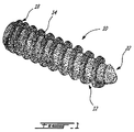
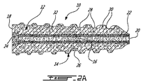
ここで図1を参照すると、本開示の1つの実施形態による注入用ねじ10を示している。この実施形態では、注入用骨ねじ10が、一体形成された一体型ボディとすることができる、外周面上に少なくとも1つの雄ねじ14を有するねじ本体12を含む。図2Aで分かるように、ねじ本体12のヘッド端部18とカニューレ挿入通路16の先端部開口部20との間には、注入用骨ねじ10の全長を通じて非円形断面、より正確には少なくともこの特定の実施形態では六角形を有する中心カニューレ挿入通路16が長手方向に延びる。図2Bで最もよく分かるように、注入用ねじ10のカニューレ挿入通路16は非円形断面を有し、少なくとも1つの実施形態ではやはり六角形を定める。カニューレ挿入通路16には、本明細書でさらに詳述する非円形断面を有するガイドワイヤが挿入され、この非円形断面がガイドワイヤとねじを共に回転的に相互接続し、例えば手術中に注入用骨ねじ10を骨又は適所に挿入した時に、ガイドワイヤとねじが相対的に軸回転するのを防ぐようになる。
Referring now to FIG. 1, an
ある実施形態では、以下でさらに詳細に説明するように、注入用ねじ10がアダプタ開口部24を含み、このアダプタ開口部24の直径は、カニューレ挿入通路16の直径よりも大きく、注入器又はシリンジ100と注入用骨ねじ10のカニューレ挿入通路16とを流体的に相互接続するために使用するアダプタを受け入れるようなサイズ及び構成とすることができる。ねじ本体12のカニューレ挿入通路16は、シリンジ100と骨ねじ14が流体流連通して接続された時(図7A及び図7B)にシリンジ100からの流体を受け取る入口端部を定める。
In certain embodiments, as will be described in more detail below, the
図2A〜図2Bの実施形態では、注入用骨ねじ10のねじ本体12は、一体型又はモノリシック型である(すなわち、単一の材料片から一体形成される)が、このモノリシック型ねじ本体12の特性は、必ずしも全体を通じて均一であるとは限らない。それでも、ねじ本体12は、必然的に少なくとも部分的に透過性であり、ねじ本体12のカニューレ挿入通路16から外面26まで延びる、ねじ本体12を貫く1又はそれ以上の流体放出路28を定める。注入用骨ねじ10では、ねじ本体12全体を通じて相互接続され配置された複数の細孔30により、複数のこれらの流体放出路28が提供され定められる。従って、注入用骨ねじ10のねじ本体12は、注入用骨ねじ10が全体を通じて多孔性であるように、実際には完全に多孔性の材料で構成される。これらの細孔30を相互接続して、ねじ本体12のカニューレ挿入通路16を取り囲む環状部分34の半径方向の壁厚全体を通じて泡状基質を定める。注入用骨ねじ10は、例えば複数の細孔30をもたらす実質的に硬質の発泡材料から作製し、これらの細孔30が相互接続されて、注入用骨ねじ10のねじ本体12を通じて延びる複数の流体放出路28を形成することにより、シリンジ100によって注入用骨ねじ10のカニューレ挿入通路16に注入された粘性媒質が、ねじ本体12のこれらの通路28を通って周囲環境に、すなわち注入用骨ねじ10が位置する組織に流入できるようにすることができる。
In the embodiment of FIGS. 2A-2B, the
本明細書で定義するねじは、2010年10月13日に出願された国際特許出願第PCT/CA2010/001645号に定義される骨ねじと同様に構成及び/又は形成することができ、この特許出願の内容全体が引用により本明細書に組み入れられる。 The screws defined herein may be configured and / or formed in a manner similar to bone screws as defined in International Patent Application No. PCT / CA2010 / 001645 filed on October 13, 2010. The entire contents of the application are incorporated herein by reference.
従って、本開示の注入用骨ねじ10は、実際には、例えばねじを取り巻く組織、又はねじを挿入する骨折骨の断面間に形成されることがある近隣の隙間に粘性媒質又は流体を注入するための注入器として使用される。
Thus, the
1つの考えられる実施形態では、注入用骨ねじ10の相互接続された細孔30により、何らかの骨又はその他の組織がねじ本体内に内方成長し、これによりねじ内に固定されたこれらの骨又はその他の組織内のねじが占める空間を最小化できる可能性もある。しかしながら、この組織又は骨の内方成長は、細孔30、従って注入用骨ねじ10内に形成された流体放出路28を介して上述の粘性媒質が周囲組織に注入された後にのみ生じ得ると理解されたい。しかしながら、別の実施形態では、細孔30を、実際にあらゆる骨又は組織の内方成長を防ぐほど十分に小さくする一方で、それでもねじの挿入後にねじを通じて粘性媒質の注入を可能にするようなサイズにすることができる。この実施形態については、以下でさらに詳細に説明する。
In one possible embodiment, the interconnected pores 30 of the injecting
図2A〜図2Bに示す注入用骨ねじ10は、骨ねじを差し込む2つの骨折骨部分を共に圧縮するように、外周上に形成されるスレッド14のピッチを様々とする圧縮骨ねじである。図示の骨ねじ10にはたまたまヘッド部が無いものの、ヘッド部を有している状態で、骨修復促進材料、又は抗生物質、又は抗癌剤、或いは骨に影響を与える状態を治療するためのその他のあらゆる薬剤又は化合物などの粘性媒質を周囲の組織部位に注入するための注入器として使用することもできるが、当然ながらこのことは、ねじに望まれる特定の用途に依存する。
The
上述したように、注入用骨ねじ10は、例えば、内部に複数の相互接続された細孔30を形成する基質を定める硬質発泡体により少なくとも部分的に形成することができる。これらの細孔は相互接続されて、ねじ本体12の全体を通じて複数の流体放出路28を形成し、粘性媒質がカニューレ挿入通路16内からねじ本体12の環状壁部分32を通じて周囲の環境組織内に外向きに流れるようにする。骨ねじ10は、上述した硬質発泡体により全体的に形成され全体を通じて多孔性であるように示しているが、実際にはねじ本体の一部のみが、相互接続された細孔30、従って流体放出路28を内部に有することができ、従ってねじ本体の一部のみをこのような硬質発泡体により形成することもできると理解されたい。硬質発泡体は、相互接続されることにより粘性媒質がねじの本体を通じてその周囲環境に外向きに流れるようにする流体放出路を定める細孔を内部に形成する多孔性金属、セラミック又はポリマー材料で構成することができる。
As described above, the
本明細書で説明する多孔性ねじ本体12部分の細孔30は、相互接続されて複数の相互接続された空隙を形成し、これらの空隙の各々は、次の隣接する空隙と連通するとともに、ねじ10の所与の多孔性部分の全ての方向に、及びねじ10の外面からその内部のカニューレ挿入通路16まで少なくとも半径方向に実質的に均一に延びる。少なくとも1つの特定の実施形態では、細孔30が、骨ねじ10を形成するために使用する生産工程に基づいて合理的に実現可能な程度に、実質的に均一なサイズにされるとともに、実質的に均一に離間する。しかしながら、本明細書で説明する注入用骨ねじ10を構成する硬質発泡材料の細孔30は、必ずしも同じサイズを有し、或いは等しく又は均一に離間する必要はないと理解されたい。硬質発泡体は、必ずしも金属発泡体で構成される必要はなく、例えば、粉末冶金技術を使用して金属粉末から作製された多孔性焼結金属で構成することもできる。金属発泡体は、チタン、マグネシウム、鉄、タンタル、或いはステンレス鋼、Ti6A14V、TiNI又はセラミックなどの1又はそれ以上のこれらの合金を含むことができる。金属発泡材料は、全体を通じて相互接続された細孔30を定める金属マトリクス又はネットワークを形成する。この相互接続された多孔性により、ねじ本体12の片側から反対側への流体流が可能になり、従って完全な骨の内方成長が可能になる(実際には骨の貫通成長が可能になる)。このことは、例えば、互いに及び部品の両面と接続されていない(例えば、固体金属部品に機械加工又は別様に形成された)孤立した表面細孔とは対照的である。1つの実施形態では、この多孔性材料が、例えばチタン合金で作製された金属発泡体である。当然ながら他の範囲も可能ではあるが、細孔28は、少なくとも1つの実施形態では約30〜約500ミクロン(すなわち、μm)のサイズを有し、ただし所望のレベルの骨の内方成長及び機械的強度を達成するには50〜400μmのサイズ(例えば、直径)を有することが好ましく、多孔性材料は、30%〜80%の気孔率を有し、ただし所望のレベルの機械的強度を得るには40〜70%の気孔率を有することが好ましい。別の考えられる実施形態では、細孔及び/又は流体流路が、5〜2000ミクロンの断面サイズ(すなわち、例えば円形開口部の幅、或いは直径などの少なくとも一方向のサイズ)を有し、この断面サイズは、10〜1000ミクロンであることがより好ましく、30〜500ミクロンであることがより好ましく、さらには50〜400ミクロンであることがより好ましい。
The pores 30 of the
言うまでもなく、骨ねじ10のために選択する材料は生体適合性がなければならず、必須ではないが非強磁性とし、従って骨の磁気共鳴撮像(MRI)を可能にしてもよい。
Of course, the material selected for the
従って、骨ねじ10は、骨ねじ10を挿入する周囲の骨又は組織に注入することが望まれる粘性材料に対して少なくとも部分的に透過性を有するように形成される。従って、細孔30及び/又は流体放出路28のサイズ、並びに注入すべき材料の粘稠性及び粘性は、材料がねじ本体12を通じて周囲組織に外向きに流入できるように選択される。これを使用して、例えば、骨ねじ10が位置する骨に存在している骨折箇所に粘性媒質を注入し、これにより、骨、又は骨に接合される必要があるその他の組織間に骨ねじ10を挿入又は配置することができる。従って、粘性媒質の骨折部位への注入を行って骨折の隙間を少なくとも部分的に満たし、これにより骨折した両側の骨の安定性を高め、及び/又は骨片間の又は骨とその他の組織との間の融合を促す。これとは別に、隣接する骨を融合するのを手助けするために、これらの骨の間で注入用骨ねじ10を使用し、これにより2つの骨の間に形成された隙間に粘性媒質を注入することで、これらの骨の安定性を高め又はこれらの骨を結合する役に立てることができる。同様に、注入器又はシリンジ100を伴った骨ねじ10を使用して、骨に接続される必要があるより柔らかい結合組織に粘性媒質を注入することもできる。従って、粘性媒質の注入により、ねじ10と周囲組織の隙間を少なくとも部分的に満たして、回復及び固定を促す役に立てることができる。
Accordingly, the
この注入用ねじ10を使用して周囲の骨又は組織に粘性媒質を注入することに関してはいくつかの利用可能性が存在するが、1つの考えられる実施形態では、この注入用ねじ10を、撮像用のトレーサを含む粘性媒質を注入するために使用することができる。例えば、X線を使用した問題のある組織の撮像を改善するために、このねじ10を使用して、酸化バリウムを含む媒質を周囲組織に注入することができる。当然ながら、X線の撮像又はその他の撮像技術のために、酸化バリウムの代わりに他のトレーサを使用することもできる。
Although there are several possibilities for injecting a viscous medium into the surrounding bone or tissue using the
骨ねじ10のねじ本体12の多孔性は、ねじ10のカニューレ挿入通路16と外面26の間の流体流を可能にするように、相互接続された細孔08により形成された流体放出路28を通じた粘性媒質の流れ、従って注入を可能にしなければならないようなものとする。しかしながら、1つの特定の実施形態では、例えば、最終的にはこれらのねじを取り外す必要があるという点で、ねじ本体12の細孔30内への周囲組織の内方成長を防ぐ必要がある。このような場合、ねじ本体12を形成するために使用する材料は、内部に定められる細孔30が、ねじ本体12を通じて流れる選択した粘性媒質を周囲組織に注入できるほど十分に大きなものであると同時に、ねじ本体12を挿入した後にその細孔30内に周囲組織が成長して入り込むのを防ぐほど十分に小さいものであるように選択される。例えば、1つの考えられる実施形態では、細孔30が、骨の内方成長を防ぐと同時に、相互接続された細孔30を流体が貫流し、従ってこれらの細孔30によってねじ10内に形成される通路から粘性媒質を放出できるほど十分に小さな15ミクロン未満のサイズを有することができる。
The porosity of the
上述したように、骨ねじ10の挿入後には、粘性媒質を、内部カニューレからねじ10の細孔30に外向きに含浸させるために、シリンジ100によってねじのカニューレ挿入通路16に注入する。従って、骨ねじ10は、粘性媒質に対して透過性を有し、これにより骨ねじ10から骨又は周囲組織内の原位置において粘性媒質が放出される。このねじ10内の粘性媒質の注入は、骨折の隙間を少なくとも部分的に満たして骨折の両側の骨の安定性を高め、又は骨片間の融合を促すように行うことができる。ねじ10内の粘性媒質の注入は、隣接する骨の間の隙間を少なくとも部分的に満たしてこれらの安定性を高め、又はこれらを融合させるように行うこともできる。隙間内への媒質の注入は、ねじ10とねじ10に接触している組織との間の隙間を少なくとも部分的に満たして、このような腱、靭帯又は軟骨などの組織の回復及び固定を促すように行うこともできる。粘性媒質は、周囲組織内で拡散して、ねじ10を取り巻く組織を回復させるように行うこともできる。しかしながら、全ての場合において、媒質の粘性は、ねじ10の多孔性を通じて注入できるようなものでなければならない。媒質(例えば、脱灰した骨基質、リン酸カルシウム、リン酸三カルシウム、ヒドロキシアパタイト、バイオガラス粒子又はトレーサ粒子)に電荷が存在する場合、これらの粒子サイズは、注入用骨ねじ10の細孔30及び/又はカニューレ挿入通路を少なくとも部分的に貫流できるようなものでなければならない。
As described above, after insertion of the
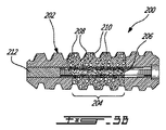
ここで図3A〜図3Bを参照すると、代替の実施形態による注入用骨ねじ200を示している。骨ねじ200は、上述した骨ねじ10と実質的に同じ物であるが、図3Bで最もよく分かるように、この骨ねじ200は、例えばねじの中央部分204などの、ねじの一部又は領域のみが多孔性であるねじ本体202を定める。従って、ねじ本体202は、カニューレ挿入通路206に注入される粘性材料に対して透過性を保つが、これは、複数の細孔208が設けられ、これらが相互接続して、骨ねじ200を通じて放出すべき粘性流体のための流体放出路210を形成するこの中央部204のみに限られる。図3A〜図3Bに示す実施形態では、骨ねじ200の中央部分204のみが多孔性であるが、中心部分の代わりに骨ねじ200のその他の領域を多孔性にすることも可能である。例えば、骨ねじの両端部から粘性材料を放出できるようになっている一方で、骨ねじの中心部分が実質的に固体のままとされ、細孔及び/又は流体放出路を有していない骨ねじを提供することが望ましいこともある。
Referring now to FIGS. 3A-3B, an
従って、注入用骨ねじの構成を、使用を意図する特定の環境又は用途に適するように調整し、これにより選択した粘性媒質を周囲組織の望ましい場所にのみ制御的かつ局所的に注入できるようにすることができる。骨ねじ200は、ねじ本体202の長さに少なくとも部分的に沿って延びる通路206を含むが、この通路206は、ねじ200の全長には延びず、従って一方の端部は閉じられている(すなわち、このねじは、部分的にしかカニューレ挿入されていない)。この構造は、製造時にねじ本体内にボアが部分的にしか延びないように骨ねじ200を形成することにより、或いは、最初に環状通路206をねじ本体202の全長に延びるように形成し、例えば環状通路206の一端を密閉することが望ましい場合には、後で環状通路206に挿入されるボアプラグ212により後から密封することにより実現することができる。このボアプラグ212を骨ねじ200の環状通路206に挿入するのは、骨ねじ200を周囲組織に挿入する前であっても、又は挿入した後であってもよい。
Therefore, the configuration of the bone screw for injection is adjusted to suit the particular environment or application intended for use so that the selected viscous medium can be controlled and locally injected only into the desired location of the surrounding tissue. can do. The
本明細書で説明する骨ねじ300のさらに別の実施形態として、図6に、周囲組織に注入すべき粘性媒質に対して少なくとも部分的に透過性を保つ骨ねじ300を示しており、この骨ねじ300は、実質的に固体ではあるが、わずかな数の流体放出路306を内部に定めるねじ本体302を有するように形成され、この流体放出路306は、ねじ本体302の環状体部分304を貫いて環状通路310と骨ねじ300の外周上の外面312との間に延びる。骨ねじ300の環状通路310は、上述した注入用骨ねじ10及び200とほぼ同様に、環状通路310と、骨ねじ300が挿入される周囲組織との間の流体流連通を可能にし、骨ねじ300のアダプタ開口部314にシリンジ100を接続することによって骨ねじ300の環状通路310に粘性媒質が注入されると、この粘性媒質が環状通路310内に押し出され、その後ねじ本体302の流体放出路306を通じて外に、従って周囲組織内に押し出されるようになる。しかしながら、この実施形態では、ねじ本体302は、多孔性構造により形成されておらず、個別に形成された流体放出路306を内部に有する単純な固体ねじ本体しか含まなくてよい。これらの通路は、機械加工又は別の成形工程などによりねじ本体の形成と同時に形成することも、或いは骨ねじ300の製造中に機械加工又はエッチング工程などを使用することにより、通路306を別個に形成することもできる。
As yet another embodiment of the bone screw 300 described herein, FIG. 6 illustrates a bone screw 300 that remains at least partially permeable to a viscous medium to be injected into surrounding tissue. The screw 300 is formed to have a screw body 302 that is substantially solid but defines a small number of fluid discharge passages 306 therein, the fluid discharge passages 306 defining the annular body portion 304 of the screw body 302. It extends between the annular passage 310 and the outer surface 312 on the outer periphery of the bone screw 300. The annular passage 310 of the bone screw 300 enables fluid flow communication between the annular passage 310 and the surrounding tissue into which the bone screw 300 is inserted, much like the bone screws 10 and 200 for injection described above. When a viscous medium is injected into the annular passage 310 of the bone screw 300 by connecting the
上述した骨ねじ、及びこの骨ねじを使用した骨治療用流体の注入に使用される関連方法及びシステムはいくつかの方法で挿入することができるが、以下、骨の中に骨ねじを挿入するために使用できる1つの特定の方法について説明する。以下で説明する導入法は、ガイドワイヤを使用して、完全にカニューレ挿入された骨ねじの実施形態を骨部位に導入することに関するが、他の導入及び挿入技術も使用できると理解される。例えば、部分的にカニューレ挿入された(すなわち、中心ボア又はカニューレがねじの長さ全体にわたって延びていない)ねじの場合、上述したガイドワイヤは使用されない。このような不完全にカニューレ挿入された骨ねじを導入するためにも使用できる代替の導入技術としては、例えばカニューレ開口部と同じ形状を有する、又はねじのヘッド部と係合した従来のねじ回しと同じ形状を有するねじ回しを使用することを含む。 The bone screw described above and the related methods and systems used for injecting bone treatment fluids using this bone screw can be inserted in several ways, hereinafter the bone screw is inserted into the bone. One particular method that can be used for this purpose will be described. The introduction method described below relates to introducing a fully cannulated bone screw embodiment into a bone site using a guidewire, but it will be understood that other introduction and insertion techniques may be used. For example, in the case of screws that are partially cannulated (ie, the central bore or cannula does not extend the entire length of the screw), the guidewire described above is not used. Alternative introduction techniques that can also be used to introduce such incompletely cannulated bone screws include, for example, conventional screwdrivers having the same shape as the cannula opening or engaged with the screw head. And using a screwdriver having the same shape.
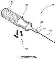
ここで図5A及び図5Bを参照すると、一般にガイドワイヤ402及び本明細書で説明したような少なくとも1つの注入用骨ねじ10を含むねじ挿入システム/キット400を示している。関連する駆動要素としては、ねじ10を挿入するために使用される駆動ハンドル406が含まれ、この駆動ハンドル406は、その長手方向軸を中心にガイドワイヤを回転させるように、ガイドワイヤと取り外し可能に係合する。上述したように、ガイドワイヤ402は、非円形の横断面形状を有する。この実施形態では、ガイドワイヤ402が、図6Aに関連して以下でさらに詳細に説明するように六角形を定める。ねじ10のカニューレ挿入通路16も同じ非円形断面を有し、少なくともこの特定の実施形態では、図1及び図2Bでより良く理解されるように同じく六角形を定める。
Referring now to FIGS. 5A and 5B, there is shown a screw insertion system /
従って、図5Bでより良く理解されるように、この六角形のガイドワイヤ402をねじ10の六角形のカニューレ挿入通路16に挿入して、ガイドワイヤ402がねじ10と相互に及び対応して回転するように係合させることができる。換言すれば、ねじ10のカニューレ挿入通路16及び嵌合ガイドワイヤ402の両方の非円形形状は、ガイドワイヤ402が回転することによりねじ10が同様に対応して回転するようなものとされる。ねじのカニューレ挿入通路16及びガイドワイヤ402の断面形状のサイズは、ねじ10のカニューレ挿入通路16内でガイドワイヤが回転できないように構成される。例えば、カニューレ挿入通路16の内側サイズ及び形状は、ガイドワイヤ402の外側の非円形構成とぴったり嵌まり合い、ガイドワイヤ402が回転すると、これに応じてねじ10も回転するようになる。
Thus, as better understood in FIG. 5B, this
ハンドル又は駆動要素406は、図5Aで最もよく分かるように、ガイドワイヤ402を嵌合的に受け入れるように成形され構成されたカニューレ開口部410を内部に有する駆動端408を含み、従ってこのカニューレ開口部410の形状も非円形である。カニューレ開口部410は、駆動要素406内の中心に配置することができるが、必ずしもハンドル本体の全長に延びているとは限らない。理解されるように、駆動要素406はねじ回しとして機能し、そのねじ回しの「ビット」がガイドワイヤ402である。従って、駆動要素406は、ユーザが駆動要素406の長手方向軸を中心にハンドルを回せるようにするグリップ部412を含み、この長手方向軸は、内部に受け入れられたガイドワイヤ402を駆動するように、内部のカニューレ410と同軸上に存在することができる。
The handle or drive
従って、ガイドワイヤ402は、ねじ10のカニューレ挿入通路16及び駆動要素406のカニューレ開口部410の両方に挿入することができる。図示の実施形態では、ガイドワイヤ402、ねじのカニューレ挿入通路16及びハンドルのカニューレ410の断面形状が全て同一である。しかしながら、後述するように、ガイドワイヤ402及びカニューレ挿入通路16のそれぞれの断面形状が、ガイドワイヤ402がカニューレ挿入通路16内にぴったりと収まって、ガイドワイヤ402とねじ10及び/又は駆動要素406の相対的回転を許容しないように協働するのであれば、これらの断面形状は異なってもよい。
Thus, the
従って、ガイドワイヤ402、ねじ14のカニューレ挿入通路16及びカニューレ410の断面は全て円形でないので、ガイドワイヤ402は、ねじ10又は駆動要素402内で自由に回転することができない。従って、ガイドワイヤ402がねじ10のカニューレ挿入通路16に挿入されると、ガイドワイヤ402をハンドル又は駆動要素406に挿入した時にハンドル又は駆動要素406を回転させることによってガイドワイヤ402を回転させることにより、ねじが組織内にねじ込まれるようになる。従って、駆動要素406を回転させることにより、骨、軟組織などの組織に注入用骨ねじ10を挿入することができ、駆動要素406と注入用骨ねじ10の間に配置されたガイドワイヤ402が、(例えば、取り外し可能なねじ回しビットに酷似する)ねじり力伝達要素として機能する。駆動要素406の先端部408を使用してねじ10に圧力を印加し、その挿入を容易にすることができる。
Thus, the
駆動要素406の先端部408及びねじ10のヘッド端部18を、ガイドワイヤ402とさらに係合するようにテクスチャ加工又は成形して、組織内へのねじの挿入中におけるガイドワイヤ402のねじり応力及び変形をさらに低減することもできる。このような特徴は、例えば、階段形、六角形の突起、十字形、星形又はフィンを含むことができる。
The
図5A及び図5Bに示すねじ挿入システム/キット400は、ねじ10を手動挿入するための手動操作用ハンドツールであるハンドルの形をとる駆動要素406を含むが、この使用する駆動ハンドル又は駆動要素は、ねじ10を挿入するためのガイドワイヤ402を把持して回転させることができる機械又は電気システムを含むこともできる。駆動要素又はハンドル406内のカニューレ410を使用することは、ガイドワイヤ402を駆動するための単純な解決策であるが、他の方法を使用してハンドル406内にガイドワイヤ402を固定することもできる。言うまでもなく、ガイドワイヤ及びハンドル内のカニューレのサイズは、ねじのタイプ及びサイズに適応させることができると理解されたい。
The screw insertion system /
ガイドワイヤ402は、従来のガイドワイヤとほぼ同様にねじの挿入を導くような、注入用骨ねじ10を沿わせて摺動できるガイドとして使用される。しかしながら、この非円形のガイドワイヤ402は、ねじ10を骨及び/又はその他の組織に差し込むためのドライバとしても使用される。このガイドワイヤ402及び内部に非円形のカニューレ挿入通路16を有する関連するねじ10の非円形の断面形状(例えば、図6A及び図6Bを参照)は、注入用ねじ10の挿入中における応力の低減を可能にする構成をもたらす。本明細書で説明するシステム及び方法は、本明細書に含まれる全てのタイプの注入用ねじに使用できるが、ポリマー、セラミックス及び/又は多孔性材料で作製されたような、機械的特性の低いねじの挿入に特に有用となり得る。
この非円形カニューレ挿入通路16を有するねじ10を対応する非円形ガイドワイヤ402と共に使用することは、一般に既知の円形ガイドワイヤ及びカニューレ挿入ねじの使用時に直面する重要な技術的課題を克服する役に立つ。その理由は、生物医学用途で使用するねじの直径が非常に小さく、従って既知の装置でよく行われているように、ねじを差し込むためにねじカニューレの全長内にガイドワイヤとねじ回しを両方同時に挿入できるようにすることが非常に困難なためである。しかしながら、この問題は、このシステム/キット10及びこのようなツールを使用してねじを挿入する方法により解決される。
Using the
ここで再び図6Aを参照すると、ガイドワイヤ402は、その全長に沿って六角形の断面形状を有する。この実施形態では、ガイドワイヤ402の断面形状がワイヤの全長を通じて均一であるが、これとは別に、ガイドワイヤによりねじを係合させて駆動できるのであれば、断面はその長さに沿って変化してもよい。しかしながら、ガイドワイヤの断面形状は、ねじのカニューレ挿入通路の断面と同じにものされる。
Referring again to FIG. 6A, the
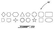
図6Bに、六角形断面の他にも使用できる、ガイドワイヤ402の他のいくつかの断面形状を示す。図6Bには、考えられる非円形断面ガイドワイヤの形状の複数の例を示しているが、ガイドワイヤをねじ内に係合でき、ねじのカニューレ内で自由に回転できないようにする限り、いずれのタイプの非円形断面を使用してもよいと理解されたい。ガイドワイヤの断面は、例えば、六角形、八角形、五角形、三角形、正方形、十字形、星形、長円形、これらのあらゆる組み合わせ、又はねじのカニューレ内部でガイドワイヤが回転できないようにする他のあらゆる断面形状とすることができる。
FIG. 6B shows several other cross-sectional shapes of
現在示している実施形態では、ねじ10のカニューレ挿入通路16の断面形状が、ガイドワイヤ402の形状に一致する。しかしながら、ねじにガイドワイヤを挿入でき、ねじを組織に挿入するためにガイドワイヤがねじの回転と係合できるようにしてねじ内で自由に回転できない限り、ガイドワイヤの断面形状はねじの断面形状と異なってもよい。例えば、ガイドワイヤがX字形の断面を有し、これを同じ対角線の正方形の断面を有するカニューレに挿入することもできる。
In the presently shown embodiment, the cross-sectional shape of the
ガイドワイヤ402は、挿入しやすいように硬質にすることができる。挿入位置と直接的に見通し線内にない部位にアクセスするために、多少の柔軟性を有するガイドワイヤを使用することもできる。ガイドワイヤの直径は、ねじのサイズに応じて0.5mm〜5mmとすることができる。ガイドワイヤは、中空又は有孔であってもよい。
The
本明細書で上述した挿入キットを使用して、注入用ねじが骨内の適所に挿入されると、これから説明する注入キット、システム及び/又は方法を使用して、骨修復促進流体を骨部位に注入することができる。 Once the injection screw has been inserted into place in the bone using the insertion kit described herein above, the bone repair promoting fluid is delivered to the bone site using the injection kit, system and / or method described below. Can be injected into.
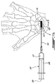
ここで図7A及び図7Bを参照すると、上述した注入用ねじ10を使用して、患者の手首の舟状骨の骨折部位に骨治療用流体を注入する様子を示している。1つの特定の実施形態では、注入用骨ねじ10の入口端部が流体注入器100に係合し、互いに流体流連通して接続できるように構成される。流体注入器100は、円筒形リザーバ部108を有するシリンジ、及び遠端部に注入器先端部112を有する細長い針部分110で構成することができる。
Referring now to FIGS. 7A and 7B, a bone treatment fluid is injected into the scaphoid fracture site of the patient's wrist using the
図2A〜図2Bで最もよく分かるように、骨ねじ10の本体12のヘッド部18のアダプタ開口部24は、カニューレ挿入通路16の直径よりも大きな直径を有するように形成されるとともに、流体注入器又はシリンジ100の注入先端部112を内部に嵌合的に受け入れるように形成され構成される。1つの考えられる実施形態では、アダプタ開口部24が、注入器先端部112との間に締まり嵌めを形成して、注入過程中にこれらの両方が結合され嵌合接触した状態で流体注入器が作動して、流体注入器100から骨ねじ10のカニューレ挿入通路16内に粘性材料を送り込むようになる。流体注入器の注入器先端部112が注入用骨ねじと嵌合的に結合し、従ってこれらの一方から他方に粘性材料を移動できるようにするために、追加のコネクタ又はその他の急速結合タイプの部品又は機構を骨ねじ10のヘッド部18上にさらに設けることができる。
As best seen in FIGS. 2A-2B, the
別の実施形態では、流体注入器100の注入器先端部112が、アダプタを全く必要とせずに、又は注入器先端部と骨ねじの間の嵌合接続を伴わずに骨ねじに直接接続することができる。例えば、注入器先端部112を、ねじの上部に直接密封することができる。この場合、流体注入器110と骨ねじ10を相互接続するためにアダプタを必要とせずに、又は注入器先端部112がねじ10に接続できるようにするために、ねじ本体12内の少なくともアダプタ開口部を必要とせずに、依然として流体注入器100が内部の流体を骨ねじ10のカニューレ挿入通路16に注入できるようにすることができる。
In another embodiment, the
図7Aに示すように、ねじ10が骨に挿入されると、図7Bに示すように、流体注入器100の注入器先端部112を、骨ねじ10の露出端部におけるアダプタ開口部24に嵌合係合させて接続することができる。流体注入器100がねじ10に接続されると、シリンジリザーバ108(図7Aを参照)のプランジャ109を押圧することなどにより、骨ねじ10を取り巻く骨及び/又は領域に粘性流体を注入するように流体注入器100を作動させ、これによりリザーバ108から流体注入器100の針部分110を通じて骨ねじ10のカニューレ挿入通路16内に(例えば、骨治療用流体などの)粘性流体を送り込むことができる。その後、この粘性流体は、ねじ本体12の流体放出路28を通じて(或いはねじ本体12内の相互接続された細孔などを通じて)、カニューレ挿入通路16からねじ10の外面26を取り巻く骨に移動する。このようにして、粘性流体は、挿入キット400を使用して骨B内の原位置に配置された注入用骨ねじ10を介して骨に注入され、従って骨ねじ10は、注入すべき流体のための埋め込み型注入装置として機能する。
As shown in FIG. 7A, when the
従って、上述した方法を使用して、例えば図7A及び図7Bに示すように、骨ねじ10を、舟状骨Sの骨折箇所120をまたぐように舟状骨「S」内に位置決めして挿入する。材料又は粘性流体は、流体注入器100によって骨ねじ10内に送り込まれると、骨ねじ10のカニューレ挿入通路16(図7Bを参照)を通じて骨Sの骨折亀裂120に注入される。従って、流体注入器100と骨ねじ10の組み合わせは、別の方法ではアクセスするのも困難な骨又はその他の組織内に内部から粘性媒質を直接注入できるようにする流体注入装置キットを提供する。隣接する骨片が完全に接触していない状態を再現するように意図的に隙間を残した骨折した舟状骨Sにおいて行った試験では、ねじ10に注入された粘性媒質が、材料の多孔性部分を貫流し、舟状骨Sの骨折の隙間120に流れ込むことができた。
Therefore, using the above-described method, for example, as shown in FIGS. 7A and 7B, the
現在説明している骨ねじのために選択される(単複の)材料は、完全に生体適合性があり、人及び動物内の骨折固定に関連して使用するのに適したようなものであると理解されたい。 The material (s) selected for the bone screws currently described are fully biocompatible and are suitable for use in connection with fracture fixation in humans and animals. Please understand.
本明細書において、この圧縮ねじの形成材料である発泡材料に関して使用する「硬質」という用語は、構造的に自立していること、及び適当な駆動装置(例えば、電動又は手動ねじ回し)を使用した骨要素への挿入(及び骨要素からの除去)に、曲げ又は実質的な偏向又は圧縮などを伴わずに耐えるほど十分に強いものである(例えば、十分なねじり剛性を有する)ことを意味すると理解されたい。 As used herein, the term “hard” as used with respect to the foam material that forms the compression screw is structurally self-supporting and uses an appropriate drive (eg, electric or manual screwdriver). Means sufficiently strong to withstand insertion (and removal from a bone element) without bending or substantial deflection or compression (eg, having sufficient torsional rigidity) Then I want you to understand.
上記の説明は、ほんの一例であることを意図するものであり、当業者であれば、開示する本発明の範囲から逸脱することなく、説明する実施形態に変更を加えることができると認識するであろう。当業者には、本開示の再検討を踏まえると、本発明の範囲に含まれるさらに他の修正が明らかになると思われ、このような修正は、添付の特許請求の範囲内に含まれることが意図される。 The above description is intended to be exemplary only, and one of ordinary skill in the art will recognize that changes can be made to the described embodiments without departing from the scope of the disclosed invention. I will. Those skilled in the art will appreciate further modifications that are within the scope of the invention in light of a review of the disclosure and that such modifications may be included within the scope of the appended claims. Intended.
10 注入用骨ねじ
100 流体注入器(シリンジ)
108 リザーバ
109 プランジャ
110 針部分
112 注入器先端部
120 骨折箇所
122 粘性媒質
S 舟状骨
10
108
Claims (44)
流体注入器を備え、該流体注入器は、注入器先端部と流体連通している、前記流体のための貯蔵リザーバを有し、前記流体注入器の作動時には、前記注入器先端部から前記流体が放出され、前記システムは、
外面上に少なくとも1つの雄ねじを有するねじ本体と、入口端部における開口部から前記ねじ本体内に少なくとも部分的に延びる中心ボアとを有する骨ねじをさらに備え、
前記中心ボアへの前記開口部は、前記流体注入器の前記注入器先端部を嵌合状態で内部に受け入れて、前記流体注入器と前記骨ねじが流体連通して接続された時に、前記流体注入器からの前記流体が前記中心ボア内に供給されるように構成され、前記骨ねじが前記骨に挿入されて前記流体注入器により前記骨ねじに流体が注入された時に前記中心ボア内から前記骨ねじを取り巻く前記骨まで外向きに流体流を供給する1又はそれ以上の流体放出路が、前記ねじ本体の前記中心ボアから前記外面に前記ねじ本体を貫いて延びる、
ことを特徴とするシステム。 A system for injecting fluid into bone,
A fluid reservoir, the fluid injector having a storage reservoir for the fluid in fluid communication with the injector tip, and when the fluid injector is in operation, the fluid injector from the injector tip Is released and the system is
A bone screw having a screw body having at least one external thread on the outer surface and a central bore extending at least partially into the screw body from an opening at the inlet end;
The opening to the central bore receives the injector tip of the fluid injector in a mated state therein, and when the fluid injector and the bone screw are connected in fluid communication, the fluid The fluid from an injector is configured to be supplied into the central bore, and when the bone screw is inserted into the bone and fluid is injected into the bone screw by the fluid injector, from within the central bore One or more fluid discharge passages that supply fluid flow outwardly to the bone surrounding the bone screw extend from the central bore of the screw body through the screw body to the outer surface.
A system characterized by that.
ことを特徴とする請求項1に記載のシステム。 The fluid injector includes a syringe having a cylindrical reservoir portion, from which an elongated needle portion having the injector tip extends at a distal end, the cylindrical reservoir portion of the fluid injector. Forming the storage reservoir;
The system according to claim 1.
ことを特徴とする請求項1に記載のシステム。 The screw body has an annular portion surrounding the central bore and having a radial wall thickness, and the fluid discharge path is defined at least within the annular portion, and the radial wall thickness of the annular portion is defined. Extending through,
The system according to claim 1.
ことを特徴とする請求項1に記載のシステム。 The screw body is at least partially constructed of a rigid foam defining a substrate that internally defines a plurality of interconnected pores, the interconnected pores disposed throughout the radial wall thickness. Defining the fluid discharge path,
The system according to claim 1.
ことを特徴とする請求項4に記載のシステム。 The hard foam is a porous sintered metal made from metal powder using powder metallurgy, and the hard metal foam forms a metal matrix that defines the pores throughout.
The system according to claim 4.
ことを特徴とする請求項5に記載のシステム。 The hard metal foam includes titanium, tantalum, magnesium, iron, or any one or more alloys thereof.
The system according to claim 5.
ことを特徴とする請求項4に記載のシステム。 The fluid flow path allows fluid to continue to flow outwardly through the fluid flow path while being small enough to prevent bone ingrowth, less than 15 microns, 5 to 2000 microns, 10 to 1000. Having a cross-sectional size of micron, 30-500 microns, or 50-400 microns,
The system according to claim 4.
ことを特徴とする請求項1に記載のシステム。 The bone screw is a headless compression screw, and the screw body includes at least a threaded front end and a threaded rear end, the threaded front end having a pitch greater than the pitch of the rear end. ,
The system according to claim 1.
前記ガイドワイヤと係合して、該ガイドワイヤを、前記長手方向軸を中心に回転させるように構成された駆動要素と、
をさらに含み、
前記ねじ本体の前記中心ボアは、前記骨ねじが完全にカニューレ挿入されるように前記ねじ本体の長手方向の全長に延びるとともに、前記ガイドワイヤが前記骨ねじの前記中心ボアと嵌合している時に、前記ガイドワイヤと回転的に相互接続して、前記ガイドワイヤと前記整形外科用ねじの間の相対的軸回転を防ぐように構成された非円形横断面形状を有し、
これにより前記駆動要素を使用して前記長手方向軸を中心に前記ガイドワイヤを回転させると、前記ガイドワイヤに結合された前記骨ねじを回転させるように作用する、
ことを特徴とする請求項1に記載のシステム。 A guide wire having a longitudinal axis and defining a non-circular cross-sectional shape;
A drive element configured to engage the guidewire and rotate the guidewire about the longitudinal axis;
Further including
The central bore of the screw body extends the entire length of the screw body so that the bone screw is fully cannulated, and the guide wire is engaged with the central bore of the bone screw. Sometimes having a non-circular cross-sectional shape configured to rotationally interconnect with the guide wire to prevent relative axial rotation between the guide wire and the orthopedic screw;
Thereby, using the drive element to rotate the guide wire about the longitudinal axis acts to rotate the bone screw coupled to the guide wire,
The system according to claim 1.
ことを特徴とする請求項1から請求項9のいずれか1項に記載のシステム。 The fluid contained in the storage reservoir and injected into the bone is a permanent and resorbable bone cement containing PMMA, antibiotics, chemotherapeutic agents, bone grafts, blood, bone marrow, biological tissue, natural bone grafts Biomaterials including fragments and / or stem cells, decalcified bone matrix, coral, calcium phosphate, hydroxyapatite and / or bioglass-containing artificial bone graft substitutes, bone morphogenetic proteins, markers, therapeutics and / or pharmaceuticals, and Including one or more of any mixtures or combinations thereof,
The system according to any one of claims 1 to 9, wherein
少なくとも1つの雄ねじを外面上に含むとともに、少なくとも部分的にカニューレ挿入された中心通路を内部に含むねじ本体を有する骨ねじを準備するステップを含み、前記中心通路は、その入口端部に開口部を有し、前記ねじ本体は、該ねじ本体の半径方向の壁を貫いて延びる、前記ねじ本体の前記中心通路と前記外面との間に流体流連通をもたらすようないくつかの流体流路を有し、
前記骨ねじの前記入口端部における前記中心通路への前記開口部に流体注入器の注入器先端部を嵌合させることにより、前記骨ねじに前記流体注入器を接続するステップをさらに含み、前記注入器は、前記注入器先端部と流体連通している、前記流体のためのリザーバを有し、
前記流体注入器を作動させて、前記リザーバ内の前記流体を前記注入器先端部に、さらに前記骨ねじの前記中心通路内に送り込み、これにより前記流体が、前記ねじ本体の前記半径方向の壁内の前記流体流路を通じて前記ねじ本体の前記外面に、従って前記骨ねじを取り巻く前記骨の中に流れ込むようにすることにより、前記流体を前記骨に注入するステップをさらに含む、
ことを特徴とする方法。 A method of injecting fluid into bone,
Providing a bone screw having a screw body including at least one male screw on an outer surface and including a central passage that is at least partially cannulated therein, the central passage having an opening at an inlet end thereof And wherein the screw body has a number of fluid flow paths extending through the radial wall of the screw body to provide fluid flow communication between the central passage and the outer surface of the screw body. Have
Connecting the fluid injector to the bone screw by fitting an injector tip of the fluid injector to the opening to the central passage at the inlet end of the bone screw; An injector has a reservoir for the fluid in fluid communication with the injector tip;
Actuating the fluid injector to deliver the fluid in the reservoir to the injector tip and further into the central passage of the bone screw so that the fluid is in the radial wall of the screw body. Injecting the fluid into the bone by allowing it to flow through the fluid flow path into the outer surface of the screw body and thus into the bone surrounding the bone screw;
A method characterized by that.
ことを特徴とする請求項11に記載の方法。 The method is used for fracture fixation, the bone screw is inserted across the fracture site of the bone, and the step of injecting the fluid is from the fluid flow path of the bone screw in the bone. Injecting the fluid into the fracture site;
The method according to claim 11.
ことを特徴とする請求項12に記載の方法。 Permanent and resorbable bone cement comprising PMMA, antibiotics, bone grafts, blood, bone marrow, biological tissue, biological material comprising natural bone grafts and / or stem cells, decalcified bone matrix, Further comprising selecting to be at least one of an artificial bone graft substitute comprising coral, calcium phosphate, hydroxyapatite and / or bioglass, bone morphogenetic protein, and any mixture or combination thereof,
The method according to claim 12.
ことを特徴とする請求項11に記載の方法。 The method is used to treat a musculoskeletal condition present in the bone, and the injecting step locally injects the fluid into the bone lesion site within which the bone screw is located. Further comprising steps,
The method according to claim 11.
ことを特徴とする請求項14に記載の方法。 Permanent and resorbable bone cement, bone graft, blood, bone marrow, biological tissue, natural bone graft containing antibiotics, chemotherapeutic drugs, therapeutic drugs and / or pharmaceuticals, bone morphogenetic proteins, PMMA And / or biomaterials including stem cells, decalcified bone matrix, coral, calcium phosphate, hydroxyapatite and / or artificial glass graft substitutes including bioglass, markers, and any mixtures or combinations thereof Further comprising the step of selecting
15. The method of claim 14, wherein:
ことを特徴とする請求項11に記載の方法。 The bone screw is fully cannulated so that the passage extends the entire longitudinal length of the bone screw, the passage has a non-circular cross-sectional shape and is adapted to receive a guide wire through the passage. Yes,
The method according to claim 11.
前記ガイドワイヤを前記カニューレ挿入通路内に挿入し、前記骨ねじを前記ガイドワイヤに沿って長手方向に前記望ましい位置まで摺動させることにより、前記ガイドワイヤの遠位端上に前記骨ねじを挿入し、
前記断面形状が非円形であるガイドワイヤに対応するボアを内部に有し、前記ガイドワイヤの長手方向軸に一致する長手方向軸を有する前記駆動ハンドルを、前記ガイドワイヤの前記遠位端上に挿入し、
前記駆動ハンドルを、前記長手方向軸を中心に回転させることにより、前記駆動ハンドルに結合された前記ガイドワイヤが回転し、従って前記骨ねじが回転して前記骨ねじが前記骨の中にねじ込まれるようにし、
前記骨の中の適所にある前記骨ねじから前記ガイドワイヤ及び駆動ハンドルを取り外す、
ことにより、前記骨ねじを前記骨に挿入するステップをさらに含む、
ことを特徴とする請求項16に記載の方法。 A proximal end of the guidewire having a non-circular cross-section that rotationally engages the fully cannulated passage of the bone screw to a position within the bone desired for insertion of the bone screw. Positioning,
Inserting the bone screw onto the distal end of the guide wire by inserting the guide wire into the cannula insertion passage and sliding the bone screw longitudinally along the guide wire to the desired position And
On the distal end of the guide wire, the drive handle having a bore corresponding to a guide wire that is non-circular in cross-section and having a longitudinal axis that coincides with the longitudinal axis of the guide wire Insert,
By rotating the drive handle about the longitudinal axis, the guide wire coupled to the drive handle rotates, thus rotating the bone screw and screwing the bone screw into the bone And
Removing the guidewire and drive handle from the bone screw in place in the bone;
Further comprising inserting the bone screw into the bone,
The method according to claim 16.
長手方向軸を有し、該長手方向軸に実質的に垂直な平面に非円形断面形状を定めるガイドワイヤと、
少なくとも1つの雄ねじを有するねじ本体を含み、該ねじ本体を貫いて長手方向に延びる、内部に前記ガイドワイヤを嵌合的に受け入れるように構成された中心カニューレを有する前記骨ねじと、
を備え、前記カニューレは、前記ガイドワイヤと前記骨ねじを回転的に結合して、前記ガイドワイヤと前記ねじの間の相対的軸回転を防ぐように構成された非円形断面を有する、
ことを特徴とするシステム。 A system for inserting a bone screw into a tissue site,
A guide wire having a longitudinal axis and defining a non-circular cross-sectional shape in a plane substantially perpendicular to the longitudinal axis;
The bone screw having a central cannula including a screw body having at least one male thread and extending longitudinally therethrough and configured to fitably receive the guidewire therein;
The cannula has a non-circular cross section configured to rotationally couple the guide wire and the bone screw to prevent relative axial rotation between the guide wire and the screw;
A system characterized by that.
ことを特徴とする請求項18に記載のシステム。 The non-circular cross-section of the cannula and the non-circular cross-sectional shape of the guide wire are the same.
The system of claim 18.
ことを特徴とする請求項18に記載のシステム。 The non-circular cross-section of the cannula is different from the non-circular cross-sectional shape of the guide wire, and the cannula and the guide wire remain rotationally coupled when mated together, thereby The relative shaft rotation between the screws will be prevented,
The system of claim 18.
ことを特徴とする請求項18に記載のシステム。 At least one of the non-circular cross-sectional shapes of the guide wire is at least one of hexagon, octagon, pentagon, triangle, square, cross, star, oval, rectangle, or any combination thereof. Is,
The system of claim 18.
ことを特徴とする請求項18に記載のシステム。 The guide wire is at least one of solid, hollow and perforated,
The system of claim 18.
ことを特徴とする請求項18に記載のシステム。 Removably engaging the guidewire so that when the screw and the guidewire are rotationally coupled, the screw is also rotated by rotating the guidewire about its longitudinal axis Further comprising a configured drive element;
The system of claim 18.
ことを特徴とする請求項23に記載のシステム。 The drive element includes a drive handle having a bore therein corresponding to the non-circular cross-sectional shape of the guide wire, the guide wire being received within the bore of the drive handle, the drive handle and the guide A wire is rotationally coupled so that rotating the drive handle will act to rotate the guidewire about its longitudinal axis;
24. The system of claim 23.
ことを特徴とする請求項18に記載のシステム。 The screw body of the bone screw includes an annular portion that surrounds the cannula and defines a radial wall thickness, the screw body defining the radial wall thickness between the cannula and an outer surface of the screw body. A plurality of fluid discharge paths extending therethrough, the fluid discharge paths extending from the cannula to the outer surface of the screw body and surrounding the bone screw when the bone screw is inserted into the tissue site; Direct the fluid outward into the site,
The system of claim 18.
ことを特徴とする請求項25に記載のシステム。 The screw body is at least partially constructed of a rigid foam defining a matrix that internally defines a plurality of interconnected pores, the plurality of interconnected pores extending across the radial wall thickness. Arranged to define the fluid discharge path,
26. The system of claim 25.
非円形横断面形状を有して長手方向軸を定めるガイドワイヤの近位端を、前記骨ねじを挿入するのに望ましい前記組織部位内の位置に位置決めするステップと、
非円形カニューレを有するカニューレ挿入骨ねじを準備し、該骨ねじを前記ガイドワイヤの遠位端上に挿入し、前記骨ねじを前記ガイドワイヤに沿って長手方向に前記望ましい位置まで摺動させ、前記骨ねじと前記ガイドワイヤが回転的に結合されて、前記長手方向軸を中心とした前記骨ねじと前記ガイドワイヤの間の相対的回転が防がれるようになっていることを確実にするステップと、
前記ガイドワイヤに駆動ハンドルを係合させて、該駆動ハンドルと前記ガイドワイヤが回転的に結合されるようにするステップと、
前記駆動ハンドルを前記長手方向軸を中心に回転させることにより、前記ガイドワイヤが回転し、これにより前記ガイドワイヤに結合された前記骨ねじが回転するようにするステップと、
を含むことを特徴とする方法。 A method of inserting a bone screw into a tissue site,
Positioning a proximal end of a guide wire having a non-circular cross-sectional shape and defining a longitudinal axis at a desired location within the tissue site for insertion of the bone screw;
Providing a cannulated bone screw having a non-circular cannula, inserting the bone screw over the distal end of the guidewire, sliding the bone screw longitudinally along the guidewire to the desired position; Ensure that the bone screw and the guide wire are rotationally coupled to prevent relative rotation between the bone screw and the guide wire about the longitudinal axis. Steps,
Engaging a drive handle with the guide wire so that the drive handle and the guide wire are rotationally coupled;
Rotating the drive handle about the longitudinal axis to rotate the guidewire, thereby rotating the bone screw coupled to the guidewire;
A method comprising the steps of:
ことを特徴とする請求項27に記載の方法。 Engaging the drive handle with the guide wire includes inserting the drive handle onto the distal end of the guide wire and fitting a bore in the drive handle to the non-circular guide wire. And rotationally coupling the drive handle to the guide wire, the drive handle having a longitudinal axis that coincides with the longitudinal axis of the guide wire;
28. The method of claim 27.
ことを特徴とする請求項27に記載の方法。 The non-circular cannula of the bone screw has a cross-sectional shape corresponding to the cross-sectional shape of the guide wire, and the step of rotationally coupling the bone screw and the guide wire includes the step of rotating the non-circular cannula and the guide wire. Abutting each corresponding surface,
28. The method of claim 27.
ことを特徴とする骨ねじ。 A bone screw comprising a screw body and having at least one male thread on an outer surface of the screw body, the cannula insertion passage extending through the screw body, the inlet end of the screw body being within the cannula insertion passage And an opening configured to matingly receive an injector tip of a fluid injector for injecting fluid into the cannula insertion passage of the bone screw, the cannula The insertion passage has a non-circular cross-section configured to rotationally couple a guide wire having a non-circular cross-sectional shape to prevent relative axial rotation between the guide wire and the screw. The body has an annular portion surrounding the cannula insertion passage therein and having a radial wall thickness, a plurality of fluid flow paths extending through the radial wall, and the cap of the screw body. Providing fluid flow communication between a tube insertion passage and the outer surface, wherein the bone screw is inserted into a tissue site and the fluid is injected into the cannula insertion passage of the bone screw by the fluid injector. From within the insertion passage, the fluid is directed outwardly into the tissue site surrounding the bone screw through the screw body;
A bone screw characterized by that.
ことを特徴とする請求項30に記載の骨ねじ。 The screw body is at least partially constructed of a rigid foam defining a matrix therein that defines a plurality of interconnected pores disposed throughout the radial wall thickness, the interconnected pores Defines a plurality of fluid discharge paths,
The bone screw according to claim 30, wherein:
ことを特徴とする請求項31に記載の骨ねじ。 The hard foam is a porous sintered metal made from metal powder using powder metallurgy, the hard metal foam defining a metal matrix that forms the pores throughout;
32. The bone screw according to claim 31.
ことを特徴とする請求項32に記載の骨ねじ。 The hard metal foam includes titanium, tantalum, magnesium, iron, or any one or more alloys thereof.
The bone screw according to claim 32.
ことを特徴とする請求項31に記載の骨ねじ。 The fluid flow path allows fluid to continue to flow outwardly through the fluid flow path while being small enough to prevent bone ingrowth, less than 15 microns, 5 to 2000 microns, 10 to 1000. Having a cross-sectional size of micron, 30-500 microns, or 50-400 microns,
32. The bone screw according to claim 31.
ことを特徴とする請求項30に記載の骨ねじ。 The bone screw is a headless compression screw, and the screw body includes at least a threaded front end and a threaded rear end, the threaded front end having a pitch greater than the pitch of the rear end. ,
The bone screw according to claim 30, wherein:
ことを特徴とする請求項30に記載の骨ねじ。 The opening at the inlet end of the bone screw engages an adapter used to fluidly interconnect the injector tip of the fluid injector and the cannula passage of the bone screw. Configured as
The bone screw according to claim 30, wherein:
ことを特徴とする請求項36に記載の骨ねじ。 The opening at the inlet end of the bone screw has a larger diameter than the cannula insertion passage and is sized to receive the adapter therein;
The bone screw according to claim 36.
長手方向軸を有して非円形断面形状を定めるガイドワイヤと、
ねじ本体と、該ねじ本体の外面上の少なくとも1つの雄ねじと、前記ねじ本体を貫いて長手方向に延びるカニューレ挿入通路とを有する骨ねじと、
を含み、前記カニューレ挿入通路は、前記ガイドワイヤに回転的に相互接続して、前記ガイドワイヤと前記骨ねじの間の相対的軸回転を防ぐように構成された非円形断面を有し、前記ねじ本体は、内部の前記カニューレ挿入通路を取り囲んで半径方向の壁厚を有する環状部分を有し、前記ねじ本体の前記環状部分は、前記半径方向の壁厚を貫いて延びる複数の流体流路を有し、該複数の流体流路は、前記ねじ本体の前記カニューレ挿入通路と前記外面の間に流体流連通をもたらして、前記ねじを前記組織部位に挿入した時に、前記カニューレ挿入通路内の流体を、前記ねじ本体を通じて前記骨ねじを取り巻く前記組織部位内に外向きに導き、前記キットは、
前記ガイドワイヤに回転的に係合して、前記骨ねじと前記ガイドワイヤが相互接続された時に、該ガイドワイヤをその前記長手方向軸を中心に回転させることによって前記骨ねじも回転するようにする駆動要素をさらに含む、
ことを特徴とするキット。 A kit for inserting a bone screw into a tissue site,
A guide wire having a longitudinal axis and defining a non-circular cross-sectional shape;
A bone screw having a screw body, at least one male screw on an outer surface of the screw body, and a cannula insertion passage extending longitudinally through the screw body;
The cannula insertion passage has a non-circular cross section configured to rotationally interconnect to the guide wire to prevent relative axial rotation between the guide wire and the bone screw; The screw body has an annular portion surrounding the cannula insertion passage therein and having a radial wall thickness, wherein the annular portion of the screw body extends through the radial wall thickness. And wherein the plurality of fluid flow paths provide fluid flow communication between the cannula insertion passage and the outer surface of the screw body so that the screw passage in the cannula insertion passage when the screw is inserted into the tissue site. Directing fluid outwardly through the screw body into the tissue site surrounding the bone screw, the kit comprising:
Rotatingly engaging the guide wire so that when the bone screw and the guide wire are interconnected, the bone screw is also rotated by rotating the guide wire about its longitudinal axis A drive element that further includes
Kit characterized by that.
ことを特徴とする請求項38に記載のキット。 And a fluid injector for injecting the fluid into the cannula insertion passage of the bone screw, the bone screw being in communication with the cannula insertion passage and internal to the injector tip of the fluid injector. The bone growth promoting device, having an inlet end that includes an opening for matingly receiving the fluid injector, wherein the fluid injector is in communication with the injector tip that releases the fluid upon actuation of the fluid injector. Including a storage reservoir for fluid,
The kit according to claim 38, wherein
ことを特徴とする請求項39に記載のキット。 The fluid includes at least one of a bone repair promoting material and a bone treatment material,
40. The kit according to claim 39.
ことを特徴とする請求項40に記載のキット。 The bone repair promoting material includes bone cement, and the bone treatment material includes at least one of an antibiotic and a chemotherapeutic agent.
41. The kit according to claim 40.
ことを特徴とする請求項38に記載のキット。 The screw body is at least partially constructed of a rigid foam defining a matrix therein that defines a plurality of interconnected pores disposed throughout the radial wall thickness, the interconnected pores Defines a plurality of fluid discharge paths,
The kit according to claim 38, wherein
ことを特徴とする請求項42に記載のキット。 The hard foam is a porous sintered metal made from metal powder using powder metallurgy, and the hard metal foam forms a metal matrix that defines the pores throughout, and the hard metal The foam includes titanium, tantalum, magnesium, iron, or any one or more alloys thereof.
43. The kit according to claim 42.
ことを特徴とする請求項38に記載のキット。 The opening of the cannula insertion passage defines an adapter opening having a larger diameter than the cannula insertion passage, the adapter opening connecting the bone screw and the injector tip of the fluid injector. Sized to accept the adapter inside,
The kit according to claim 38, wherein
Applications Claiming Priority (5)
| Application Number | Priority Date | Filing Date | Title |
|---|---|---|---|
| US201161442376P | 2011-02-14 | 2011-02-14 | |
| US201161442366P | 2011-02-14 | 2011-02-14 | |
| US61/442,366 | 2011-02-14 | ||
| US61/442,376 | 2011-02-14 | ||
| PCT/CA2012/050082 WO2012109748A1 (en) | 2011-02-14 | 2012-02-14 | Systems and methods for injecting fluid into bone and for inserting bone screws, and bone screws for same |
Publications (2)
| Publication Number | Publication Date |
|---|---|
| JP2014512875A true JP2014512875A (en) | 2014-05-29 |
| JP2014512875A5 JP2014512875A5 (en) | 2015-04-09 |
Family
ID=46671898
Family Applications (1)
| Application Number | Title | Priority Date | Filing Date |
|---|---|---|---|
| JP2013553752A Pending JP2014512875A (en) | 2011-02-14 | 2012-02-14 | System, method and bone screw for injecting fluid into bone and for inserting bone screws |
Country Status (6)
| Country | Link |
|---|---|
| US (1) | US20140039565A1 (en) |
| EP (1) | EP2675380A4 (en) |
| JP (1) | JP2014512875A (en) |
| BR (1) | BR112013020618A2 (en) |
| CA (1) | CA2827235A1 (en) |
| WO (1) | WO2012109748A1 (en) |
Cited By (2)
| Publication number | Priority date | Publication date | Assignee | Title |
|---|---|---|---|---|
| JP2020014870A (en) * | 2014-11-13 | 2020-01-30 | パヴメド・インコーポレイテッドPAVMed Inc. | Intraosseous infusion ports and methods of use |
| JP7453073B2 (en) | 2019-06-20 | 2024-03-19 | スメド-ティーエイ/ティーディー・エルエルシー | Orthopedic trauma device with porous region and therapeutic agent delivery |
Families Citing this family (20)
| Publication number | Priority date | Publication date | Assignee | Title |
|---|---|---|---|---|
| US9427268B2 (en) * | 2011-04-20 | 2016-08-30 | Chongqing Runze Pharmaceutical Co., Ltd. | Porous tantalum rod |
| US20130317555A1 (en) * | 2012-05-22 | 2013-11-28 | Benvenue Medical, Inc. | Implant and system for bone repair |
| US9636158B2 (en) | 2013-03-13 | 2017-05-02 | Blackstone Medical, Inc. | Pedicle screw with reverse spiral cut and methods thereof |
| IL231816A (en) * | 2014-03-30 | 2015-06-30 | Ben Zion Karmon | Devices for treating bone fractures |
| US10420597B2 (en) * | 2014-12-16 | 2019-09-24 | Arthrex, Inc. | Surgical implant with porous region |
| WO2016127522A1 (en) * | 2015-02-09 | 2016-08-18 | 张英泽 | Porous bionic internal fixation apparatus for promoting fracture healing |
| WO2017062737A1 (en) | 2015-10-08 | 2017-04-13 | Zimmer Knee Creations, Inc. | Curable calcium phosphate compositions for use with porous structures and methods of using the same |
| WO2017192632A1 (en) | 2016-05-03 | 2017-11-09 | Additive Orthopaedics, LLC | Bone fixation device and method of use |
| WO2017210695A1 (en) | 2016-06-03 | 2017-12-07 | Additive Orthopaedics, LLC | Bone fixation devices |
| WO2018023131A1 (en) | 2016-07-29 | 2018-02-01 | Additive Orthopaedics, LLC | Bone fixation device and method of use |
| WO2018209177A1 (en) * | 2017-05-12 | 2018-11-15 | Cutting Edge Spine Llc | Implants for tissue fixation and fusion |
| US10709561B2 (en) * | 2017-09-12 | 2020-07-14 | DePuy Synthes Products, Inc. | Externally fed graft containment cage/scaffold |
| US11147679B2 (en) | 2018-02-05 | 2021-10-19 | Paragon Advanced Technologies, Inc. | Bone fixation device |
| US11771500B2 (en) * | 2018-03-07 | 2023-10-03 | HipNav Technologies, LLC | Surgical navigation using a guide for instrumentation positioning |
| US11191582B2 (en) | 2018-05-09 | 2021-12-07 | Warsaw Orthopedic, Inc. | Bone screw and method of manufacture |
| US11918257B2 (en) | 2020-03-04 | 2024-03-05 | Orthofix Us Llc | Implant system and method for joint fusion |
| CN112681293B (en) * | 2020-12-16 | 2022-02-08 | 江苏中鼎建材集团有限公司 | Concrete pile device with epoxy resin material crack control is strong |
| CN113384334B (en) * | 2021-07-19 | 2022-08-02 | 北京积水潭医院 | Femoral head supporting structure |
| US20230073521A1 (en) * | 2021-09-07 | 2023-03-09 | Wright Medical Technology, Inc. | Surgical implants having delivery ports and methods of using the same |
| WO2024006536A1 (en) * | 2022-07-01 | 2024-01-04 | Orthofundamentals, Llc | Medical screw implants for generating fusion between two bones |
Citations (7)
| Publication number | Priority date | Publication date | Assignee | Title |
|---|---|---|---|---|
| JP2004236767A (en) * | 2003-02-04 | 2004-08-26 | Homuzu Giken:Kk | Screw for osteotomy, screw set for osteotomy, and method for rotating operating |
| US20060189993A1 (en) * | 2004-11-09 | 2006-08-24 | Arthrotek, Inc. | Soft tissue conduit device |
| WO2008021771A2 (en) * | 2006-08-07 | 2008-02-21 | Howmedica Osteonics Corp. | Insertion system for implanting a medical device and surgical methods |
| WO2010019788A1 (en) * | 2008-08-13 | 2010-02-18 | Smed-Ta/Td. Llc | Drug delivery implants |
| WO2010025378A2 (en) * | 2008-08-13 | 2010-03-04 | Smed-Ta/Td, Llc | Drug delivery implants |
| US20100145393A1 (en) * | 2008-12-05 | 2010-06-10 | Medicinelodge, Inc. | Medical and dental porous implants |
| JP2012501228A (en) * | 2008-08-29 | 2012-01-19 | スメド−ティーエイ/ティーディー・エルエルシー | Drug delivery implants |
Family Cites Families (12)
| Publication number | Priority date | Publication date | Assignee | Title |
|---|---|---|---|---|
| GB1565178A (en) * | 1977-02-24 | 1980-04-16 | Interfix Ltd | Bone screw |
| US5098435A (en) * | 1990-11-21 | 1992-03-24 | Alphatec Manufacturing Inc. | Cannula |
| US6214012B1 (en) * | 1998-11-13 | 2001-04-10 | Harrington Arthritis Research Center | Method and apparatus for delivering material to a desired location |
| US6283973B1 (en) * | 1998-12-30 | 2001-09-04 | Depuy Orthopaedics, Inc. | Strength fixation device |
| US6096060A (en) * | 1999-05-20 | 2000-08-01 | Linvatec Corporation | Bioabsorbable threaded soft tissue anchor system |
| KR20030043299A (en) * | 2001-11-27 | 2003-06-02 | 주식회사 엘지이아이 | Method for managing and reproducing a synchronization between audio data and additional data |
| US7354442B2 (en) * | 2003-05-05 | 2008-04-08 | Warsaw Orthopedic, Inc. | Bone anchor and methods of using the same |
| US20040230195A1 (en) * | 2003-05-14 | 2004-11-18 | Inion Ltd. | Soft-tissue screw |
| US7744635B2 (en) * | 2004-06-09 | 2010-06-29 | Spinal Generations, Llc | Spinal fixation system |
| US7914539B2 (en) * | 2004-11-09 | 2011-03-29 | Biomet Sports Medicine, Llc | Tissue fixation device |
| US8679168B2 (en) * | 2008-03-03 | 2014-03-25 | Alaska Hand Research, Llc | Cannulated anchor and system |
| WO2011088564A1 (en) * | 2010-01-20 | 2011-07-28 | Gamal Baroud | Orthopedic device and method |
-
2012
- 2012-02-14 CA CA2827235A patent/CA2827235A1/en not_active Abandoned
- 2012-02-14 BR BR112013020618A patent/BR112013020618A2/en not_active Application Discontinuation
- 2012-02-14 JP JP2013553752A patent/JP2014512875A/en active Pending
- 2012-02-14 EP EP12746732.2A patent/EP2675380A4/en not_active Withdrawn
- 2012-02-14 US US13/985,153 patent/US20140039565A1/en not_active Abandoned
- 2012-02-14 WO PCT/CA2012/050082 patent/WO2012109748A1/en active Application Filing
Patent Citations (7)
| Publication number | Priority date | Publication date | Assignee | Title |
|---|---|---|---|---|
| JP2004236767A (en) * | 2003-02-04 | 2004-08-26 | Homuzu Giken:Kk | Screw for osteotomy, screw set for osteotomy, and method for rotating operating |
| US20060189993A1 (en) * | 2004-11-09 | 2006-08-24 | Arthrotek, Inc. | Soft tissue conduit device |
| WO2008021771A2 (en) * | 2006-08-07 | 2008-02-21 | Howmedica Osteonics Corp. | Insertion system for implanting a medical device and surgical methods |
| WO2010019788A1 (en) * | 2008-08-13 | 2010-02-18 | Smed-Ta/Td. Llc | Drug delivery implants |
| WO2010025378A2 (en) * | 2008-08-13 | 2010-03-04 | Smed-Ta/Td, Llc | Drug delivery implants |
| JP2012501228A (en) * | 2008-08-29 | 2012-01-19 | スメド−ティーエイ/ティーディー・エルエルシー | Drug delivery implants |
| US20100145393A1 (en) * | 2008-12-05 | 2010-06-10 | Medicinelodge, Inc. | Medical and dental porous implants |
Cited By (2)
| Publication number | Priority date | Publication date | Assignee | Title |
|---|---|---|---|---|
| JP2020014870A (en) * | 2014-11-13 | 2020-01-30 | パヴメド・インコーポレイテッドPAVMed Inc. | Intraosseous infusion ports and methods of use |
| JP7453073B2 (en) | 2019-06-20 | 2024-03-19 | スメド-ティーエイ/ティーディー・エルエルシー | Orthopedic trauma device with porous region and therapeutic agent delivery |
Also Published As
| Publication number | Publication date |
|---|---|
| US20140039565A1 (en) | 2014-02-06 |
| EP2675380A1 (en) | 2013-12-25 |
| CA2827235A1 (en) | 2012-08-23 |
| EP2675380A4 (en) | 2015-09-16 |
| BR112013020618A2 (en) | 2016-11-08 |
| WO2012109748A1 (en) | 2012-08-23 |
Similar Documents
| Publication | Publication Date | Title |
|---|---|---|
| JP2014512875A (en) | System, method and bone screw for injecting fluid into bone and for inserting bone screws | |
| JP4709892B2 (en) | Bone implant adhesion enhancer | |
| US9603644B2 (en) | Methods and devices for delivery of medicine to bone | |
| US7608062B2 (en) | Method and device for delivering medicine to bone | |
| US8808337B2 (en) | Method and device for delivering medicine to bone | |
| US7575572B2 (en) | Method and device for delivering medicine to bone | |
| CN105962993B (en) | Medical instrument, medical device and surgical method | |
| US20090164016A1 (en) | Device and method for orthopedic fracture fixation | |
| US20090264895A1 (en) | Systems and methods for implanting a bone fastener and delivering a bone filling material | |
| NZ570585A (en) | Curable material delivery device | |
| NZ575533A (en) | Curable material delivery device with a rotatable supply section | |
| CN109715094A (en) | The inter vertebral fusing device of composition including interbody stabilizer screw and for bone remodeling | |
| US10390954B2 (en) | Method to introduce an implantable device to fill a bone void whilst minimising pressurisation | |
| US20140336710A1 (en) | Device and method for orthopedic fracture fixation | |
| US10441336B2 (en) | Stabilization of vertebral bodies with bone particle slurry | |
| NZ556746A (en) | Device for cement augmentation of bone implants utilizing hollow cylinders |
Legal Events
| Date | Code | Title | Description |
|---|---|---|---|
| A521 | Request for written amendment filed |
Free format text: JAPANESE INTERMEDIATE CODE: A523 Effective date: 20150216 |
|
| A621 | Written request for application examination |
Free format text: JAPANESE INTERMEDIATE CODE: A621 Effective date: 20150216 |
|
| A977 | Report on retrieval |
Free format text: JAPANESE INTERMEDIATE CODE: A971007 Effective date: 20151218 |
|
| A131 | Notification of reasons for refusal |
Free format text: JAPANESE INTERMEDIATE CODE: A131 Effective date: 20151221 |
|
| A521 | Request for written amendment filed |
Free format text: JAPANESE INTERMEDIATE CODE: A523 Effective date: 20160322 |
|
| A131 | Notification of reasons for refusal |
Free format text: JAPANESE INTERMEDIATE CODE: A131 Effective date: 20160831 |
|
| A601 | Written request for extension of time |
Free format text: JAPANESE INTERMEDIATE CODE: A601 Effective date: 20161130 |
|
| A521 | Request for written amendment filed |
Free format text: JAPANESE INTERMEDIATE CODE: A523 Effective date: 20170113 |
|
| RD04 | Notification of resignation of power of attorney |
Free format text: JAPANESE INTERMEDIATE CODE: A7424 Effective date: 20170413 |
|
| A02 | Decision of refusal |
Free format text: JAPANESE INTERMEDIATE CODE: A02 Effective date: 20170508 |
|
| A521 | Request for written amendment filed |
Free format text: JAPANESE INTERMEDIATE CODE: A523 Effective date: 20170908 |
|
| A911 | Transfer to examiner for re-examination before appeal (zenchi) |
Free format text: JAPANESE INTERMEDIATE CODE: A911 Effective date: 20171117 |
|
| A912 | Re-examination (zenchi) completed and case transferred to appeal board |
Free format text: JAPANESE INTERMEDIATE CODE: A912 Effective date: 20171208 |