JP2014510930A - Optical equipment - Google Patents
Optical equipment Download PDFInfo
- Publication number
- JP2014510930A JP2014510930A JP2014504351A JP2014504351A JP2014510930A JP 2014510930 A JP2014510930 A JP 2014510930A JP 2014504351 A JP2014504351 A JP 2014504351A JP 2014504351 A JP2014504351 A JP 2014504351A JP 2014510930 A JP2014510930 A JP 2014510930A
- Authority
- JP
- Japan
- Prior art keywords
- cover
- droplet
- housing
- support surface
- droplet support
- Prior art date
- Legal status (The legal status is an assumption and is not a legal conclusion. Google has not performed a legal analysis and makes no representation as to the accuracy of the status listed.)
- Pending
Links
- 230000003287 optical effect Effects 0.000 title claims abstract description 41
- 238000005259 measurement Methods 0.000 claims abstract description 94
- 230000007246 mechanism Effects 0.000 claims abstract description 16
- 238000004891 communication Methods 0.000 claims abstract description 5
- 239000007788 liquid Substances 0.000 claims description 38
- 239000010453 quartz Substances 0.000 claims description 17
- VYPSYNLAJGMNEJ-UHFFFAOYSA-N silicon dioxide Inorganic materials O=[Si]=O VYPSYNLAJGMNEJ-UHFFFAOYSA-N 0.000 claims description 17
- 238000000034 method Methods 0.000 claims description 14
- 230000008020 evaporation Effects 0.000 claims description 13
- 238000001704 evaporation Methods 0.000 claims description 13
- 230000002093 peripheral effect Effects 0.000 claims description 12
- 238000003556 assay Methods 0.000 claims description 11
- 238000004458 analytical method Methods 0.000 claims description 8
- 238000000151 deposition Methods 0.000 claims description 8
- 230000015572 biosynthetic process Effects 0.000 claims description 7
- 238000005755 formation reaction Methods 0.000 claims description 7
- 230000000295 complement effect Effects 0.000 claims description 6
- 239000002904 solvent Substances 0.000 claims description 6
- 238000007789 sealing Methods 0.000 claims description 5
- 238000000926 separation method Methods 0.000 claims description 5
- 230000009471 action Effects 0.000 claims description 2
- 230000001678 irradiating effect Effects 0.000 claims description 2
- 238000005286 illumination Methods 0.000 claims 1
- 239000000523 sample Substances 0.000 description 28
- NJPPVKZQTLUDBO-UHFFFAOYSA-N novaluron Chemical compound C1=C(Cl)C(OC(F)(F)C(OC(F)(F)F)F)=CC=C1NC(=O)NC(=O)C1=C(F)C=CC=C1F NJPPVKZQTLUDBO-UHFFFAOYSA-N 0.000 description 18
- 239000000835 fiber Substances 0.000 description 15
- 238000002835 absorbance Methods 0.000 description 12
- 238000012360 testing method Methods 0.000 description 12
- 108020004414 DNA Proteins 0.000 description 11
- 238000011088 calibration curve Methods 0.000 description 11
- 238000001228 spectrum Methods 0.000 description 9
- 108090000623 proteins and genes Proteins 0.000 description 8
- 102000004169 proteins and genes Human genes 0.000 description 8
- 238000004364 calculation method Methods 0.000 description 6
- 239000013307 optical fiber Substances 0.000 description 6
- 238000004422 calculation algorithm Methods 0.000 description 5
- 230000008021 deposition Effects 0.000 description 5
- 238000010586 diagram Methods 0.000 description 5
- 239000007789 gas Substances 0.000 description 5
- 102000053602 DNA Human genes 0.000 description 4
- 239000000203 mixture Substances 0.000 description 4
- 238000012986 modification Methods 0.000 description 4
- 230000004048 modification Effects 0.000 description 4
- 230000035945 sensitivity Effects 0.000 description 4
- 230000003595 spectral effect Effects 0.000 description 4
- 238000011481 absorbance measurement Methods 0.000 description 3
- OHJMTUPIZMNBFR-UHFFFAOYSA-N biuret Chemical compound NC(=O)NC(N)=O OHJMTUPIZMNBFR-UHFFFAOYSA-N 0.000 description 3
- 238000011109 contamination Methods 0.000 description 3
- 230000005484 gravity Effects 0.000 description 3
- 238000003780 insertion Methods 0.000 description 3
- 230000037431 insertion Effects 0.000 description 3
- 230000003993 interaction Effects 0.000 description 3
- 238000002731 protein assay Methods 0.000 description 3
- 239000012925 reference material Substances 0.000 description 3
- 108091032973 (ribonucleotides)n+m Proteins 0.000 description 2
- CSCPPACGZOOCGX-UHFFFAOYSA-N Acetone Chemical compound CC(C)=O CSCPPACGZOOCGX-UHFFFAOYSA-N 0.000 description 2
- IJGRMHOSHXDMSA-UHFFFAOYSA-N Atomic nitrogen Chemical compound N#N IJGRMHOSHXDMSA-UHFFFAOYSA-N 0.000 description 2
- 108020004682 Single-Stranded DNA Proteins 0.000 description 2
- 238000013459 approach Methods 0.000 description 2
- 238000000429 assembly Methods 0.000 description 2
- 230000000712 assembly Effects 0.000 description 2
- 238000004140 cleaning Methods 0.000 description 2
- 238000001514 detection method Methods 0.000 description 2
- 238000011835 investigation Methods 0.000 description 2
- 238000012417 linear regression Methods 0.000 description 2
- 238000012423 maintenance Methods 0.000 description 2
- 108020004707 nucleic acids Proteins 0.000 description 2
- 102000039446 nucleic acids Human genes 0.000 description 2
- 150000007523 nucleic acids Chemical class 0.000 description 2
- 238000005457 optimization Methods 0.000 description 2
- 238000010926 purge Methods 0.000 description 2
- 238000012552 review Methods 0.000 description 2
- 238000003860 storage Methods 0.000 description 2
- XLYOFNOQVPJJNP-UHFFFAOYSA-N water Substances O XLYOFNOQVPJJNP-UHFFFAOYSA-N 0.000 description 2
- 230000003936 working memory Effects 0.000 description 2
- 238000009010 Bradford assay Methods 0.000 description 1
- 0 C[C@@]1C=*(C)CC1 Chemical compound C[C@@]1C=*(C)CC1 0.000 description 1
- 238000010521 absorption reaction Methods 0.000 description 1
- 238000004164 analytical calibration Methods 0.000 description 1
- 239000007864 aqueous solution Substances 0.000 description 1
- 235000013405 beer Nutrition 0.000 description 1
- 230000008033 biological extinction Effects 0.000 description 1
- 230000008859 change Effects 0.000 description 1
- 239000003153 chemical reaction reagent Substances 0.000 description 1
- 239000003086 colorant Substances 0.000 description 1
- 239000002131 composite material Substances 0.000 description 1
- 238000005094 computer simulation Methods 0.000 description 1
- 230000008878 coupling Effects 0.000 description 1
- 238000010168 coupling process Methods 0.000 description 1
- 238000005859 coupling reaction Methods 0.000 description 1
- 238000007405 data analysis Methods 0.000 description 1
- 238000013480 data collection Methods 0.000 description 1
- 230000001419 dependent effect Effects 0.000 description 1
- 230000001627 detrimental effect Effects 0.000 description 1
- 238000002405 diagnostic procedure Methods 0.000 description 1
- 239000003814 drug Substances 0.000 description 1
- 230000000694 effects Effects 0.000 description 1
- 230000005670 electromagnetic radiation Effects 0.000 description 1
- 230000007613 environmental effect Effects 0.000 description 1
- 239000012530 fluid Substances 0.000 description 1
- 230000006870 function Effects 0.000 description 1
- 230000002070 germicidal effect Effects 0.000 description 1
- 230000003760 hair shine Effects 0.000 description 1
- 239000001307 helium Substances 0.000 description 1
- 229910052734 helium Inorganic materials 0.000 description 1
- SWQJXJOGLNCZEY-UHFFFAOYSA-N helium atom Chemical compound [He] SWQJXJOGLNCZEY-UHFFFAOYSA-N 0.000 description 1
- 238000011065 in-situ storage Methods 0.000 description 1
- 238000002347 injection Methods 0.000 description 1
- 239000007924 injection Substances 0.000 description 1
- 230000010354 integration Effects 0.000 description 1
- 238000011005 laboratory method Methods 0.000 description 1
- 239000003550 marker Substances 0.000 description 1
- 238000000691 measurement method Methods 0.000 description 1
- 229910052757 nitrogen Inorganic materials 0.000 description 1
- 238000010606 normalization Methods 0.000 description 1
- 238000005375 photometry Methods 0.000 description 1
- 230000008569 process Effects 0.000 description 1
- 238000011002 quantification Methods 0.000 description 1
- 230000005855 radiation Effects 0.000 description 1
- 229920006395 saturated elastomer Polymers 0.000 description 1
- 238000009738 saturating Methods 0.000 description 1
- 238000010187 selection method Methods 0.000 description 1
- 239000000243 solution Substances 0.000 description 1
- 238000007619 statistical method Methods 0.000 description 1
- 238000000528 statistical test Methods 0.000 description 1
- 239000003053 toxin Substances 0.000 description 1
- 231100000765 toxin Toxicity 0.000 description 1
- 108700012359 toxins Proteins 0.000 description 1
- 238000002371 ultraviolet--visible spectrum Methods 0.000 description 1
- 238000009423 ventilation Methods 0.000 description 1
Images


Classifications
-
- G—PHYSICS
- G01—MEASURING; TESTING
- G01N—INVESTIGATING OR ANALYSING MATERIALS BY DETERMINING THEIR CHEMICAL OR PHYSICAL PROPERTIES
- G01N21/00—Investigating or analysing materials by the use of optical means, i.e. using sub-millimetre waves, infrared, visible or ultraviolet light
- G01N21/01—Arrangements or apparatus for facilitating the optical investigation
- G01N21/03—Cuvette constructions
- G01N2021/0346—Capillary cells; Microcells
- G01N2021/035—Supports for sample drops
Abstract
光学機器は、液滴を受けるための液滴支持面を有し、ハウジングに取り付けられたカバーが、光源を受け、光源およびカバーの内表面の間での通信を提供する。カバーが第1の回転投入位置にある場合、カバーを通って伸びる投入用開口部がドロップヘッドへの接近を可能とし、液滴支持面を照射するように配置される測定位置までカバーの回転が可能である。カバーおよびハウジングの間に設けられた位置決め機構は、測定位置に到達すると、カバーに係合し、それにより、光源および液滴支持面が間隙を置いて固定された位置関係に維持されるのを確実にする。
【選択図】図1。
The optical instrument has a droplet support surface for receiving droplets, and a cover attached to the housing receives the light source and provides communication between the light source and the inner surface of the cover. When the cover is in the first rotational loading position, the loading opening extending through the cover allows access to the drop head and the rotation of the cover to the measurement position arranged to irradiate the droplet support surface. Is possible. A positioning mechanism provided between the cover and the housing engages the cover when the measurement position is reached, thereby maintaining the light source and the droplet support surface in a fixed positional relationship with a gap therebetween. to be certain.
[Selection] FIG.
Description
本発明は、試料の光学特性を測定する機器に関する。 The present invention relates to an apparatus for measuring optical characteristics of a sample.
従来の液体試料の光学特性測定機器は、キュベットのような試料ホルダーを採用しており、また、測定は、液体のバルク特性に対して行われる。 Conventional liquid sample optical property measuring equipment employs a sample holder such as a cuvette, and the measurement is performed on the bulk properties of the liquid.
国際公開第WO2007131945号は、試験される液滴を受けるように構成された表面を有するドロップヘッドを採用した微小容積分析器を開示しており、このドロップヘッドは、使用中、光源と検出器に対し、ドロップヘッド上で受けられた液滴を照射するように配置され、それにより、その液滴が、光源と検出器の間の電磁放射経路中で相互作用を起こす。バルクシステムとは異なり、ドロップヘッドの表面は、重力よりも表面張力が優勢な形状に適合するように液滴を制約する寸法である。 International Publication No. WO 2007131945 discloses a microvolume analyzer that employs a drop head having a surface configured to receive a droplet to be tested, which drop head is connected to a light source and a detector during use. In contrast, the drop received on the drop head is arranged to illuminate, so that the drop interacts in the electromagnetic radiation path between the light source and the detector. Unlike a bulk system, the surface of the drop head is sized to constrain the droplet to fit a shape where surface tension predominates over gravity.
このような小容量の液滴では、大容量分析器には存在しない特別な配慮が必要となる。液滴の特性は、液滴形状に依存し、この形状は、重力よりも表面張力が優位になるために、液滴中の液体の容量により規定される。結果として、液滴容量のわずかな誤差でも測定の不正確さにつながる。液滴容量の変動の特有の原因は、液滴がドロップヘッドに沈着する時間および測定が行われる時間の間の液滴からの蒸発である。これに関して、特に、反復して測定される場合、または異なる測定者が別の測定を行う場合、大きな変動が生ずる場合がある。 Such small volume droplets require special considerations that do not exist in large volume analyzers. The characteristics of a droplet depend on the shape of the droplet, which is defined by the volume of liquid in the droplet because surface tension predominates over gravity. As a result, small errors in drop volume can lead to measurement inaccuracies. A unique cause of drop volume variation is evaporation from the drop during the time the drop is deposited on the drop head and the time when the measurement is made. In this regard, large fluctuations may occur, particularly when measured repeatedly or when different measurers make another measurement.
下記を含む光学機器が提供される:
液滴を受ける液滴支持面を有するハウジング;
外表面および内表面を有するカバーであって、その内表面がハウジングの液滴支持面を向くようにハウジングに取り付けられたカバー;
光源を受けるためにカバー上に設けられ、光源とカバーの内表面の間の通信を提供するコネクター;
カバーに設けられ、その中を通って伸びる投入用開口部であって、前記コネクターから間隙を置いて配置された投入用開口部;
測定および投入位置の間の軸の周りでの、カバーとハウジングの間の相対的回転運動を可能とする、前記カバーおよび前記ハウジングの間で提供される据え付け台であって、前記測定位置では、コネクターが液滴支持面を基準として配置され、それにより、前記コネクターで受けられた光源が液滴支持面を照射するように配置され、また、前記投入位置では、液滴支持面に対する投入用開口部の接近を可能とするように配置されている据え付け台;
前記カバーが、前記測定位置に到達し、それにより、光源および液滴支持面が、間隙を介して固定された関係に維持されることを確実にする場合に、前記カバーおよび前記ハウジングの間で提供される、前記カバーに係合するための位置決め機構。
Optical instruments are provided including:
A housing having a droplet support surface for receiving droplets;
A cover having an outer surface and an inner surface, the cover being attached to the housing such that the inner surface faces the droplet support surface of the housing;
A connector provided on the cover for receiving the light source and providing communication between the light source and the inner surface of the cover;
A charging opening provided in the cover and extending therethrough, the charging opening being spaced from the connector;
A mounting platform provided between the cover and the housing that allows a relative rotational movement between the cover and the housing about an axis between the measuring and loading positions, wherein the measuring position comprises: The connector is arranged with reference to the droplet support surface, so that the light source received by the connector is arranged to illuminate the droplet support surface, and at the loading position, the opening for injection with respect to the droplet support surface Mounting base arranged to allow access of parts;
Between the cover and the housing when the cover reaches the measuring position, thereby ensuring that the light source and the droplet support surface are maintained in a fixed relationship via a gap. A positioning mechanism for engaging the cover provided.
本光学機器は、光源を基準とした位置に光学試料を位置決めする問題に対し異なる手法を提供する。光源と検出器の間の位置に挿入された容器中に大量の試料を投入する、または光源の下のドロップヘッド上に液滴を沈着させるのではなく、この機器は、ハウジングの上に保持されている液滴支持面を備え、光源からの光は、回転するカバー上の位置へ、またはその位置から伝送される。カバーは、投入位置では、開口部を通して液滴支持面を露出させるように、また、測定位置では、液滴支持面を隠すように設計されており、さらに、光源と液滴の正確な位置決めを確実に行うために、カバーとハウジングをその測定位置に押し込み式に嵌合させる機構が提供される。 The optical instrument provides a different approach to the problem of positioning the optical sample at a position relative to the light source. Rather than throwing a large amount of sample into a container inserted between the light source and the detector, or depositing droplets on the drop head under the light source, the instrument is held on the housing. The light source from the light source is transmitted to or from a position on the rotating cover. The cover is designed to expose the drop support surface through the opening in the loading position and to conceal the drop support surface in the measurement position, and to accurately position the light source and the drop. In order to ensure this, a mechanism is provided that pushes the cover and housing into their measurement position.
さらに、光源を受けて、カバーの内表面と通信を行うコネクターの使用は、一旦液滴が沈着した後は、測定位置内へ、またはその位置から外れて回転可能なカバーと組み合わせて、液滴を操作する必要もなく、カバーの下の周辺光から液滴を分離する方法を提供する(本装置は、マイクロリットルサイズの液滴が好ましく、また、約2〜3マイクロリットルの液滴を受ける2mm直径の台座を有する特に好ましい実施形態による1〜5マイクロリットルの範囲の液滴での使用がさらに好ましいことに、留意されたい)。 In addition, the use of a connector that receives a light source and communicates with the inner surface of the cover allows the droplet to drop into the measurement position once it has deposited, or in combination with a cover that can be rotated off its position. Provides a method of separating droplets from ambient light under the cover (this device is preferably microliter sized droplets and receives approximately 2-3 microliter droplets) Note that the use with drops in the range of 1-5 microliters according to a particularly preferred embodiment with a 2 mm diameter pedestal is further preferred).
コネクターは、完全にカバーの内側にあっても、すなわち、LED等の自立型光源のために据え付け台がカバー内に備え付けられてもよく、またはそれは、カバーを通って外部光源を液滴支持面に照射させるためにカバーを通って伸びる導管であってもよい。 The connector may be completely inside the cover, i.e. a mounting base may be provided in the cover for a self-supporting light source such as an LED, or it may pass an external light source through the cover to the droplet support surface. It may be a conduit that extends through the cover to irradiate it.
カバーが、前記測定位置から離れてハウジングを基準として回転する場合は、カバーをハウジングから相対的にさらに遠くへ動かすことを可能とするために、前記据え付け台が、カバーとハウジングの間で、前記軸に沿って並進運動をさらに許容し、また、前記測定位置では、位置決め機構が、ハウジングに相対的により近くでカバーに係合し、保持するように配置されるのが好ましい。 When the cover is rotated away from the measurement position with respect to the housing, the mounting base is disposed between the cover and the housing to allow the cover to move further away from the housing. Preferably, translational movement is further permitted along the axis, and in said measuring position, the positioning mechanism is arranged to engage and hold the cover relatively closer to the housing.
これは、測定位置にある場合、コネクターを軸に沿って液滴のより近くに持って行くことにより、光源への液滴の露出を最大化し、一方、カバーを回転する場合は、コネクターを液滴から離して動かす方法を提供する。 This maximizes the exposure of the droplet to the light source by bringing the connector closer to the droplet along the axis when in the measurement position, while the connector is liquid when rotating the cover. Provides a way to move away from the drop.
さらに、位置決め機構が、カバーを前記軸に沿ってハウジング側に偏らせる手段を含むことが好ましい。 Furthermore, it is preferable that the positioning mechanism includes means for biasing the cover toward the housing along the axis.
位置決め機構が、前記カバーおよび前記ハウジング上にそれぞれ提供された相補的な形状をした部品をさらに含み、カバーがハウジングを基準として測定位置間まで回転される場合に、前記相補的な形状をした部品がカバーとハウジングを偏らせる手段の作用により、近くに動くことを可能にし、また、ハウジングを基準としてカバーが測定位置から離れるように回転される場合、カバーとハウジングを偏らせる手段に対抗して離れさせるのがさらに好ましい。 The positioning mechanism further includes complementary shaped parts respectively provided on the cover and the housing, and the complementary shaped parts when the cover is rotated between measurement positions relative to the housing Can be moved closer by the action of the means for biasing the cover and the housing, and when the cover is rotated away from the measuring position with respect to the housing, the means for biasing the cover and the housing is opposed. More preferably, they are separated.
好ましい実施形態では、相補的な形状をした部品は、カバーとハウジングの内の1つの上ある突出部、およびカバーとハウジングの内のもう一方の上にある陥凹部であり、カバーが測定位置にある場合、少なくとも部分的には、突出部を受けるために、陥凹部は、突出部を基準とした寸法および位置になっている。また、カバーがハウジングを基準として測定位置から離れるように回転される場合、突出部が陥凹部から外れて移動し、カバーとハウジングを離れさせる。 In a preferred embodiment, the complementary shaped parts are a protrusion on one of the cover and housing and a recess on the other of the cover and housing so that the cover is in the measuring position. In some cases, the recess is dimensioned and positioned relative to the protrusion to receive the protrusion at least partially. In addition, when the cover is rotated away from the measurement position with respect to the housing, the protrusion moves away from the recessed portion and separates the cover and the housing.
突出部はカバーとハウジングの内の1つに取り付けられ、それからわずかに突き出ているベアリングボールにより提供され、また、陥凹部はカバーとハウジングの内のもう一方に取り付けられて提供され、ベアリングボールおよび陥凹部が合わせられた場合、それらが合わせられずに、ベアリングボールがカバーとハウジングからさらに離れさせる場合よりも、カバーとハウジングがより近くに移動できる。 The protrusion is provided by a bearing ball attached to one of the cover and the housing and slightly protruding therefrom, and the recess is provided attached to the other of the cover and the housing, the bearing ball and When the recesses are mated, the cover and housing can move closer than if they are not mated, rather than the bearing ball moving further away from the cover and housing.
好ましい実施形態では、ハウジングとカバーは、液滴支持面およびコネクターそれぞれの近くで、相互に関係のある形状を形成して、チャンバーを規定し、カバーが測定位置にある場合、チャンバーが前記液滴支持面を囲み、前記コネクターがチャンバーと光通信し、また、カバーがハウジングを基準として投入位置に回転し、開口部を通して液滴支持面を露出させる場合、チャンバーが開放される。 In a preferred embodiment, the housing and cover form an interrelated shape near each droplet support surface and connector to define a chamber, and when the cover is in the measurement position, the chamber is said droplet Surrounding the support surface, the connector is in optical communication with the chamber, and the chamber is opened when the cover rotates to the loading position relative to the housing to expose the droplet support surface through the opening.
この配置は、チャンバー中の液滴支持面を囲い、それにより、測定のためにその表面を分離するため、特に有利である。液滴を乱すことを避けるために物理的に分離することに加えて、チャンバーは、不透明な壁により規定され、それにより、液滴に到達する光は、コネクターに取り付けられた光源からのもののみとなるのが好ましい。 This arrangement is particularly advantageous because it encloses the droplet support surface in the chamber, thereby separating its surface for measurement. In addition to physically separating to avoid disturbing the droplet, the chamber is defined by an opaque wall so that light reaching the droplet is only from the light source attached to the connector It is preferable that
チャンバーは、シールされ、それにより、液滴が、相対的に小さい空気量により取り囲まれるのが好ましい。これは、雰囲気が飽和すること、および液滴の周囲の空気が静止することの両方により、蒸発を減らすことを助ける。 The chamber is preferably sealed so that the droplet is surrounded by a relatively small amount of air. This helps to reduce evaporation both by saturating the atmosphere and by keeping the air around the droplets stationary.
液滴の周辺の容量は、また、危険な医薬または生物有機体、等の毒素による作業環境の汚染を止めるためにシールすることができる。 The volume around the droplets can also be sealed to stop contamination of the work environment with toxins such as dangerous pharmaceuticals or biological organisms.
チャンバーは、液滴支持面から間隙を置いて配置される液容量のための受け容器をさらに含むのが好ましい。 The chamber preferably further comprises a receiving vessel for the liquid volume arranged with a gap from the droplet support surface.
液体がこのような受け容器中に存在する場合は、液体の蒸発は、チャンバー内の空気量を飽和させるのを助け、さらには、液滴からの蒸発を減らす。 If liquid is present in such a receptacle, the evaporation of the liquid helps to saturate the amount of air in the chamber and further reduces evaporation from the droplets.
好ましい実施形態では、液容量の受け容器は、液滴支持面を取り囲む周縁凹部を含む。 In a preferred embodiment, the liquid volume receptacle includes a peripheral recess surrounding the droplet support surface.
本機器は、前記チャンバーをシールし、雰囲気から分離するために、ハウジングとカバーの内の1つに提供されるシールをさらに含むことが好ましい。 The apparatus preferably further includes a seal provided to one of the housing and cover to seal the chamber and isolate it from the atmosphere.
前記カバー中の前記投入用開口部に加えて、前記カバー中に第2の投入用開口部が備えられ、それにより、測定位置から、前記投入位置の投入用開口部を通して液滴支持面を露出させる1つの方向に、また、第2の投入位置の第2の投入用開口部を通して液滴支持面を露出させる別の方向に、ハウジングを基準として、カバーが回転できるのが好ましい。 In addition to the input opening in the cover, a second input opening is provided in the cover, thereby exposing the droplet support surface from the measurement position through the input opening at the input position. Preferably, the cover can be rotated with respect to the housing in one direction in which the droplet support surface is exposed through the second loading opening at the second loading position.
カバーに1対の投入用開口部を備える場合には、カバーが異なる方向に回転されると、そのそれぞれが、液滴支持面を露出させるように配置され、左利きおよび右利きの操作者による、またはもう片方の手がふさがっている場合の左手または右手を使う操作者による装置の使用を助ける。 If the cover is provided with a pair of input openings, each is arranged to expose the droplet support surface when the cover is rotated in different directions, by left-handed and right-handed operators, Or help the operator to use the device with the left or right hand when the other hand is occupied.
本機器は、ハウジングを基準としてカバーの回転を制限するためのハウジングとカバーの間に設けられた制限機構をさらに含むのが好ましい。 Preferably, the device further includes a limiting mechanism provided between the housing and the cover for limiting the rotation of the cover with respect to the housing.
また、液滴の光学特性を測定する方法が提供され、この方法は、以下のステップを含む:
機器のハウジングに回転可能なように取り付けられた機器のカバーの投入用開口部を介して液滴支持面上に前記液滴を沈着させ、カバーが投入位置にある場合に、前記投入用開口部が液滴支持面への接近を提供するステップ;
前記カバーを測定位置に回転させ、前記測定位置では、カバーの内表面上に照射を行う光源が液滴支持面を照射するように配置され、また、前記測定位置では、光源および液滴支持面が間隔を介して固定された関係に維持されるステップ。
Also provided is a method for measuring the optical properties of a droplet, the method comprising the following steps:
When the droplet is deposited on the droplet support surface through the opening for opening of the device cover that is rotatably attached to the housing of the device and the cover is in the charging position, the opening for opening Providing access to the droplet support surface;
The cover is rotated to a measurement position, and at the measurement position, a light source for irradiating the inner surface of the cover is arranged to irradiate the droplet support surface. At the measurement position, the light source and the droplet support surface are arranged. Is maintained in a fixed relationship through an interval.
また、本明細書記載の投入、回転、および測定のステップを含む前述のような光学機器の使用が提供される。 Also provided is the use of an optical instrument as described above including the input, rotation, and measurement steps described herein.
また、液滴を受ける液滴支持面、液体溶媒を保持するためのリザーバー、および液滴支持面からリザーバーを分離する分離面を含む、分析される液滴を支持するためのドロップヘッドが提供される。 Also provided is a drop head for supporting the droplet to be analyzed, including a droplet support surface for receiving the droplet, a reservoir for holding the liquid solvent, and a separation surface for separating the reservoir from the droplet support surface. The
リザーバーは、液滴支持面を取り囲む周縁凹部の形であることが好ましい。 The reservoir is preferably in the form of a peripheral recess surrounding the droplet support surface.
周縁凹部は、環状であり、液滴支持面は、その環の中央にあるのが好ましい。 The peripheral recess is preferably annular, and the droplet support surface is preferably in the center of the ring.
液滴支持面は、一段高い円柱の面であり、その分離面は、円柱を取り囲む管状面で、それ自体リザーバーにより取り囲まれているのが好ましい。 The droplet support surface is a stepped cylindrical surface, and its separation surface is preferably a tubular surface surrounding the cylinder, which is itself surrounded by a reservoir.
液滴支持面は、5マイクロリットルを越えない液滴を安定にその上に支持する大きさの寸法であるのが好ましい。 The droplet support surface is preferably sized to stably support droplets not exceeding 5 microliters thereon.
液滴支持面は、第1の石英部材の面であるのが好ましい。 The droplet support surface is preferably the surface of the first quartz member.
さらに、取り囲む表面は、第2の石英部材の面であるのが好ましい。 Furthermore, the surrounding surface is preferably the surface of the second quartz member.
第1の石英部材は、可視光線に対し実質的に透過性であるのが好ましい。 The first quartz member is preferably substantially transparent to visible light.
第2の石英部材は、可視光線に対し実質的に不透過性であるのが好ましい。 The second quartz member is preferably substantially impermeable to visible light.
第1の石英部材が、円柱であり、第2の石英部材が円柱を取り囲む円筒であることが好ましい。 It is preferable that the first quartz member is a column and the second quartz member is a cylinder surrounding the column.
好ましい代替実施形態では、各液滴支持面がリザーバーにより取り囲まれるように、複数の前記液滴支持面が本体上に設けられる。 In a preferred alternative embodiment, a plurality of said droplet support surfaces are provided on the body such that each droplet support surface is surrounded by a reservoir.
単一のリザーバーが提供され、その内に複数の一段高い形成物が設けられ、それぞれの一段高い形成物が、その一段高い形成物の上に位置する1つまたは複数の液滴支持面からリザーバーを分離する分離面を備えるのが好ましい。 A single reservoir is provided in which a plurality of higher formations are provided, each one higher formation being reservoirs from one or more droplet support surfaces located above the higher formation. It is preferable to provide a separation surface for separating the two.
好ましい実施形態では、それぞれの液滴支持面は、別々の一段高い形成物上に設けられ、前記一段高い形成物がリザーバー内に規則的に配列して設置される。 In a preferred embodiment, each droplet support surface is provided on a separate raised one, and the raised features are placed in a regular array in the reservoir.
内部に一段高い形成物が規則的に配列して設置されるこのようなドロップヘッドは、プレートリーダーで分析用の複数の液滴を受けるための、アッセイプレートとして構成されるのが好ましい。 Such a drop head, in which higher formations are regularly arranged, is preferably configured as an assay plate for receiving a plurality of droplets for analysis in a plate reader.
また、光学機器中で前述のようにドロップヘッドを使う方法が提供され、この方法は、液滴を、その液滴支持面、またはそれぞれの液滴支持面(またはそのサブセット)上に沈着させ、液体をリザーバーに加え、前記液滴の周辺で高められた蒸気の飽和レベルを生成することにより前記液滴の蒸発を抑制するステップを含む。 Also provided is a method of using a drop head as described above in an optical instrument, wherein the method deposits a droplet on its droplet support surface, or on each droplet support surface (or a subset thereof), Adding liquid to the reservoir to inhibit evaporation of the droplets by creating an increased vapor saturation level around the droplets.
また、前述のようなドロップヘッドを含む光学機器、ドロップヘッドを基準として配置され、それぞれ、照射するように、および液滴支持面に投入された液滴中にカップリングされた照度を検出するように適合された光源および検出器が提供される。 In addition, the optical apparatus including the drop head as described above is arranged with reference to the drop head, and irradiates and detects the illuminance coupled in the liquid droplet put on the liquid droplet support surface. A light source and detector adapted to the above are provided.
光源と検出器が測定配置にある場合、光学機器は、使用中、内部にリザーバーおよび液滴が配置されるシールされたチャンバーを提供するシール機構をさらに含むのが好ましい。 When the light source and detector are in a measurement configuration, the optical instrument preferably further includes a sealing mechanism that provides a sealed chamber in which the reservoir and droplet are placed during use.
好ましい実施形態の詳細な説明
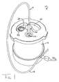
図1は、全体を10として表し、ハウジングに回転可能なように取り付けられたベース14およびカバー16を有するハウジング12を含む光学機器が示されている。光源がカバーに設置されたコネクター20で受けられる場合、光ファイバーシース18は、光ファイバーを保持する。ドロップヘッド組み付け品22(以下に説明される)が見えるが、これはカバー16に設けられた開口部24を通して利用できる。ファイバー光源は、いずれか他の適切な光源、例えば、カバーに組み込まれたLEDにより置換可能である。
DETAILED DESCRIPTION OF PREFERRED EMBODIMENTS FIG. 1 shows an optical instrument that includes a
一般的に、機器は、カバーが図1に示す投入位置にある場合には、開口部を介してドロップヘッド組み付け品22上に液体試料液滴を投入し、その後、カバー16を測定位置に回転し、それにより、コネクター20がドロップヘッド組み付け品22上に直接配置されることにより作動する。ドロップヘッド組み付け品22上の液体試料の液滴が、光ファイバーケーブル18により上部から照射される。検出器(見えない)は、ドロップヘッド組み付け品の透過性部分の下部に配置され、液体試料との光相互作用を集め、測定する。測定された光は、電子シグナルに変換され(任意選択で、機器10上で前処理してもよい)、得られたシグナルは、シグナルケーブル26を介して分析用に出力される。
In general, when the cover is in the loading position shown in FIG. 1, the instrument throws a liquid sample droplet onto the
カバーは、上面および下面から、それぞれ、図2と3にさらに詳細に示されている。カバー16は、扁平円柱または円板の一般的な形状をとる。中央の孔28は、スピンドル30(図1)を受けるように設けられ、ハウジング12に取り付けられると、そのスピンドルの周りで、カバーが回転する。いんげん豆形の一対の開口部24、32が、カバー16の外表面34(図1と2)および内表面36(図3)の間を通して伸びる。
The cover is shown in more detail in FIGS. 2 and 3, respectively, from the top and bottom surfaces. The
開口部24、32は、カバーが適切な角度の位置まで回転されると、中央孔28から半径方向にドロップヘッド組み付け品22(図1)の上に来るような寸法に空隙をあけて配置される。同様に、コネクター22は、中央孔28から半径方向に空隙をあけて配置され、それにより、カバーが適切な角度位置まで回転されると、それも同様にドロップヘッド組み付け品の上に重なることになる。カバー16の外周部40の周りの一組の3つの突起38が設けられ、回転によりカバーの操作を助ける。
The
コネクター22は、カバー外表面の陥凹部中に設定され、光ファイバー18(図2と3には示さず)がコネクター22に接続される場合、ファイバーの末端が内表面36と同一平面上にあることを確実にする。
The
開口部24、32および中央孔28に加えて、ファイバー末端が通過して出てくる受け孔42が内表面(図3)上に示されている。
In addition to the
また、内表面上に、一組の3つの等角度に間隔を空けて配置された陥凹部44、46、48(すなわち、相互に120°の角度で配置された)が示され、これらは、それぞれ、ハウジングに取り付けられたベアリングボールを受ける寸法になっている(下記でさらに説明される)。円周方向溝50も同様に示され、これも以下でさらに説明される。
Also shown on the inner surface is a set of three equiangularly spaced recesses 44, 46, 48 (ie, arranged at an angle of 120 ° to each other), which are Each is dimensioned to receive a bearing ball attached to the housing (further described below). A
さらに図4を参照すると、カバーを取り除いた場合、ハウジング12の頂面52が示されている。ドロップヘッド組み付け品22、および一組の3つのベアリングボール54、56、58が示され、これらのそれぞれは、ハウジングの頂面中に組み込まれ、それにより、カバーがベアリングボールの先端に沿ってスライドする。ベアリングボールは、また、等角度で配置され、カバーが測定位置にある場合、ベアリングボール54、56、58が次のように陥凹部44、46、48(図3)で受けられるような位置に置かれ:陥凹部44がベアリングボール54を受け;陥凹部46がベアリングボール56を受け;さらに、陥凹部48がベアリングボール58を受ける。
Still referring to FIG. 4, the
カバーが測定位置から1つの投入位置まで、反時計回りに120度回転される場合(これは、図1の位置である)、今度は、陥凹部44がベアリングボール56を受ける、等となる。反時計方向へのさらなる回転は、第1のピン60(図4)の、溝50(図3)の一方の末端に設けられた停止位置62との相互作用により防止される。
If the cover is rotated 120 degrees counterclockwise from the measurement position to one loading position (this is the position of FIG. 1), then the recess 44 receives the bearing ball 56, and so on. Further rotation in the counterclockwise direction is prevented by the interaction of the first pin 60 (FIG. 4) with a
次に、カバーが時計方向に120°回転される場合は、再度測定位置になり、さらに時計方向に120°の回転により、第2のピン64が溝50のもう一方の末端にある停止位置66に到達し、陥凹部44がベアリングボール58を受けることになる。
Next, when the cover is rotated clockwise by 120 °, the measurement position is reached again, and when the cover is further rotated by 120 ° clockwise, the
カバーが、中央測定位置および時計回りに120°または反時計回りに120°のどちらかの投入位置の間の中間位置にある場合、ベアリングボール54、56、58は、陥凹部44、46、48のいずれの位置にもないが、その代わりに、陥凹部44、46、48のそれぞれが存在する円周方向溝50中に正確に位置する仮想的円周方向軌道(図示せず)に沿って、カバーの内表面36(図3)を押しつける。
When the cover is in an intermediate position between the central measurement position and the insertion position of either 120 ° clockwise or 120 ° counterclockwise, the bearing
さらに図5を参照すると、スプリング70を保持し、ドーム形ヘッド72、スピンドルシャフト74およびねじ山末端部76を有するスピンドル部材68が示されている。
Still referring to FIG. 5, a
さらに図6を参照すると、スピンドル部材68の完成組み立て品、カバー16およびハウジング52の頂面が、ドロップヘッド組み付け品22、ベアリングボール54および図4のスピンドル部材68のねじ山部76を受ける中央ねじ穴78を通る線に沿った側面断面図中に示されている。
Still referring to FIG. 6, the complete assembly of the
図6では、カバー16が測定位置に回転されている。従って、陥凹部44で受けられているベアリングボール54(および、実際には、図では見えない他の2つのベアリングボール56、58が、それぞれ他の2つの陥凹部46、48に受けられている)のために、カバー16の内表面36およびハウジングの頂面52が近接しているのがわかる。カバーは、カバー16をドーム72から離れるようにさせるスプリング70により、ハウジングと接触するように下方に偏らされる。図6は、内表面36および頂面52が接触しているように示しているが、実際には、コネクター20およびドロップヘッド組み付け品22周辺のシール接触があるのを除いて、そのほとんどの面積全体でわずかに空隙がある。これについては、図11に関連して、下記でさらに説明される。
In FIG. 6, the
図からわかるように、測定位置では、光ファイバー18は、ドロップヘッド組み付け品22の上部に直接に配置される。3つの陥凹部に密接に適合する一組の3つのベアリングボールの使用により、カバーが測定位置に近づくと、液滴支持面上に保持された液滴上に直接配置される光ファイバーの位置へのカバーの非常に正確な押し込み式の嵌合が生じる。これに関しては以下でさらに詳細に示される。カバーを下方に偏らせるスプリングは、カバーの偶発的移動に対しこの位置を保持し、この位置から離れる動きに対し小さな抵抗を与え、それにより、カバーが1つまたは他の測定位置へ回転を開始する際に、操作者が明確にカバーを回転させ、ベアリングボール表面の頂点を越えて持ち上げる必要が生じる。
As can be seen, in the measurement position, the
示されたカバーが投入位置にあり、ピペット79により、いんげん豆形の投入用開口部24の1つを通して、ドロップヘッド組み付け品22の台座100上に液滴98を沈着させることを除いて、図7は、図6に類似の図である。
7 except that the cover shown is in the loading position and the
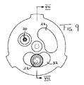
図8、9および10は、カバーが3つの異なる位置にある装置の上面図を示す:図8は、第1の投入位置にある(図1と同じ)カバーを示し;図10は、図8から時計回りに120°回転された測定位置にあるカバーを示し;さらに、図9は、時計回りにさらに120°回転された第2の投入位置にあるカバーを示す。 8, 9 and 10 show a top view of the device with the cover in three different positions: FIG. 8 shows the cover in the first loading position (same as FIG. 1); FIG. FIG. 9 shows the cover in the measuring position rotated 120 ° clockwise; and FIG. 9 shows the cover in the second loading position rotated further 120 ° clockwise.
図11は、カバーおよびハウジングの詳細拡大図を示し、特に、光源およびコネクターの詳細、すなわち、光ファイバーシース18、外部光源(図示せず)からの光を保持する末端表面82で終わる実際のファイバー80およびシース18をカバー16にはめ合わせるコネクター20の一部を示す。
FIG. 11 shows a detailed close-up view of the cover and housing, in particular the actual fiber 80 ending in the details of the light source and connector, ie the
カバー16の内表面36は、一段高い管状縁84を持ち、その上にOリングシール86が取り付けられ、ファイバーの末端表面82が管状縁84内の中央に収容される。従って、陥凹部によりカバーが適所に下がり、ベアリングボールが位置合わせ状態にあることにより、また、前に説明のようにスプリングの下方に押す作用により、Oリング86が、ハウジングの頂面52でシールを形成する。
The
さらに、図11からのドロップヘッド組み付け品単体22の図12を参照すると、全体を22で表したドロップヘッド組み付け品の詳細が、ここで説明される。組み付け品22は、一段高い外縁90および一段高い内表面92(外縁よりも低い)を有するプラスチック環状外側本体88を含む。外縁90および内表面92の間には、環状周縁凹部またはリザーバー94がある。これは、使用中は、液体(試験する液体、すなわち、液滴が好ましい)または試験に用いる液体の主要成分、例えば、試験に用いる液体に使われる溶媒または懸濁用液体で、部分的にまたは完全に満たされる。試験に使う液体が複合組成物の場合は、その液体の主要成分の1つをリザーバー中に置くことができる(例えば、ワインまたはビールを試験する場合、環状周縁凹部を、水で満たしてもよく;マニキュア液を試験する場合、環状周縁凹部を、アセトンで満たしてもよい)。
Further, referring to FIG. 12 of the
環状周縁凹部中の液体の目的は、試験する液体周辺に、さらに一般的には、内表面36、頂面52およびシール86で規定されるチャンバー96内に、より高い飽和度の雰囲気を生成することである。測定位置に回転される場合、カバー16が適所に下がるとすぐに、このチャンバー96は、シールされ、また、チャンバー96が小容量であるので、蒸気平衡は、すぐに達成され、その後、液滴の蒸発は、大きく抑制される。
The purpose of the liquid in the annular peripheral recess is to create a higher saturation atmosphere around the liquid to be tested, and more generally in the
シールされたチャンバーは、また、安全な廃棄を可能とするためにシール容器中に送り込み、試料をパージするのに使用できる。このようなシールされた試料用チャンバーを使って、湿度または実際に他の環境因子、例えば、ガスまたは蒸気の混合物、生物学的分子等を死滅させる殺菌用UVのための、例えば、温度、大気の種類の制御を行うことができる。 The sealed chamber can also be used to pump into a sealed container and purge the sample to allow safe disposal. Such a sealed sample chamber can be used for humidity or indeed other environmental factors such as gas or vapor mixtures, biomolecules etc. for germicidal UV, eg temperature, atmosphere Types of control can be performed.
液滴98は、それ単独で、黒水晶円板102に取り付けられた円柱状石英台座100の先端に規定される液滴支持面上に乗る。黒水晶は、石英と融合してドロップヘッドに原子的に結合した構造であるように使用されるが、試料ヘッドとは光学的に識別され、液滴と検出器(図示せず)の間の台座を通る光ガイド効果を助けるものである。ファイバー80からの液滴98に照射された光は、石英台座100を通して、台座100の直下、またはその台座の直下のファイバー(図示せず)中に置かれた検出器(図示せず)にカップリングされる。
The
容量が十分小さく、重力より表面張力が優位である液滴に対し、液滴の光学特性は、液滴の形状および液体自体の組成の両方に依存する。同じ容量の2つの液滴に対し、表面張力は、形状もまた同じであることを保証する。従って、正確に同じ容量の2つの液滴の光学特性を比較でき、また、何らかの差異は、それぞれの液体の光学特性、例えば、カップリング効率、屈折率、濁度、色、清澄性、減衰、蛍光、等によることになる。それらの組成が異なる場合、2つの幾何学的に同じ液滴は、固有の光学的に明確な特徴を持ち、従って、2つの液滴を適切な光で照射し、透過光を検出器で測定することにより、有用な分析を行うことができる。 For droplets that are sufficiently small in volume and superior in surface tension over gravity, the droplet optical properties depend on both the droplet shape and the composition of the liquid itself. For two drops of the same volume, the surface tension ensures that the shape is also the same. Thus, the optical properties of two droplets of exactly the same volume can be compared, and any differences can be attributed to the optical properties of each liquid, such as coupling efficiency, refractive index, turbidity, color, clarity, attenuation, This is due to fluorescence, etc. If their composition is different, the two geometrically identical droplets have unique optically distinct characteristics, so that the two droplets are illuminated with appropriate light and the transmitted light is measured with a detector By doing so, a useful analysis can be performed.
しかし、今まで説明した技術は、測定値が採取される時間に液滴の形状が同じであることに依存する。必要な正確さの程度の同じ小さい容積の液体を沈着させるために、通常の注意深い研究室技術および装置を使用することは確かに可能であるが、また、これにより、必然的に、同じ形状および大きさの液滴が得られるが(極めて異なる表面張力特性を有するいずれかの大きく異なる液体は別にして)、液滴中の液体が、台座上のその沈着を行う場所および測定を行う場所の間で蒸発が起こる場合は、不正確さが発生する可能性がある。実際に、中断および他の因子が、沈着と測定の間の時間を遅らせ、1つの測定から別の測定を広範囲にわたり変動させる原因となり、また、蒸発を防ぐための予防措置がない場合は、大きな不正確さを持ち込むこととなる可能性がある。 However, the techniques described so far rely on the droplet shape being the same at the time the measurement is taken. While it is certainly possible to use normal careful laboratory techniques and equipment to deposit the same small volume of liquid with the required degree of accuracy, this also necessarily results in the same shape and Droplets of a size are obtained (apart from any very different liquid with very different surface tension properties), but the liquid in the droplet is where the deposition takes place on the pedestal and where the measurement takes place. Inaccuracies may occur if evaporation occurs between them. In fact, interruptions and other factors can delay the time between deposition and measurement, causing a wide variation from one measurement to another, and can be significant if there are no precautions to prevent evaporation Inaccuracy may be introduced.
周縁凹部94およびチャンバー96のシールにより、これらの不正確さを除くことができ、または少なくとも不正確さを小さいものにする。チャンバー96がシールされるとすぐに、蒸気平衡が、急速に達成され、その後、液滴の蒸発が大きく抑制される。従って、測定値または一連の測定値採取の長時間の遅れは、問題とならない。理由は、液滴容量は、チャンバー中の空気の容量を飽和する周縁凹部内の相対的に大きな容量の液体から生ずる蒸気圧力に起因して、蒸発に対抗して安定化されるためである。
These inaccuracies can be eliminated or at least made inaccurate by sealing the
図13は、光学的測定システム110を示す。これは、台112上に取り付けられた図1〜12の装置10を含み、またその台は、それに取り付けられた、光ファイバーシース18が接続されている光源114を有する。光源114は、任意の所望の特性を有する光(本明細書で使われるこの用語は、可視光線、赤外線、紫外線およびさらにマイクロ波照射を包含する)を提供するようにカスタマイズできる。出力シグナルケーブル26は、どの分析装置にも接続されるように示されていないが、実際には、これは、適切な分析ソフトウェアを実行しているコンピュータに接続し、出力シグナルから試験液滴の必要な光学特性を測定できる。また、台112上には、ピペットチップ118用の容器116を設置でき、それにより、操作者が容易に手の届く範囲の位置に、これらを保管できる。
FIG. 13 shows an optical measurement system 110. This includes the apparatus 10 of FIGS. 1-12 mounted on a
図14は、全体を120として表す完全に組み上げた機器を示す。これは、ハウジング122を含み、その上に取り付けられ、光ファイバーシース18を受けるカバー16(前に説明のように)を有する。機器120は、ハウジング122内に、オンボード光源、検出器、および操作者によりタッチスクリーン124で提供される入力に基づいて光源および検出器を制御するためのプログラム可能な電子機器を含む。プログラム可能な電子機器は、光源および検出器とインターフェイスをとるために適切にプログラムされた汎用コンピュータにより構成され、それにより、操作者は、光源からの光のファイバーでの発生、検出器の操作特性および前に説明のように台座を通って出てくる検出光に基づいてデータ収集を制御できる。コンピュータは、出力シグナルを特徴付け、比較するための適切な分析ソフトウェアでプログラムできる。
FIG. 14 shows a fully assembled device, denoted as 120 in its entirety. This includes a housing 122 and has a cover 16 (as previously described) mounted thereon and receiving a
図15は、上面図によるさらなる機器を示す。機器は、主に2つの点で図1とは異なる。 FIG. 15 shows a further device according to a top view. The device differs from FIG. 1 in two main ways.
第1に、一対のドロップヘッド組み付け品22A、22Bは、ハウジングの頂面52上に配置され、また、開口部24、32は、ドロップヘッド組み付け品22A、22Bの両方が同時に現れるのを可能とするような形状と大きさである。これにより、操作者が両ドロップヘッドに一度に投入することが可能となる。
First, a pair of
図1の実施形態と同様に、2つの開口部の提供により、カバーを測定位置からどちらか一方向へ回転させ、投入を可能とさせる。 Similar to the embodiment of FIG. 1, the provision of two openings allows the cover to be rotated in either direction from the measurement position to allow insertion.
第2に、ベアリングボールおよび陥凹部の位置決め機構は、図15の実施形態で修正され、2つの安定な投入位置を与え、この場合、コネクター20が1つまたは他のドロップヘッド組み付け品22A、22Bと位置合わせされた状態にされる。従って、第1の投入位置では、カバーが下がり(陥凹部に位置するベアリングボールにより)、シールが形成されて、チャンバーを規定し(図11の場合のように)、ファイバーが第1のドロップヘッド組み付け品22A上の台座の液滴支持面の上部に配置される。第2の投入位置では、カバーは同様に下がり(陥凹部にあるベアリングボールにより)、シールが形成されて、チャンバーを規定し(図11の場合のように)、ファイバーが、第2のドロップヘッド組み付け品22B上の台座の液滴支持面の上部に配置される。カバーが内表面上にさらなる対の図11のシール86と同じ環状シールを備え、それにより、シール86がドロップヘッド22A、22Bの内の1つの周りに配置される場合に、残りのドロップヘッドもまた、カバーの下のシールされた雰囲気中にあることが好ましい。このように、測定されていないドロップヘッドが、測定中でないにもかかわらず、液滴の周りの飽和雰囲気でシールされた状態にあり、蒸発を防ぐ。
Second, the bearing ball and recess positioning mechanism is modified in the embodiment of FIG. 15 to provide two stable loading positions, in which case the
図15の装置は、従って、ただ1回の投入操作の一部として、同じドロップヘッド22A、22B上で2つの試料が次々に投入されるのを可能とし、また、さらなる試料またはドロップヘッドとの何ら干渉なしに、これら2つの試料の測定が次々と行われるのを可能とする。このように、対照および未知試料が一緒に投入され、同じ条件下でほぼ同時に、ドロップヘッドが2つの試料の間で汚染される可能性が全くない状態で試験でき、それにより、正確さが高められ、誤りの可能性が低減されて、信頼性の高い、繰り返し可能な比較が可能となる。
The apparatus of FIG. 15 thus allows two samples to be loaded one after the other on the
図16および17は、図1の機器に対する修正を示す(この修正は、また、他の実施形態のいずれに対しても行うことができる)。図16は、以下に説明する修正を除いて、図1のものに同じであるハウジング12を含む全体システムを示す。図17は、図11に類似の図である。
16 and 17 show a modification to the device of FIG. 1 (this modification can also be made for any of the other embodiments). FIG. 16 shows the overall system including a
図17では、環状シール86の内側にハウジングの頂面52を貫通する一対の導管126、128があり、従って、チャンバー96内のシールされた空気量につながるのがわかる。導管126は、パージガス、例えば、窒素またはヘリウムの加圧ボンベ130(図17)に接続された入口導管である。導管128は、大気または例えば、通風室、等の排気システム132に接続された出口導管である。典型的な例では、入口および出口導管の両方が、ハウジング12の外部コネクター134、136につながり、それに対し、加圧ボンベ130および排気システム132(必要に応じ)が接続される。最終的には、タイマー138に接続されたソレノイドにより作動された単純なシンプルバルブ142が、スイッチ140の操作者の動作によるボンベの操作を自動化するために装備される。
In FIG. 17, it can be seen that there is a pair of
図16のシステムの操作は、以下の通りである。試料の測定後、および投入位置に戻すように回転する前に(試料が有害な場合)、スイッチ140が作動され、136を開き、加圧ガス130をチャンバー96内に入れる。典型的なガス圧力は、1.5barであってもよい。入口導管126から出口導管128の方に急送された加圧ガスは、ドロップヘッド上の液滴を吹き飛ばし、それにより、試料がチャンバー96から吸い出される。所定の時間後、ソレノイドは動作を停止し、バルブを閉じ、その後、カバーは、投入位置に回転し、全く液滴のない台座を露出させることができる。典型的な例では、操作者は、ドロップヘッドをティッシュペーパーで拭き、全ての残渣を除去し、次の試料の準備ができた状態になる。当業者なら、回転の全ステップ、ソレノイド動作、等が自動的に行えるように、このシステムを様々な所望の程度に自動化することができることに気付くであろう。
The operation of the system of FIG. 16 is as follows. After measurement of the sample and before rotating back to the loading position (if the sample is detrimental), switch 140 is activated, 136 is opened, and pressurized gas 130 is placed into
図18は、上述のいずれかの機器で使用するための制御および操作システムのブロックダイアグラムである。制御システムは、全ての許容されたパラメータの範囲内でそれぞれ、光源と検出器を操作できるハードウェア光源コントローラ202およびハードウェア検出器コントローラ204を有するインターフェイス200を介して、機器が機能できるように結びつける。 FIG. 18 is a block diagram of a control and operation system for use with any of the devices described above. The control system ties up the instrument to function via an interface 200 having a hardware light source controller 202 and a hardware detector controller 204 that can operate the light source and detector, respectively, within all allowed parameters. .
命令は、オペレーターインターフェース208、ワーキングメモリ210ならびにディスク記憶装置212を有するプロセッサ206からインターフェイス200に送られる。プロセッサ、オペレーターインターフェース、ワーキングメモリおよびディスク記憶装置は、適切にプログラムされた汎用コンピュータの一部として提供されてもよく、または、構成要素の相互作用を制御する適切なオペレーティングシステムを有する専用ハードウェア部品として提供されてもよいことは理解されよう。 The instructions are sent to the interface 200 from a processor 206 having an operator interface 208, a working memory 210 and a disk storage device 212. The processor, operator interface, working memory and disk storage may be provided as part of a suitably programmed general purpose computer or a dedicated hardware component with a suitable operating system that controls the interaction of the components It will be appreciated that may be provided as:
プログラム命令214は、ディスク212に保存され、ディスク212は、また、種々のデータ要素、例えば、較正データ216および結果および報告218を保存する。ソフトウェア214が作動中の場合に、インターフェイス208を介して操作者に提示されるスクリーンおよび制御装置の観点から、プログラム命令214下のシステムの操作について、以下で説明される。
Program instructions 214 are stored on disk 212, which also stores various data elements, such as
図19の導入スクリーンは、次のタブを含む:システム、メインテナンス、適用および統計。システムタブは、図19に示す下記のメニューオプションを有する: The introductory screen of FIG. 19 includes the following tabs: system, maintenance, application and statistics. The System tab has the following menu options shown in FIG. 19:
1.基本的セットアップおよびチェック
最初のメニューオプションは、機器、等が正しく接続されているかを確認する単純なテキスト命令である。これは、最も基本的なセットアップ命令である。
1. Basic Setup and Check The first menu option is a simple text instruction that confirms that the device, etc. is connected correctly. This is the most basic setup instruction.
2.光源チェック
光源の調節は、いくつかの基本的注意が必要なもので、さらに、ユーザーにいくつかの診断試験が与えられ、光源が使えるようになっていることを確認する(例えば、光源を確かめることは、スイッチを入れ、ファイバーを取り出し、光が光源からきていることをチェックすること、等である)。
2. Light source check Adjusting the light source requires some basic caution and, in addition, confirms that the user is given some diagnostic tests and that the light source is ready to use (eg, verify the light source (Turn on the switch, remove the fiber, check that light is coming from the light source, etc.).
3.分光計チェック
分光計の調節は、使われる分光計の型に依存し、ソフトウェア上でのいくつかの設定(例えば、積分時間の設定、等)に注意が必要である。
3. Adjustment of the spectrometer check spectrometer depends on the type of spectrometer used, and some settings in the software (eg, integration time settings, etc.) require attention.
4.システムチェック
ここで、光源、滴下装置および分光計の最良の操作を確実にする(例えば、光源制御装置の調節および分光計を最適化し、シグナルが飽和しないことを確実にする)ために行うことができるいくつかの単純なシステムチェックがある。ソフトウェアは、ユーザーにシステムのパフォーマンスを最適化するように指示することができる。このオプションの選択により、次に、システムの調節に関するユーザー指示を与える。
4). System check here to do to ensure the best operation of the light source, dripping device and spectrometer (for example, adjusting the light source controller and optimizing the spectrometer to ensure that the signal does not saturate) There are a few simple system checks that can be done. The software can instruct the user to optimize system performance. Selection of this option then gives user instructions regarding the adjustment of the system.
5.較正
較正基準が提供され、システムが、最適化された後でこれらが実行される場合は、波長チェックおよび感度、線形性および再現性チェックが実行できる。測定値が記録された後で、サービスの基本報告は、サービスアーカイブに保存され、この報告は印刷できる。
5. If calibration calibration standards are provided and these are performed after the system has been optimized, wavelength and sensitivity, linearity and reproducibility checks can be performed. After the measurements are recorded, the basic report for the service is saved in the service archive and this report can be printed.
液滴機器が「空」の場合に、参照材料からスペクトルを取り、コンピュータのメモリに保存する。このデータセットは、分光計により帰属された波長に対する光強度の配列である。次に、液滴試料を通して透過した光源光の強度が、全波長に対し保存される。その後、
補正試料および参照強度(強度−各波長に対する暗電流)を使って、アルゴリズム:

Using the corrected sample and reference intensity (intensity-dark current for each wavelength), the algorithm:
スペクトルに関しては:
スペクトルスクリーンをjpg画像に保存するオプションがある。
スペクトルの目盛りを変化させ、例えば、DNAのみの場合、200〜400nmの波長範囲が必要である。
同じスクリーンディスプレイ上に2つ以上のスペクトルを表示できる場合、スペクトルオーバーレイコントロールを可能とし(後日)、ソフトウェアは、前に記録したスペクトルの読み込みを可能とする。スペクトルは、異なる色で示される。
オートレンジは、これが選択される場合は、スクリーンディスプレイ上の目盛りを自動的に設定する。
選択された全設定は、ファイルのヘッダーに保存される。
波長値は、可能な場合には、該当するチェックボックスの左側で上下矢印を使って選択するか、または数値を入力することによりさらに直接的に選択できる。
For the spectrum:
There is an option to save the spectral screen to a jpg image.
For example, in the case of DNA alone, a wavelength range of 200 to 400 nm is required by changing the spectrum scale.
If more than one spectrum can be displayed on the same screen display, spectral overlay control is enabled (at a later date) and the software allows reading of previously recorded spectra. The spectra are shown in different colors.
Autoranging automatically sets the scale on the screen display when this is selected.
All selected settings are saved in the file header.
Wavelength values can be selected using the up and down arrows to the left of the appropriate check box, if possible, or more directly by entering a numerical value.
液滴分光計の較正は、市販の標準Starna Green Calibration Fluidを使って行う。所与の測定濃度に対する既知の吸光度の既知のスペクトル特性およびピークを有する他の製品を使ってもよい。2つまたは3つの波長での吸光度値が、標準の測定により得られ、既知の値と比較される。反復読み取りが行われ、平均され、標準偏差が得られる。標準と既知値との比較により、機器の光度測定の正確さの較正が行われ、標準偏差が光度測定再現性の尺度となる。結果の分析が、下表に示すようなスプレッドシートで自動的に返される。
繰り返し数は選択できるが、10が最小で、32を越える回数が試験の統計的妥当性の改善に基づいて推奨される。 The number of repetitions can be selected, but 10 is the minimum and a number of more than 32 is recommended based on improving the statistical validity of the test.
液滴機器の較正試験は、2%より高い正確さとすべきであり、診断では、較正がうまくいかない場合は、ソフトウェアで反復較正により測定値を改善することが推奨される。 Droplet instrument calibration tests should be more than 2% accurate and diagnostics recommend that if calibration is unsuccessful, the software should improve the measurement by iterative calibration.
試験の報告は、ユーザーのPC上に自動的に作られる較正報告ファイルに自動的にファイルされる。この報告書は、スクリーンのハードコピーとして、またはファイルから印刷できる。 The test report is automatically filed in a calibration report file that is automatically generated on the user's PC. This report can be printed as a hard copy of the screen or from a file.
6.機器の自動最適化
このオプションは、較正結果に基づいて機器のパラメータの自動最適化を可能とする。
図19のメインタブに戻ると、「メインテナンス」タブを選ぶと、下記のオプションが示される:
1.ルーチンサービス(インサイツドロップヘッドクリーニング):クリーニングキットを使ってルーチンサービスを行い、液滴機器が、例えば、タンパク質汚染により影響されない良質の測定値を出すことを確実にする簡単なステップがある。
2.ドロップヘッド交換:ドロップヘッド交換のためのツールが提供され、既存のドロップヘッドの取り外しと交換の説明が示される。
3.ドロップヘッド(機器からの取り外したもの):溶媒浴中に浸漬された機器から取り出されたドロップヘッドの清掃方法の説明がなされる。
4.検出器の交換:次のオプションでは、検出器交換に関する説明が行われる(ここでは、機器キットの一部ではない簡単なツールの使用が必要となる)。
5.ファイバーのソラリゼーションのチェック:最終チェックでは、機器の運転、および較正標準を使ったスペクトル測定が必要となる。波長範囲200〜260nmでのノイズの受容可能なレベルに関するガイダンスが与えられる。
6). Automatic instrument optimization This option allows automatic optimization of instrument parameters based on calibration results.
Returning to the main tab of FIG. 19, selecting the “Maintenance” tab gives you the following options:
1. Routine service (in situ drop head cleaning): There is a simple step to perform a routine service using a cleaning kit to ensure that the droplet instrument produces a good quality measurement that is unaffected by, for example, protein contamination.
2. Drophead replacement: Tools for drophead replacement are provided and instructions for removing and replacing existing dropheads are provided.
3. Drophead (removed from the instrument): Describes how to clean the drophead removed from the instrument immersed in the solvent bath.
4). Detector replacement: The next option provides instructions for detector replacement (which requires the use of a simple tool that is not part of the instrument kit).
5. Fiber solarization check: The final check requires instrument operation and spectral measurements using calibration standards. Guidance is given regarding acceptable levels of noise in the wavelength range 200-260 nm.
「適用」タブは、ユーザーが、(S)単滴、または(D)複滴操作、を選択する必要がある。操作は、後者のオプションが2つの液滴(試料と参照材料)の沈着を使うことを除いて、ほとんど同じである。アルゴリズムは、これらの試験に対する一般に容認された計算方法に適合し、アッセイ用の一般に容認された統計的分析にも適合する結果を得るためのデータ取得の後に、実行されるものである。 The “Apply” tab requires the user to select (S) single drop or (D) double drop operation. The operation is almost the same except that the latter option uses the deposition of two droplets (sample and reference material). The algorithm is to be executed after data acquisition to obtain a result that is compatible with generally accepted calculation methods for these tests and that is also compatible with generally accepted statistical analysis for assays.
例として、単液滴操作を採用すると、ユーザーには、下記のオプションが与えられる: As an example, adopting single drop operation gives the user the following options:
1.較正グラフを使った直接測定
化学および生物学における標準的測定手法は、いくつかの選択波長の測定に対し、いくつかの他の溶媒の水溶液中の溶解成分の測定のために、濃度に対する吸光度の較正グラフを作成することである。次に、このBeer−Lambert較正グラフを使って、未知の溶液の濃度を決定する(測定濃度はこの較正グラフから線図を使って決定される)。
1. Standard measurement techniques in direct measurement chemistry and biology using calibration graphs are used to measure absorbance versus concentration for the measurement of dissolved components in aqueous solutions of several other solvents, for the measurement of some selected wavelengths. Creating a calibration graph. The Beer-Lambert calibration graph is then used to determine the concentration of the unknown solution (the measured concentration is determined from the calibration graph using a diagram).
一例を図20に示す。ここでは、測定量は吸光度で、測定尺度は濃度である。図20は、典型的な較正を示し、グラフから測定するために重要な点は:
(i)較正感度(m−グラフの傾斜)
(ii)分析感度(k=m/σblank;σblank:ブランクの反復測定から通常得られる測定量値の標準偏差)
(iii)検出限界(LOD):測定量尺度から較正線に対し投影し、3σblankに対する測定尺度に下ろした切片の値。
(iv)定量限界(LOQ):10σblankに対する切片を使うことを除いて、同様に決定できる。
(v)直線性限界:フィッティング多項式の線形プロットからの3σblankを越える値の変化により決定される。
An example is shown in FIG. Here, the measurement amount is absorbance, and the measurement scale is concentration. FIG. 20 shows a typical calibration, and the important points to measure from the graph are:
(I) Calibration sensitivity (m-slope of graph)
(Ii) Analytical sensitivity (k = m / σ blank ; σ blank : standard deviation of measurement value normally obtained from repeated measurement of blank)
(Iii) Limit of detection (LOD): The value of the intercept projected from the measurand scale to the calibration line and down to the measurable scale for 3σ blank .
(Iv) Limit of quantification (LOQ): can be determined in the same way except using the intercept for 10σ blank .
(V) Linearity limit: determined by a change in value exceeding 3σ blank from a linear plot of the fitting polynomial.
ソフトウェアは、ソフトウェア熟練者に問い合わせをしないで、データを自動的に記録し、結果を自動的に下表に入力する機会をユーザーに与える。また、測定試料は、反復測定が必要であり、最新エラー分析手法により、濃度と濃度誤差の両方の値が返される。測定が進行するにつれ、結果の統計的許容性に関するチェックがすぐに行われ(下表参照)、統計的に許容可能なこれらのセットに関する測定後、ユーザーに較正測定を反復させるように提供されるオプションと共に、チェックマークが現れる。結果が統計的に許容可能である場合、チェックマークがボックス中に現れる。さらに、較正測定値が許容可能でない理由に関する提案が行われるが、これらは、統計的に妥当な結果を得ながら進めるよりも、反復を促されているユーザーには必要がない。
結果のスクリーンも提示でき、これは、ユーザーに、LOQおよびLOLの間の濃度の測定値を得ることを知らせる。図20のデータは、大凡のデータ分析のためのいくつかのアイデアを提供する。ここでは、値は、m=0.0126
A−unit.L/mgである。ここで、10σblank=0.0756である(式LOQ=6mg/Lから計算)。LODは、1.9mg/Lである。グラフは直鎖で、非直線性の徴候はなく、従って、LOLとして100mg/Lを採用する。この調査用に特別に開発されたエラー分析手法を使って、ソフトウェアは、これらの値を返す。
A screen of results can also be presented, which informs the user to obtain a concentration measurement between LOQ and LOL. The data in FIG. 20 provides some ideas for general data analysis. Here, the value is m = 0.126.
A-unit. L / mg. Here, 10σ blank = 0.0756 (calculated from the formula LOQ = 6 mg / L). The LOD is 1.9 mg / L. The graph is linear with no signs of non-linearity, therefore, 100 mg / L is adopted as the LOL. The software returns these values using an error analysis technique developed specifically for this investigation.
このグラフから、エラーバンド用の式が、3σエラーバーに対して、この範囲の値でA軸上の切片の値を置き換えた2本の直線を使って、計算される。示されたグラフでは、範囲は、3σblank=0.0125である。従って、エラーバンド用の式は、2本の直線:Atop=0.0126c+0.0027([0.0125−0.0098]から計算)および下側の直線Abottom=0.0126c−0.0223([−0.0125−0.0098]から計算)である。これにより、濃度測定は、容易に行える。 From this graph, the error band equation is calculated for the 3σ error bar using two straight lines obtained by replacing the intercept value on the A axis with a value in this range. In the graph shown, the range is 3σ blank = 0.0125. Thus, the error band equation is two straight lines: A top = 0.0126c + 0.0027 (calculated from [0.0125−0.0098]) and the lower straight line A bottom = 0.0126c−0.0223. (Calculated from [−0.0125−0.0098]). Thereby, the concentration measurement can be easily performed.
未知試料の測定吸光度は、Aunknown=0.464±0.015(3σ値を誤差として採用)で、AT=0.479〜AL=0.449の値の吸光度範囲を示す。未知試料の濃度の計算には、graph viz上で得られる最適合線の式:cunknown=(0.446/0.0126)+0.0098=35.41mg/L、を使用する。濃度誤差は、AtopおよびAbottom用の2つの式を使って、未知試料の濃度測定値の吸光度範囲から計算される。式中のAbottomをAT=0.479で置き換えて38を得て、式中のAtopをAL=0.449で置き換えて35.66を得ることにより濃度範囲が計算される。 The measured absorbance of the unknown sample is A unknown = 0.464 ± 0.015 (3σ value is adopted as an error), and shows an absorbance range of A T = 0.479 to A L = 0.449. For the calculation of the concentration of the unknown sample, the formula of the best fitting line obtained on graph viz: c unknown = (0.446 / 0.0126) + 0.0098 = 35.41 mg / L is used. The concentration error is calculated from the absorbance range of the concentration measurement of an unknown sample using two equations for A top and A bottom . The concentration range is calculated by replacing A bottom in the equation with A T = 0.479 to obtain 38 and substituting A top in the equation with A L = 0.449 to obtain 35.66.
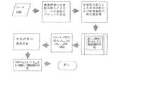
これにより、結果35.41±2.59(c±Δc)が得られる。実際には、このアルゴリズムの例では、ここで示された誤差は、グラフ上のエラーバーがわかるようにするために誇張されており、これらは、大きさが2倍になっている。そのため、これらの本当の液滴分析器セットで得られた実際の本当の測定結果は、35.41±1.295mg/Lである。アルゴリズムは、図21のフローダイアグラムにより説明できる。 As a result, the result 35.41 ± 2.59 (c ± Δc) is obtained. In fact, in this example algorithm, the errors shown here are exaggerated to make the error bars on the graph visible, and they are doubled in size. Therefore, the actual real measurement result obtained with these real drop analyzer sets is 35.41 ± 1.295 mg / L. The algorithm can be described by the flow diagram of FIG.
2.RNA/DNA
(i)アルゴリズムは、数値的相関関係に変換された、確立した実験的相関関係に基づいている。定数は、単鎖および二重鎖DNAならびにRNAの間で異なる。これらは、1本鎖DNA、DSDNA、RNAで表され、実際には、他の核酸もある。核酸タイプを選択する。
(ii)3つの波長260、280および320nmの「液滴分光計」吸光度の測定値が記録される。
(iii)DNAの純度を評価するための式:
(I) The algorithm is based on established experimental correlations that have been converted to numerical correlations. Constants differ between single and double stranded DNA and RNA. These are represented by single-stranded DNA, DSDNA, and RNA, and actually there are other nucleic acids. Select the nucleic acid type.
(Ii) “Droplet Spectrometer” absorbance measurements at three wavelengths 260, 280 and 320 nm are recorded.
(Iii) Formula for evaluating the purity of DNA:
純粋なDNAは1.8、およびRNAは2.0の値となる。低い値は、タンパク質の存在、または変性DNAの存在を示す。2つ目の有用な純度比率の尺度:純度推定値2=A260/A230 がある。これらの比は、DNA濃度(ng/nL):CDNA=(A260−A320)*50*PF(PF=液滴分析器に対する経路長因子)が吸光度測定値に基づくことを除いて、有用である。例えば、3nL液滴に対して、経路長は、モデル化調査および実験的試験から得られた1.184mmである。2mm直径ドロップヘッドを使った実験的調査では、PF=−0.0054VD 2+0.2872VD+0.3549の式が得られた。式中、VDは、液滴容量(マイクロリットル)である。その値を標準の10mm経路長吸収測定の値に変換するための経路長の計算は、単純にPF/10である。液滴分光計ソフトウェアで報告された全ての値は、標準的分光光度計および10mmキュベットを使って得られた値に対応するものである。 Pure DNA has a value of 1.8, and RNA has a value of 2.0. A low value indicates the presence of protein or the presence of denatured DNA. There is a second useful measure of purity ratio: purity estimate 2 = A 260 / A 230 . These ratios are based on DNA concentration (ng / nL): C DNA = (A 260 -A 320 ) * 50 * PF (PF = path length factor for drop analyzer) based on absorbance measurements, Useful. For example, for a 3 nL droplet, the path length is 1.184 mm obtained from modeling studies and experimental tests. In an experimental investigation using a 2 mm diameter drop head, the formula PF = −0.0054 V D 2 +0.2872 V D +0.3549 was obtained. In the formula, V D is a droplet volume (microliter). The path length calculation to convert that value to the standard 10 mm path length absorption measurement value is simply PF / 10. All values reported in the droplet spectrometer software correspond to those obtained using a standard spectrophotometer and a 10 mm cuvette.
(iv)タンパク質アッセイ
これらの測定値に基づくタンパク質スクリーンは、選択方法に依存し、例えば、280nmでの測定は、図22に示すスクリーンとなる。
UV−可視スペクトルの表示が下記と一緒に示される:
1cm経路長に基づく280nmでの吸光度の測定。
表示濃度に対する消衰係数の入力値。
濃度測定値
![]()
A display of the UV-visible spectrum is shown along with:
Absorbance measurement at 280 nm based on 1 cm path length.
Input value of extinction coefficient for display density.
Concentration measurement
![]()
(v)BCAアッセイ
BCAアッセイでは、タンパク質(未知)を測定する前に、実行時毎回生成される検量線が必要となる。
測定は、562nmのλMaxで行われ、750nmで分析される。
(V) BCA assay The BCA assay requires a calibration curve generated each time it is run before measuring the protein (unknown).
Measurements are taken at 562 Max at 562 nm and analyzed at 750 nm.
吸光度値は、タンパク質濃度に比例する。
ユーザーは、随時検量線を見直すことが可能。
検量線を生成する際の注意は次記の通り:(i)参照材料を測定する(BCA試薬および「ゼロに設定した」標準)(ii)ソフトウェア制御は、統計的検査がデータに対し実行できるのを保証するために、2回未満の反復数による測定を許容しない(iii)ユーザーは、5回の反復を行うことが推奨される(iv)アッセイ中のステップで、大きな説明ボックスが、交通信号システムの赤/緑でユーザーを案内し、測定のための検量線の準備がいつ出来ているかを示す(v)アッセイ工程でヒントをユーザーに与えるためHELPを利用できる。
Absorbance values are proportional to protein concentration.
The user can review the calibration curve at any time.
Notes on generating a calibration curve are as follows: (i) Measure reference material (BCA reagent and “set to zero” standard) (ii) Software control allows statistical tests to be performed on the data (Iii) Users are encouraged to perform 5 iterations (iv) In the steps in the assay, a large description box will HELP can be used to guide the user through the red / green signal system and indicate when the calibration curve is ready for measurement (v) hints to the user during the assay process.
図23は、BCAアッセイの結果を示す。較正に関連して、ユーザーは、図23に示す表をクリックし、試料を削除し、その後、測定セットを再度反復できる。その後、更新された測定セットが、直ちにグラフ上に示される。 FIG. 23 shows the results of the BCA assay. In connection with calibration, the user can click on the table shown in FIG. 23, delete the sample, and then repeat the measurement set again. The updated measurement set is then immediately displayed on the graph.
その検量線が完成するとすぐに、赤の標識光が緑に変わり、「go」を示すこの条件でのみ、ユーザーが測定を開始できる。 As soon as the calibration curve is complete, the red marker light turns green and the user can start the measurement only under this condition indicating “go”.
緑の光の点灯に伴い、較正グラフが消え、スペクトルスクリーンと入れ替わる。
切替オプション:ユーザーが較正グラフまたはスペクトルを調べて検量線を見直すことができるようにする。
較正オプション:以前に保存した較正か、または新しい較正の作成かをユーザーが選択できるようにする。
柔軟な計算オプション:標準的1cmの経路長に基づいた吸光度の計算(下式)と一緒に、選択経路長(容量)に基づく560nmおよび750nmでのマイクロドロップ吸光度が表示される。
Switching option: Allows the user to review the calibration curve by examining the calibration graph or spectrum.
Calibration option: Allow the user to choose between a previously saved calibration or creating a new calibration.
Flexible calculation options: Microdrop absorbance at 560 nm and 750 nm based on selected path length (volume) is displayed along with calculation of absorbance based on standard 1 cm path length (below).
注記:濃度値(ng/mL)を得るためには、未知試料は、検量線の許容限界内に入る必要があり、濃度測定値は、試料間の直線フィッティングにより得られる。検量線の傾斜m(較正感度)および較正グラフの切片(c)は、最小二乗フィットを使ってソフトウェアにより決定される。
(d)次に、濃度が下式により得られる:
(D) The concentration is then obtained by the following formula:
(vi)ローリーアッセイ
タンパク質試料(未知濃度)の測定の前に、必要な検量線が実行毎に生成される。試料は、750nmで測定され、450nmで正規化される。この場合のスクリーンは、ローリー法のボックスが選択されていることを除いた、上記BCAの場合に示されるものである。
(Vi) Raleigh assay The required calibration curve is generated for each run prior to measurement of protein samples (unknown concentrations). Samples are measured at 750 nm and normalized at 450 nm. The screen in this case is shown in the case of the BCA except that the Raleigh method box is selected.
(vii)ブラッドフォードアッセイ
タンパク質試料(未知濃度)の測定の前に、必要な検量線が実行毎に生成される。試料は、2つの波長:595nmおよび750nm(正規化用)で測定される。この場合のスクリーンは、ブラッドフォード法のボックスが選択されていることを除いた、上記BCAの場合に示されるものである。
(Vii) Bradford assay Before the measurement of protein samples (unknown concentrations), the required calibration curve is generated for each run. The sample is measured at two wavelengths: 595 nm and 750 nm (for normalization). The screen in this case is that shown in the case of the BCA except that the Bradford box is selected.
(viii)ビウレットアッセイ
タンパク質試料(未知濃度)の測定の前に、必要な検量線が実行毎に生成される。試料は、2つの波長で測定される。測定は546nmで行われる。この場合のスクリーンは、ビウレット法のボックスが選択されていることを除いた、上記BCAの場合に示されるものである。
(Viii) Biuret assay Before the measurement of the protein sample (unknown concentration), the required calibration curve is generated for each run. The sample is measured at two wavelengths. Measurements are made at 546 nm. The screen in this case is shown in the case of the BCA except that the biuret method box is selected.
(ii)複滴
1.直接測定
2.DNA/RNA
3.タンパク質アッセイ(i)ローリー(ii)ブラッドフォード(iii)ビウレット
(Ii) Double drops Direct measurement DNA / RNA
3. Protein Assay (i) Raleigh (ii) Bradford (iii) Biuret
測定手続きは、HELPの記載が複滴沈着のための説明に変わったことを除いて、上記と同様である。 The measurement procedure is the same as above except that the HELP description has been changed to an explanation for double droplet deposition.
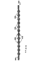
図24〜27は、マイクロプレートリーダーで使用するためのマイクロプレート型のドロップヘッド代替形式を示す(平面図(図24)、側面図(図25)、側面断面図(図26:図24の線A−Aに沿って切り出したもの)および底面図(図27))。示した寸法(mm)は、代表例に過ぎない。 FIGS. 24-27 show an alternative form of a microplate-type drop head for use in a microplate reader (top view (FIG. 24), side view (FIG. 25), side cross-sectional view (FIG. 26: line of FIG. 24) (Taken along AA) and bottom view (FIG. 27)). The dimensions (mm) shown are merely representative.
一括して図24〜26を参照すると、ドロップヘッド300は、一段高い外縁302を有し、その内側に、リザーバー304、その内側に整列して配置された96個の一段高い孤立台座306を含む。
Referring collectively to FIGS. 24-26, the
孤立台座上には、一段高い円柱状台座308があり、その上面には、それぞれ液滴支持面を備える。 On the isolated pedestal, there is a cylindrical pedestal 308 that is one step higher, and each has an upper surface provided with a droplet support surface.
ドロップヘッド22上の単一環状リザーバーの場合と同様な方式で、リザーバー304が水または別の溶媒、等の液体で満たされ、手作業で、またはそれぞれの液滴が従来のロボット沈着システムを使って各液滴支持面308上に沈着され、孤立台座が液滴支持面からリザーバーを分離する。リザーバー304内の液体は、ドロップヘッド300上に高められた蒸気圧をもたらし、操作中および読み取り中の液滴の蒸発を防ぐ。各液滴を通して光を照射し、それにより液滴中の試験液体がその光と相互作用し、分析のためにプレートの下部の検出器または検出器配列が各液滴を通過した光を検出することにより、従来のマイクロプレートリーダー(図示せず)を使ってドロップヘッドを測定できる。
In a manner similar to that of a single annular reservoir on the
図26および27からわかるように、一連の96個の凸レンズ310が、ドロップヘッド300の底面312の各孤立台座と液滴支持面の下に一体品として備えられている。レンズ310は、液滴および台座から検出器に通過する光に焦点を当てている。別のレンズ構造も使用可能であり、またはそれらを完全に省いて、検出器が、単純にドロップヘッドの平らな裏面を通過する光を集めてもよい。
As can be seen from FIGS. 26 and 27, a series of 96
本発明は、請求発明の範囲を逸脱することなく修正可能な本明細書記載の実施形態に限定されない。 The invention is not limited to the embodiments described herein which can be modified without departing from the scope of the claimed invention.
Claims (32)
液滴を受けるための液滴支持面を有するハウジングと、
外表面および内表面を有するカバーであって、前記ハウジングに取り付けられ、それにより、前記内表面が前記ハウジングの液滴支持面に面するカバーと、
光源を受け、前記光源および前記カバーの内表面の間で通信を行わせるための前記カバー上に設けられたコネクターと、
前記カバーに設けられ、その中を通って伸びる投入用開口部であって、前記コネクターから間隙を置いて配置されている投入用開口部と、
前記カバーおよび前記ハウジングの間で、測定および投入位置の間の軸の周りの相対的回転運動を可能とする前記カバーおよび前記ハウジングの間に設けられた据え付け台であって、前記測定位置では、前記コネクターが前記液滴支持面を基準として配置され、それにより、前記コネクターで受けられた光源が前記液滴支持面を照射するように配置され、また、前記投入位置では、前記投入用開口部が前記液滴支持表面に接近出来るように配置される、据え付け台と、
前記測定位置に到達した場合に前記カバーを係合し、それにより前記光源および液滴支持面が間隙を置いて固定された位置関係に維持されることを確実にするために前記カバーおよび前記ハウジングの間で設けられた位置決め機構と
を含む、光学機器。 An optical instrument,
A housing having a droplet support surface for receiving droplets;
A cover having an outer surface and an inner surface, wherein the cover is attached to the housing such that the inner surface faces a droplet support surface of the housing;
A connector provided on the cover for receiving a light source and causing communication between the light source and the inner surface of the cover;
A closing opening provided in the cover and extending therethrough, the opening being disposed with a gap from the connector;
A mounting base provided between the cover and the housing that allows a relative rotational movement about an axis between the cover and the housing between a measuring and a loading position, The connector is arranged with respect to the droplet support surface, whereby a light source received by the connector is arranged to irradiate the droplet support surface, and at the loading position, the loading opening A mounting base arranged to be accessible to the droplet support surface;
The cover and the housing to engage the cover when the measurement position is reached, thereby ensuring that the light source and droplet support surface are maintained in a fixed and spaced relationship And a positioning mechanism provided between the optical devices.
前記カバーを測定位置に回転するステップであって、前記測定位置では、前記カバーの内表面上に照射をもたらす光源が前記液滴支持面を照射するように配置され、また、前記測定位置では、前記光源および液滴支持面が空隙を置いて固定された関係に維持されるステップと
を含む液滴の光学特性の測定方法。 Depositing the droplets on the droplet support surface through a loading opening of a device cover rotatably mounted on the device housing, wherein the loading opening when the cover is in a loading position Allowing the portion to access the droplet support surface;
Rotating the cover to a measurement position, wherein at the measurement position, a light source providing illumination on the inner surface of the cover is arranged to irradiate the droplet support surface, and at the measurement position, And maintaining the light source and the droplet support surface in a fixed relationship with an air gap therebetween.
Applications Claiming Priority (3)
| Application Number | Priority Date | Filing Date | Title |
|---|---|---|---|
| EP11162343.5 | 2011-04-13 | ||
| EP11162343 | 2011-04-13 | ||
| PCT/EP2012/056835 WO2012140232A2 (en) | 2011-04-13 | 2012-04-13 | Optical instruments |
Publications (1)
| Publication Number | Publication Date |
|---|---|
| JP2014510930A true JP2014510930A (en) | 2014-05-01 |
Family
ID=46001187
Family Applications (1)
| Application Number | Title | Priority Date | Filing Date |
|---|---|---|---|
| JP2014504351A Pending JP2014510930A (en) | 2011-04-13 | 2012-04-13 | Optical equipment |
Country Status (4)
| Country | Link |
|---|---|
| US (1) | US9086353B2 (en) |
| EP (1) | EP2697624B1 (en) |
| JP (1) | JP2014510930A (en) |
| WO (1) | WO2012140232A2 (en) |
Families Citing this family (4)
| Publication number | Priority date | Publication date | Assignee | Title |
|---|---|---|---|---|
| US9274044B2 (en) * | 2012-11-28 | 2016-03-01 | Wyatt Technology Corporation | Cuvette for light scattering measurements incorporating evaporation inhibition means |
| GB2531293A (en) | 2014-10-14 | 2016-04-20 | Stephen Smith | Determining an absorption coefficient of a liquid |
| WO2019063745A1 (en) * | 2017-09-27 | 2019-04-04 | Advanced Nano Technologies Limited | Apparatus for analysing the optical properties of a sample |
| GB2590369A (en) * | 2019-12-10 | 2021-06-30 | Stratec Se | Positioning of diagnostic consumables |
Citations (7)
| Publication number | Priority date | Publication date | Assignee | Title |
|---|---|---|---|---|
| JPS60140143A (en) * | 1983-12-08 | 1985-07-25 | ヘキスト・アクチエンゲゼルシヤフト | Head section of photometer for slight measuring volume |
| JPS63132169A (en) * | 1986-11-21 | 1988-06-04 | Hitachi Ltd | Automatic analyzer with rotary cover |
| JPH02156143A (en) * | 1988-12-07 | 1990-06-15 | Fuji Photo Film Co Ltd | Apparatus for holding liquid to be inspected |
| JPH02194351A (en) * | 1989-01-24 | 1990-07-31 | Suzuki Motor Co Ltd | Detector for deterioration of oil |
| JPH11326308A (en) * | 1998-05-14 | 1999-11-26 | Serim Res Corp | Instrument and method for incubation test of test piece |
| JP2006345813A (en) * | 2005-06-17 | 2006-12-28 | Toppan Printing Co Ltd | Reaction vessel and method for reaction |
| JP2007333440A (en) * | 2006-06-13 | 2007-12-27 | Furukawa Electric Co Ltd:The | Sample measuring method, and sample measuring device |
Family Cites Families (8)
| Publication number | Priority date | Publication date | Assignee | Title |
|---|---|---|---|---|
| DE3005148A1 (en) * | 1980-02-12 | 1981-08-20 | Hartmann & Braun Ag, 6000 Frankfurt | Photometric gas analyser test appts. - uses measurement and reference cuvettes with rotating disc cuvette selector |
| JPS5815157A (en) * | 1981-07-22 | 1983-01-28 | Fuji Photo Film Co Ltd | Incubating method |
| DE69940647D1 (en) * | 1998-05-01 | 2009-05-07 | Gen Probe Inc | Automatic diagnostic analyzer |
| EP2333561A3 (en) * | 2005-03-10 | 2014-06-11 | Gen-Probe Incorporated | System for performing multi-formatted assays |
| JP4645739B2 (en) * | 2006-04-03 | 2011-03-09 | 株式会社島津製作所 | Optical measuring device for trace liquid samples |
| WO2007131945A2 (en) | 2006-05-12 | 2007-11-22 | Carl Stuart Limited | Microvolume analysis system |
| EP2071317B1 (en) * | 2006-10-06 | 2020-05-20 | Shimadzu Corporation | Spectrophotometer |
| JP2008275364A (en) * | 2007-04-26 | 2008-11-13 | Toyota Motor Corp | Fluid permeation state evaluation device |
-
2012
- 2012-04-13 EP EP12717077.7A patent/EP2697624B1/en active Active
- 2012-04-13 US US14/111,306 patent/US9086353B2/en active Active
- 2012-04-13 JP JP2014504351A patent/JP2014510930A/en active Pending
- 2012-04-13 WO PCT/EP2012/056835 patent/WO2012140232A2/en active Application Filing
Patent Citations (7)
| Publication number | Priority date | Publication date | Assignee | Title |
|---|---|---|---|---|
| JPS60140143A (en) * | 1983-12-08 | 1985-07-25 | ヘキスト・アクチエンゲゼルシヤフト | Head section of photometer for slight measuring volume |
| JPS63132169A (en) * | 1986-11-21 | 1988-06-04 | Hitachi Ltd | Automatic analyzer with rotary cover |
| JPH02156143A (en) * | 1988-12-07 | 1990-06-15 | Fuji Photo Film Co Ltd | Apparatus for holding liquid to be inspected |
| JPH02194351A (en) * | 1989-01-24 | 1990-07-31 | Suzuki Motor Co Ltd | Detector for deterioration of oil |
| JPH11326308A (en) * | 1998-05-14 | 1999-11-26 | Serim Res Corp | Instrument and method for incubation test of test piece |
| JP2006345813A (en) * | 2005-06-17 | 2006-12-28 | Toppan Printing Co Ltd | Reaction vessel and method for reaction |
| JP2007333440A (en) * | 2006-06-13 | 2007-12-27 | Furukawa Electric Co Ltd:The | Sample measuring method, and sample measuring device |
Also Published As
| Publication number | Publication date |
|---|---|
| EP2697624B1 (en) | 2017-05-31 |
| US20140085628A1 (en) | 2014-03-27 |
| WO2012140232A3 (en) | 2012-12-13 |
| EP2697624A2 (en) | 2014-02-19 |
| US9086353B2 (en) | 2015-07-21 |
| WO2012140232A2 (en) | 2012-10-18 |
Similar Documents
| Publication | Publication Date | Title |
|---|---|---|
| US7576855B2 (en) | Spectrophotometric method and apparatus | |
| JP5539367B2 (en) | Dual sample mode spectrophotometer | |
| US20070229830A1 (en) | Sample analyzer and sample analyzing method | |
| WO1997019340A1 (en) | Apparatus and method for rapid spectrophotometric pre-test screen of specimen for a blood analyzer | |
| US6522398B2 (en) | Apparatus for measuring hematocrit | |
| JP6023805B2 (en) | Optical spectrometer with underfill optical fiber sample interface | |
| CN211877738U (en) | Spectrophotometric assay and liquid handling system | |
| Jones et al. | Basics of assay equipment and instrumentation for high throughput screening | |
| JP2014510930A (en) | Optical equipment | |
| JP3121603B2 (en) | Automatic chemical analyzer for multiple samples and reagents | |
| EP3344978B1 (en) | Apparatus and method for performing a light-absorption measurement on a test sample and a compliance measurement on a reference sample | |
| US8115922B2 (en) | Apparatus and method for adapting conventional cuvettes for use in a vertical light beam spectrophotometer | |
| US5638171A (en) | Spectrophotometer with self-contained module | |
| JP7206570B2 (en) | Analysis equipment | |
| DE10149879B4 (en) | Device for the spectrophotometric analysis of liquid media | |
| JP2007187445A (en) | Autoanalyzer | |
| WO1999047261A1 (en) | Method and apparatus for measuring proteins | |
| JP2007170984A (en) | Sample cell and spectrophotometer using the same | |
| CN201166662Y (en) | Full-automatic biochemical analysizer with outlay type reaction disk signal sampling apparatus | |
| CN208383707U (en) | A kind of automatic ultraviolet-uisible spectrophotometer | |
| US20020110487A1 (en) | Apparatus and method for handling fluids | |
| EP2255172A1 (en) | Apparatus and method for adapting conventional cuvettes for use in a vertical light beam spectrophotometer | |
| US20180024045A1 (en) | Pipette Tip, Pipette, Apparatus and Kit for Light Measurement | |
| WO2023282075A1 (en) | Automatic analysis device and reaction vessel | |
| CN115718094A (en) | Sample analysis device and sample analysis method |
Legal Events
| Date | Code | Title | Description |
|---|---|---|---|
| A621 | Written request for application examination |
Free format text: JAPANESE INTERMEDIATE CODE: A621 Effective date: 20150413 |
|
| A977 | Report on retrieval |
Free format text: JAPANESE INTERMEDIATE CODE: A971007 Effective date: 20160224 |
|
| A131 | Notification of reasons for refusal |
Free format text: JAPANESE INTERMEDIATE CODE: A131 Effective date: 20160308 |
|
| A601 | Written request for extension of time |
Free format text: JAPANESE INTERMEDIATE CODE: A601 Effective date: 20160607 |
|
| A02 | Decision of refusal |
Free format text: JAPANESE INTERMEDIATE CODE: A02 Effective date: 20161115 |