JP2014510287A - Container optical inspection method and apparatus - Google Patents
Container optical inspection method and apparatus Download PDFInfo
- Publication number
- JP2014510287A JP2014510287A JP2014502799A JP2014502799A JP2014510287A JP 2014510287 A JP2014510287 A JP 2014510287A JP 2014502799 A JP2014502799 A JP 2014502799A JP 2014502799 A JP2014502799 A JP 2014502799A JP 2014510287 A JP2014510287 A JP 2014510287A
- Authority
- JP
- Japan
- Prior art keywords
- container
- light source
- mouth
- punt
- light
- Prior art date
- Legal status (The legal status is an assumption and is not a legal conclusion. Google has not performed a legal analysis and makes no representation as to the accuracy of the status listed.)
- Pending
Links
Images


Classifications
-
- B—PERFORMING OPERATIONS; TRANSPORTING
- B07—SEPARATING SOLIDS FROM SOLIDS; SORTING
- B07C—POSTAL SORTING; SORTING INDIVIDUAL ARTICLES, OR BULK MATERIAL FIT TO BE SORTED PIECE-MEAL, e.g. BY PICKING
- B07C5/00—Sorting according to a characteristic or feature of the articles or material being sorted, e.g. by control effected by devices which detect or measure such characteristic or feature; Sorting by manually actuated devices, e.g. switches
- B07C5/34—Sorting according to other particular properties
- B07C5/3404—Sorting according to other particular properties according to properties of containers or receptacles, e.g. rigidity, leaks, fill-level
- B07C5/3408—Sorting according to other particular properties according to properties of containers or receptacles, e.g. rigidity, leaks, fill-level for bottles, jars or other glassware
-
- G—PHYSICS
- G01—MEASURING; TESTING
- G01N—INVESTIGATING OR ANALYSING MATERIALS BY DETERMINING THEIR CHEMICAL OR PHYSICAL PROPERTIES
- G01N21/00—Investigating or analysing materials by the use of optical means, i.e. using sub-millimetre waves, infrared, visible or ultraviolet light
- G01N21/84—Systems specially adapted for particular applications
- G01N21/88—Investigating the presence of flaws or contamination
- G01N21/90—Investigating the presence of flaws or contamination in a container or its contents
- G01N21/9072—Investigating the presence of flaws or contamination in a container or its contents with illumination or detection from inside the container
Abstract
容器口部(M)と、該容器口部とは反対側のパント(P)をもった底部(B)とを有する容器(C)を検査するための装置及び方法。少なくとも1つの光源(12a又は12b又は12c)を使用して、光エネルギを容器内に向けて容器口部を通るようにし、該容器口部を通って伝達された光エネルギを感知する。少なくとも1つの光源が、該容器の少なくとも1つの側に配置され、光エネルギが、容器の側壁(W)を通り、容器底部のパントに向けられ、該光エネルギの少なくとも一部が該パントにより反射されて、容器口部を通り光センサに向けて進行するようになる。
【選択図】 図1An apparatus and method for inspecting a container (C) having a container mouth (M) and a bottom (B) having a punt (P) opposite to the container mouth. At least one light source (12a or 12b or 12c) is used to direct light energy into the container through the container mouth and sense light energy transmitted through the container mouth. At least one light source is disposed on at least one side of the container, and light energy is directed through the container side wall (W) to a punt at the bottom of the container, and at least a portion of the light energy is reflected by the punt. Then, it proceeds toward the optical sensor through the container opening.
[Selection] Figure 1
Description
本発明は、容器の光学的検査の方法及び装置に関する。 The present invention relates to a method and apparatus for optical inspection of containers.
容器の製造にあたっては、容器の商業上の許容性に影響する様々な不規則性及び変形が生じることがある。これらの不規則性は、「商品の変形」と呼ばれ、容器の多くの属性を含むものである。例えば、商品の変形は、容器の開口した口部の寸法特性に関連することがある。従って、商品の変形について、容器の検査を行うことができる検査機器を提供することは、多くの場合、有用である。「検査」という用語は、全ての光学的、電子光学的、機械的又は電気的な観察、或いは、容器に触れて、商品の変形を含むが必ずしもそれに限定するものではない、変動の可能性がある特性を測定し又は求めることを含む、最も広い意味で使用される。 During the manufacture of a container, various irregularities and deformations can occur that affect the commercial acceptability of the container. These irregularities are called “deformation of goods” and include many attributes of the container. For example, merchandise deformation may be related to the dimensional characteristics of the open mouth of the container. Therefore, it is often useful to provide an inspection device that can inspect a container for deformation of a product. The term “inspection” is subject to all optical, electro-optical, mechanical or electrical observations, or the possibility of variation, including but not necessarily limited to deformation of the product by touching the container. Used in the broadest sense, including measuring or determining a characteristic.
容器口部のパラメータを検査するための装置は、容器の検査方法の一形態において使用される。そのような装置は、容器に光エネルギを向ける光源と、容器の口部を通って容器の外に伝達される光エネルギを受信するように、該光源及び容器に対して配置された光センサとを含む。テレセントリック・レンズは、容器口部のほぼ軸線方向に該容器口部を通して伝達された光エネルギのみを光センサに向けるようにする。このセンサは、容器の口部の二次元画像を生成し、容器の口部の二次元画像に適合する最大直径の円を求めるか又は計算し、その円を容器口部の有効内径の指針として処理する画像処理電子回路に連結されている。このような形態の装置は、本出願の譲受人に譲渡された特許文献1に示されており、この特許文献1は、引用により本明細書に組み入れられる。 An apparatus for inspecting a parameter of a container mouth is used in one form of a container inspection method. Such a device includes a light source that directs light energy at the container, and a light sensor disposed relative to the light source and the container to receive light energy transmitted through the mouth of the container and out of the container. including. The telecentric lens directs only the light energy transmitted through the container mouth in the substantially axial direction of the container mouth to the optical sensor. This sensor generates a two-dimensional image of the container mouth, determines or calculates the maximum diameter circle that fits the two-dimensional image of the container mouth, and uses that circle as a guide for the effective inner diameter of the container mouth. Linked to image processing electronics for processing. An apparatus of this type is shown in US Pat. No. 6,057,028, assigned to the assignee of the present application, which is hereby incorporated by reference.
本開示の一側面による、本開示の一般的な目的は、底部にパントを有する容器における容器口部の検査を改善するのに有効な、光学的プラグゲージ(OPG)装置を提供することである。 According to one aspect of the present disclosure, a general object of the present disclosure is to provide an optical plug gauge (OPG) device that is effective in improving inspection of a container mouth in a container having a punt at the bottom. .
本開示は、多くの形態を実現するものであり、これらの形態は、互いに個別に、或いは組み合わせて実施可能である。 The present disclosure realizes many forms, and these forms can be implemented individually or in combination with each other.
容器口部と、該容器口部とは反対側の、パントをもった底部とを有する容器を検査するための、本開示の一側面による装置は、光エネルギを容器内に向け、該容器の口部を通って容器から出るように指向させるための少なくとも1つの光源と、該容器の口部を通って容器の外に伝達される光エネルギを受信するように、少なくとも1つの光源及び容器に対して配置された光センサとを含む。該少なくとも1つの光源が、容器の少なくとも1つの側に配置されており、光エネルギは、容器の側壁を通り、容器底部のパント上に向けられ、光エネルギの少なくとも一部が該パントにより反射されて、容器口部を通って光センサに向けて進行するようになる。 An apparatus according to one aspect of the present disclosure for inspecting a container having a container mouth and a bottom with a punt opposite the container mouth directs light energy into the container, At least one light source for directing out of the container through the mouth and at least one light source and container for receiving light energy transmitted out of the container through the mouth of the container And an optical sensor disposed against the optical sensor. The at least one light source is disposed on at least one side of the container, and light energy is directed through the container side wall onto the container bottom punt, and at least a portion of the light energy is reflected by the punt. Then, it proceeds toward the optical sensor through the container opening.
本開示の異なる側面によれば、容器口部と、該容器口部とは反対側の、パントをもった底部とを有する容器を検査する方法が提供され、該方法は、少なくとも1つの光源を使用して、光エネルギを容器内に向け、光エネルギが該容器の口部を通って容器から出るようにする段階と、該容器の口部を通って伝達された光エネルギを感知する段階とを含む。該少なくとも1つの光源は、容器の少なくとも1つの側に配置されており、光エネルギは、容器の側壁を通り、該容器の底部のパント上に向けられ、光エネルギの少なくとも一部が該パントにより反射されて、容器の口部を通り光センサに向けて進行するようになる。 According to a different aspect of the present disclosure, there is provided a method of inspecting a container having a container mouth and a bottom with a punt opposite the container mouth, the method comprising at least one light source. Using to direct light energy into the container, allowing the light energy to exit the container through the mouth of the container, and sensing light energy transmitted through the mouth of the container; including. The at least one light source is disposed on at least one side of the container, and light energy is directed through a side wall of the container and onto a punt at the bottom of the container, and at least a portion of the light energy is caused by the punt. Reflected and travels toward the optical sensor through the mouth of the container.
本開示の更に別の側面によれば、容器口部と、該容器口部とは反対側の、パントをもった底部とを有する容器を準備する段階と、少なくとも1つの光源を使用して、光エネルギを容器内に向け、光エネルギが該容器の口部を通って容器から出るようにする段階とを含む検査方法が提供される。該方法は又、少なくとも1つの光源が、容器の少なくとも1つの側に配置され、光エネルギが、容器の側壁を通り、該容器の底部のパント上に向けられ、光エネルギの少なくとも一部が該パントにより反射されて、容器の口部を通って光センサに向けて進行する過程において、容器口部を通って伝達される光エネルギを検出する段階を含む。 According to yet another aspect of the present disclosure, providing a container having a container mouth and a bottom with a punt opposite the container mouth, and using at least one light source, Directing light energy into the container and allowing the light energy to exit the container through the mouth of the container. The method also includes at least one light source disposed on at least one side of the container, and light energy is directed through a side wall of the container and onto a punt at the bottom of the container, at least a portion of the light energy being Detecting light energy transmitted through the container mouth in the process of being reflected by the punt and traveling toward the optical sensor through the mouth of the container.
本開示は、追加的な目的、形状、利点及び形態と共に、以下の説明、添付の請求項及び付随する図面によって、最も良く理解されるであろう。 The present disclosure, together with additional objects, shapes, advantages and forms, will best be understood by the following description, appended claims and accompanying drawings.
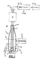
図1は、容器Cの開口部Mの内面Sを検査するための、光学的プラグゲージ装置10の典型的な実施形態を示している。本装置10は、容器Cの側方において該容器に隣接して配置され、容器口部Mの検査に使用される光を生成する、1又は2以上の光源12と、該光源12によって生成され、該容器口部Mを通る光を感知するために該容器Cの上方に配置された、1又は2以上の光センサ14とを含む。本装置10は更に、容器Cと光センサ14との間に配置されて、容器口部Mを通る光を、光センサ14に向けるためのレンズ装置18を含むことができる。装置10は、追加的に、光センサ14を走査し、容器口部M及び/又は他の全ての検査情報の画像を形成するためのプロセッサー20と、画像及び/又はその他の検査情報を表示するためのディスプレイ22とを含むことができる。装置10は又、容器Cを回転させるための容器回転器24を含むことができる。図3に示されるように、容器Cを動かすための材料取扱機構16を構築し、配置することができる。
FIG. 1 shows an exemplary embodiment of an optical
容器Cは、広口瓶、又は図1に示されているような瓶、或いは容器の口部Mとは軸方向に反対側に配置することができるパントPを有する底部Bを含む、他の何れかの適切な形式の容器でも良い。パントPを有する瓶は、ワインを入れるものとして一般的である。パントPは、底部Bの底面からパントPの頂点までの高さを有し、その高さは一般的に容器Cの外径の約20%から約80%までである。容器Cは、プラスチック、ガラス、又は他の何れかの適切な材料で構成されていても良い。容器Cは、濁りなし、色付き、透明、他のどのような適切な光学的性質のものでも良い。 Container C includes a wide-mouthed bottle, or a bottle as shown in FIG. 1, or any other, including a bottom B having a punt P that can be disposed axially opposite the mouth M of the container. Any suitable type of container may be used. Bottles with punts P are common for holding wine. The punt P has a height from the bottom surface of the bottom B to the apex of the punt P, and the height is generally about 20% to about 80% of the outer diameter of the container C. Container C may be constructed of plastic, glass, or any other suitable material. Container C may be non-turbid, colored, transparent, or any other suitable optical property.
図3に示されているように、材料取扱機構16は、対向する脚部16a,16bを含むことができ、該脚部16a,16bはその間に容器Cが配置され、機構16によって適切な何れかの方法で動かされる。機構16は、星形車又は他のどのような適切な容器取扱装置でも良く、その脚部16a,16bは、容器に対して適切な高さに配置されていれば良い。
As shown in FIG. 3, the
また、図3に示されているように、光源12は、複数の区分光源12a,12b,12cを含むことができる。例えば、光源12は、容器Cの一方の側の側面光源12aと、容器Cの他の側に、側面光源12aの側とほぼ反対の側に隣接して配置された他の二つの側面光源12b、12cと、を含むことができる。仮想線Lが、容器Cを2つの側に二分する。一方の側面光源12aは、材料取扱機構16の対向する脚部16a、16bの間に配置することができる。他方の側面光源12b、12cは、容器回転器24の下方で、容器回転器24と容器底部Bとの間の(図1)位置に配置することができる。このように、側面光源12a、12b、12cは、それぞれがパントPの周の一部、例えば約20度から40度の範囲を照らすように寸法が定められ、容器Cの周囲に配置される。その結果、容器Cは、その全周を照明できるようにするために、回転器24によって回転させることができ、これによって、容器口部Mの幾つかの部分の像が取得され、これらの像が重畳されるか、加えられることにより、容器口部Mの合成画像を構成することができる。当業者は、3つの側面光源12a、12b、12cよりも多く又はより少ない数の光源を使用してもよいことを認識するであろう。
As shown in FIG. 3, the
光源12は、複数の発光ダイオード(LED)、白熱電球、蛍光灯、又は他のあらゆる適切な形式の光源を含む、あらゆる適切な形式の装置を含むことができる。いずれにしても、当業者は、該光源12が、何れか適切な方法により、何れか適切な供給源から電力を受け、何れか適切な方法によりプロセッサー20と通信状態に置かれて、該プロセッサーにより制御されるようにすることができることを認識するであろう。更に、当業者は、光源12が、3つの光源12a,12b,12cのみから構成する代わりに、適当な数の個別光源によって構成してもよいことを認識するであろう。
The
図1を参照すると、好ましい形態では、光源12は、容器Cを二分する高さ半分のラインHより上にある容器Cの上半分に隣接しては配置されず、或いは、容器Cの底部Bより下方には配置されていない。光源12をそのように配置すると、容器Cの壁面による光の過剰吸収、及び/又は容器Cの内面からの屈折/反射を引き起こすことが見出された。そのような過剰吸収及び/又は屈折/反射は、検査の失敗又は不確定な結果、或いは信頼できない結果をもたらす可能性がある。
Referring to FIG. 1, in a preferred form, the
その代わりに、光源12は、容器Cの底部Bに隣接し、且つ高さ半分ラインHよりも下方の容器Cの下半分に隣接して配置してもよいことを見出した。より具体的には、光源12は、図1,2に示されているように、全体的に容器CのパントPに対応して設置することができる。例えば、光源12は、パントPに対して軸方向に中心が重なるように、及び/又は軸線方向に重なるようにすることができる。このように、光源12は、パントPを目標とするように、或いは選択的に照明するように構成され配置される。また、光源12は、図1,2に示されているように、容器Cの縦方向軸線Aに対してほぼ横方向に向けられるようにすることができる。より具体的には、光源12は、容器軸線Aに関してほぼ垂直に向けられるようにすることができる。ここで使用されている「ほぼ」という用語は、標準的なガラス容器製造及び装置の設定における公差の範囲内にあるという意味である。上述の光源位置及び/又は方向の1又は2以上のものが、過剰吸収及び/又は屈折/反射を減少又は除去し、より信頼性のある検査結果をもたらすと考えられる。
Instead, it has been found that the
図1を続けて参照すると、光センサ14は、光を感知するための適当な装置の何れかを含むことができる。例えば、光センサ14は、電荷結合デバイス(CCD)、相補的金属酸化物半導体(CMOS)デバイス、他の何れかの適当な画像センサのような、画像センサを含むことができる。他の例として、光センサ14は、光ダイオードデバイス、フォトレジストデバイス、又は他の何れかの光検出装置を含むものとすることができる。
With continued reference to FIG. 1, the
レンズ装置18は、光を方向づけ、又は合焦させるのに適したものであればどのような装置でも良い。例えば、レンズシステム18は、テレセントリック・レンズ、入射絞り、及び絞りの両側の絞りレンズを含むことができる。レンズ装置18は、容器口部Mから出る光線のみを容器Cの軸線Aに本質的に平行に指向させるものとすることができる。
The
プロセッサー20は、光センサ14からの画像を取得してディスプレイ22に出力するための、適切なデバイスを含むものであれば、どのようなものでも良い。
The
容器回転器24は、容器Cを回転させるための何れかの適切な装置を含んでいればよい。例えば、回転器24は、1又は2以上のローラー、車輪、ベルト、ディスク、及び/又は容器Cを回転させるための他の適切な要素を含んでいるものとすることができる。他の実施形態では、容器Cが静止状態に留まり、種々の装置要素12,14,16,18の1又は2以上のものが、何らかの適切な手法で回転させられるようにすることができる。
The
ここで図3を参照すると、材料取扱機構16及び容器回転器24については、本開示における光学的検査装置及び方法を利用することができる割付け及び検査機械の実施例が、特許文献2に記載されており、該特許文献2は、引用により本明細に組み入れられる。特許文献2に開示された機械は、送りこみコンベアからのガラス製品の連続流れを受け、角度方向に間隔を置いて配置された一連の検査ステーションを通して物品を移送し、該検査ステーションの各々は、異なる基準に従って容器を検査する。割付け及び検査機械は、下部キャリア上に取り付けられた把持用フィンガの第1の列と、上部キャリア上に取り付けられた把持用フィンガの第2の列とを含む。これらキャリアを互いに対して回転させることによって、フィンガの列が、個々のフィンガの間でガラス製品を把持及び解放するように作用し、一方、これらキャリアを同時に回転させることにより、これらキャリアが検査ステーション間にガラス製品を割付けするように作用する。検査ステーションの少なくとも幾つかは、検査又はその他の目的のために容器をその軸線周りに回転させるための駆動ローラーを含む。
Referring now to FIG. 3, for
本発明による光学的検査装置及び方法を利用できる割付け及び検査機械の異なる実施例が、引用により本明細書に組み入れられる特許文献3に開示されている。特許文献3に開示された装置は、容器を案内路に沿って移送するために、ベルトコンベアを使用している。一般的な作動時において、容器は割付けヘッドと相対するようになっており、該割付けヘッドは円形で、該容器を受けるための周方向に間隔を置いて配置された複数のポケットを有する。この割付けヘッドは、容器の各々を隣接する複数の検査ステーションの所定位置に順次に配置するように割付けを行い、これら検査ステーションは、様々な商品の変形及び/又は他の特性について容器を検査する。容器が各々の検査ステーションによって検査された後、該容器は送り出しステーションに到達し、該送り出しステーションは、容器を機械の外に運び出すために容器をコンベア上に送り出す。勿論、上述の特許文献は、光学的検査装置と本発明の方法を利用する機械の2つの実施例を開示するに過ぎないが、他に多くの機械もまた存在する。 A different embodiment of an assignment and inspection machine that can utilize the optical inspection apparatus and method according to the present invention is disclosed in US Pat. The apparatus disclosed in Patent Document 3 uses a belt conveyor to transfer the containers along the guide path. In general operation, the container is adapted to face the allocation head, the allocation head being circular and having a plurality of circumferentially spaced pockets for receiving the container. The allocation head assigns each of the containers to be sequentially placed at a predetermined location in adjacent inspection stations, which inspect the containers for various commodity deformations and / or other characteristics. . After the containers are inspected by each inspection station, the containers reach a delivery station that delivers the containers onto a conveyor to carry the containers out of the machine. Of course, the above-mentioned patent document only discloses two embodiments of an optical inspection device and a machine utilizing the method of the present invention, but many other machines also exist.
ここに開示された装置10の作動の一例において、光源12が励起され、側面光源12a、12b、12cからの光の少なくとも一部が、容器Cの外壁Wを通り抜けて容器Cの内部に入って、容器軸線Aに平行に延びるパントPにおいて反射され、容器口部Mを通り抜ける。より具体的には、光が、容器Cの内部I(図1)に配置されたパントPの表面において反射する。容器口部Mを通り抜ける光は、光センサ14によって感知され、容器口部Mの対応する画像が取得される。
In one example of the operation of the
以上、前述の目的及び意図を完全に満たす、容器の光学的検査のための装置及び方法が開示されている。本開示は、幾つかの典型的な実施形態に関連して示されており、追加的な修正及び変形が説明されている。前述した説明から、当業者は、その他の修正及び変形についての示唆を受けるであろう。 Thus, an apparatus and method for optical inspection of a container has been disclosed that fully satisfies the aforementioned objectives and intentions. The present disclosure has been presented in connection with some exemplary embodiments, and additional modifications and variations have been described. From the foregoing description, one of ordinary skill in the art will be aware of other modifications and variations.
10 光学的プラグゲージ装置
12 光源
14 光センサ
16 材料取扱機構
18 レンズ装置
20 プロセッサー
22 ディスプレイ
24 容器回転器
C 容器
M 容器口部
B 容器底部
W 容器の側壁
P パント
DESCRIPTION OF
Claims (20)
前記容器口部を通って伝達された光エネルギを受けるように前記少なくとも1つの光源及び前記容器に対して配置された光センサ(14)と、
を含む、容器口部(M)と、該容器口部とは反対側のパント(P)をもった底部(B)とを有する容器(C)を検査するための装置であって、
前記少なくとも1つの光源(12a、又は12b、又は12c)が、前記容器の少なくとも一方の側に配置され、前記光エネルギが前記容器の側壁(W)を通り、前記容器底部のパント(P)に向けられ、該光エネルギの少なくとも一部が前記パントにより反射されて、容器口部(M)を通って前記光センサ(14)に向けて進行するようになる
ことを特徴とする装置。 At least one light source (12a, or 12b, or 12c) for directing light energy into the container and exiting the container through the container mouth;
A light sensor (14) disposed relative to the at least one light source and the container to receive light energy transmitted through the container mouth;
An apparatus for inspecting a container (C) having a container mouth part (M) and a bottom part (B) having a punt (P) opposite to the container mouth part,
The at least one light source (12a, or 12b, or 12c) is disposed on at least one side of the container, and the light energy passes through the side wall (W) of the container to the punt (P) at the bottom of the container. Directed and at least a portion of the light energy is reflected by the punt and travels through the container mouth (M) towards the photosensor (14).
前記容器口部を通って伝達された光エネルギを感知する段階と、
を含む、容器口部(M)と該容器口部とは反対側のパント(P)をもった底部(B)とを有する容器(C)を検査するための方法であって、
前記少なくとも1つの光源が、容器の少なくとも1つの側に配置され、前記光エネルギが、前記容器の側壁を通り、前記容器底部のパントに向けられ、該光エネルギの少なくとも一部が前記パントにより反射されて、前記容器の口部を通って前記光センサに向けて進行するようになる
ことを特徴とする方法。 Directing light energy into the interior of the container using at least one light source and exiting the container through the container mouth;
Sensing light energy transmitted through the container mouth;
A method for inspecting a container (C) having a container mouth part (M) and a bottom part (B) having a punt (P) opposite to the container mouth part,
The at least one light source is disposed on at least one side of the container, the light energy is directed through a side wall of the container and directed to a punt at the bottom of the container, and at least a portion of the light energy is reflected by the punt. And proceeding towards the optical sensor through the mouth of the container.
少なくとも1つの光源を使用して光エネルギを容器内に向け、前記容器口部を通って容器から出てくるようにする段階と、
前記容器口部を通って伝達された光エネルギを感知する段階と、
を含む検査方法であって、
前記少なくとも1つの光源が、前記容器の少なくとも1つの側に配置され、前記光エネルギが、前記容器の側壁を通り、前記容器底部のパントに向けられ、該光エネルギの少なくとも一部が前記パントにより反射されて、前記容器の口部を通って前記光センサに向けて進行するようになる
ことを特徴とする方法。 Providing a container (C) having a container mouth (M) and a bottom (B) having a punt (P) opposite to the container mouth;
Directing light energy into the container using at least one light source and exiting the container through the container mouth;
Sensing light energy transmitted through the container mouth;
An inspection method including:
The at least one light source is disposed on at least one side of the container, the light energy is directed through a side wall of the container and directed to a punt at the bottom of the container, and at least a portion of the light energy is caused by the punt. A method of reflecting and traveling through the mouth of the container toward the photosensor.
Applications Claiming Priority (3)
| Application Number | Priority Date | Filing Date | Title |
|---|---|---|---|
| US13/074,789 US8896828B2 (en) | 2011-03-29 | 2011-03-29 | Optical inspection of containers |
| US13/074,789 | 2011-03-29 | ||
| PCT/US2012/031217 WO2012135503A1 (en) | 2011-03-29 | 2012-03-29 | Optical inspection of containers |
Publications (2)
| Publication Number | Publication Date |
|---|---|
| JP2014510287A true JP2014510287A (en) | 2014-04-24 |
| JP2014510287A5 JP2014510287A5 (en) | 2015-05-14 |
Family
ID=45955122
Family Applications (1)
| Application Number | Title | Priority Date | Filing Date |
|---|---|---|---|
| JP2014502799A Pending JP2014510287A (en) | 2011-03-29 | 2012-03-29 | Container optical inspection method and apparatus |
Country Status (14)
| Country | Link |
|---|---|
| US (1) | US8896828B2 (en) |
| EP (1) | EP2691762B1 (en) |
| JP (1) | JP2014510287A (en) |
| CN (1) | CN103703356B (en) |
| AR (1) | AR085570A1 (en) |
| AU (1) | AU2012236384C1 (en) |
| BR (1) | BR112013024492B1 (en) |
| CL (1) | CL2013002750A1 (en) |
| ES (1) | ES2805331T3 (en) |
| MX (1) | MX2013010956A (en) |
| PL (1) | PL2691762T3 (en) |
| TW (1) | TW201245702A (en) |
| WO (1) | WO2012135503A1 (en) |
| ZA (1) | ZA201305987B (en) |
Families Citing this family (4)
| Publication number | Priority date | Publication date | Assignee | Title |
|---|---|---|---|---|
| DE102015213352B4 (en) * | 2015-07-16 | 2018-10-31 | Krones Ag | Inspection device for a preform |
| RU2727082C2 (en) * | 2015-10-21 | 2020-07-17 | Тиама | Method and apparatus for providing optical inspection of vessels by their profile, including a bottom |
| CN106441022A (en) * | 2016-08-31 | 2017-02-22 | 山东省药用玻璃股份有限公司 | Full-servo bottleneck comprehensive inspection machine |
| FR3056296B1 (en) * | 2016-09-19 | 2018-10-19 | Tiama | INSTALLATION FOR THE OPTICAL INSPECTION OF GLASS CONTAINERS OUTPUT OF FORMING MACHINE |
Family Cites Families (13)
| Publication number | Priority date | Publication date | Assignee | Title |
|---|---|---|---|---|
| US3313409A (en) | 1964-02-07 | 1967-04-11 | Owens Illinois Inc | Apparatus for inspecting glassware |
| JPS5764153A (en) * | 1980-10-08 | 1982-04-19 | Mitsubishi Heavy Ind Ltd | Bottle inspecting device |
| JPS5768389A (en) | 1980-10-15 | 1982-04-26 | Hajime Sangyo | Inspecting device |
| US4580045A (en) * | 1982-08-06 | 1986-04-01 | Emhart Industries, Inc. | Apparatus for the inspection of glassware for leaners and chokes |
| US4584469A (en) * | 1982-12-30 | 1986-04-22 | Owens-Illinois, Inc. | Optical detection of radial reflective defects |
| CH672955A5 (en) * | 1987-05-12 | 1990-01-15 | Elpatronic Ag | |
| EP0657732A1 (en) | 1993-12-06 | 1995-06-14 | Elpatronic Ag | Method and device for the optical inspection of a transparent part of a container, especially the mouth |
| US5486693A (en) * | 1994-02-17 | 1996-01-23 | Thermedics Detection Inc. | Detection of turbid contaminants in containers by detecting scattered radiant energy |
| US5461228A (en) | 1994-04-07 | 1995-10-24 | Owens-Brockway Glass Container Inc. | Optical inspection of container dimensional parameters using a telecentric lens |
| US6581751B1 (en) | 2000-10-04 | 2003-06-24 | Owens-Brockway Glass Container Inc. | Method and apparatus for inspecting articles of glassware |
| WO2004036198A1 (en) | 2002-10-18 | 2004-04-29 | Kirin Techno-System Corporation | Method and device for preparing reference image in glass bottle inspection device |
| AU2002344111A1 (en) | 2002-10-18 | 2004-05-04 | Kirin Techno-System Corporation | Glass bottle inspection device |
| US7010863B1 (en) | 2004-01-26 | 2006-03-14 | Owens-Brockway Glass Container Inc. | Optical inspection apparatus and method for inspecting container lean |
-
2011
- 2011-03-29 US US13/074,789 patent/US8896828B2/en active Active
-
2012
- 2012-03-22 TW TW101109837A patent/TW201245702A/en unknown
- 2012-03-26 AR ARP120101005A patent/AR085570A1/en active IP Right Grant
- 2012-03-29 CN CN201280015637.7A patent/CN103703356B/en active Active
- 2012-03-29 JP JP2014502799A patent/JP2014510287A/en active Pending
- 2012-03-29 MX MX2013010956A patent/MX2013010956A/en unknown
- 2012-03-29 EP EP12714459.0A patent/EP2691762B1/en active Active
- 2012-03-29 WO PCT/US2012/031217 patent/WO2012135503A1/en active Application Filing
- 2012-03-29 AU AU2012236384A patent/AU2012236384C1/en active Active
- 2012-03-29 PL PL12714459T patent/PL2691762T3/en unknown
- 2012-03-29 ES ES12714459T patent/ES2805331T3/en active Active
- 2012-03-29 BR BR112013024492-5A patent/BR112013024492B1/en active IP Right Grant
-
2013
- 2013-08-08 ZA ZA2013/05987A patent/ZA201305987B/en unknown
- 2013-09-26 CL CL2013002750A patent/CL2013002750A1/en unknown
Also Published As
| Publication number | Publication date |
|---|---|
| PL2691762T3 (en) | 2020-11-16 |
| EP2691762A1 (en) | 2014-02-05 |
| ES2805331T3 (en) | 2021-02-11 |
| AU2012236384B2 (en) | 2015-04-30 |
| CN103703356A (en) | 2014-04-02 |
| ZA201305987B (en) | 2014-10-29 |
| CL2013002750A1 (en) | 2014-02-28 |
| AU2012236384A1 (en) | 2013-08-29 |
| WO2012135503A1 (en) | 2012-10-04 |
| AU2012236384C1 (en) | 2015-07-30 |
| CN103703356B (en) | 2016-12-21 |
| EP2691762B1 (en) | 2020-05-06 |
| BR112013024492A2 (en) | 2016-12-27 |
| AR085570A1 (en) | 2013-10-09 |
| US20120250012A1 (en) | 2012-10-04 |
| BR112013024492B1 (en) | 2020-10-13 |
| MX2013010956A (en) | 2013-10-17 |
| US8896828B2 (en) | 2014-11-25 |
| TW201245702A (en) | 2012-11-16 |
Similar Documents
| Publication | Publication Date | Title |
|---|---|---|
| US9329135B2 (en) | Means for inspecting glass containers for defects | |
| CN101988906B (en) | Inspection device and method for recognising foreign bodies in filled container | |
| CN109844505B (en) | Burn inspection device for glass container | |
| JP5833413B2 (en) | Container inspection equipment | |
| JP6250644B2 (en) | Method and equipment for inspecting empty bottles | |
| JP2014510287A (en) | Container optical inspection method and apparatus | |
| US20220236193A1 (en) | Method and device for optically inspecting containers | |
| US20220307987A1 (en) | Method and device for optically inspecting containers | |
| CN107923840A (en) | For the system and method using optical check bottle and container | |
| JP2006226724A (en) | Label inspection method and label inspection device | |
| KR101936974B1 (en) | Method and apparatus for inspecting neck finish of metal bottle | |
| JP6360424B2 (en) | Imaging device and buckling inspection device | |
| JP6996736B2 (en) | Foreign matter inspection device | |
| JP6897929B2 (en) | Inspection device for transparent articles | |
| JP2012137396A (en) | Foreign matter detector | |
| JP7028467B2 (en) | Container inspection equipment and inspection method | |
| JP2013104659A (en) | Method and apparatus for inspecting foreign substances floating on liquid surface | |
| JP2012132752A (en) | Inspection device of glass bottle | |
| JP2016014589A (en) | Container inspection method and container inspection device | |
| KR102133744B1 (en) | Container inspection method and device | |
| JP2012137324A (en) | Method and apparatus for inspecting foreign substances floating on liquid surface | |
| JP2004212079A (en) | Lighting system for inspecting container |
Legal Events
| Date | Code | Title | Description |
|---|---|---|---|
| A529 | Written submission of copy of amendment under section 34 (pct) |
Free format text: JAPANESE INTERMEDIATE CODE: A529 Effective date: 20130927 |
|
| A521 | Written amendment |
Free format text: JAPANESE INTERMEDIATE CODE: A523 Effective date: 20150327 |
|
| A621 | Written request for application examination |
Free format text: JAPANESE INTERMEDIATE CODE: A621 Effective date: 20150327 |
|
| A977 | Report on retrieval |
Free format text: JAPANESE INTERMEDIATE CODE: A971007 Effective date: 20160120 |
|
| A131 | Notification of reasons for refusal |
Free format text: JAPANESE INTERMEDIATE CODE: A131 Effective date: 20160222 |
|
| A02 | Decision of refusal |
Free format text: JAPANESE INTERMEDIATE CODE: A02 Effective date: 20161012 |