JP2014509355A - Car door lock - Google Patents
Car door lock Download PDFInfo
- Publication number
- JP2014509355A JP2014509355A JP2013550756A JP2013550756A JP2014509355A JP 2014509355 A JP2014509355 A JP 2014509355A JP 2013550756 A JP2013550756 A JP 2013550756A JP 2013550756 A JP2013550756 A JP 2013550756A JP 2014509355 A JP2014509355 A JP 2014509355A
- Authority
- JP
- Japan
- Prior art keywords
- latch
- rotation
- lock
- contact surface
- component
- Prior art date
- Legal status (The legal status is an assumption and is not a legal conclusion. Google has not performed a legal analysis and makes no representation as to the accuracy of the status listed.)
- Granted
Links
Images

Classifications
-
- E—FIXED CONSTRUCTIONS
- E05—LOCKS; KEYS; WINDOW OR DOOR FITTINGS; SAFES
- E05B—LOCKS; ACCESSORIES THEREFOR; HANDCUFFS
- E05B85/00—Details of vehicle locks not provided for in groups E05B77/00 - E05B83/00
- E05B85/20—Bolts or detents
- E05B85/24—Bolts rotating about an axis
-
- E—FIXED CONSTRUCTIONS
- E05—LOCKS; KEYS; WINDOW OR DOOR FITTINGS; SAFES
- E05B—LOCKS; ACCESSORIES THEREFOR; HANDCUFFS
- E05B77/00—Vehicle locks characterised by special functions or purposes
- E05B77/34—Protection against weather or dirt, e.g. against water ingress
-
- E—FIXED CONSTRUCTIONS
- E05—LOCKS; KEYS; WINDOW OR DOOR FITTINGS; SAFES
- E05B—LOCKS; ACCESSORIES THEREFOR; HANDCUFFS
- E05B85/00—Details of vehicle locks not provided for in groups E05B77/00 - E05B83/00
- E05B85/02—Lock casings
-
- E—FIXED CONSTRUCTIONS
- E05—LOCKS; KEYS; WINDOW OR DOOR FITTINGS; SAFES
- E05B—LOCKS; ACCESSORIES THEREFOR; HANDCUFFS
- E05B85/00—Details of vehicle locks not provided for in groups E05B77/00 - E05B83/00
- E05B85/20—Bolts or detents
- E05B85/24—Bolts rotating about an axis
- E05B85/243—Bolts rotating about an axis with a bifurcated bolt
Abstract
【解決手段】 従来技術は、開錠の力が増加するのを避けるためのロックの提供に問題がある。この問題を解決するために提供されるロックは、回転ラッチと、回転ラッチにラッチ係合する把持部とから構成される把持機構を有するものである。前記回転ラッチおよび把持部は、ラッチ係合のための回転防止面を有する。ラッチが係合した状態では、前記回転ラッチの回転防止面は、前記把持部の回転防止面に当接し、これにより前記回転ラッチが開錠位置の方向に回転可能となるのを防ぐ。前記ロックはまた、前記把持機構の開錠位置で、前記回転ラッチの回転防止面が突き当たる接触面を備えた構成部品を有する。まず最初に、この突き当りは、開錠位置で前記回転ラッチの回転防止面上にダストが付く可能性がある状況を防ぐ。加えて、この突き当りは、ダストの把持機構内への侵入を低減する。これにより、耐用年数の増加にともなう開錠力の増加を、避けることができる。
【選択図】 図2The prior art has a problem in providing a lock to avoid an increase in unlocking force. A lock provided to solve this problem has a gripping mechanism including a rotation latch and a gripping portion that latches and engages the rotation latch. The rotation latch and the gripping portion have an anti-rotation surface for latch engagement. When the latch is engaged, the rotation prevention surface of the rotation latch abuts against the rotation prevention surface of the grip portion, thereby preventing the rotation latch from being rotatable in the direction of the unlocked position. The lock also includes a component having a contact surface against which an anti-rotation surface of the rotation latch abuts at an unlocking position of the gripping mechanism. First of all, this abutment prevents a situation where dust can be deposited on the anti-rotation surface of the rotary latch in the unlocked position. In addition, this bump reduces dust penetration into the gripping mechanism. Thereby, the increase in the unlocking force accompanying the increase in the service life can be avoided.
[Selection] Figure 2
Description
本発明は、回転ラッチと、回転ラッチとラッチ係合する爪部とを有する把持機構を備えた、ドアまたはテールゲート/ゲート用のロックに関する。かかるロックは、例えば、独国特許出願公開第103 20 457 A1号明細書から既知である。 The present invention relates to a door or tailgate / gate lock with a gripping mechanism having a rotation latch and a pawl that latches and engages the rotation latch. Such a lock is known, for example, from DE 103 20 457 A1.
上述のロックにより、ドアまたはテールゲート/ゲートを用いて、自動車又は建物の開口部を一時的にロックすることが可能である。かかるロックの施錠状態では、回転ラッチは、特に、車両の場合には一般に車体に取り付けられている弓型形状の締め付けボルトの周りを把持する。回転ラッチが締め付けボルトによって開錠位置から旋回した後ロック位置に達したとき、当該回転ラッチは最終的に爪部によってラッチ係合される。爪部の回転防止面は、この場合、回転ラッチの回転防止面に当接し、回転ラッチが開錠位置の方向に戻るように旋回するのを防止する。締め付けボルトは、もはや施錠位置の把持機構から逃がれることができない。施錠位置において、回転ラッチおよび爪部の金属性回転防止面は、ラッチ係合されている間互いに衝止し合っている。 With the lock described above, it is possible to temporarily lock the opening of the car or building using a door or a tailgate / gate. In such a locked state, the rotary latch grips around an arcuate clamping bolt that is typically attached to the vehicle body, particularly in the case of a vehicle. When the rotation latch reaches the lock position after pivoting from the unlocked position by the tightening bolt, the rotation latch is finally latched by the claw portion. In this case, the anti-rotation surface of the claw abuts against the anti-rotation surface of the rotation latch, and prevents the rotation latch from turning so as to return to the unlocked position. The clamping bolt can no longer escape from the gripping mechanism in the locked position. In the locked position, the rotation latch and the metallic anti-rotation surface of the pawl are engaged with each other while being latched.
開錠するには、爪部はそのラッチ係合位置から移動して外れる必要がある。一旦爪部がそのラッチ係合位置から移動して外れると、回転ラッチは開錠位置の方向に回転する。回転ラッチの開錠位置、すなわち把持機構の開錠位置では、締め付けボルトは、ロックから外れることが可能である。これにより、ドアおよびテールゲートは再び開放可能となる。 In order to unlock, the claw portion needs to move away from the latch engagement position. Once the pawl is moved away from its latch engagement position, the rotation latch rotates in the direction of the unlocked position. In the unlocked position of the rotary latch, i.e. in the unlocked position of the gripping mechanism, the clamping bolt can be released from the lock. Thereby, the door and the tailgate can be opened again.
爪部がそのラッチ係合位置から移動して外れた後の開錠位置の方向への回転ラッチの回転は、それぞれのドアもしくはテールゲートの密閉圧力によって、またはバネによって引き起こされ得る。かかる回転はまた、締め付けボルトが把持機構から取り外されることによっても引き起こされ得る。 The rotation of the rotary latch in the direction of the unlocked position after the pawl has moved out of its latched position can be caused by the sealing pressure of the respective door or tailgate or by a spring. Such rotation can also be caused by the clamping bolt being removed from the gripping mechanism.
ロックは、回転ラッチの2つの異なるラッチ係合位置を含むことが可能である。回転ラッチは、当初いわゆる中間施錠位置にラッチ係合し、その後継続して旋回することにより施錠位置に、或いはいわゆる完全施錠位置に入る。中間施錠位置では、締め付けボルトは把持機構から外れることができない、しかしながら、それぞれのドアまたはテールゲート/ゲートは完全に施錠されてはいない。回転ラッチが完全施錠位置まで回転し、かつこの位置でラッチ係合されたときにのみ、かかるドアまたはテールゲート/ゲートは完全に施錠される。 The lock can include two different latch engagement positions of the rotary latch. The rotation latch is initially latched into a so-called intermediate locking position and subsequently swiveled into the locking position or into the so-called complete locking position. In the intermediate locking position, the clamping bolt cannot be removed from the gripping mechanism, however, each door or tailgate / gate is not fully locked. Only when the rotary latch is rotated to the fully locked position and latched in this position is such a door or tailgate / gate fully locked.
回転ラッチおよび爪部は、一般にロックケースの基部に回転自在に搭載される。ロックケースは、安定した固定を確実にするために、通常、金属で作製される。加えて、装置は一般に、他の要素の中でも、また重量の関係で、汚れおよび湿気から保護するロックハウジングカバーを含む既存のロックハウジングを含む。ロックハウジングおよびロックケースは、締め付けボルトを把持機構内に、または回転ラッチの切込みスロット内に入れるための切込み部を形成する。 The rotation latch and the claw portion are generally rotatably mounted on the base portion of the lock case. The lock case is usually made of metal to ensure stable fixation. In addition, the device typically includes an existing lock housing that includes a lock housing cover that protects against dirt and moisture, among other factors and in terms of weight. The lock housing and the lock case form a notch for entering the clamping bolt into the gripping mechanism or into the notch slot of the rotary latch.
上記の特性は、何か他のものが明示的に開示されない限り、本発明のロックの個別の部品、または任意の組み合わせ部品とすることが可能である。 The above characteristics can be individual parts or any combination part of the lock of the present invention, unless something else is explicitly disclosed.
2つの回転防止面が、ラッチを掛けるために相互に向かって押し付けられ、かつダストが表面上に積もると、把持機構を開錠するために要する力は、使用年数の増加とともに増加する可能性がある。相互に向かって押し付ける回転防止面上に入り込んで積もるダストによって発生する可能性がある開錠力を低減するために、回転ラッチおよび爪部のかかる回転防止面は金属で作成される。したがって、通常使用されるプラスチックコーティングは、もはや必要とされない。しかしながら、かかる金属表面が使用される場合も、ダスト粒子は開錠力の前記増加を生じる可能性があり、更なる対処が必要である。 If the two anti-rotation surfaces are pressed against each other for latching and dust accumulates on the surface, the force required to unlock the gripping mechanism may increase with increasing years of use. is there. In order to reduce the unlocking force that can be generated by dust that gets into and accumulates on the anti-rotation surfaces that press towards each other, such anti-rotation surfaces of the rotation latch and the pawl are made of metal. Thus, the commonly used plastic coating is no longer needed. However, even when such a metal surface is used, the dust particles can cause the increase in unlocking force and further action is required.
開錠力の増加を防止するロックを提供することが本発明の課題である。 It is an object of the present invention to provide a lock that prevents an increase in the unlocking force.
この課題を解決するために、ロックは、請求項1に記載の特徴を含む。有利な実施形態が、従属請求項に示される。
In order to solve this problem, the lock comprises the features of
この課題を解決するために、本発明は、回転ラッチおよび回転ラッチを掛けるための爪部を具備する把持機構を備えるロックを提供する。回転ラッチおよび爪部は、ラッチを掛けるために回転防止面を含む。ラッチを掛けた状態では、回転ラッチの回転防止面は爪部の回転防止面上に当接し、回転ラッチが開錠位置の方向に回転する可能性を防止する。ロックは、開錠位置および/またはラッチ係合位置のうち少なくとも1つで、回転ラッチの回転防止面がそれに向かって突き当たる少なくとも1つの接触面を備える接触面を備えた構成部品も具備する。回転ラッチが、そのラッチ係合位置で、構成部品の接触面のうちの1つに向かって突き当たるとき、これは特に形状、すなわち負荷アームの側面に起因する。突き当たる手段、この場合回転ラッチの表面は、接触面に直接対向して配設され、両方の表面は、小さい間隙によってのみ分離される。好適には、この間隙は、幅0.5mm以下で、特に好適には幅が0.2mm以下で、さらにより好適には、幅が0.1mm以下である。ラッチを掛けた状態で、間隙がより狭いほど、不利にもロックに入り込むことができるダストがより少なくなる。小さい間隙を維持することによって、把持機構の作動をより困難にする可能性がある摩擦力が避けられる。好適には、回転ラッチの表面は、完全施錠位置および中間施錠位置で、構成部品の1つの接触面に向かって突き当たる。すべての把持機構のラッチ係合位置で、ロックでのダストの侵入は減少する。把持機構の開錠位置で、回転ラッチの回転防止面が構成部品の接触面に向かって当接する場合、回転ラッチの表面は、構成部品の接触面に接触する。次いで構成部品の接触面に向かって当接する回転ラッチの表面は、具体的には、回転ラッチの回転防止面である。まず最初に、この配設は、開錠位置で、より大きい開錠力をもたらす可能性があるいかなるダストが回転ラッチの回転防止面の上に積もるのも防止する。この配設は、開錠位置で、いかなるダストが把持機構に入り込むのも防止する。これは、開錠力の増加の防止に貢献する。 In order to solve this problem, the present invention provides a lock including a rotation mechanism and a gripping mechanism including a claw portion for engaging the rotation latch. The rotation latch and pawl include an anti-rotation surface for latching. In the latched state, the rotation prevention surface of the rotation latch abuts on the rotation prevention surface of the claw portion to prevent the rotation latch from rotating in the direction of the unlocked position. The lock also comprises a component with a contact surface comprising at least one contact surface against which the anti-rotation surface of the rotary latch abuts in at least one of the unlocked position and / or the latch engagement position. This is particularly due to the shape, i.e. the side of the load arm, when the rotating latch strikes one of the contact surfaces of the component in its latched engagement position. The abutting means, in this case the surface of the rotary latch, is arranged directly opposite the contact surface, both surfaces being separated only by a small gap. Preferably, the gap has a width of 0.5 mm or less, particularly preferably a width of 0.2 mm or less, and even more preferably a width of 0.1 mm or less. With the latch engaged, the narrower the gap, the less dust can enter the lock disadvantageously. By maintaining a small gap, frictional forces that can make the gripping mechanism more difficult to operate are avoided. Preferably, the surface of the rotating latch abuts against one contact surface of the component in the fully locked position and the intermediate locked position. In the latch engagement position of all gripping mechanisms, dust intrusion at the lock is reduced. When the anti-rotation surface of the rotation latch contacts the contact surface of the component at the unlocking position of the gripping mechanism, the surface of the rotation latch contacts the contact surface of the component. Next, the surface of the rotation latch that contacts the contact surface of the component is specifically the rotation prevention surface of the rotation latch. First of all, this arrangement prevents any dust in the unlocked position from accumulating on the anti-rotation surface of the rotating latch which may result in a greater unlocking force. This arrangement prevents any dust from entering the gripping mechanism in the unlocked position. This contributes to prevention of an increase in the unlocking force.
把持機構が、中間施錠位置および完全施錠位置を包含する場合、その開錠位置では、回転ラッチの回転防止面は、完全施錠位置でラッチを掛けるのに使用される接触面に向かって当接する。特に、ダストの堆積の場合、完全施錠位置に対する回転ラッチの回転防止面は、開錠力の増加を生じるので、回転ラッチのこの回転防止面は、ダストに対して有利にも保護される。 When the gripping mechanism includes an intermediate locked position and a fully locked position, in the unlocked position, the anti-rotation surface of the rotation latch abuts against a contact surface that is used to latch in the fully locked position. In particular, in the case of dust accumulation, the anti-rotation surface of the rotary latch relative to the fully locked position results in an increase in the unlocking force, so that this anti-rotation surface of the rotary latch is advantageously protected against dust.
開錠位置で、接触面に向かって当接する回転ラッチの回転防止面は、一実施形態では、金属で作成される。好適には、接触面を備えた構成部品は、エラストマーで作製される。接触面を備えた構成部品がエラストマーで作成される場合、把持機構の開錠状態で、有利な特に緊密な接続が回転ラッチの回転防止面と接触面との間に作り出される。特に、これは、開錠力の増加を生じる可能性があるいかなるダストの侵入も効果的に防止する。 In one embodiment, the anti-rotation surface of the rotation latch that contacts the contact surface in the unlocked position is made of metal. Preferably, the component with the contact surface is made of an elastomer. When the component with the contact surface is made of an elastomer, an advantageous particularly tight connection is created between the anti-rotation surface and the contact surface of the rotation latch in the unlocked state of the gripping mechanism. In particular, this effectively prevents any dust intrusion that can result in an increase in unlocking force.
一実施形態では、接触面を備えた構成部品は、接触面に突き当たる、または接触面に対向して配設される2つの壁部のうちの1つによって側方で支持される。壁部は、接触面を備えた構成部品の安定した位置付けに貢献する。したがって、接触面を備えた構成部品のダスト防止効果は、さらに改善される。 In one embodiment, a component with a contact surface is supported laterally by one of two walls that abut against or are disposed against the contact surface. The wall contributes to the stable positioning of the component with the contact surface. Therefore, the dust prevention effect of the component having the contact surface is further improved.
構成部品の数を最小限にするために、前記2つの壁部のうちの1つは、好適には一体部品で作成され、かつ好適にはプラスチック製のロックハウジングで接続される。 In order to minimize the number of components, one of the two walls is preferably made of a single piece and preferably connected by a plastic lock housing.
好適な実施形態では、接触面を備えた構成部品は、同時に、締め付けボルトおよび/または回転ラッチのための減衰部材である。減衰部材の実施形態および利点は、独国特許出願公開第103 20 457 A1号明細書に開示される。接触面を備えた構成部品が締め付けボルトおよび/または回転ラッチに対する減衰部材でもあるとき、この実施形態の既知の利点も、独国特許出願公開第103 20 457 A1号明細書に開示される様式で、このロックにより達成することができる。独国特許出願公開第103 20 457 A1号明細書のそれぞれの開示内容を、本発明に包含する。 In a preferred embodiment, the component with the contact surface is simultaneously a damping member for a clamping bolt and / or a rotating latch. Embodiments and advantages of the damping member are disclosed in DE 103 20 457 A1. When the component with the contact surface is also a damping member for the clamping bolt and / or the rotary latch, the known advantages of this embodiment are also in the manner disclosed in DE 103 20 457 A1. This can be achieved with this lock. The disclosures of DE 103 20 457 A1 are included in the present invention.
好適には、減衰部材は、装填溝に対するL字型の挿入部材独国特許出願公開第103 20 457 A1号明細書として設計される。加えて、減衰部材の一実施形態は、接触面を包含する突出した伸張部分を含む。一体成形体設計は、構成部品の数を最小限に保つ。 Preferably, the damping member is designed as DE 103 20 457 A1 with an L-shaped insertion member for the loading groove. In addition, one embodiment of the dampening member includes a protruding extension that includes a contact surface. The one piece design keeps the number of components to a minimum.
具体的には、独国特許出願公開第103 20 457 A1号明細書に開示される様式で、および開示される理由のために、減衰部材の長いL脚部は、保持脚として設計され、減衰部材の短いL脚部減衰部材は、締め付けボルトおよび回転ラッチに対する減衰脚として設計される。 Specifically, the long L leg of the damping member is designed as a retaining leg in the manner disclosed in DE 103 20 457 A1 and for the reason disclosed, The short L leg damping member of the member is designed as a damping leg for the clamping bolt and the rotating latch.
好適には、独国特許出願公開第103 20 457A1号明細書に開示される様式で、および開示される理由のために、保持脚は、装填溝内への横断方向の滑動を容易にする凹部を含む。具体的には、独国特許出願公開第103 20 457 A1号明細書に開示される様式で、および開示される理由のために、減衰脚は、内側に締め付けボルト停止面、および外側に回転ラッチ停止面を含む。好適には、独国特許出願公開第103 20 457 A1号明細書に開示される様式で、および開示される理由のために、切込み部および装填溝は、本質的に平行に、かつ相互に配設される。一実施形態では、独国特許出願公開第103 20 457 A1号明細書に開示される様式で、および開示される理由のために、切込み部および装填溝は、ロックハウジングに対する切込み挿入部材をともに形成する。好適には、独国特許出願公開第103 20 457 A1号明細書に開示される様式で、および開示される理由のために、減衰脚は、少なくとも部分的に切込み挿入部材から突出する。具体的には、独国特許出願公開第103 20 457 A1号明細書に開示される様式で、および開示される理由のために、減衰部材は、例えば、緊急ロッキング工具を挿入するための一時的に閉鎖したカバーを含む。 Preferably, in the manner disclosed in German Offenlegungsschrift 103 20 457 A1 and for the reasons disclosed, the retaining leg is a recess that facilitates a transverse sliding into the loading groove. including. In particular, in the manner disclosed in DE 103 20 457 A1 and for the reason disclosed, the damping leg is clamped on the inside with a bolt stop surface and on the outside with a rotary latch Includes stop surface. Preferably, in the manner disclosed in DE 103 20 457 A1 and for the reasons disclosed, the notches and the loading grooves are arranged essentially in parallel and relative to each other. Established. In one embodiment, in the manner disclosed in DE 103 20 457 A1 and for the reasons disclosed, the notch and the loading groove together form a notch insertion member for the lock housing. To do. Suitably, the damping leg protrudes at least partially from the incision insert in the manner disclosed in DE 103 20 457 A1 and for the reasons disclosed. In particular, in the manner disclosed in DE 103 20 457 A1 and for the reasons disclosed, the damping member is, for example, temporary for inserting an emergency locking tool. Including closed cover.
本発明の一実施形態は、回転ラッチがその上に当接する線形の起部を含む。特に、回転ラッチは、すべての位置で、前記線形隆起部の上に当接する。線形の起部は、好適には、減衰部材または接触面を備えた構成部品の、段階または突出部から開始し、具体的には、当初はロックの切込み部に平行に延在する。切込み部の内側の基部上では、一実施形態では、弓型形状の隆起部は、切込み部から出発して、当初はこの内部端部、またはこの切込み部の基部の周辺を弓型形状に延在する。線形隆起部は、ダストがロックに入るのを防止するためにさらに貢献する。線形隆起部は、具体的には、ロックハウジングの壁部の一部である。 One embodiment of the present invention includes a linear raised portion against which a rotating latch abuts. In particular, the rotating latch abuts on the linear ridge in all positions. The linear riser preferably starts from a step or protrusion of the component with a damping member or contact surface, and in particular, initially extends parallel to the notch of the lock. On the base inside the notch, in one embodiment, the arch-shaped ridge starts from the notch and initially extends in an arcuate shape at the inner end or around the base of the notch. Exists. The linear ridge further contributes to prevent dust from entering the lock. The linear ridge is specifically a part of the wall of the lock housing.
本発明は、以下に図を参照して詳細に説明される。 The invention is described in detail below with reference to the figures.
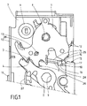
図1は、回転自在に取り付けられる回転ラッチ1および回転自在に取り付けられる爪部2を備える把持機構を示す。図1では、把持機構は中間施錠位置にある。回転ラッチ1の金属の回転防止面3は、爪部2の金属の回転防止面4に対して押し付けられる。したがって、回転ラッチ1は、開錠位置で、反時計方向に回転することができない。
FIG. 1 shows a gripping mechanism comprising a
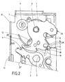
回転ラッチ1は、完全施錠位置で、爪部2の回転防止面4に対して押し付けられる、さらなる金属の回転防止面5を含む。図1に示す回転ラッチ1が時計方向にさらに回転すると、把持機構は最終的にこの完全施錠位置になるものと予想される。弾性材料から作成されるリングによって形成される停止部材6は、回転ラッチ1の、時計方向に加えて、図2に示すように反時計方向の回転運動を制限する。
The
プラスチックのロックハウジングの壁部7は、図1に示される回転ラッチ1の下方に位置付けられる。このプラスチックの壁部7の下方に、回転自在な取り付けを提供するために、金属の、具体的にはU字型の、回転ラッチおよび爪部の穴部8および9通って延在する軸を保持する、強化プレートが提供される。総じて、強化プレートは、ロックの切込み部の周りにU字型で延在する。U字の2つの脚部は、2つの前記軸を収容する穴部を含む。把持機構の図を遮らないように、ロックケースの金属の側壁10のみが示される。したがって、図1の金属のロックケースの基部は、回転ラッチ1の上方および爪部2の上方に位置付けられる。側壁10は、ロックケースの基部に対して直角に形成される。ロックハウジングの側方タブ11は、ロックケース側壁10の凹部に係合し、ロックハウジング壁部7をロックケースに固定する機能を果たす。ロックハウジング壁部7は、ロックハウジングの垂直壁12との一体部分を形成する。ロックハウジング壁部7から2つの壁部12への移行は、各々の場合、直角に形成される。ロックプレートの近接領域を含めて、壁部12は締め付けボルトのために切込み部を形成する。切込み部は、一方の側をロックハウジングの壁部によって覆うこともできる。壁部12は、内側がそれぞれに向かって漏斗状の形状であり、最終的に、エラストマーで作製される、回転ラッチの下方の平面上に位置付けられる、概してL字型の減衰部材の短い脚部13に向かって突き当たる。短い脚部13は、2つの壁領域12によって形成される漏斗状部の基部を打つ締め付けボルトをダンピングすることができる。短い脚部13は、したがって、減衰脚とも称される。
The
突出部15とは別に、好適には、L字型の減衰部材が配設され、独国特許出願公開第10320457A1号明細書に開示されるのと同一の様式で動作する。
Apart from the
減衰部材は、固定用脚部とも称される長い脚部14を含み、その端部では、突出部15は図1で上向きに延在するように配設される。突出部15は、回転ラッチ1の主たる回転防止面5に対する、把持機構の開錠位置での接触面16、および接触面24を備える、構成部品を構成する。回転ラッチ1の負荷アームの少なくとも側方曲線部25は、完全施錠位置で接触面24に突き当たる。減衰部材は、一体成形体であり、エラストマーから作製される突出部15を包含する。突出部15の2つの壁領域は、ロックハウジングの壁領域17に加えて、ロックハウジングのウェブ18によって支持される。支持壁領域17は、ロックケース表面7から見ると垂直上向きに延在する。ウェブ18は、同一の様式で、これも垂直上向きに延在する側壁を包含する。ウェブ18のかかる側壁は、垂直上向きに延在し、前記側壁に向かって突き当たる突出部15を支持する。
The damping member includes a
ロックハウジング壁部7は、当初は切込み部の側方の境界と平行に延び、この場合、ほとんど直線状の線形隆起部26を含む。具体的には、線形隆起部の一端は、減衰部材の持ち上がった領域に向かって、特に図3に示す減衰部材の段部23に当接し、または接触面を備えた構成部品の突出部15に直接向かう。切込み部の内側の端部上で、線形隆起部26は切込み部から離れ、停止部材6の方向に弓型形状で延びる。その回転移動の間、回転ラッチ1は常に線形隆起部26の上、したがって任意の位置に当接する。概して、線形隆起部は、ロックの内側に入る可能性のあるダストをより少なくするように貢献する。
The
それぞれの線形隆起部27が、爪部2のために提供される。爪部2は、この線形隆起部27上に、それぞれの位置で当接する。ここでも、これは、ロックの重要な部分に入るダストの量を低減する。
A respective
図2は、開錠位置にある把持機構を示す。回転ラッチ1の回転防止面5は、突出部15の接触面16に向かって上述の様式で当接し、ダストの侵入を防止する。円形の停止部材6は、回転ラッチ1の、反時計方向の回転移動も制限する。回転防止面4を包囲する爪部2のアームは、回転ラッチ1の側方の曲線部に向かって、前記ラッチを掛けることなく当接する。概して、接触面6は、回転ラッチ1の回転移動を、解錠方向に、すなわち図2で反時計方向に制限するために十分である。したがって、停止部材6は、移動を制限するために必要とは限らない。
FIG. 2 shows the gripping mechanism in the unlocked position. The anti-rotation surface 5 of the
図3は、短い脚部13、長い脚部14、および長い脚部14の一端から突出する突出部15を備える一体成形体減衰部材の好適な実施形態を示す。
FIG. 3 shows a preferred embodiment of an integrally molded body damping member comprising a
短い脚部13は、好適には凹部19を含み、側面20を打つ締め付けボルトの改善されたダンピングを提供する。長い脚部14は、好適には、穴部21の内径に対応し、好適にはわずかにより大きい外径を備える、ボルト(図示せず)がその中に挿入される、穴部21を含む。ボルトは、相当する非弾性材料、特に硬質プラスチック材料で作成される。これは、減衰部材が、好適にはボルトがその中クリップ留めされる、それぞれの凹部内へ挿入されるとき、減衰部材の安定性を改善する。凹部は、ロックハウジングによって形成することができ、または一体成形体を形成するように接続することができる。好適には、凹部は、結果として安定化される切込み部の壁部12によって部分的に形成される。選択的に提供された減衰部材のリブ付きの側面は、前記凹部の挿入を容易にする。好適には、突出部15を備える(上)面と対面する(下)面は、減衰部材の前記凹部内への挿入を制限し、ひいては正しい挿入を確実にする側方に突出する面22を含む。前記凹部は、挿入されたとき、減衰部材の凹部内への保持を改善するために、突出部15を備える(上)面と対面する(下)面に向かって突き当たる突出するタブを包含することができる。タブは、好適には、一体成形体を形成するようにロックハウジングにも接続される。(上)面上に選択的に提供された段部23は、突き当たる突出部15の安定性をさらに改善するために、この目的で提供されたスロット内に凹部内で挿入することができる。
The
1...回転ラッチ
2...爪部
3...中間施錠位置に対する回転防止面
4...爪部の回転防止面
5...完全施錠位置に対する金属の回転防止面
6...停止部材
7...ロックハウジング壁部
8...回転ラッチの穴部
9...爪部の穴部
10...ロックケースの金属の側壁
11...ロックハウジングの側方タブ
12...ロックハウジングの壁部
13...短い減衰脚
14...長い保持脚
15...突出形状の接触面を備えた構成部品
16...構成部品の接触面
17...ロックハウジングの壁領域
18...ロックハウジングのウェブ
19...減衰脚の凹部
20...減衰脚の側面
21...保持脚の穴部
22...側方に突出した減衰部材の面
23...減衰部材の段部
24...接触面
25...側方曲線部
26...回転ラッチに対する線形隆起部
27...爪部に対する線形隆起部
1 ...
Claims (12)
前記把持機構の開錠位置で、前記回転ラッチ(1)の回転防止面(5)が当接する、および/または前記把持機構の少なくとも1つのラッチ係合位置で、前記回転ラッチ(1)の表面(25)に当接する少なくとも1つの接触面(16)を備えた構成部品(15)を有するものであることを特徴とするロック。 A rotation latch (1), a claw portion (2) for latching engagement with the rotation latch, and a rotation preventing surface for latch engagement provided on the rotation latch (1) and the claw portion (2) ( 4 and 5) having a gripping mechanism,
The anti-rotation surface (5) of the rotation latch (1) abuts at the unlocking position of the gripping mechanism and / or the surface of the rotation latch (1) at at least one latch engagement position of the gripping mechanism A lock, characterized in that it has a component (15) with at least one contact surface (16) in contact with (25).
前記回転ラッチ(1)が置かれる、特に当該回転ラッチの各位置において置かれる線形隆起部(26)を有するものであるロック。 A lock according to any one of the preceding claims,
A lock having linear ridges (26) on which the rotating latch (1) is placed, in particular at each position of the rotating latch.
Applications Claiming Priority (3)
| Application Number | Priority Date | Filing Date | Title |
|---|---|---|---|
| DE102011003410A DE102011003410A1 (en) | 2011-01-31 | 2011-01-31 | Motor vehicle lock |
| DE102011003410.2 | 2011-01-31 | ||
| PCT/DE2012/000056 WO2012103865A2 (en) | 2011-01-31 | 2012-01-24 | Motor-vehicle lock |
Publications (3)
| Publication Number | Publication Date |
|---|---|
| JP2014509355A true JP2014509355A (en) | 2014-04-17 |
| JP2014509355A5 JP2014509355A5 (en) | 2015-03-19 |
| JP6000282B2 JP6000282B2 (en) | 2016-09-28 |
Family
ID=46275608
Family Applications (1)
| Application Number | Title | Priority Date | Filing Date |
|---|---|---|---|
| JP2013550756A Active JP6000282B2 (en) | 2011-01-31 | 2012-01-24 | Car door lock |
Country Status (6)
| Country | Link |
|---|---|
| EP (1) | EP2670934B1 (en) |
| JP (1) | JP6000282B2 (en) |
| KR (1) | KR101943121B1 (en) |
| CN (1) | CN103459741B (en) |
| DE (1) | DE102011003410A1 (en) |
| WO (1) | WO2012103865A2 (en) |
Families Citing this family (1)
| Publication number | Priority date | Publication date | Assignee | Title |
|---|---|---|---|---|
| DE102014114930A1 (en) * | 2014-10-15 | 2016-04-21 | Kiekert Ag | Motor vehicle door lock and associated method for producing such a motor vehicle door lock |
Citations (4)
| Publication number | Priority date | Publication date | Assignee | Title |
|---|---|---|---|---|
| JPS5112886B1 (en) * | 1968-08-22 | 1976-04-23 | ||
| JPS60161262U (en) * | 1984-04-04 | 1985-10-26 | 富士重工業株式会社 | Automotive door latch device |
| JP2005105809A (en) * | 2003-10-01 | 2005-04-21 | Kia Motors Corp | Door latch structure for vehicle |
| JP2006200252A (en) * | 2005-01-21 | 2006-08-03 | Aisin Seiki Co Ltd | Door lock for automobile |
Family Cites Families (8)
| Publication number | Priority date | Publication date | Assignee | Title |
|---|---|---|---|---|
| FR2561702B1 (en) * | 1984-03-20 | 1986-09-19 | Peugeot Aciers Et Outillage | ELECTROMECHANICAL DEVICE FOR CONTROLLING THE OPENING OF A MOTOR VEHICLE DOOR LOCK AND LOCK COMPRISING SUCH A DEVICE |
| CA1326502C (en) * | 1988-03-11 | 1994-01-25 | Wolfgang Thau | Latch mechanism, components thereof and process of manufacture for components thereof |
| FR2753738B1 (en) * | 1996-09-20 | 1998-11-27 | ELECTRIC LOCK MODULE FOR THE TRUNK OF A MOTOR VEHICLE | |
| JP3143601B2 (en) * | 1997-05-16 | 2001-03-07 | 三井金属鉱業株式会社 | Device to prevent forgetting the key inside the vehicle |
| DE10320457A1 (en) | 2003-05-08 | 2004-12-16 | Kiekert Ag | Motor vehicle door lock |
| DE202005020452U1 (en) * | 2005-12-29 | 2007-05-16 | Kiekert Ag | Motor vehicle door lock |
| DE102006006443A1 (en) | 2006-02-10 | 2007-08-23 | Kiekert Ag | Motor vehicle door lock |
| CN201457297U (en) * | 2009-07-27 | 2010-05-12 | 河南开开特星光锁系统有限公司 | Central centralized control automobile lock |
-
2011
- 2011-01-31 DE DE102011003410A patent/DE102011003410A1/en not_active Withdrawn
-
2012
- 2012-01-24 WO PCT/DE2012/000056 patent/WO2012103865A2/en active Application Filing
- 2012-01-24 JP JP2013550756A patent/JP6000282B2/en active Active
- 2012-01-24 EP EP12727228.4A patent/EP2670934B1/en active Active
- 2012-01-24 KR KR1020137022252A patent/KR101943121B1/en active IP Right Grant
- 2012-01-24 CN CN201280016848.2A patent/CN103459741B/en active Active
Patent Citations (4)
| Publication number | Priority date | Publication date | Assignee | Title |
|---|---|---|---|---|
| JPS5112886B1 (en) * | 1968-08-22 | 1976-04-23 | ||
| JPS60161262U (en) * | 1984-04-04 | 1985-10-26 | 富士重工業株式会社 | Automotive door latch device |
| JP2005105809A (en) * | 2003-10-01 | 2005-04-21 | Kia Motors Corp | Door latch structure for vehicle |
| JP2006200252A (en) * | 2005-01-21 | 2006-08-03 | Aisin Seiki Co Ltd | Door lock for automobile |
Also Published As
| Publication number | Publication date |
|---|---|
| EP2670934B1 (en) | 2017-07-19 |
| CN103459741B (en) | 2016-04-13 |
| KR101943121B1 (en) | 2019-01-28 |
| CN103459741A (en) | 2013-12-18 |
| KR20140008515A (en) | 2014-01-21 |
| EP2670934A2 (en) | 2013-12-11 |
| WO2012103865A2 (en) | 2012-08-09 |
| JP6000282B2 (en) | 2016-09-28 |
| DE102011003410A1 (en) | 2012-08-02 |
| WO2012103865A3 (en) | 2012-11-01 |
Similar Documents
| Publication | Publication Date | Title |
|---|---|---|
| JP5911843B2 (en) | Car door lock | |
| US20120018259A1 (en) | Blocking mechanism | |
| US9151092B2 (en) | Lock unit having a multi-pawl locking mechanism | |
| US20180229626A1 (en) | Longitudinal adjustment device for a vehicle seat and vehicle seat | |
| US20100052336A1 (en) | Lock device having a multi-part pawl | |
| US9617763B2 (en) | Lock for a vehicle door with a spring plate in the inlet region of the locking bolt | |
| US20060236732A1 (en) | Vibration-protected casement lock | |
| CN112867838B (en) | Motor vehicle lock | |
| JP5865521B2 (en) | Lock unit for vehicle seat | |
| US20140217753A1 (en) | Lock for a flap or door | |
| KR101673128B1 (en) | Locking device and a vehicle seat | |
| US9422754B2 (en) | Motor vehicle door lock | |
| US20160017643A1 (en) | Lock for a motor vehicle | |
| US20150354250A1 (en) | Motor vehicle door lock | |
| US8864192B2 (en) | Safety device for vehicle handles and vehicle handle comprising this safety device | |
| US10494839B2 (en) | Door latch apparatus for door for vehicle | |
| JP6000282B2 (en) | Car door lock | |
| JP4777131B2 (en) | Handle device | |
| JP2014510206A (en) | Flap or door lock | |
| CN111051633B (en) | Motor vehicle lock | |
| RU2616318C1 (en) | Handle device of vehicles | |
| JP4325794B2 (en) | Vehicle seat locking device | |
| KR101949792B1 (en) | Locking apparatus of manhole cover | |
| KR20090097707A (en) | Damping member for door latch assembly of vehicle | |
| RU2562032C2 (en) | Carrier opening part lock and rotary lug |
Legal Events
| Date | Code | Title | Description |
|---|---|---|---|
| A521 | Request for written amendment filed |
Free format text: JAPANESE INTERMEDIATE CODE: A523 Effective date: 20150124 |
|
| A621 | Written request for application examination |
Free format text: JAPANESE INTERMEDIATE CODE: A621 Effective date: 20150124 |
|
| A977 | Report on retrieval |
Free format text: JAPANESE INTERMEDIATE CODE: A971007 Effective date: 20151006 |
|
| A131 | Notification of reasons for refusal |
Free format text: JAPANESE INTERMEDIATE CODE: A131 Effective date: 20151020 |
|
| A521 | Request for written amendment filed |
Free format text: JAPANESE INTERMEDIATE CODE: A523 Effective date: 20160118 |
|
| RD03 | Notification of appointment of power of attorney |
Free format text: JAPANESE INTERMEDIATE CODE: A7423 Effective date: 20160620 |
|
| TRDD | Decision of grant or rejection written | ||
| A01 | Written decision to grant a patent or to grant a registration (utility model) |
Free format text: JAPANESE INTERMEDIATE CODE: A01 Effective date: 20160802 |
|
| A61 | First payment of annual fees (during grant procedure) |
Free format text: JAPANESE INTERMEDIATE CODE: A61 Effective date: 20160830 |
|
| R150 | Certificate of patent or registration of utility model |
Ref document number: 6000282 Country of ref document: JP Free format text: JAPANESE INTERMEDIATE CODE: R150 |
|
| R250 | Receipt of annual fees |
Free format text: JAPANESE INTERMEDIATE CODE: R250 |
|
| R250 | Receipt of annual fees |
Free format text: JAPANESE INTERMEDIATE CODE: R250 |
|
| R250 | Receipt of annual fees |
Free format text: JAPANESE INTERMEDIATE CODE: R250 |
|
| R250 | Receipt of annual fees |
Free format text: JAPANESE INTERMEDIATE CODE: R250 |
|
| R250 | Receipt of annual fees |
Free format text: JAPANESE INTERMEDIATE CODE: R250 |