JP2014507992A - Apparatus and method for monitoring cerebral hemodynamic status - Google Patents
Apparatus and method for monitoring cerebral hemodynamic status Download PDFInfo
- Publication number
- JP2014507992A JP2014507992A JP2013553048A JP2013553048A JP2014507992A JP 2014507992 A JP2014507992 A JP 2014507992A JP 2013553048 A JP2013553048 A JP 2013553048A JP 2013553048 A JP2013553048 A JP 2013553048A JP 2014507992 A JP2014507992 A JP 2014507992A
- Authority
- JP
- Japan
- Prior art keywords
- signal
- bioimpedance
- brain
- measurement device
- cerebral
- Prior art date
- Legal status (The legal status is an assumption and is not a legal conclusion. Google has not performed a legal analysis and makes no representation as to the accuracy of the status listed.)
- Pending
Links
- 238000000034 method Methods 0.000 title claims abstract description 53
- 230000000004 hemodynamic effect Effects 0.000 title claims abstract description 45
- 230000002490 cerebral effect Effects 0.000 title claims abstract description 43
- 238000012544 monitoring process Methods 0.000 title description 9
- 210000004556 brain Anatomy 0.000 claims abstract description 98
- 238000005259 measurement Methods 0.000 claims abstract description 61
- 230000000747 cardiac effect Effects 0.000 claims description 64
- 230000003727 cerebral blood flow Effects 0.000 claims description 23
- 239000008280 blood Substances 0.000 claims description 15
- 210000004369 blood Anatomy 0.000 claims description 14
- 230000001360 synchronised effect Effects 0.000 claims description 14
- 230000002596 correlated effect Effects 0.000 claims description 11
- 230000004962 physiological condition Effects 0.000 claims description 4
- 230000035790 physiological processes and functions Effects 0.000 claims description 4
- 230000003252 repetitive effect Effects 0.000 claims 2
- 210000003128 head Anatomy 0.000 description 42
- 230000006870 function Effects 0.000 description 25
- 230000017531 blood circulation Effects 0.000 description 22
- 238000004458 analytical method Methods 0.000 description 21
- 238000010586 diagram Methods 0.000 description 17
- 230000008859 change Effects 0.000 description 16
- 230000000875 corresponding effect Effects 0.000 description 11
- 238000001514 detection method Methods 0.000 description 10
- 210000001367 artery Anatomy 0.000 description 9
- 208000031104 Arterial Occlusive disease Diseases 0.000 description 8
- 208000006011 Stroke Diseases 0.000 description 8
- 208000021328 arterial occlusion Diseases 0.000 description 8
- 238000004422 calculation algorithm Methods 0.000 description 8
- 238000000354 decomposition reaction Methods 0.000 description 8
- 230000010412 perfusion Effects 0.000 description 7
- 208000032382 Ischaemic stroke Diseases 0.000 description 6
- 230000009471 action Effects 0.000 description 6
- 230000007423 decrease Effects 0.000 description 6
- 238000012545 processing Methods 0.000 description 6
- 238000001356 surgical procedure Methods 0.000 description 6
- 230000002123 temporal effect Effects 0.000 description 6
- 230000036770 blood supply Effects 0.000 description 5
- 210000004204 blood vessel Anatomy 0.000 description 5
- 230000003788 cerebral perfusion Effects 0.000 description 5
- 238000004891 communication Methods 0.000 description 5
- 208000020658 intracerebral hemorrhage Diseases 0.000 description 5
- 208000016988 Hemorrhagic Stroke Diseases 0.000 description 4
- 210000004004 carotid artery internal Anatomy 0.000 description 4
- 230000008602 contraction Effects 0.000 description 4
- 238000003745 diagnosis Methods 0.000 description 4
- 238000002595 magnetic resonance imaging Methods 0.000 description 4
- 239000000463 material Substances 0.000 description 4
- 230000000737 periodic effect Effects 0.000 description 4
- 230000004044 response Effects 0.000 description 4
- 210000005166 vasculature Anatomy 0.000 description 4
- 238000002583 angiography Methods 0.000 description 3
- 210000001765 aortic valve Anatomy 0.000 description 3
- 210000001841 basilar artery Anatomy 0.000 description 3
- 210000001627 cerebral artery Anatomy 0.000 description 3
- 238000006243 chemical reaction Methods 0.000 description 3
- 230000003205 diastolic effect Effects 0.000 description 3
- 230000002861 ventricular Effects 0.000 description 3
- 210000002551 anterior cerebral artery Anatomy 0.000 description 2
- 210000000709 aorta Anatomy 0.000 description 2
- 238000004364 calculation method Methods 0.000 description 2
- 210000001715 carotid artery Anatomy 0.000 description 2
- 230000007213 cerebrovascular event Effects 0.000 description 2
- 238000002591 computed tomography Methods 0.000 description 2
- 238000004590 computer program Methods 0.000 description 2
- 230000001934 delay Effects 0.000 description 2
- 230000003111 delayed effect Effects 0.000 description 2
- 238000001914 filtration Methods 0.000 description 2
- 210000001061 forehead Anatomy 0.000 description 2
- 238000007917 intracranial administration Methods 0.000 description 2
- 210000003205 muscle Anatomy 0.000 description 2
- 230000003287 optical effect Effects 0.000 description 2
- 210000003388 posterior cerebral artery Anatomy 0.000 description 2
- 238000007781 pre-processing Methods 0.000 description 2
- 210000004761 scalp Anatomy 0.000 description 2
- 238000001228 spectrum Methods 0.000 description 2
- 238000002604 ultrasonography Methods 0.000 description 2
- 210000002385 vertebral artery Anatomy 0.000 description 2
- 206010048962 Brain oedema Diseases 0.000 description 1
- 206010008111 Cerebral haemorrhage Diseases 0.000 description 1
- 206010019196 Head injury Diseases 0.000 description 1
- 238000012879 PET imaging Methods 0.000 description 1
- 239000000853 adhesive Substances 0.000 description 1
- 230000001070 adhesive effect Effects 0.000 description 1
- 210000003484 anatomy Anatomy 0.000 description 1
- 230000003416 augmentation Effects 0.000 description 1
- 230000005540 biological transmission Effects 0.000 description 1
- 208000006752 brain edema Diseases 0.000 description 1
- 210000005013 brain tissue Anatomy 0.000 description 1
- 210000001175 cerebrospinal fluid Anatomy 0.000 description 1
- 230000008455 cerebrovascular function Effects 0.000 description 1
- 210000003679 cervix uteri Anatomy 0.000 description 1
- 238000010968 computed tomography angiography Methods 0.000 description 1
- 238000012790 confirmation Methods 0.000 description 1
- 238000007796 conventional method Methods 0.000 description 1
- 230000007850 degeneration Effects 0.000 description 1
- 230000002542 deteriorative effect Effects 0.000 description 1
- 238000005315 distribution function Methods 0.000 description 1
- 210000000624 ear auricle Anatomy 0.000 description 1
- 230000000694 effects Effects 0.000 description 1
- 230000001747 exhibiting effect Effects 0.000 description 1
- 230000001815 facial effect Effects 0.000 description 1
- 239000006260 foam Substances 0.000 description 1
- 230000006872 improvement Effects 0.000 description 1
- 208000014674 injury Diseases 0.000 description 1
- 238000003780 insertion Methods 0.000 description 1
- 230000037431 insertion Effects 0.000 description 1
- 230000000302 ischemic effect Effects 0.000 description 1
- 230000007246 mechanism Effects 0.000 description 1
- 238000000491 multivariate analysis Methods 0.000 description 1
- 238000012636 positron electron tomography Methods 0.000 description 1
- 238000011002 quantification Methods 0.000 description 1
- 230000000241 respiratory effect Effects 0.000 description 1
- 239000000523 sample Substances 0.000 description 1
- 239000003381 stabilizer Substances 0.000 description 1
- 238000012360 testing method Methods 0.000 description 1
- 210000001519 tissue Anatomy 0.000 description 1
- 238000003325 tomography Methods 0.000 description 1
- 230000008733 trauma Effects 0.000 description 1
- 230000002792 vascular Effects 0.000 description 1
- 238000009423 ventilation Methods 0.000 description 1
- 230000000007 visual effect Effects 0.000 description 1
Images


Classifications
-
- A—HUMAN NECESSITIES
- A61—MEDICAL OR VETERINARY SCIENCE; HYGIENE
- A61B—DIAGNOSIS; SURGERY; IDENTIFICATION
- A61B5/00—Measuring for diagnostic purposes; Identification of persons
- A61B5/02—Detecting, measuring or recording pulse, heart rate, blood pressure or blood flow; Combined pulse/heart-rate/blood pressure determination; Evaluating a cardiovascular condition not otherwise provided for, e.g. using combinations of techniques provided for in this group with electrocardiography or electroauscultation; Heart catheters for measuring blood pressure
- A61B5/026—Measuring blood flow
- A61B5/0265—Measuring blood flow using electromagnetic means, e.g. electromagnetic flowmeter
-
- A—HUMAN NECESSITIES
- A61—MEDICAL OR VETERINARY SCIENCE; HYGIENE
- A61B—DIAGNOSIS; SURGERY; IDENTIFICATION
- A61B5/00—Measuring for diagnostic purposes; Identification of persons
- A61B5/02—Detecting, measuring or recording pulse, heart rate, blood pressure or blood flow; Combined pulse/heart-rate/blood pressure determination; Evaluating a cardiovascular condition not otherwise provided for, e.g. using combinations of techniques provided for in this group with electrocardiography or electroauscultation; Heart catheters for measuring blood pressure
- A61B5/026—Measuring blood flow
- A61B5/0295—Measuring blood flow using plethysmography, i.e. measuring the variations in the volume of a body part as modified by the circulation of blood therethrough, e.g. impedance plethysmography
-
- A—HUMAN NECESSITIES
- A61—MEDICAL OR VETERINARY SCIENCE; HYGIENE
- A61B—DIAGNOSIS; SURGERY; IDENTIFICATION
- A61B5/00—Measuring for diagnostic purposes; Identification of persons
- A61B5/05—Detecting, measuring or recording for diagnosis by means of electric currents or magnetic fields; Measuring using microwaves or radio waves
- A61B5/053—Measuring electrical impedance or conductance of a portion of the body
- A61B5/0535—Impedance plethysmography
-
- A—HUMAN NECESSITIES
- A61—MEDICAL OR VETERINARY SCIENCE; HYGIENE
- A61B—DIAGNOSIS; SURGERY; IDENTIFICATION
- A61B5/00—Measuring for diagnostic purposes; Identification of persons
- A61B5/40—Detecting, measuring or recording for evaluating the nervous system
- A61B5/4058—Detecting, measuring or recording for evaluating the nervous system for evaluating the central nervous system
- A61B5/4064—Evaluating the brain
-
- A—HUMAN NECESSITIES
- A61—MEDICAL OR VETERINARY SCIENCE; HYGIENE
- A61B—DIAGNOSIS; SURGERY; IDENTIFICATION
- A61B5/00—Measuring for diagnostic purposes; Identification of persons
- A61B5/68—Arrangements of detecting, measuring or recording means, e.g. sensors, in relation to patient
- A61B5/6801—Arrangements of detecting, measuring or recording means, e.g. sensors, in relation to patient specially adapted to be attached to or worn on the body surface
- A61B5/6802—Sensor mounted on worn items
- A61B5/6803—Head-worn items, e.g. helmets, masks, headphones or goggles
-
- A—HUMAN NECESSITIES
- A61—MEDICAL OR VETERINARY SCIENCE; HYGIENE
- A61B—DIAGNOSIS; SURGERY; IDENTIFICATION
- A61B5/00—Measuring for diagnostic purposes; Identification of persons
- A61B5/72—Signal processing specially adapted for physiological signals or for diagnostic purposes
- A61B5/7235—Details of waveform analysis
- A61B5/7246—Details of waveform analysis using correlation, e.g. template matching or determination of similarity
-
- A—HUMAN NECESSITIES
- A61—MEDICAL OR VETERINARY SCIENCE; HYGIENE
- A61B—DIAGNOSIS; SURGERY; IDENTIFICATION
- A61B5/00—Measuring for diagnostic purposes; Identification of persons
- A61B5/68—Arrangements of detecting, measuring or recording means, e.g. sensors, in relation to patient
- A61B5/6801—Arrangements of detecting, measuring or recording means, e.g. sensors, in relation to patient specially adapted to be attached to or worn on the body surface
- A61B5/6813—Specially adapted to be attached to a specific body part
- A61B5/6814—Head
Landscapes
- Health & Medical Sciences (AREA)
- Life Sciences & Earth Sciences (AREA)
- Physics & Mathematics (AREA)
- Engineering & Computer Science (AREA)
- Public Health (AREA)
- Veterinary Medicine (AREA)
- Biophysics (AREA)
- Pathology (AREA)
- General Health & Medical Sciences (AREA)
- Biomedical Technology (AREA)
- Heart & Thoracic Surgery (AREA)
- Medical Informatics (AREA)
- Molecular Biology (AREA)
- Surgery (AREA)
- Animal Behavior & Ethology (AREA)
- Physiology (AREA)
- Neurology (AREA)
- Hematology (AREA)
- Cardiology (AREA)
- Radiology & Medical Imaging (AREA)
- Nuclear Medicine, Radiotherapy & Molecular Imaging (AREA)
- Psychology (AREA)
- Neurosurgery (AREA)
- Electromagnetism (AREA)
- Artificial Intelligence (AREA)
- Computer Vision & Pattern Recognition (AREA)
- Psychiatry (AREA)
- Signal Processing (AREA)
- Measuring Pulse, Heart Rate, Blood Pressure Or Blood Flow (AREA)
- Measurement And Recording Of Electrical Phenomena And Electrical Characteristics Of The Living Body (AREA)
- Measurement Of The Respiration, Hearing Ability, Form, And Blood Characteristics Of Living Organisms (AREA)
- Measuring And Recording Apparatus For Diagnosis (AREA)
Abstract
脳血液動態信号を予測するためのデバイスおよび方法が開示される。1つの局面において、これらのデバイスおよび方法は、生体インピーダンス測定値を特徴付ける少なくとも1つの信号を受信することを含み得る。前記少なくとも1つの信号を心臓波のタイミングと相関させ、分析することにより、前記信号内の予想特性の程度が確認される。予想特性の程度は、生理学的脳状態を予測するための情報を提供するために用いられ得る。前記少なくとも1つの信号は、対向する脳半球から取得された少なくとも2つの信号を含み得、生体インピーダンス信号であり得る。
【選択図】なしDevices and methods for predicting cerebral hemodynamic signals are disclosed. In one aspect, these devices and methods can include receiving at least one signal that characterizes a bioimpedance measurement. By correlating and analyzing the at least one signal with the timing of the heart wave, the degree of expected characteristics in the signal is ascertained. The degree of predictive characteristics can be used to provide information for predicting a physiological brain state. The at least one signal may include at least two signals obtained from opposing hemispheres and may be a bioimpedance signal.
[Selection figure] None
Description
(関連出願)
本出願は、米国仮出願第61/441,248号(出願日:2011年2月9日)および米国仮出願第61/474,739号(出願日:2011年4月12日)の合衆国法典第 35 巻119条(e)項の下の優先権の利益を主張する。本明細書中、これらの文献双方の全体を参考のため援用する。
(Related application)
This application is a United States Code of Provisional Application No. 61 / 441,248 (Filing Date: February 9, 2011) and United States Provisional Application No. 61 / 474,739 (Filing Date: April 12, 2011). Claims the interests of priority under Volume 35, paragraph 119 (e). In this specification, both of these documents are incorporated by reference in their entirety.
(技術分野)
本開示の局面は、頭部生体インピーダンス測定を特徴付ける信号の検出、監視および/または分析、およびそのような分析に基づく生理学的脳状態の予測に関する。
(Technical field)
Aspects of the present disclosure relate to the detection, monitoring and / or analysis of signals characterizing head bioimpedance measurements, and the prediction of physiological brain conditions based on such analysis.
複数の脳血液動態特性は、脳卒中、外傷、および脳血管系の機能に影響を与え得る他の状態の診断において臨床的に有用であり得る。これらの特性を挙げると、脳血液量、脳血流、脳かん流圧、平均通過時間、ピーク到達までの時間、頭蓋内圧などがある。これらのパラメータの検出または監視のための従来の方法を挙げると、脳脊髄液または動脈内へのプローブの物理的挿入、血管造影、CT血管造影(CTA)、かん流コンピュータ断層撮影(PCT)、経頭蓋ドップラー超音波法(TCD)、陽電子断層撮影法(PET)、および磁気共鳴映像法(MRI)および血管造影(MRA)がある。 Multiple cerebral hemodynamic properties may be clinically useful in the diagnosis of stroke, trauma, and other conditions that may affect cerebrovascular function. These characteristics include cerebral blood volume, cerebral blood flow, cerebral perfusion pressure, average transit time, time to peak, and intracranial pressure. Conventional methods for detection or monitoring of these parameters include physical insertion of the probe into the cerebrospinal fluid or artery, angiography, CT angiography (CTA), perfusion computed tomography (PCT), There are transcranial Doppler ultrasound (TCD), positron tomography (PET), and magnetic resonance imaging (MRI) and angiography (MRA).
脳血液動態パラメータの検出または監視のためのいくつかの非侵襲的方法の場合、例えば、CT、PCT、PETおよび/またはMRI行為を行うための機器が必要になり得る。場合によっては、これらの機器のコスト、可動度における制約および/または使用毎の高コストに起因して、脳血液動態特性の監視を定期的、連続的または頻繁に行うことが望ましい場合であってもその有用性が限定される場合がある。 For some non-invasive methods for the detection or monitoring of cerebral hemodynamic parameters, for example, equipment for performing CT, PCT, PET and / or MRI actions may be required. In some cases, it may be desirable to monitor cerebral hemodynamic properties regularly, continuously or frequently due to the cost, mobility constraints and / or high cost of use of these devices. However, its usefulness may be limited.
上記の記載は、一般的な背景を述べるための単なる例示であり、上記および特許請求の範囲中に記載のシステム、方法、デバイスおよびフィーチャの多様な実施形態を限定しない。 The above description is merely illustrative to provide a general background, and does not limit various embodiments of the systems, methods, devices, and features described above and in the claims.
本開示の実施形態において、脳血管血液動態特性の検出および監視に用いることが可能な方法およびシステムをいくつか記載する。いくつかの実施形態において、これらの方法およびシステムは、例えば連続的または頻繁な使用において有用であり得、例えば患者ヘッドセットおよび脳かん流モニタを用い得る。上記例えば患者ヘッドセットおよび脳かん流モニタは、脳血管血液動態特性を示す信号の同期化および監視に用いられる。上記患者ヘッドセットおよび脳かん流モニタから、動脈閉塞(例えば、虚血性脳卒中または頭部外傷に起因する閉塞)の変化を診断するための情報を得ることができる。 In embodiments of the present disclosure, several methods and systems are described that can be used to detect and monitor cerebrovascular hemodynamic characteristics. In some embodiments, these methods and systems may be useful, for example, in continuous or frequent use, such as using a patient headset and a brain perfusion monitor. Such patient headsets and cerebral perfusion monitors, for example, are used to synchronize and monitor signals indicative of cerebrovascular hemodynamic characteristics. Information for diagnosing changes in arterial occlusion (eg, occlusion due to ischemic stroke or head trauma) can be obtained from the patient headset and cerebral perfusion monitor.
1つの例示的な開示の実施形態は、脳血液動態測定装置を含み得る。この装置は、上述のように、少なくとも1つの頭部生体インピーダンス測定値を特徴付ける少なくとも1つの信号を受信するよう構成された、少なくとも1つのプロセッサを備え得る。前記少なくとも1つのプロセッサは、前記少なくとも1つの信号と心臓波とを相関させるようさらに構成され得る。前記少なくとも1つのプロセッサは、前記心臓波により規定される時間的期間中の少なくとも1つの信号を分析することにより、前記時間的期間中の前記少なくとも1つの信号における少なくとも1つの予想特性の程度を確認し、前記少なくとも1つの信号における前記少なくとも1つの予想特性の程度に基づいて生理学的脳状態を予測するための情報を出力するよう、さらに構成され得る。 One exemplary disclosed embodiment may include a cerebral hemodynamic measurement device. The apparatus may comprise at least one processor configured to receive at least one signal characterizing at least one head bioimpedance measurement, as described above. The at least one processor may be further configured to correlate the at least one signal with a heart wave. The at least one processor determines the degree of at least one expected characteristic in the at least one signal during the time period by analyzing at least one signal during the time period defined by the heart wave And may be further configured to output information for predicting a physiological brain state based on the degree of the at least one expected characteristic in the at least one signal.
他の実施形態において、前記少なくとも1つの信号は、それぞれが対象者の脳の異なる脳半球に関する少なくとも2つの生体インピーダンス信号を含み得、前記少なくとも2つの生体インピーダンス信号は相互に対して同期される。 In another embodiment, the at least one signal may include at least two bioimpedance signals, each relating to a different hemisphere of the subject's brain, wherein the at least two bioimpedance signals are synchronized with each other.
他の実施形態において、前記少なくとも1つの予想特性は、生体インピーダンス信号におけるフィーチャの高さ、遅延、幅、およびタイミングのうちの少なくとも1つに関し得るか、または生体インピーダンス信号における第1のピーク、第2のピーク、および第3のピークのうちの少なくとも1つに関し得る。前記少なくとも1つの予想特性は、ピーク位置、最小値位置、予測されるピーク位置、および予測される最小値位置のうちの1つ以上を含み得る。 In other embodiments, the at least one expected characteristic may relate to at least one of feature height, delay, width, and timing in the bioimpedance signal, or a first peak, It may relate to at least one of the second peak and the third peak. The at least one prediction characteristic may include one or more of a peak position, a minimum position, a predicted peak position, and a predicted minimum position.
さらに他の実施形態において、前記少なくとも1つの信号は、対象者の脳の第1の脳半球に関する第1の信号と対象者の脳の第2の脳半球に関する第2の信号とを含み得る。なお、前記プロセッサは、前記第1の信号の部分と前記第2の信号の部分との比較に少なくとも部分的に基づいて生理学的脳状態を予測するよう構成される。 In still other embodiments, the at least one signal may include a first signal related to a first hemisphere of the subject's brain and a second signal related to a second hemisphere of the subject's brain. The processor is configured to predict a physiological brain state based at least in part on a comparison of the first signal portion and the second signal portion.
さらに別の実施形態において、上記プロセッサは、心臓波により定められる事前規定された対象時間的期間中の前記第1の信号および前記第2の信号のうちの少なくとも1つの部分を分析するようさらに構成され得る。 In yet another embodiment, the processor is further configured to analyze at least a portion of the first signal and the second signal during a predefined target time period defined by a heart wave. Can be done.
他の実施形態において、分析することは、前記少なくとも1つの信号を、前記少なくとも1つの予想特性と前記少なくとも1つの信号との間の相関程度に基づく予測に適合させることを含み得る。 In other embodiments, analyzing may include adapting the at least one signal to a prediction based on a degree of correlation between the at least one prediction characteristic and the at least one signal.
さらに他の実施形態において、前記プロセッサは、前記少なくとも1つの信号におけるフィーチャを脳血流画像情報で較正するようさらに構成され得る。 In yet other embodiments, the processor may be further configured to calibrate features in the at least one signal with cerebral blood flow image information.
さらなる実施形態において、分析することは、表示された生理学的状態に基づいて、予想特性付近の時間的期間に注目することを含み得る。 In further embodiments, analyzing may include focusing on a time period near the expected characteristic based on the displayed physiological state.
追加的な実施形態において、相関させることは、前記少なくとも1つの信号と同時心臓周期のタイミングとを同期することを含み得る。相関させることは、前記少なくとも1つの信号の部分と心臓周期に以前に相関された既知の信号とを比較することにより、前記少なくとも1つの信号と心臓周期とのタイミングの一致を検出することも含み得る。 In additional embodiments, correlating may include synchronizing the at least one signal with the timing of a simultaneous cardiac cycle. Correlating also includes detecting a timing match between the at least one signal and the cardiac cycle by comparing the portion of the at least one signal with a known signal previously correlated to the cardiac cycle. obtain.
相関のために用いられる心臓波は、ECGの任意の反復部分を含み得る。相関のために用いられる心臓波は、ECGR波であり得る。心臓波により規定される時間的期間は心臓周期の少なくとも2つの反復を含み得る。 The heart wave used for correlation may include any repeated portion of the ECG. The heart wave used for correlation can be an ECGR wave. The time period defined by the heart wave may include at least two repetitions of the cardiac cycle.
上記の概要、以下の図面の説明および以下の詳細な説明はひとえに本開示に関するわずか少数の例示と説明とのためのものであり、特許請求の範囲に記載の本発明を限定するものではない。 The above summary, the following description of the drawings and the following detailed description are for the purpose of illustrating only a few examples and explanations relating to the present disclosure and are not intended to limit the invention as claimed.
添付の図面は、本明細書において採用されかつ本明細書の一部を構成し、以下の記載と共に、本明細書中に記載の実施形態の原理を説明する役割を担う。 The accompanying drawings are employed herein and constitute a part of this specification, and together with the following description serve to explain the principles of the embodiments described herein.
ここで、添付図面を参照して例示的実施形態を詳細参照する。可能な場合は必ず、図面および以下の記載中、同一または類似の部分を示す場合、同一参照符号が用いられる。これらの実施形態について、当業者が本発明を実施できるように充分に詳細に説明する。他の実施形態も利用可能であり、本発明の範囲から逸脱することなく変更が可能であることが理解されるべきである。よって、以下の詳細な説明は、限定的な意味にとられるべきではない。 Reference will now be made in detail to exemplary embodiments with reference to the accompanying drawings. Wherever possible, the same reference numbers are used in the drawings and the following description to refer to the same or like parts. These embodiments are described in sufficient detail to enable those skilled in the art to practice the invention. It should be understood that other embodiments may be utilized and changes may be made without departing from the scope of the present invention. The following detailed description is, therefore, not to be taken in a limiting sense.
他に明記無き限り、本明細書中において用いられる技術用語および/または科学用語は全て、本発明の実施形態に関連する分野の当業者が理解する意味と同じ意味を有する。本発明の実施形態の実行または試験において本明細書中に記載のものと同様または相当する方法および材料を用いることが可能であるが、例示的な方法および/または材料について記載する。矛盾がある場合、特許明細書(定義を含む)が優先される。加えて、これらの物質、方法、および例は、単に例示的であり、限定を意図するものではない。 Unless defined otherwise, all technical and / or scientific terms used herein have the same meaning as understood by one of ordinary skill in the areas relevant to the embodiments of the present invention. Although methods and materials similar or equivalent to those described herein can be used in the practice or testing of embodiments of the present invention, exemplary methods and / or materials are described. In case of conflict, the patent specification (including definitions) will prevail. In addition, these materials, methods, and examples are illustrative only and not intended to be limiting.
例示的な開示の実施形態は、生体インピーダンス測定値を特徴付ける信号の検出および監視のためのデバイスおよび方法を含み得る。より詳細には、例示的な開示の実施形態は、信号の受信、相関、および分析を行い、生理学的脳状態の予測のための情報を出力するための装置を含み得る。 Exemplary disclosed embodiments may include devices and methods for detection and monitoring of signals that characterize bioimpedance measurements. More particularly, exemplary disclosed embodiments may include an apparatus for receiving, correlating, and analyzing signals and outputting information for prediction of physiological brain conditions.
本開示による実施形態は脳血液動態測定装置を含み得る。そのような装置は、脳血液動態特性の測定を支援するにあたり好適である要素および特徴を含み得る。脳血液動態測定装置は、例えば、支持要素(ヘッドセット、ヘッドバンド、または追加的な機能的要素を坦持または収容するための他の枠組要素)を含み得る(しかし、必ずしも含むとは限らない)。さらに組み込まれる構造を挙げると、電極と、回路と、プロセッサと、センサーと、ワイヤと、送信器と、受信器と、電気信号の取得、処理、送信、受信、および分析に好適である他のデバイスとがある。脳血液動態測定装置は、加えて、締結具と、接着物と、対象者の身体への取り付けを支援するためのその他の要素とを含み得る。本明細書において用いられる脳血液動態測定装置はこれらの特徴を全て含む必要はない。 Embodiments according to the present disclosure may include a cerebral hemodynamic measurement device. Such a device may include elements and features that are suitable for assisting in the measurement of cerebral hemodynamic properties. The cerebral hemodynamic measurement device may include (but need not necessarily include), for example, a support element (a headset, headband, or other framework element for carrying or housing additional functional elements). ). Further to be incorporated structures are electrodes, circuits, processors, sensors, wires, transmitters, receivers and other suitable for acquiring, processing, transmitting, receiving and analyzing electrical signals There is a device. The cerebral hemodynamic measurement device may additionally include fasteners, adhesives, and other elements to assist in attachment to the subject's body. The cerebral hemodynamic measurement device used in this specification need not include all of these features.
図1は、例示的な脳血液動態測定装置100の模式図である。この例示的な装置100は、電極110を含み得る。電極110は、ヘッドセット120を介して対象者頭部へと固定される。電極110は、ワイヤを介して脳かん流モニタ130に接続してもよいし、(あるいは無線接続を含み得る)。
FIG. 1 is a schematic diagram of an exemplary cerebral
本開示によるいくつかの実施形態において、脳血液動態測定装置は少なくとも1つのプロセッサを含み得る。前記少なくとも1つのプロセッサはアクションを実行するよう構成される。本明細書中用いられる「プロセッサ」という用語は、入力(単数または複数)上に論理演算を行う電気回路を含み得る。例えば、このようなプロセッサは、1つ以上の集積回路、マイクロチップ、マイクロコントローラ、マイクロプロセッサ、中央処理装置(CPU)の全体または一部、グラフィック処理ユニット(GPU)、デジタル信号プロセッサ(DSP)、フィールドプログラマブルゲートアレイ(FPGA)、あるいは命令実行または論理演算実行に適した他の回路を含み得る。上記少なくとも1つのプロセッサは、アクションを行うように構成される(ただし、上記少なくとも1つのプロセッサが上記アクションを実行せよとの命令と共にプログラムされている場合、上記アクションを実行せよとの命令を含む場合、または上記アクションを実行せよとの命令を実行可能なように構成されている場合)。上記少なくとも1つのプロセッサには、プロセッサ中に恒久的または一時的に保存された情報を通じてこのような命令が提供されるか、または、プロセッサへアクセスまたは提供される命令を通じて提供され得る。上記プロセッサへと提供された命令は、情報キャリア上にタンジブルに具現化された(例えば、機械可読保存デバイスまたは任意のタンジブルなコンピュータで読み出し可能な媒体中に具現化された)命令を含むコンピュータプログラムの形態で提供され得る。コンピュータプログラムは、任意の形態でプログラミング言語(例えば、コンパイラ型言語またはインタープリタ型言語)で書くことができ、任意の形態で展開することができる(例えば、スタンドアロンプログラムとしてまたは1つ以上のモジュール、コンポーネント、サブルーチンまたはコンピューティング環境において適切に用いられる他の単位)。上記少なくとも1つのプロセッサは、特殊ハードウエア、一般的ハードウエア、または関連命令を実行するためのこれらの組み合わせを含み得る。上記プロセッサはまた、統合通信インターフェースを含み得、あるいは、通信インターフェースを上記プロセッサと別個に設けてもよい。上記少なくとも1つのプロセッサは、特定の機能を行うための命令が保存されたメモリ位置または保存デバイスへの接続を通じて、当該機能を行うように構成され得る。 In some embodiments according to the present disclosure, the cerebral hemodynamic measurement device may include at least one processor. The at least one processor is configured to perform an action. The term “processor” as used herein may include an electrical circuit that performs logical operations on input (s). For example, such a processor may include one or more integrated circuits, a microchip, a microcontroller, a microprocessor, all or part of a central processing unit (CPU), a graphics processing unit (GPU), a digital signal processor (DSP), It may include a field programmable gate array (FPGA) or other circuitry suitable for instruction execution or logic operation execution. The at least one processor is configured to perform an action (provided that the at least one processor includes an instruction to perform the action if the at least one processor is programmed with an instruction to perform the action) Or if it is configured to execute an instruction to perform the above action). The at least one processor may be provided with such instructions through information stored permanently or temporarily in the processor, or may be provided through instructions accessed or provided to the processor. The instructions provided to the processor include a computer program comprising instructions tangibly embodied on an information carrier (eg, embodied in a machine readable storage device or any tangible computer readable medium). Can be provided. A computer program can be written in any form in a programming language (eg, a compiled or interpreted language) and can be deployed in any form (eg, as a stand-alone program or one or more modules, components) , Subroutines or other units suitably used in computing environments). The at least one processor may include special hardware, general hardware, or a combination thereof for executing related instructions. The processor may also include an integrated communication interface, or the communication interface may be provided separately from the processor. The at least one processor may be configured to perform that function through a connection to a memory location or storage device where instructions for performing a particular function are stored.
本発明のいくつかの実施形態によれば、上記少なくとも1つのプロセッサは、信号を受信するように構成され得る。本明細書中用いられる「信号」とは、任意の時間または空間と共に変化する数量であり得る。信号を受信することは、伝導手段(例えば、ワイヤまたは回路)を通じた信号受信、無線送信された信号の受信、および/または前回記録された信号(例えば、メモリ中に保存された信号)の受信を含み得る。信号を受信することは、当該分野において公知の他の信号受信方法をさらに含み得る。 According to some embodiments of the invention, the at least one processor may be configured to receive a signal. As used herein, a “signal” may be a quantity that varies with any time or space. Receiving the signal includes receiving a signal through a conducting means (eg, wire or circuit), receiving a wirelessly transmitted signal, and / or receiving a previously recorded signal (eg, a signal stored in memory). Can be included. Receiving the signal may further include other signal receiving methods known in the art.
少なくとも1つの頭部生体インピーダンス測定値を特徴付ける信号の受信、相関、および分析を行うよう構成された図1において示される少なくとも1つのプロセッサ160は、例示的な脳血液動態測定装置100の一部として、脳かん流モニタ130に含まれ得る。プロセッサ160は、本明細書中に記載する信号分析方法のうちの全体または一部を行うように構成してもよいし、あるいは、これらの機能のうちのいくつかは別個のプロセッサにより実行されるよう構成してもよい。プロセッサ160は、当業者に公知の任意の共通する信号処理タスク(例えば、フィルタリング、ノイズ除去、その他)を行うように構成してもよい。プロセッサ160は、さらに本明細書中に記載の信号分析技術に特有の前処理タスクを行うように構成することもできる。このような前処理タスクを非限定的に挙げると、信号アーチファクト(例えば、動きアーチファクトおよび呼吸アーチファクト)の除去がある。
As part of the exemplary cerebral
少なくとも1つの生体インピーダンス測定値を特徴付ける信号は、生体対象者の電気インピーダンスについての情報を含む任意の種類の信号を含み得る。そのような信号は、対象者の身体の任意の2つの部分間における対象者の電気インピーダンスについての情報を含み得る。上記対象者の電気インピーダンスについての情報は、電気インピーダンスの抵抗成分および/または反応成分についての情報を含み得る。 The signal characterizing the at least one bioimpedance measurement may include any type of signal that includes information about the electrical impedance of the living subject. Such a signal may include information about the subject's electrical impedance between any two parts of the subject's body. The information about the subject's electrical impedance may include information about the resistance component and / or reaction component of the electrical impedance.
本開示によれば、いくつかの例示的な実施形態において、少なくとも1つの頭部生体インピーダンス測定値を特徴付ける信号は、生体インピーダンス信号(インピーダンスプレチスモグラフィー信号)または光−血量計信号であり得る。生体インピーダンス信号は、少なくとも1つの電圧信号、および/または少なくとも1つの電流信号を含み得る。生体インピーダンス信号は、2つ以上の電圧信号および/または電流信号を含み得、2つ以上の電圧信号および/または電流信号間の比較を示す信号を含み得る。生体インピーダンス信号は、少なくとも1つの測定電圧信号および/または少なくとも1つの測定電流信号に対する応答として測定することができる。生体インピーダンス信号において、対象者の身体の電気インピーダンスについての情報は、信号の振幅、周波数または位相角中に含まれ得る。また、対象者の身体の電気インピーダンスについての情報は、複数の信号の振幅、周波数または位相角間の比較において含まれ得る。生体インピーダンス信号は、例えば、対象者の脳の第1の脳半球内のおよび/または第2の脳半球内の血液動態特性を示し得る。血液動態特性を挙げると、例えば、脳血液量、脳血流、脳かん流圧、頭蓋内圧、および脳状態を少なくとも部分的に表し得る任意の他のパラメータなどがある。第1の脳半球および第2の脳半球は、対象者の脳の右脳半球および左脳半球を任意の順序で指し得る。対象者の脳の特定の側部内の血液動態特性を示す信号は、電極などを介して上記対象者頭部の同一側部から得ることもできるし、あるいは上記対象者頭部の反対側側部から得ることもできる。あるいは、対象者の脳の特定の側部内の血液動態特性を示す信号は、他の位置からも得ることができる(例えば、対象者の(例えば頚動脈が存在する)頚部)。 According to the present disclosure, in some exemplary embodiments, the signal characterizing at least one head bioimpedance measurement may be a bioimpedance signal (impedance plethysmography signal) or a light-blood meter signal. . The bioimpedance signal may include at least one voltage signal and / or at least one current signal. The bioimpedance signal may include two or more voltage and / or current signals and may include a signal that indicates a comparison between the two or more voltage and / or current signals. The bioimpedance signal can be measured in response to at least one measurement voltage signal and / or at least one measurement current signal. In a bioimpedance signal, information about the electrical impedance of the subject's body can be included in the amplitude, frequency or phase angle of the signal. Also, information about the electrical impedance of the subject's body may be included in a comparison between the amplitude, frequency or phase angle of multiple signals. The bioimpedance signal may indicate, for example, hemodynamic characteristics in the first hemisphere and / or in the second hemisphere of the subject's brain. Hemodynamic characteristics include, for example, cerebral blood volume, cerebral blood flow, cerebral perfusion pressure, intracranial pressure, and any other parameter that can at least partially represent brain status. The first and second hemispheres may refer to the right and left hemispheres of the subject's brain in any order. A signal indicating hemodynamic characteristics in a specific side of the subject's brain can be obtained from the same side of the subject's head via an electrode or the like, or the opposite side of the subject's head You can also get from Alternatively, signals indicative of hemodynamic characteristics within a particular side of the subject's brain can also be obtained from other locations (eg, the subject's neck (eg, where the carotid artery is present)).
プロセッサ160は、図1の例示的なヘッドセット120に含まれる1つ以上の電極110から信号を受信するよう構成され得る。電極110は、実行様態に応じて、単一で配置してもよいし、複数対として配置してもよいし、あるいは適切なグループ分けで配置してもよい。例示的なヘッドセット120上の電極は生体インピーダンス信号波形を得るように配置することができる。生体インピーダンスは、2つのセンサー部150によって測定され得る。これらのセンサー部150は、例えば脳の右脳半球および左脳半球に対応するように、頭部の右側部および左側部上に配置される。図1中にはセンサー部150を1つだけ図示しているが、対象者頭部の反対側側部は、同様の電極配置を含み得る。各センサー部150は、一対の前電極、前電流電極111および前電圧電極112と、一対の後電極、後電流電極114および後電圧電極113とを含み得る。以下にさらに詳述するように、脳血液動態状態の特定の局面を測定できるように、上記対間の距離を調節する。図1に示す電極構成は、好適な電極構成の一例に過ぎない。さらなる実施形態として、1つよりも多数または少数の電極110を追加的にまたは代替的に例示的なヘッドセット120内の異なる領域に配置する。他の実施形態を挙げると、例示的なヘッドセット120以外の対象者頭部の異なる領域に到達するように代替的に形成されたヘッドセット上に構成された電極110がある。
The
複数対の電極110は、電流出力電極および電圧入力電極を含み得る。例えば、前電流電極111および前電圧電極112は、一対の電極を形成し得る。一実施形態において、出力電流が脳かん流モニタ130によって生成され、前電流電極111と後電流電極114との間に送られ得る。上記出力電流は、一定の振幅および安定した周波数を有する交流(AC)信号を含み得る。上記出力電流に起因して頭部上に発生した入力電圧を、前電圧電極112と後電圧電極113との間で測定することができる。入力電圧は、出力電流と同じ周波数で測定され得る。上記出力電流信号と上記入力電圧信号とを比較することにより、対象者の生体インピーダンスに関する情報を得ることができる。より詳細には、生体インピーダンスの振幅を入力電圧信号振幅と出力電流振幅信号との間の比として計算することができ、出力電流信号に起因して入力電圧信号を発生させる位相差として生体インピーダンスの位相を計算することができる。
The multiple pairs of
生体インピーダンス信号はまた、単一よりも多いAC周波数において出力電流を含み得る。上記出力電流は、全ての周波数または周波数範囲の一部における測定電圧を検出することにより、1組の事前規定された周波数および振幅を含み得る。 The bioimpedance signal may also include output current at more than a single AC frequency. The output current may include a set of predefined frequencies and amplitudes by detecting a measured voltage at all frequencies or portions of a frequency range.
別の実施形態において、第1の生体インピーダンス信号および第2の生体インピーダンス信号は、異なる周波数における出力AC電流を含み得る。例えば、頭部の一側部上に配置された電極からの電流が、1つの周波数において出力され得、上記頭部の他方の側部上の電極からの電流が、異なる周波数において出力され得る。上記電圧は、適切なフィルタリングおよび分析により、1つの周波数、その他の周波数または双方の周波数において行われ得る。 In another embodiment, the first bioimpedance signal and the second bioimpedance signal may include output AC currents at different frequencies. For example, current from an electrode placed on one side of the head can be output at one frequency, and current from an electrode on the other side of the head can be output at a different frequency. The voltage may be performed at one frequency, the other frequency, or both frequencies with appropriate filtering and analysis.
心臓周期において頭部(より詳細には脳)内外において血流が流れることにより、電極110によって測定された生体インピーダンスが周期的に変化し得る。生体インピーダンスの変化は、上記頭部および脳中の血液内容と相関し得る。一般的には、血液は頭部中の組織と比較してインピーダンスが相対的に低いため、インピーダンスが低いほど、血液内容が高くなる。また、脳組織中への血流に起因して、脳インピーダンスの周波数応答も変化し得る。異なる周波数における生体インピーダンス測定を比較することにより、血液動態特性を示すさらなる情報を得ることができる。
As blood flows in and out of the head (more specifically, the brain) in the cardiac cycle, the bioimpedance measured by the
例示的なヘッドセット120は、生体インピーダンス測定の増大または生体インピーダンス測定に加えた測定を行うためのさらなるデバイスまたは要素を含み得る(例えば、さらなるセンサー(単数または複数)140)。一実施形態において、さらなるセンサー140は、例えば、生体インピーダンス信号測定に加えてまたは生体インピーダンス信号測定に代えて光プレチスモグラフィー(PPG)測定を行う発光ダイオード141および光検出器142を含み得る。例示的なヘッドセット120は、信号処理または他の用途のための多様な回路170をさらに含み得、脳かん流モニタ130または他の位置へとデータを無線送信する能力も含み得る。さらなる実施形態において、脳かん流モニタ130は、ヘッドセット120と統合され得る。図1の例中には図示していないが、さらなるセンサー140および回路170は省略してもよい。
The
例示的なヘッドセット120は、電極110を患者頭部へ接続、包含および固定するための多様な手段を含み得る。例えば、ヘッドセット120は、2つ以上の別個の部分を含み得る。これら別個の部分を接続することにより、患者頭部を包囲する輪または帯を形成する。これらの局面のうちいずれか(例えば、帯、締結具、電極ホルダ、ワイヤリング、フックアンドループコネクタストリップ、バックル、ボタン、クラスプ)は、患者頭部に適合するように調節することが可能である。例示的なヘッドセット120の一部は実質的に可撓性であり、例示的なヘッドセット120の一部を実質的に非可撓性であり得る。例えば、例えば患者頭部上の特定の解剖学的位置に電極110を実質的に固定するために、例示的な装置120の電極を含む部分を実質的に非可撓性にすることができる。追加的にまたは代替的に、他の部分(例えば、例示的なヘッドセット120を患者頭部に保持するための帯またはコネクタ)は、実質的に可撓性の弾性にしかつ/または固定部を形成し得る。
The
例示的なヘッドセット120のうち任意の一部は、患者の生体構造の特定部分に適合するように、特異的に設計、形状形成または構築され得る。例えば、例示的なヘッドセット120の部分は、患者耳部の近隣、周囲または隣接部分に適合するように構築され得る。例示的なヘッドセット120の部分は、こめかみ、前額部に適合しかつ/または電極110を特定の解剖学的位置または他の位置に配置するように、特異的に設計、形状形成または構築され得る。例示的なヘッドセット120の部分は、電極110(または他の設けられた測定デバイス)が患者の頭部または脳中の血流特性を検出するための特定の位置において発生するように、形状形成され得る。このような血流の例は、血管が脳中に存在するかまたは脳に血液供給しているかに関係無く、本明細書中に記載の血管のうち任意血管(特に、頭部および/または脳へ血液を提供する動脈および血管系)中において発生し得る。
Any portion of the
例示的なヘッドセット120は、患者の快適性および/または患者への密着性を向上させるための適切なフィーチャを含み得る。例えば、例示的なヘッドセット120は、デバイス中の穴部を含み得る。これらの穴部により、患者皮膚における通気が可能になる。例示的なヘッドセット120は、詰め物、クッション、スタビライザ、ファー、フォームフェルトまたは患者快適性を向上させるための任意の他の材料をさらに含み得る。
The
上述したように、例示的なヘッドセット120は、生体インピーダンス測定のための電気デバイスまたは電極含有デバイスに加えてまたは生体インピーダンス測定のための電気デバイスまたは電極含有デバイスの代替として、1つ以上のさらなるセンサー140を含み得る。例えば、さらなるセンサー140は、1つ以上のコンポーネントを含み得る。これらの1つ以上のコンポーネントは、患者領域からPPGデータを得るように構成される。さらなるセンサー140は、他の任意の適切なデバイスを含むことができ、図1に示す単一のセンサーに限定されない。さらなるセンサー140の他の例を挙げると、局所的温度を測定するデバイス(例えば、熱電対、体温計)および/または他の生物測定を行うデバイスがある。
As described above, the
例示的なヘッドセット120は、任意の適切な形態の通信機構または装置を含み得る。例えば、ヘッドセット120は、データ、命令、信号または他の情報を無線で別のデバイス、分析装置および/またはコンピュータへと通信または受信するように構成され得る。適切な無線通信方法を挙げると、無線周波数、マイクロ波および光通信があり、また、標準的プロトコルがある(例えば、Bluetooth(登録商標)、WiFi)。これらの構成に加えてまたはこれらの構成の代替として、例示的なヘッドセット120は、別のデバイス、分析装置および/またはコンピュータとのデータ、命令、信号または他の情報の通信または受信を行うように構成されたワイヤ、コネクタまたは他の導管をさらに含み得る。例示的なヘッドセット120は、任意の適切な種類のコネクタまたは接続能力をさらに含み得る。このような適切な種類のコネクタまたは接続能力を挙げると、任意の標準的コンピュータ接続がある(例えば、ユニバーサルシリアルバス接続、ファオヤワイヤ接続、イーサネット(登録商標)またはデータ伝送を可能にする任意の他の接続)。このような適切な種類のコネクタまたは接続能力は、例示的な装置100または他のデバイスおよび用途に合わせて構成された特殊ポートまたはコネクタを追加的または代替的に含み得る。
The
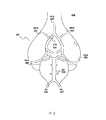
図2は、脳血管系200の主要フィーチャの模式図である。図2中の脳血管系は、脳を下側から見た図であり、ページ上部は、対象者の前部を表す。脳201への血液供給は、頚部を横断する4本の大動脈から送られて来る。より大型の2本の血管として、頚部前部中の右内頚動脈および左内頚動脈(ICA)210がある。椎骨動脈(VA)220は、頚部後部に存在し、合流して脳底動脈(BA)230を形成する。内頚動脈および脳底動脈は、後交通動脈(図示せず)および前交通動脈(図示せず)によって接続されて、ウィリス輪(COW)を形成する。理想的な患者の場合、COWは、接続された動脈からなる網であり、栄養動脈のうち1つ以上が閉塞した場合でも、脳201への血液供給を可能にする。
FIG. 2 is a schematic diagram of the main features of the
脳201へ血液を供給する大動脈として、中央脳動脈(MCA)240、前脳動脈(ACA)250および後脳動脈(PCA)260がある。MCA240は、脳201への一部への血流低下を診断する際に用いられる一領域である。MCA240は、最大の脳領域(すなわち、各脳半球のうちおよそ3分の2)への唯一の血液供給である。
The aorta supplying blood to the
信号経路が一定範囲までMCAs240または他の動脈と合致、横断または交流するように、例示的なヘッドセット120の電極を配置することができる。例えば、電極110をMCA240を跨ぐように配置することで、MCA240が頭部を切断する一対の面間に延び、各電極を通じて延びるようにする。よって、信号特性(例えば、インピーダンス)の測定は、MCA240または他の動脈中の血流を示しかつ/または関連し得る。患者のこめかみまたはその周囲に特定の構成のヘッドセット120を用いて特定の電極110を配置することにより、例えば、特にMCA240中の血流に関連する情報を含む信号の生成が可能になる。上記電極は、例えば70mm〜90mmだけ間隔を空けて配置され得る。上記電極は、頭部上の特定の位置に配置してもよい。例えば、第1の電極対111および112を髪際部の下側の前額部上に配置し、第2の対113および114を耳たぶ上部の下側の耳部上方に配置することができる。これらの位置において、上記電極は、髪の毛の上ではなく素肌上に直接配置することができるため、頭皮の髪の毛が生えている領域上に配置した場合よりも電気接触および接着を向上させることができる。しかし、本発明において、頭皮などの他の位置に電極を配置してもよい。上記電極は、外部顔面動脈および広範囲の筋肉群(例えば、眼筋)から離隔位置に配置してもよい。
The electrodes of the
図3は、対象者の脳201中の例示的な生体インピーダンス信号経路310の模式図である。上記例示的な構成は、右脳半球および左脳半球それぞれを通じた複数の信号経路310を示す。上記複数の信号経路は、ヘッドセット120を介して対象者頭部に固定された電極110の間に延びる。信号経路310のインピーダンスは、上記経路に沿った血液の存在または不在によって影響を受け得る。なぜならば、血液は、相対的に低いインピーダンスを有するからである。信号経路310のうち少なくとも一部は、脳血管系と合致し得る。そのため、血液動態特性(例えば、脳201の血管中の血液量)を示す信号特性を測定することができる。そのため、生体インピーダンスの変化は、脳201中の血流変化を示し得る。図3に示す信号経路310は、信号経路310に一般的領域内に存在し得る少数または限られた数の経路のみを示す。
FIG. 3 is a schematic diagram of an exemplary
本開示によるいくつかの実施形態において、少なくとも1つの頭部生体インピーダンス測定値を特徴付ける前記少なくとも1つの信号は、少なくとも2つの生体インピーダンス信号を含み得る。前記少なくとも2つの生体インピーダンス信号のそれぞれは対象者の脳の異なる脳半球に関する。本明細書において用いられる対象者の脳の特定の脳半球に関する生体インピーダンス信号は、当該のインピーダンス信号が関連する脳の側部のインピーダンス特性を示す生体インピーダンス信号を含み得る。対象者の脳の特定の側部に関する生体インピーダンス信号は、電極などを介して上記対象者の頭部の同一側部から得ることもできるし、あるいは上記対象者の頭部の反対側側部から得ることもできる。対象者の脳の特定の側部に関する生体インピーダンス信号は、他の位置からも得ることができる(例えば、対象者の(例えば頚動脈が存在する)頚部)。 In some embodiments according to the present disclosure, the at least one signal characterizing at least one head bioimpedance measurement may include at least two bioimpedance signals. Each of the at least two bioimpedance signals relates to a different hemisphere of the subject's brain. As used herein, a bioimpedance signal for a particular hemisphere of a subject's brain may include a bioimpedance signal indicative of the impedance characteristics of the side of the brain with which the impedance signal is associated. A bioimpedance signal for a specific side of the subject's brain can be obtained from the same side of the subject's head via an electrode, or from the opposite side of the subject's head. It can also be obtained. A bioimpedance signal for a particular side of the subject's brain can also be obtained from other locations (eg, the subject's neck (eg, the carotid artery is present)).
本開示による実施形態によれば、少なくとも1つの頭部生体インピーダンス測定値を特徴付ける前記少なくとも1つの信号は、対象者の脳の第1の脳半球に関する第1の信号と、対象者の脳の第2の脳半球に関する第2の信号とを含み得る。対象者の脳の第1の脳半球および第2の脳半球に関する第1の生体インピーダンス信号および第2の生体インピーダンス信号の例示的な表現について、図4を参照して説明する。 According to an embodiment according to the present disclosure, the at least one signal characterizing at least one head bioimpedance measurement includes a first signal relating to a first hemisphere of the subject's brain and a first number of the subject's brain. A second signal for two hemispheres. An exemplary representation of the first and second bioimpedance signals for the first and second hemispheres of the subject's brain will be described with reference to FIG.
図4は、装置100等の脳血液動態測定装置から得られた例示的な生体インピーダンス信号401および402の模式図である。図示の生体インピーダンス信号401および402は、比較的健康な患者の右脳半球および左脳半球それぞれのインピーダンス振幅を例示的装置100を用いて測定した際のインピーダンス振幅の周期的変化を示す。このように、信号401および402は、対象者の脳の第1の脳半球および第2の脳半球に関する第1の生体インピーダンス信号および第2の生体インピーダンス信号の例である。
FIG. 4 is a schematic diagram of exemplary bioimpedance signals 401 and 402 obtained from a cerebral hemodynamic measurement device such as
本開示の実施形態により、2つの生体インピーダンス信号は相互に対して同期され得る。本明細書中用いられるように、同期は例えば共通する基準時間フレームについて実行されることができ、前記基準時間フレーム中の信号は、実際に発生したものと比較して、指定時間量を超える差を持たない。例えば、異なるソースから得られた2つの信号は、同一のイベントを同時に反映し得る。しかし、装置、信号処理または他の制約に起因して、これらの信号を記録するための枠となる時間フレームは異なり得る。そのため、前記イベントが第1の信号において1つの時間において発生し、第2の信号において異なる時間において発生したかのように見える場合がある。これらの信号を相互から指定時間量内に同期させることにより、これらの信号は共通する基準時間フレーム内に見られることが可能になる。上記共通する基準時間フレームにおいて、双方の信号によって同時記録されるイベントの発生間の差は、上記第1の信号と上記第2の信号との間における指定時間量を超えない。 According to embodiments of the present disclosure, two bioimpedance signals may be synchronized with respect to each other. As used herein, synchronization can be performed, for example, on a common reference time frame, and the signal in the reference time frame differs by more than a specified amount of time compared to what actually occurred. Does not have. For example, two signals obtained from different sources can reflect the same event simultaneously. However, due to equipment, signal processing or other constraints, the time frame that serves as a frame for recording these signals may be different. Thus, it may appear as if the event occurred at one time in the first signal and at a different time in the second signal. By synchronizing these signals from each other within a specified amount of time, these signals can be found within a common reference time frame. In the common reference time frame, the difference between the occurrences of events recorded simultaneously by both signals does not exceed the specified amount of time between the first signal and the second signal.
同期は、例えば独立したスケール上で発生させてもよいし、あるいは生物スケールに基づいて行ってもよい。生物スケールの一例は、ECGによって規定され得る。詳細には、対向する脳半球の生体インピーダンス波形信号(またはその一部)のタイミングと、ECGによって規定されたスケールとを同期させることができる。一実施形態において、この同期は40ms以内に発生し得る。本発明によれば、より長期の同期方法を用いてもよいし、より短い同期方法を用いてもよい。例えば、信号の相互同期をミリ秒内に行うことができる。タイミング同期の非限定的例を挙げると、約40ms、約30ms、約20ms、約10msおよび約5ms以内の同期がある。他の実施形態において、上記波形を5ms以内に相互に同期させてもよいし、あるいは1ミリ秒の数分の1(例えば、0.1ms以下)以内で同期させてもよい。このような同期分析を生体インピーダンス信号波形の収集時に行い、メモリ(例えば、外部またはコンピュータメモリ)中に保存された生体インピーダンス信号波形上に行うことができる。信号間の相互の同期化は、多様な手段(例えば、タイミング装置および信号内の基準フィーチャ)を通じて行うことが可能である。 The synchronization may occur on an independent scale, for example, or may be performed on a biological scale. An example of a bioscale can be defined by ECG. Specifically, the timing of the bioimpedance waveform signal (or part thereof) of the opposing hemisphere can be synchronized with the scale defined by the ECG. In one embodiment, this synchronization can occur within 40 ms. According to the present invention, a longer synchronization method may be used, or a shorter synchronization method may be used. For example, mutual synchronization of signals can be performed in milliseconds. Non-limiting examples of timing synchronization include synchronization within about 40 ms, about 30 ms, about 20 ms, about 10 ms, and about 5 ms. In other embodiments, the waveforms may be synchronized with each other within 5 ms, or may be synchronized within a fraction of a millisecond (eg, 0.1 ms or less). Such synchronization analysis can be performed at the time of bioimpedance signal waveform collection and can be performed on the bioimpedance signal waveform stored in memory (eg, external or computer memory). Mutual synchronization between signals can be accomplished through a variety of means (eg, timing devices and reference features in the signals).
他の実施形態において、2つの信号は、ECG信号を使用することなく、独立的な時間スケールで同期され得る。右脳半球および左脳半球の波形の同期は、例えば、精密タイミング装置内に設けられた少なくとも1つのプロセッサを用いて行われ得、これにより、双方の脳半球からのデータが同時にまたは既知の時間的関係を以て抽出される。例えば、波形は数ミリ秒内に同期され得、これにより、例えばピーク開始などのフィーチャを関連付けることができる。代替的にまたは装置ベースの同期に加えて、信号の同期を波形中のフィーチャに基づいて行うことができる。心臓電気信号のフィーチャは各脳半球から抽出された波形において共通に検出され得る。例えば、各脳半球からの生体インピーダンス波形に並行して測定されたECG信号から、心拍に先行して発生する電気信号である心臓R波を検出することができる。従って、例えば、ECG波形中のR波開始の検出または同定を用いて、異なる脳半球からの波形を同期させることができる。異なる脳半球からの波形の同期は、例えば心臓周期の任意の他の部分の検出または同定を用いて行うことができる。このような同期分析は、生体インピーダンス信号波形が収集されている間に(例えば、リアルタイムで)行ってもよいし、あるいは、メモリ中に保存された生体インピーダンス信号波形に対して(例えば、非リアルタイムで)行ってもよい。 In other embodiments, the two signals can be synchronized on independent time scales without using an ECG signal. The synchronization of the right and left hemisphere waveforms can be performed, for example, using at least one processor provided in the precision timing device, so that data from both hemispheres can be simultaneously or with a known temporal relationship. Is extracted. For example, the waveforms can be synchronized within a few milliseconds so that features such as peak start can be associated. Alternatively or in addition to device-based synchronization, signal synchronization can be based on features in the waveform. Cardiac electrical signal features can be commonly detected in waveforms extracted from each hemisphere. For example, it is possible to detect a heart R wave, which is an electrical signal generated prior to a heartbeat, from an ECG signal measured in parallel with a bioimpedance waveform from each hemisphere. Thus, for example, the detection or identification of the R wave start in an ECG waveform can be used to synchronize waveforms from different hemispheres. Synchronization of waveforms from different hemispheres can be performed, for example, using detection or identification of any other part of the cardiac cycle. Such synchronous analysis may be performed while the bioimpedance signal waveform is being collected (eg, in real time), or it may be performed on bioimpedance signal waveforms stored in memory (eg, non-real time). In)
右脳半球および左脳半球から受信された信号のフィーチャ間のタイミング遅延を決定することにより、脳血液動態特性についての異なる情報を得ることができる。このようなタイミング遅延は、生体インピーダンス波形全体の間または波形の一部のみの間において発生し得る。例えば、波形の特定フィーチャまたはこれらの様々な組合せについて、遅延を調査することができる。いくつかの実施形態において、遅延が特定の閾値になった場合にのみ、当該遅延が大きいとみなすことができる。一定の条件下において、より大きな遅延は、より小さな遅延と比較して悪化した状態を示し得る。さらに、遅延と共に発生する経時的変化は、状態の改善または悪化を示し得る。いくつかの実施形態において、タイミング遅延の経時的変化を監視することができる。治療期間と共に遅延が低下した場合、患者の脳血管状態が改善していることを示し得、遅延が増加した場合、患者の状態が悪化していることを示し得る。 By determining the timing delay between features of the signals received from the right and left brain hemispheres, different information about cerebral hemodynamic characteristics can be obtained. Such timing delays can occur between the entire bioimpedance waveform or only a portion of the waveform. For example, the delay can be investigated for specific features of the waveform or various combinations thereof. In some embodiments, the delay can be considered large only when the delay reaches a certain threshold. Under certain conditions, a larger delay may indicate a worsening condition compared to a smaller delay. Furthermore, changes over time that occur with delay may indicate an improvement or worsening of the condition. In some embodiments, the change in timing delay over time can be monitored. A decrease in delay with the duration of treatment may indicate that the patient's cerebrovascular condition is improving, and an increase in delay may indicate that the patient's condition is deteriorating.
信号同期により、信号を比較する際における心拍変動に起因する影響も低下させることが可能となる。心拍が変動した場合、心臓周期の長さが変化する。その結果、信号中の対応するフィーチャのタイミングが心拍変動に起因して変動し得る。そのため、非同期波形内のフィーチャのタイミング分析が、心拍変動により影響を受け得る。よって、2つの同期信号間の差を決定することにより、心拍変動による影響を低減することができる。 Signal synchronization can also reduce the effects caused by heart rate variability when comparing signals. When the heartbeat fluctuates, the length of the cardiac cycle changes. As a result, the timing of corresponding features in the signal can vary due to heart rate variability. As such, the timing analysis of features in the asynchronous waveform can be affected by heart rate variability. Therefore, by determining the difference between the two synchronization signals, it is possible to reduce the influence due to heartbeat fluctuation.
本開示のいくつかの実施形態によれば、前記少なくとも1つのプロセッサは、前記少なくとも1つの信号と心臓波とを相関させるようさらに構成され得る。前記少なくとも1つの信号は、信号波形または心臓波形のいずれかの内の任意のフィーチャに基づいて、心臓波形のタイミングに相関され得る。信号を心臓波形のタイミングに相関させることは、信号のフィーチャを心臓波形のフィーチャに関連させることを含み得る。 According to some embodiments of the present disclosure, the at least one processor may be further configured to correlate the at least one signal and a heart wave. The at least one signal may be correlated to the timing of the heart waveform based on any feature within either the signal waveform or the heart waveform. Correlating the signal to the timing of the cardiac waveform may include associating the feature of the signal with the feature of the cardiac waveform.
信号を心臓波形のタイミングに相関させるための例示的な方法については、図4を参照して説明され得る。図4に示すように、生体インピーダンス振幅は、左脳半球および右脳半球双方について周期的サイクルを示し得る。振幅におけるこのような変化の周期は、心臓周期の周期とほぼ同じである。図4において、yスケールは、インピーダンス振幅と逆相関を有する。すなわち、高値のインピーダンス振幅は、図4に示すような信号中の低値によって反映される。より詳細には、各心臓周期はインピーダンス低下と共に開始する。インピーダンス低下は、血流の急激な低下に対応し、図4中の信号ピークとして現れる。図4中の各周期的サイクルの図示の最大値(すなわち、信号ピーク)は、最大血流に対応するインピーダンス最小値を示す。この最大血流は、心室収縮、すなわち血管系を通して血液を押し出す心臓の収縮、に近接して追随し得る。次に、心室収縮は心臓ECGのR波に反映され得る。したがって、心臓R波および生体インピーダンス信号波形の最大値は関連するイベントであり得る。このように、プロセッサはこの関係を認識し、信号と心臓波のタイミングとを相関させるよう構成され得る。信号または心臓波のいずれかの任意の部分が相関のために用いられ得る。 An exemplary method for correlating the signal to the timing of the heart waveform can be described with reference to FIG. As shown in FIG. 4, the bioimpedance amplitude can indicate a periodic cycle for both the left and right hemispheres. The period of such a change in amplitude is approximately the same as the period of the cardiac cycle. In FIG. 4, the y scale has an inverse correlation with the impedance amplitude. That is, the high value impedance amplitude is reflected by the low value in the signal as shown in FIG. More specifically, each cardiac cycle begins with an impedance drop. The impedance drop corresponds to a rapid drop in blood flow and appears as a signal peak in FIG. The illustrated maximum value (ie, signal peak) for each periodic cycle in FIG. 4 indicates the minimum impedance value corresponding to the maximum blood flow. This maximum blood flow can follow closely to the ventricular contraction, the contraction of the heart that pushes blood through the vasculature. The ventricular contraction can then be reflected in the heart ECG R-wave. Therefore, the maximum values of the cardiac R wave and the bioimpedance signal waveform can be related events. In this way, the processor can be configured to recognize this relationship and correlate the signal with the timing of the heart wave. Any portion of either the signal or the heart wave can be used for correlation.
図4において生体インピーダンス信号波形の振幅の変動を示しているが、生体インピーダンス信号波形の位相角から情報を得ることも可能である。生体インピーダンス信号波形の振幅および位相は、対象者の電気インピーダンスの抵抗成分および反応成分双方によって影響され得る。典型的には、対象者の電気インピーダンスの反応成分に起因して、測定された生体インピーダンス信号における位相差が発生し得る。そのため、個別または共に分析された生体インピーダンス信号の振幅および位相は、脳血液動態特性を示し得る。 Although FIG. 4 shows fluctuations in the amplitude of the bioimpedance signal waveform, it is also possible to obtain information from the phase angle of the bioimpedance signal waveform. The amplitude and phase of the bioimpedance signal waveform can be affected by both the resistance component and the reaction component of the subject's electrical impedance. Typically, a phase difference in the measured bioimpedance signal can occur due to the response component of the subject's electrical impedance. As such, the amplitude and phase of the bioimpedance signal, individually or together analyzed, may indicate cerebral hemodynamic characteristics.
信号と心臓波のタイミングとを相関させることは、(代替的に、)前記少なくとも1つの信号の部分と心臓周期に以前に相関された既知の信号とを比較することにより、前記少なくとも1つの信号と心臓周期とのタイミングの一致を検出することも含み得る。この実施形態において心臓周期に以前に相関された既知の信号は、心臓周期内および信号内の様々なフィーチャの関係についての情報を提供し得る。例えば、以前の相関は、心室収縮を表す心臓R波と最大血流を表す生体インピーダンス振幅の最小値との間のタイミング遅延についての情報を提供し得る。新規の生体インピーダンス信号の一部は、新規の生体インピーダンス信号と新規の心臓周期との間の対応するタイミング遅延を検出するために、既知の以前に相関された生体インピーダンス信号の対応する部分と比較され得る。 Correlating the signal with the timing of the heart wave comprises (alternatively) comparing the at least one signal portion by comparing a portion of the at least one signal with a known signal previously correlated with a cardiac cycle. And detecting a timing coincidence with the cardiac cycle. The known signal previously correlated to the cardiac cycle in this embodiment may provide information about the relationship of various features within the cardiac cycle and within the signal. For example, previous correlations may provide information about the timing delay between the cardiac R-wave representing ventricular contraction and the minimum bioimpedance amplitude representing maximum blood flow. A portion of the new bioimpedance signal is compared with a corresponding portion of the known previously correlated bioimpedance signal to detect a corresponding timing delay between the new bioimpedance signal and the new cardiac cycle Can be done.
少なくとも1つの信号と心臓波のタイミングとを相関させることは、さらに(または代替的に)前記少なくとも1つの信号と同時心臓周期のタイミングとを同期することを含み得る。そのような同期は、例えば、前記少なくとも1つの信号が、心臓周期を表す他の信号(例えば、ECG信号)に対する共通の基準時間フレームについて取得されることを確保する測定設備を用いて実行され得る。そのような同期は、前記少なくとも1つの信号と周期を表す他の信号とを分析することによっても、実行され得る。これらの信号は、心臓周期の任意の部分を共通イベントとして用いることにより、同期され得る。この例において、心臓周期の一部は、信号中において同時に検出され得る。その後、信号を、上記心臓周期の当該部分に基づいて同期させることができる。生体インピーダンス測定値を特徴付ける信号と心臓周期との間のタイミング同期の非限定的例を挙げると、約40ms、約30ms、約20ms、約10msおよび約5ms以内の同期がある。他の実施形態において、上記波形を5ms以内に相互に同期させてもよいし、あるいは1ミリ秒の数分の1(例えば、0.1ms以下)以内で同期させてもよい。本開示によるいくつかの実施形態において、信号は、心臓R波に基づいて同期させることができる。 Correlating the at least one signal with the timing of the heart wave may further (or alternatively) include synchronizing the at least one signal with the timing of a simultaneous cardiac cycle. Such synchronization can be performed, for example, using a measurement facility that ensures that the at least one signal is acquired for a common reference time frame relative to other signals representing the cardiac cycle (eg, ECG signals). . Such synchronization can also be performed by analyzing the at least one signal and other signals representing periods. These signals can be synchronized by using any part of the cardiac cycle as a common event. In this example, portions of the cardiac cycle can be detected simultaneously in the signal. The signal can then be synchronized based on that portion of the cardiac cycle. Non-limiting examples of timing synchronization between the signal characterizing the bioimpedance measurement and the cardiac cycle include synchronization within about 40 ms, about 30 ms, about 20 ms, about 10 ms, and about 5 ms. In other embodiments, the waveforms may be synchronized with each other within 5 ms, or may be synchronized within a fraction of a millisecond (eg, 0.1 ms or less). In some embodiments according to the present disclosure, the signals can be synchronized based on cardiac R-waves.
いくつかの実施形態によれば、前記少なくとも1つのプロセッサは、前記心臓波により規定される時間的期間中の少なくとも1つの信号を分析することにより、前記時間的期間中の前記少なくとも1つの信号における少なくとも1つの予想特性の程度を確認するよう構成され得る。 According to some embodiments, the at least one processor analyzes the at least one signal during the time period defined by the heart wave to thereby determine the at least one signal during the time period. It can be configured to ascertain the degree of at least one expected characteristic.
心臓波は、前記少なくとも1つの信号を分析する時間的期間を規定し得る。図5は心臓波を表す例示的なECG信号の模式図である。P波510、Q波511、R波512、S波513、T波514、およびU波515が図5において示される。前述のように、生体インピーダンス信号波形等の信号波形の1周期は、1心臓周期に近似的に対応し得る。したがって、信号は心臓周期のタイミングに相関され得る。P510、Q511、R512、S513、T514、およびU515の波のうちの任意を含む心臓波の任意のフィーチャは、時間的期間を規定するための基準点として用いられ得る。例えば、時間的期間は、第1の心臓周期のR波512のピークと第2の心臓周期のR波512のピークとにより規定され得る。第2の心臓周期は第1の心臓周期に対して連続し得、その場合は図示された例示的な時間的期間516におけるように、時間的期間は1つの心臓周期の長さとなる。第2の心臓周期は第1の心臓周期に対して不連続となり得、その場合は、時間的期間は心臓周期の2倍以上の長さとなる。時間的期間は第1の心臓周期および第2の心臓周期における異なる波(例えば、第1の心臓周期におけるP波および第2の心臓周期におけるR波)によっても規定され得る。時間的期間は、例えば単一の心臓周期内の基準点であるQ波511およびS波513により規定された場合には、単一の心臓周期の長さよりも短くなり得る。分析のための時間的期間は、事前規定されてもよく、または生理学的状態に基づいて動的に規定されてもよい。いくつかの実施形態において、2つ以上の時間的期間が分析のために用いられてもよい。いくつかの実施形態において、2つ以上の信号の部分が時間的期間(単数または複数)中に分析されてもよい。
The heart wave may define a time period during which the at least one signal is analyzed. FIG. 5 is a schematic diagram of an exemplary ECG signal representing a heart wave.
生体インピーダンス信号の予想特性は、検出および分析され得る前記波形内の任意の検出可能なフィーチャを含み得る。予想特性は、プロセッサが検索するよう構成された期待される波形フィーチャも含み得る。予想特性は、波形の視認確認を通じて検出することもできるし、あるいは、波形の数学的分析のみを通じて検出することもできる。予想特性は、波形の単一の局面(例えば、最大振幅)によって規定することもできるし、あるいは、波形の複数の局面(例えば、相対的ピーク高さ)間の関係によって規定することもできる。生体インピーダンス信号波形は、予想特性によって全体的または部分的に特徴付けられ得る。 The expected characteristics of the bioimpedance signal can include any detectable feature in the waveform that can be detected and analyzed. The expected characteristics may also include expected waveform features that the processor is configured to retrieve. The expected characteristic can be detected through visual confirmation of the waveform, or can be detected only through mathematical analysis of the waveform. The expected characteristic can be defined by a single aspect of the waveform (eg, maximum amplitude) or can be defined by the relationship between multiple aspects of the waveform (eg, relative peak height). The bioimpedance signal waveform can be characterized in whole or in part by the expected characteristics.
予想特性の例を挙げると、局所的または全体的な最大値および最小値(すなわち、ピークおよび谷)、変曲点、相対的最大高さ、相対的最小深さ、フィーチャの幅、フィーチャのタイミング、フィーチャの遅延、最大値の高さ・幅の比、最小値の深さ・幅の比、最大値および最小値における曲率、および最大値ならびに最小値の任意の他の局面の比がある。予想特性は、波形の周波数スペクトル局面(例えば、出力スペクトルおよび位相角)をさらに含み得る。他の予想特性は、窓または範囲にわたる平均波形振幅あるいは波形傾斜を含み得る。さらに、多変量分析を用いて、波形のいくつかの最大値、最小値および/または任意の他の局面(例えば、背景振幅、ノイズ、特定の間隔にわたる振幅)を含む予想特性を規定することができる。本明細書中に記載の予想特性はひとえに例示的なものであり、開示の方法およびシステムの任意の実施形態を限定することを意図していない。 Examples of expected characteristics include local or global maximum and minimum values (ie peaks and valleys), inflection points, relative maximum height, relative minimum depth, feature width, feature timing , Feature delay, maximum height / width ratio, minimum depth / width ratio, curvature at maximum and minimum values, and ratio of any other aspect of maximum and minimum values. The expected characteristics may further include the frequency spectrum aspect of the waveform (eg, output spectrum and phase angle). Other expected characteristics may include average waveform amplitude or waveform slope over a window or range. In addition, multivariate analysis can be used to define expected characteristics including some maximum, minimum, and / or any other aspect of the waveform (eg, background amplitude, noise, amplitude over a particular interval) it can. The expected characteristics described herein are exemplary only and are not intended to limit any embodiments of the disclosed methods and systems.
本開示によるいくつかの実施形態において、生体インピーダンス波形の予想特性は、第1のピーク、第2のピーク、第3のピーク、第1の最小値、第2の最小値および第3の最小値のうちの任意を含み得る。本明細書中用いられる第1のピーク、第2のピークおよび第3のピークは、信号波形内の局所的最大値を含み得、第1の最小値、第2の最小値および第3の最小値は、信号波形内の局所的最小値を含み得る。これらのピークおよび最小値は、例えば、サイクル的に反復する波形の単一の期間内の局所的最大値および最小値であり得る。上記ピークおよび最小値はまた、例えば、2つ以上の信号サイクルにわたって平均化された波形内の局所的最大値および最小値を含み得る。ピークおよび最小値はまた、例えば、特定の心拍(例えば、時間間隔内において最も共通する心拍)について決定された波形内の局所的最大値および最小値を含み得る。本明細書において用いられるピークおよび最小値は、絶対的高値および低値に対応する場合もあれば、あるいは、高値および低値が発生した領域を示し得る。例示的な予想特性について、図6を参照してさらに説明する。 In some embodiments according to the present disclosure, the expected characteristic of the bioimpedance waveform includes a first peak, a second peak, a third peak, a first minimum value, a second minimum value, and a third minimum value. May be included. As used herein, the first peak, the second peak, and the third peak may include local maximum values in the signal waveform, the first minimum value, the second minimum value, and the third minimum value. The value may include a local minimum in the signal waveform. These peaks and minimums can be, for example, local maximums and minimums within a single period of a cyclically repeating waveform. The peaks and minimum values may also include, for example, local maximum and minimum values in the waveform averaged over two or more signal cycles. Peaks and minimums may also include, for example, local maximums and minimums in the waveform determined for a particular heartbeat (eg, the most common heartbeat within a time interval). The peaks and minimum values used herein may correspond to absolute high and low values, or may indicate areas where high and low values have occurred. Exemplary expected characteristics are further described with reference to FIG.
図6は、単一の心臓周期により規定される生体インピーダンス信号波形時間的期間610のいくつかの例示的な予想特性の模式図である。波形時間的期間610は心臓周期に対応し、波形中の予想特性は、心臓周期における個々のイベントに対応し得る。例えば、第1のピークP1(611)は、大動脈弁開口に追随する血流の立ち上がりに対応し得る。大動脈弁開口に追随する血流の立ち上がりは、最小値M0(621)に対応し得る。第2のピークP2(612)は、心臓周期の収縮期位相の終了時における血流の第2の立ち上がりに対応し得る。心臓周期の収縮期位相の終了は、最小値M1(622)に対応し得る。最小値M2(623)は、大動脈弁閉鎖時における血流低下に対応し得る。最終ピークP3(613)は、最終血流増加に対応し得る。最終血流増加の後、心臓周期終了時において拡張期位相における連続的低下が発生する。説明目的のみのため、図6に示す予想特性は、生体インピーダンス波形中において検出することが可能な予想特性の一例に過ぎない。さらに、予想特性は、単一の波形期間に閉じ込める必要は無い。例えば異なる期間からの複数の対応する最大値の平均振幅を分析することにより、生体インピーダンス信号の予想特性を決定することができる。 FIG. 6 is a schematic diagram of some exemplary expected characteristics of a bioimpedance signal waveform temporal period 610 defined by a single cardiac cycle. The waveform temporal period 610 corresponds to a cardiac cycle, and the expected characteristics in the waveform can correspond to individual events in the cardiac cycle. For example, the first peak P1 (611) may correspond to a rise in blood flow that follows the aortic valve opening. The rise of the blood flow following the aortic valve opening may correspond to the minimum value M0 (621). The second peak P2 (612) may correspond to a second rise in blood flow at the end of the systolic phase of the cardiac cycle. The end of the systolic phase of the cardiac cycle may correspond to a minimum value M1 (622). The minimum value M2 (623) may correspond to a decrease in blood flow when the aortic valve is closed. The final peak P3 (613) may correspond to a final blood flow increase. After the final blood flow increase, a continuous decrease in the diastolic phase occurs at the end of the cardiac cycle. For illustrative purposes only, the expected characteristics shown in FIG. 6 are merely examples of expected characteristics that can be detected in a bioimpedance waveform. Furthermore, the expected characteristics need not be confined to a single waveform period. For example, the expected characteristics of the bioimpedance signal can be determined by analyzing the average amplitude of a plurality of corresponding maximum values from different time periods.
さらに、図6において振幅によって特徴付けられた生体インピーダンス信号波形を図示しているが、本明細書中に記載の方法および構造は、生体インピーダンス信号波形の他の局面中のシグネチャーフィーチャ(例えば、位相角波形によって特徴付けられるもの)の決定にも用いることが可能である。生体インピーダンス信号の位相角局面は、生体インピーダンス信号の振幅局面と異なる応答を示し得る。なぜならば、位相角変化は、生体インピーダンス信号の反応成分における変化に対応するからである。生体インピーダンス信号波形の位相角局面の分析を行うことにより、血液動態特性についてのさらなる情報または異なる情報を得ることが可能になる。位相角波形の分析は、振幅波形について本明細書中に述べた任意の方法および当該分野において公知の任意のさらなる方法を用いて行うことが可能である。生体インピーダンス信号の位相角波形そのものを分析しかつ/または他の生体インピーダンス信号局面と比較してまたは関連して分析してもよい。 In addition, although the bioimpedance signal waveform characterized by amplitude in FIG. 6 is illustrated, the methods and structures described herein are signature features (eg, phase) in other aspects of the bioimpedance signal waveform. It can also be used to determine (characterized by angular waveforms). The phase angle aspect of the bioimpedance signal may exhibit a response that is different from the amplitude aspect of the bioimpedance signal. This is because the phase angle change corresponds to a change in the reaction component of the bioelectrical impedance signal. By analyzing the phase angle aspect of the bioimpedance signal waveform, it is possible to obtain further or different information about the hemodynamic characteristics. Analysis of the phase angle waveform can be performed using any of the methods described herein for amplitude waveforms and any further methods known in the art. The phase angle waveform of the bioimpedance signal itself may be analyzed and / or analyzed in comparison with or in connection with other bioimpedance signal aspects.
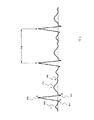
図7aおよび図7bは、複数の心臓周期にわたる生体インピーダンス信号波形の例示的な振幅および位相角局面間の比較の模式図である。図7aに示すような一定の条件下において、位相角波形は、同時入手された振幅波形に類似する特性を示し得る。例えば、図7aにおいて、頭部の左側部(黒色で図示)および右側部(灰色で図示)それぞれからの、位相角波形713と714との間の遅延は、頭部の左側部(黒色で図示)および右側部(灰色で図示)それぞれから得られた振幅波形711および712における遅延に類似する。生体インピーダンス信号波形の位相角局面と振幅局面との間のシグネチャーフィーチャのこのような類似性により、さらなる動脈閉塞の変化を診断するための情報を得ることが可能になる。
7a and 7b are schematic diagrams of comparisons between exemplary amplitude and phase angle aspects of a bioimpedance signal waveform over multiple cardiac cycles. Under certain conditions as shown in FIG. 7a, the phase angle waveform may exhibit characteristics similar to the simultaneously obtained amplitude waveform. For example, in FIG. 7a, the delay between
位相角波形はまた、例えば図7bに示すような同時入手された振幅波形と異なる特性を示し得る。図7bにおいて、頭部の左側部(黒色で図示)および右側部(灰色で図示)それぞれから得られた位相角波形723および724は、頭部の左側部(黒色で図示)および右側部(灰色で図示)それぞれから得られた振幅波形721および722の場合よりも、頭部の左側部および右側部間の非対称性が大幅に大きい。頭部の右側部と関連付けられた位相角波形724のピークは、頭部の右側部と関連付けられた位相角波形723のピークと比較して低下している。さらに、位相角波形723は、ピークからの減衰が急傾斜である。これらの差は、振幅波形721および722において現れない。そのため、生体インピーダンス信号の位相角および振幅波形のシグネチャーフィーチャの差により、動脈閉塞の変化を診断するためのさらなる情報を得ることが可能になる。
The phase angle waveform may also exhibit different characteristics than the co-acquired amplitude waveform, for example as shown in FIG. 7b. In FIG. 7b, the
図6に示すような予想特性は、任意の種類の分析を通じて検出することができる。一実施形態において、測定された波形中の変曲点を発見することにより、予想特性を検出することができる。図8に示す別の実施形態において、パルス分解分析を行うことができる。このような検出分析は、少なくとも1つのプロセッサ(例えば、図1に関連して述べた少なくとも1つのプロセッサ160)を用いて行うことができる。
The expected characteristics as shown in FIG. 6 can be detected through any kind of analysis. In one embodiment, the expected characteristic can be detected by finding an inflection point in the measured waveform. In another embodiment shown in FIG. 8, pulse resolved analysis can be performed. Such detection analysis can be performed using at least one processor (eg, at least one
図8は、生体インピーダンス信号波形期間810の模式図である。生体インピーダンス信号波形期間810は、生体インピーダンス信号中の予想特性を検出するためのパルス分解アルゴリズムによって分解される。図6について説明するように、1組の予想特性は、第1のピークP1611、第2のピークP2612および第3のピークP3613ならびに最小値M0621、最小値M1622および最小値M2623を含み得る。最小値M0621、最小値M1622および最小値M2623は、図6に示すように、生体インピーダンス信号波形611における変曲点に基づいて計算することができる。パルス分解アルゴリズムは、予想特性を計算するための別の方法を示す。パルス分解アルゴリズムは、生体インピーダンス信号を概算するための基本関数の組み合わせを用いて、生体インピーダンス信号をパラメータ化し得る。
FIG. 8 is a schematic diagram of the bioelectrical impedance
最良の適合のために用いられる基本関数は、生理学的パルス波形関数に関連し得るか、または、生理学的パルスに類似する一般的形状を持ち得かつ安定した適合パラメータを提供する。適切な基本関数の一例として、ガウス関数がある。ガウス基本関数により、パルス幅および曲率、安定した適合アルゴリズム、および高次導関数の全体的決定を明確に定義することが可能になる。ガウス基本関数を用いたパルス分解アルゴリズムは、図8を参照して以下に説明するように行うことができる。 The basic function used for best fit may be related to a physiological pulse waveform function or may have a general shape similar to a physiological pulse and provide a stable fit parameter. An example of a suitable basic function is a Gaussian function. Gaussian basic functions allow for a clear definition of pulse width and curvature, stable fitting algorithm, and overall determination of higher order derivatives. The pulse decomposition algorithm using the Gaussian basic function can be performed as described below with reference to FIG.
図8は、3つのガウス基本関数(第2のピークP2612、第1のピークP1611および第3のピークP3613にそれぞれ最適に適合するように計算された第1のガウス821、第2のガウス822、および第3のガウス823)の模式図である。ECG信号を用いて、生体インピーダンス信号を、心臓周期にそれぞれ対応する個々の波形810に分割することができる。その後、ECGR波パルスに追随する波形最小値を決定することができる。次に、最小値に追随する波形全体的最大点を決定することができる。その後、全体的最大点と前回入手された統計との間のタイミング間の対応に基づいて、上記波形全体的最大点が第1のピークP1611、第2のピークP2612、または第3のピークP3613を示すかを決定することができる。次に、標準的基本関数(例えば、ガウス)を用いて、前回得られた統計からのタイミングおよび幅限定を用いて、決定された全体的最大の近隣の個々の波形への最適な適合を得ることができる。図8において、第1のガウス821を最高ピークP2612に適合させる。次に、残りの波形に対して同じ基本関数を用いて、第2のガウス822および第3のガウス823を用いた残りの2つのピークの最適適合を決定することができる。
FIG. 8 shows three Gaussian basic functions (a first Gaussian 821, a
これらのガウス基本関数は、生体インピーダンス信号波形を近似する予想特性適合曲線820を協働して形成する。例示的なパルス分解アルゴリズムから得られた予想特性適合曲線820のコンポーネント基本関数を規定するパラメータは、測定された生体インピーダンス信号中の各心臓周期を特徴付けるように機能し得る。
These Gaussian fundamental functions cooperate to form an expected characteristic
その後、上記測定された信号と、各心臓周期の予想特性適合曲線820を含む平滑な波形とを置換する。その結果、多様な対象点(例えば、最小値M0621、最小値M1622、最小値M2623、および対象点における局所的曲率)のロバストな計算が可能になる。コンピュータパラメータ、相対的振幅、タイミング対ECG、および幅を用いて、波形を特徴付けることができる。開示の例示的なパルス分解アルゴリズムなどの方法は、他の技術(例えば、変曲点決定)を用いて検出することが困難または不可能な予想特性を検出する際に有用である。図8に示すように、ピークP1611、ピークP2612およびピークP3613は、生体インピーダンス信号波形610の局所的最大値と合致しないが、生体インピーダンス信号波形610の成分波形、ガウス821、822および823のピークとは合致する。
Thereafter, the measured signal is replaced with a smooth waveform including the expected characteristic
さらなる例示的な基本関数を挙げると、一般化極値(GEV)分布関数がある。GEV関数は、他の基本関数(例えば、ガウス)と共に用いてもよいし、あるいは単独の基本関数として用いてもよい。例えば、周期的生体インピーダンス信号を分解する場合、ガウス基本関数を用いて、波形の収縮期部分中の第1のピークP1611および第2のピークP2612と、拡張期部分上のP3613のGEV関数とを適合させることができる。この選択により、P3613に対してガウス基本関数を用いる場合よりも、上記拡張期部分に対してより良好な適合が得られる。なぜならば、GEV関数は非対称であり得る一方、ガウス関数は対称であるからである。 A further exemplary basic function is the generalized extreme value (GEV) distribution function. The GEV function may be used together with other basic functions (for example, Gaussian) or may be used as a single basic function. For example, when decomposing a periodic bioimpedance signal, the Gaussian basic function is used to calculate the first peak P1611 and the second peak P2612 in the systolic part of the waveform and the GEV function of P3613 on the diastolic part. Can be adapted. This selection provides a better fit for the diastolic part than when using Gaussian fundamental functions for P3613. This is because the GEV function can be asymmetric while the Gaussian function is symmetric.
生体インピーダンス信号波形のパラメータ化を行うことにより、さらなる予想特性(例えば、初期パラメータの分布統計)の収集および比較も可能になる。例えば、脳卒中患者の1つの脳半球上において測定されたP2612パルスタイミングの分布は、予想特性を示し得、第2の脳半球から得られたP2612パルスタイミングの分布によって示される予想特性と比較され得る。 By parameterizing the bioimpedance signal waveform, it is also possible to collect and compare additional predictive properties (eg, initial parameter distribution statistics). For example, the distribution of P2612 pulse timing measured on one brain hemisphere of a stroke patient can exhibit expected characteristics and can be compared to the expected characteristics indicated by the distribution of P2612 pulse timing obtained from the second hemisphere. .
いくつかの実施形態において、信号を分析することは、少なくとも1つの信号を、少なくとも1つの予想特性と前記信号との間の相関程度とに基づく予測に適合させることを含み得る。例えば上述のように予想特性の分析を用いることにより、将来の信号波形についての予測が可能となる。すなわち、不在の生理学的変化、生体インピーダンス信号波形が、例えば、将来における同様の予想特性を示すと予測され得る。そのような予測からの逸脱は脳血管イベント等の生理学的変化を示し得る。 In some embodiments, analyzing the signal may include adapting the at least one signal to a prediction based on at least one prediction characteristic and a degree of correlation between the signals. For example, the prediction of the future signal waveform can be performed by using the prediction characteristic analysis as described above. That is, absent physiological changes, bioimpedance signal waveforms, for example, can be predicted to exhibit similar expected characteristics in the future. Deviations from such predictions may indicate physiological changes such as cerebrovascular events.
図6に示すような生体インピーダンス信号の予想特性を分析することにより、生理学的脳状態における変化(例えば、脳血流における変化)を予測するための情報を得ることができる。予想特性を経時的に連続的に分析および比較することにより、診断情報を得ることができる。例えば、生体インピーダンス信号波形データを連続的にサンプリングして、連続する時間間隔内の各心臓周期に対する予想特性を計算することができる。上記連続的時間間隔の一部の監視から得られた結果と、上記連続的時間間隔の別の一部の監視から得られた結果とを比較することができる。例えば、外科手術時に発生する任意の脳血流変化を診断するために患者に対して行われる外科手術時において、予想特性を連続的時間間隔全体にわたって連続的に監視することができる。上記外科手術時における任意の長さの任意の1つの時間間隔において検出された予想特性と、上記外科手術時における任意の長さの任意の後続の時間間隔において検出された予想特性とを比較することができる。 By analyzing the predicted characteristic of the bioelectrical impedance signal as shown in FIG. 6, information for predicting a change in a physiological brain state (for example, a change in cerebral blood flow) can be obtained. Diagnostic information can be obtained by continuously analyzing and comparing the expected characteristics over time. For example, bioimpedance signal waveform data can be sampled continuously to calculate the expected characteristics for each cardiac cycle within successive time intervals. The results obtained from monitoring one part of the continuous time interval can be compared with the results obtained from monitoring another part of the continuous time interval. For example, during a surgical procedure performed on a patient to diagnose any cerebral blood flow change that occurs during the surgical procedure, the expected characteristics can be continuously monitored over a continuous time interval. Comparing expected characteristics detected at any one time interval of any length at the time of surgery with expected characteristics detected at any subsequent time interval of any length at the time of surgery be able to.
代替的にまたは追加的に、非連続的時間期間にわたって予想特性を監視および予測に対して比較して、診断情報を得ることができる。例えば、1つの時間間隔時において監視された生体インピーダンス信号波形データと、第2の時間間隔時において監視された生体インピーダンス信号波形データとを比較することができる。第2の時間間隔は、第1の時間間隔と重複または隣接しない。例えば、患者についての予想特性基線を第1の時間(例えば、外科手術の前、入院時、定期的来院時、または基線測定が可能な任意の他の時間)に測定することができる。その後、上記予想特性基線と、任意の後続時間(例えば、外科手術時、退院時、別の来院時)において監視された予想特性とを比較することができる。 Alternatively or additionally, the expected characteristics can be compared against monitoring and prediction over non-continuous time periods to obtain diagnostic information. For example, bioimpedance signal waveform data monitored at one time interval can be compared with bioimpedance signal waveform data monitored at a second time interval. The second time interval does not overlap or are adjacent to the first time interval. For example, an expected characteristic baseline for a patient can be measured at a first time (eg, before surgery, at admission, at a regular visit, or any other time that allows baseline measurements). The expected characteristic baseline can then be compared to the expected characteristic monitored at any subsequent time (eg, at the time of surgery, at discharge, at another visit).
いくつかの実施形態において、分析することは、表示された生理学的状態に基づいて、予想特性付近の時間的期間に注目することを含み得る。分析が生理学的状態(例えば、動脈閉塞または脳水腫等)を示す場合、その生理学的状態に関連付けられ得る特定の予想特性付近の時間的期間がより詳細に分析され得る。そのような詳細な分析により、その生理学的状態についての追加的な情報が得られ得る。例えば、MCAにおける閉塞についてのさらなる情報が、第2のピークP2612をより詳細に分析することから得られ得る。 In some embodiments, analyzing may include focusing on a time period near an expected characteristic based on the displayed physiological state. If the analysis indicates a physiological condition (eg, arterial occlusion or cerebral edema), the time period near a particular expected characteristic that can be associated with that physiological condition can be analyzed in more detail. Such detailed analysis can provide additional information about the physiological state. For example, further information about the occlusion in the MCA can be obtained from analyzing the second peak P2612 in more detail.
本開示によれば、少なくとも1つのプロセッサは、少なくとも1つの信号における少なくとも1つの予想特性の程度に基づいて、生理学的脳状態を予測するための情報を出力するよう構成され得る。本明細書中用いられる「生理学的脳状態を予測するための情報」は、医師による生理学的脳状態の検出、診断、理解、または予測を支援し得る任意の種類の情報を含み得る。このような情報は、例えば、生理学的脳状態の直接的通知を含み得、あるいは、生理学的脳状態の診断を支援する情報を含み得る。生理学的脳状態を予測するための情報は、状態の位置および程度についての特定の情報を含む場合もあるし、あるいは、状態における変化を示す一般的情報を含み得る。例えば、前述のように、患者頭部の対向する側部からの生体インピーダンス関連測定/計算の非対称性は、診断目的のために出力される情報であり得る。一実施形態において、非対称性の存在は、唯一の情報出力であり得る。別の実施形態において、非対称性の測定値が上記情報出力中に含まれ得る。さらに別の実施形態において、情報出力は、非対称性の経時的変化の指標を含み得る。 According to the present disclosure, the at least one processor may be configured to output information for predicting a physiological brain state based on the degree of at least one expected characteristic in the at least one signal. As used herein, “information for predicting a physiological brain condition” may include any type of information that can assist a physician in detecting, diagnosing, understanding, or predicting a physiological brain condition. Such information may include, for example, direct notification of a physiological brain condition, or may include information that assists in the diagnosis of the physiological brain condition. Information for predicting a physiological brain state may include specific information about the location and extent of the state, or it may include general information indicating changes in the state. For example, as described above, bioimpedance-related measurement / calculation asymmetry from opposite sides of the patient's head can be information output for diagnostic purposes. In one embodiment, the presence of asymmetry may be the only information output. In another embodiment, asymmetry measurements may be included in the information output. In yet another embodiment, the information output may include an indication of the asymmetry change over time.
上記出力情報は、大幅な変動の存在を示す簡単な指標として医療専門家に対して用いることが可能である。代替的にまたは追加的に、上記出力情報を挙げると、例えば、差異の大きさと、差異の経時的変化の大きさと、生理学的脳状態、生理学的脳状態の程度、または生理学的脳状態の程度における変化を示し得る他の任意のデータと、のうちの1つ以上がある。 The output information can be used for medical professionals as a simple index indicating the presence of significant fluctuations. Alternatively or additionally, the output information may include, for example, the magnitude of the difference, the magnitude of the difference over time, the physiological brain state, the degree of the physiological brain state, or the degree of the physiological brain state There are one or more of any other data that may indicate a change in.
生理学的脳状態を予測するための情報は、虚血性脳卒中の存在を診断するための情報を含み得る。動脈閉塞が変化した場合、脳の一部が動脈閉塞に起因して適切な血液供給を受容できなくなっている脳状態である虚血性脳卒中に繋がり得る。いくつかの実施形態において、プロセッサは、虚血性脳卒中の存在に基づいて、出血性脳卒中の不在を診断するように構成され得る。出血性脳卒中は、脳内出血に起因して脳が適切な血液供給を受容できなくなっている脳状態である。虚血性および出血性脳卒中の表だった兆候は、類似し得る。対象者体内の虚血性脳卒中の存在は、脳卒中の表だった兆候を示し、出血性脳卒中の不在を示し得る。 Information for predicting a physiological brain state may include information for diagnosing the presence of an ischemic stroke. If arterial occlusion changes, it can lead to ischemic stroke, a brain condition in which part of the brain is unable to accept an adequate blood supply due to arterial occlusion. In some embodiments, the processor may be configured to diagnose the absence of hemorrhagic stroke based on the presence of ischemic stroke. A hemorrhagic stroke is a brain condition in which the brain cannot accept an adequate blood supply due to intracerebral hemorrhage. The signs that were tabular for ischemic and hemorrhagic stroke may be similar. The presence of an ischemic stroke in the subject's body indicates signs that were a manifestation of a stroke and may indicate the absence of a hemorrhagic stroke.
生理学的脳状態を予測するための情報は、少なくとも1つの予想特性の程度に基づき得る。上述したように、対象者頭部から得られた生体インピーダンス信号波形は、脳血流を示し得る。そのため、生体インピーダンス信号波形内の予想特性の程度は、脳血流を示し得、予想特性の程度における変化は、脳血流における変化を示し得る。脳血流における変化を分析することにより、生理学的脳状態を予測するための情報が得られ得る。例えば、インピーダンス最小値に対応する各期間における局所的最大値の高さが第1の時間的期間と第2の時間的期間との間において低下した場合、脳血流の低下を示し得る。 Information for predicting a physiological brain state may be based on a degree of at least one expected characteristic. As described above, the bioelectrical impedance signal waveform obtained from the subject's head can indicate cerebral blood flow. Therefore, the degree of expected characteristics in the bioimpedance signal waveform may indicate cerebral blood flow, and a change in the degree of expected characteristics may indicate a change in cerebral blood flow. By analyzing changes in cerebral blood flow, information for predicting a physiological brain state can be obtained. For example, a decrease in cerebral blood flow may be indicated if the local maximum height in each period corresponding to the impedance minimum value decreases between a first time period and a second time period.
いくつかの実施形態において、前記プロセッサは、対象者の脳の第1の脳半球に関する第1の信号の部分と対象者の脳の第2の脳半球に関する第2の信号の部分との比較に少なくとも部分的に基づいて、生理学的脳状態を予測するよう構成される。第1の信号の部分と第2の信号の部分とを比較することは、これらの信号に対して行われる任意の種類の分析を含み得る。これらの信号は、基本的算術演算(例えば、加算、減算、その他)を用いて比較され得る。これらの信号は時間領域において比較され得る。これらの信号は、適切な変換を用いることにより、周波数領域においても比較され得る。1つの信号の全体または一部は、別の信号の全体または一部と比較され得る。例えば、これらの信号は、より小さな区画により、および/または別個の点により、その全体において比較され得る。代替的に(または追加的に)、1つ以上の信号の一部は、1つ以上の他の信号の対応する部分または対応しない部分と比較され得る。さらに、これらの信号は、任意の長さの時間間隔において測定された振幅、周波数および位相角に基づいて比較され得る。これらの信号は、信号の予想特性にも基づいて比較され得る。 In some embodiments, the processor compares the portion of the first signal for the first hemisphere of the subject's brain with the portion of the second signal for the second hemisphere of the subject's brain. Based at least in part, configured to predict a physiological brain state. Comparing the first signal portion and the second signal portion may include any type of analysis performed on these signals. These signals can be compared using basic arithmetic operations (eg, addition, subtraction, etc.). These signals can be compared in the time domain. These signals can also be compared in the frequency domain by using appropriate transforms. All or part of one signal may be compared to all or part of another signal. For example, these signals can be compared in their entirety by smaller sections and / or by discrete points. Alternatively (or additionally), one or more signal portions may be compared to corresponding or non-corresponding portions of one or more other signals. Furthermore, these signals can be compared based on measured amplitude, frequency, and phase angle in any length of time interval. These signals can be compared based on the expected characteristics of the signals.
この比較は、対象者の脳の異なる脳半球に関連する第1の信号と第2の信号との間の比較であり得る。脳の対向する側部から得られた生体インピーダンス信号は、対向する脳半球中の血流を反映する。脳卒中は典型的には非対称の現象であるため、異なる脳半球から得られた信号の予想特性を比較することにより、脳卒中による影響を受けた脳側部についての情報を得ることができる。2つの脳半球からの生体インピーダンス信号波形(例えば、図4に示すような)を相互に比較することにより、生理学的脳状態を予測することができる。脳血管イベントを示している患者において、例えば上記2つの生体インピーダンス信号波形は、図4に示す健康な患者の場合よりもより高レベルの相違点を示す場合が多い。 This comparison may be a comparison between a first signal and a second signal associated with different hemispheres of the subject's brain. The bioimpedance signal obtained from the opposing sides of the brain reflects the blood flow in the opposing hemisphere. Because stroke is typically an asymmetric phenomenon, information about the side of the brain affected by the stroke can be obtained by comparing the expected characteristics of signals obtained from different hemispheres. By comparing bioimpedance signal waveforms from two hemispheres (eg, as shown in FIG. 4) with each other, a physiological brain state can be predicted. In patients exhibiting a cerebrovascular event, for example, the two bioimpedance signal waveforms often show a higher level of difference than in the healthy patient shown in FIG.
例えば図9に示す信号において、破線によって示す左脳半球生体インピーダンス信号912は、右脳半球生体インピーダンス信号911と比較して、インピーダンス振幅における変化は顕著に低下している。加えて、左脳半球生体インピーダンス信号912において、ピークP2612は完全に消失したように見受けられ、残りのピークP1611は、右脳半球生体インピーダンス信号911の対応するピークと比較して、タイミング遅延を示す。低下したインピーダンス振幅およびタイミング遅延の双方は脳卒中を反映し得る。左脳半球から得られた生体インピーダンス信号と左脳半球から得られた生体インピーダンス信号とを比較することにより、生理学的脳状態を予測するための情報が得られ得る。
For example, in the signal shown in FIG. 9, the change in the impedance amplitude of the left hemisphere bioimpedance signal 912 indicated by a broken line is significantly lower than that of the right brain hemisphere bioimpedance signal 911. In addition, in the left hemisphere bioimpedance signal 912, the peak P2612 appears to have disappeared completely, and the remaining peak P1611 shows a timing delay compared to the corresponding peak of the right
本開示の他の実施形態によれば、前記プロセッサは、前記少なくとも1つの信号におけるフィーチャを脳血流画像情報で較正するよう構成され得る。脳血流画像情報は、脳血流に関する任意の種類の画像情報を含み得る。そのような情報は、脳血流画像(例えば、実際の画像)を直接的に構成する情報を含み得、脳血流画像を記述する情報(例えば、画像から得られた血流の測定値)を含み得る。脳血流画像情報は、脳血流画像を分析するタスクを実行するコンピュータ等により自動的に生成され得る。そのような情報は、例えば医師が脳血流画像に基づいて診断を行うことにより、手動によっても生成され得る。任意の好適なソース(例えば、磁気共鳴映像法(MRI)、経頭蓋ドップラー超音波法(TCD)またはかん流コンピュータ断層撮影(PCT)および血管造影(CTA))が、脳血流情報を提供し得る。 According to other embodiments of the present disclosure, the processor may be configured to calibrate features in the at least one signal with cerebral blood flow image information. The cerebral blood flow image information may include any type of image information related to cerebral blood flow. Such information may include information that directly constitutes a cerebral blood flow image (eg, an actual image), and information that describes the cerebral blood flow image (eg, a blood flow measurement obtained from the image). Can be included. The cerebral blood flow image information can be automatically generated by a computer or the like that executes a task of analyzing the cerebral blood flow image. Such information can also be generated manually, for example, by a doctor making a diagnosis based on a cerebral blood flow image. Any suitable source (eg, magnetic resonance imaging (MRI), transcranial Doppler ultrasound (TCD) or perfusion computed tomography (PCT) and angiography (CTA)) provides cerebral blood flow information. obtain.
プロセッサにより受診された信号のフィーチャは、脳血流情報に対応するよう、較正され得る。生体インピーダンス信号のフィーチャは、そのフィーチャに対応する脳血液情報に比較され、そのような脳血液情報に相関付けられ得る。次に、このような比較および相関付けを、生体インピーダンス信号測定からのデータの解釈、定量化およびモデリングにおいて用いることができる。例えば、主要脳血管(例えば、中央脳動脈(MCA)240)中の閉塞をMRI技術およびCTA技術を通じて確認した場合、脳201の当該部分における血流が遅延または低下がみられる。そのような閉塞を経験する対象者から得られた生体インピーダンス信号波形は、閉塞に一致する信号フィーチャを示し得る。これらのフィーチャは、遅延された血流または減少された血流を詳述する直接的脳血流画像情報で較正され得る。
The features of the signal received by the processor can be calibrated to correspond to cerebral blood flow information. A feature of the bioimpedance signal may be compared to and correlated with cerebral blood information corresponding to the feature. Such comparison and correlation can then be used in the interpretation, quantification and modeling of data from bioimpedance signal measurements. For example, when an obstruction in a major cerebral blood vessel (eg, central cerebral artery (MCA) 240) is confirmed through MRI and CTA techniques, blood flow in that portion of the
上記の説明は、信号波形の受信、相関、および分析を行うためのいくつかの例示的な方法を説明するものである。しかし、別の実施形態により、これらのタスクを実行するための他の方法を用いることも可能である。例えば、いくつかの実施形態において、ピークP1511、P2512およびP3513以外の予想特性を用いることができる。いくつかの実施形態において、予想特性検出のための別のパルス分解方法が用いられ得る。いくつかの実施形態において、予想特性検出のための別の方法が用いられ得る。よって、当業者であれば、予想特性の程度に基づいて信号を分析するための多様な分析技術が存在しており、本発明はその最大の範囲において任意の特定の技術に限定されないことを理解するであろう。 The above description describes several exemplary methods for receiving, correlating, and analyzing signal waveforms. However, other methods for performing these tasks may be used according to alternative embodiments. For example, in some embodiments, expected characteristics other than peaks P1511, P2512 and P3513 can be used. In some embodiments, another pulse decomposition method for predictive property detection may be used. In some embodiments, another method for predictive property detection may be used. Thus, those skilled in the art will understand that there are a variety of analysis techniques for analyzing signals based on the degree of expected characteristics, and that the present invention is not limited to any particular technique in its maximum scope. Will do.
本開示による実施形態において、生理学的脳状態を予測するための方法が提供される。図10は、生理学的脳状態を予測するための例示的方法のステップのフローチャートである。ステップ1001において、少なくとも1つの頭部生体インピーダンス測定値を特徴付ける少なくとも1つの信号が受信され得る。これらの信号は、例えば、適切に構成されたプロセッサ160によって受信され得る。ステップ1002において、前記少なくとも1つの信号は、心臓波形のタイミングに相関され得る。プロセッサ160はこのステップを実行するよう構成され得る。
In an embodiment according to the present disclosure, a method for predicting a physiological brain state is provided. FIG. 10 is a flowchart of steps of an exemplary method for predicting a physiological brain state. In
ステップ1003において、前記少なくとも1つの信号を分析することにより、前記信号における少なくとも1つの特性の程度が確認され得る。前記少なくとも1つの信号は心臓波により規定される時間的期間中に分析され、好適に構成されたプロセッサ160により分析され得る。ステップ1004において、分析ステップ1003の結果を用いて、前記少なくとも1つの信号における前記少なくとも1つの予想特性の程度に基づいて生理学的脳状態を予測するための情報が出力され得る。プロセッサ160は、例えば、上記情報を出力するように構成され得る。生理学的脳状態を予測するためのさらなる方法を挙げると、本明細書中に開示される技術のうちいずれかおよび/または全てがある。
In
上記例のうち多くについて、右脳半球と左脳半球との比較を挙げて説明してきたが、対象者の頭部の多様な位置から測定および比較が可能であり、本発明はその最大の範囲において比較信号を対向する脳半球に限定しなくてもよいことが理解される。同様に、本開示において生体インピーダンス信号の分析の例について記載しているが、本開示の広い原理に基づいて、少なくとも1つの頭部生体インピーダンス測定値を特徴付ける任意の信号を評価することが可能である。 Although many of the above examples have been described by comparing the right and left brain hemispheres, it can be measured and compared from various positions of the subject's head, and the present invention compares in the maximum range. It will be appreciated that the signal need not be limited to the opposing hemisphere. Similarly, although an example of bioimpedance signal analysis is described in this disclosure, any signal characterizing at least one head bioimpedance measurement can be evaluated based on the broad principles of this disclosure. is there.
さらに、脳卒中および閉塞の検出、診断および監視のための本発明の実施形態の利用の開示はひとえに例示的なものである。本発明は、その最大の範囲において、本明細書中に記載の原理を用いて検出することが可能な任意の生理学的脳状態の検出、診断および/または治療に関連して用いることが可能である。さらに、対象者の脳中の動脈閉塞の変化を診断するための本明細書中に記載の方法および装置を一般化することにより、任意の発生の動脈閉塞(例えば、脳卒中、血管変性)の変化を診断することが可能になることが理解される。本発明に関連する分野の当業者であれば、本発明の意図および範囲から逸脱することなく、別の実施形態を想起する。よって、本発明の範囲は、上記の記載によってではなく、添付の特許請求の範囲によって定義される。 Further, the disclosure of the use of embodiments of the present invention for detecting, diagnosing and monitoring stroke and occlusion is exemplary only. The present invention, to its greatest extent, can be used in connection with the detection, diagnosis and / or treatment of any physiological brain condition that can be detected using the principles described herein. is there. Furthermore, any generalized arterial occlusion (eg, stroke, vascular degeneration) changes by generalizing the methods and apparatus described herein for diagnosing changes in arterial occlusions in a subject's brain It will be understood that it becomes possible to diagnose. Those skilled in the art to which the present invention pertains will contemplate other embodiments without departing from the spirit and scope of the present invention. Accordingly, the scope of the invention will be defined by the attached claims not by the above description.
Claims (30)
少なくとも1つのプロセッサであって、前記少なくとも1つのプロセッサは、
少なくとも1つの頭部生体インピーダンス測定値を特徴付ける少なくとも1つの信号を受信する、ことと、
前記少なくとも1つの信号と心臓波のタイミングとを相関させる、ことと、
前記心臓波により規定される時間的期間中の前記少なくとも1つの信号を分析することにより、前記時間的期間中における前記少なくとも1つの信号における少なくとも1つの予想特性の程度を確認する、ことと、
前記少なくとも1つの信号における前記少なくとも1つの予想特性の前記程度に基づいて生理学的脳状態を予測するための情報を出力する、ことと、
を行うよう構成される、プロセッサ、
を含む、脳血液動態測定装置。 A cerebral hemodynamic measurement device,
At least one processor, wherein the at least one processor is:
Receiving at least one signal characterizing at least one head bioimpedance measurement;
Correlating the at least one signal with cardiac timing;
Determining the degree of at least one expected characteristic in the at least one signal during the time period by analyzing the at least one signal during the time period defined by the heart wave;
Outputting information for predicting a physiological brain state based on the degree of the at least one expected characteristic in the at least one signal;
Configured to do the processor,
A cerebral hemodynamic measurement device.
少なくとも1つの頭部生体インピーダンス測定値を特徴付ける少なくとも1つの信号を受信することと、
前記少なくとも1つの信号と心臓波のタイミングとを相関させることと、
前記心臓波により規定される時間的期間中の前記少なくとも1つの信号を分析することにより、前記時間的期間中の前記少なくとも1つの信号における少なくとも1つの予想特性の程度を確認することと、
前記少なくとも1つの信号における前記少なくとも1つの予想特性の前記程度に基づいて生理学的脳状態を予測するための情報を出力することと、
を含む、方法。 A method for predicting a physiological brain state, comprising:
Receiving at least one signal characterizing at least one head bioimpedance measurement;
Correlating the at least one signal with a cardiac wave timing;
Ascertaining the degree of at least one expected characteristic in the at least one signal during the time period by analyzing the at least one signal during the time period defined by the heart wave;
Outputting information for predicting a physiological brain state based on the degree of the at least one expected characteristic in the at least one signal;
Including a method.
Applications Claiming Priority (7)
| Application Number | Priority Date | Filing Date | Title |
|---|---|---|---|
| US201161441248P | 2011-02-09 | 2011-02-09 | |
| US61/441,248 | 2011-02-09 | ||
| US201161474739P | 2011-04-12 | 2011-04-12 | |
| US61/474,739 | 2011-04-12 | ||
| US13/252,191 US9307918B2 (en) | 2011-02-09 | 2011-10-03 | Devices and methods for monitoring cerebral hemodynamic conditions |
| US13/252,191 | 2011-10-03 | ||
| PCT/IB2012/000846 WO2012107843A2 (en) | 2011-02-09 | 2012-02-08 | Devices and methods for monitoring cerebral hemodynamic conditions |
Publications (2)
| Publication Number | Publication Date |
|---|---|
| JP2014507992A true JP2014507992A (en) | 2014-04-03 |
| JP2014507992A5 JP2014507992A5 (en) | 2015-03-26 |
Family
ID=46601098
Family Applications (4)
| Application Number | Title | Priority Date | Filing Date |
|---|---|---|---|
| JP2013553046A Expired - Fee Related JP5981945B2 (en) | 2011-02-09 | 2012-02-07 | Device and method for monitoring cerebral hemodynamic status |
| JP2013553045A Expired - Fee Related JP5981944B2 (en) | 2011-02-09 | 2012-02-07 | Device and method for monitoring cerebral hemodynamic status |
| JP2013553048A Pending JP2014507992A (en) | 2011-02-09 | 2012-02-08 | Apparatus and method for monitoring cerebral hemodynamic status |
| JP2013553047A Pending JP2014516593A (en) | 2011-02-09 | 2012-02-08 | Device and method for monitoring cerebral hemodynamic characteristics |
Family Applications Before (2)
| Application Number | Title | Priority Date | Filing Date |
|---|---|---|---|
| JP2013553046A Expired - Fee Related JP5981945B2 (en) | 2011-02-09 | 2012-02-07 | Device and method for monitoring cerebral hemodynamic status |
| JP2013553045A Expired - Fee Related JP5981944B2 (en) | 2011-02-09 | 2012-02-07 | Device and method for monitoring cerebral hemodynamic status |
Family Applications After (1)
| Application Number | Title | Priority Date | Filing Date |
|---|---|---|---|
| JP2013553047A Pending JP2014516593A (en) | 2011-02-09 | 2012-02-08 | Device and method for monitoring cerebral hemodynamic characteristics |
Country Status (5)
| Country | Link |
|---|---|
| US (4) | US9345411B2 (en) |
| EP (4) | EP2672886A2 (en) |
| JP (4) | JP5981945B2 (en) |
| CN (4) | CN104023623A (en) |
| WO (4) | WO2012107836A2 (en) |
Families Citing this family (44)
| Publication number | Priority date | Publication date | Assignee | Title |
|---|---|---|---|---|
| US9345411B2 (en) | 2011-02-09 | 2016-05-24 | Orsan Medical Technologies, Ltd. | Devices and methods for monitoring cerebral hemodynamic conditions |
| US9456757B1 (en) * | 2011-10-03 | 2016-10-04 | Yi Zheng | Noninvasive monitoring hydrocephalus, cerebral edema, and intracranial bleeding using electromagnetic wave propagation properties |
| US8870783B2 (en) * | 2011-11-30 | 2014-10-28 | Covidien Lp | Pulse rate determination using Gaussian kernel smoothing of multiple inter-fiducial pulse periods |
| US10743815B2 (en) | 2012-01-19 | 2020-08-18 | Cerebrotech Medical Systems, Inc. | Detection and analysis of spatially varying fluid levels using magnetic signals |
| US11357417B2 (en) | 2012-01-19 | 2022-06-14 | Cerebrotech Medical Systems, Inc. | Continuous autoregulation system |
| AU2013209519B2 (en) | 2012-01-19 | 2017-05-25 | Cerebrotech Medical Systems, Inc. | Diagnostic system for detection of fluid changes |
| CN103654760B (en) * | 2012-09-10 | 2016-08-03 | 焦文华 | Noninvasive intracranial pressure measuring method and the Noninvasive intracranial pressure analyser of application the method |
| US20200155061A1 (en) * | 2018-11-19 | 2020-05-21 | Stimscience Inc. | Neuromodulation method and system for sleep disorders |
| DE102013200806A1 (en) * | 2013-01-18 | 2014-07-24 | Anne Schardey | System for early detection of life-threatening states such as postoperative hemorrhage in patient, includes an evaluation logic which evaluates the likelihood of health abnormality, on the basis of present timeline measurements |
| US20140275888A1 (en) * | 2013-03-15 | 2014-09-18 | Venture Gain LLC | Wearable Wireless Multisensor Health Monitor with Head Photoplethysmograph |
| IL275793B (en) * | 2013-03-15 | 2022-08-01 | Univ California | Multifrequency signal processing classifiers for determining a tissue condition |
| WO2015073747A1 (en) * | 2013-11-13 | 2015-05-21 | Aliphcom | Alignment of components coupled to a flexible substrate for wearable devices |
| WO2015179567A1 (en) * | 2014-05-20 | 2015-11-26 | The Regents Of The University Of California | Systems and methods for measuring cardiac timing from a ballistocardiogram |
| CN107004240A (en) * | 2014-11-25 | 2017-08-01 | 株式会社日立高新技术 | Measuring system, head-wearing device, program and service providing method |
| US10004408B2 (en) * | 2014-12-03 | 2018-06-26 | Rethink Medical, Inc. | Methods and systems for detecting physiology for monitoring cardiac health |
| DE102015103115A1 (en) | 2015-03-04 | 2016-09-08 | Casar Drahtseilwerk Saar Gmbh | Rope and method of making the rope |
| WO2016176584A1 (en) * | 2015-04-30 | 2016-11-03 | Saranas, Inc. | Noninvasive system and methods for utilizing impedance for the detection of cerebrospinal fluid volume |
| US10410369B2 (en) * | 2016-04-15 | 2019-09-10 | Biosense Webster (Israel) Ltd. | Method and system for determining locations of electrodes on a patient body |
| EP3537951A4 (en) * | 2016-11-11 | 2020-07-01 | Cerebrotech Medical Systems, Inc. | Improved detection of fluid changes |
| SG10201911123XA (en) * | 2016-11-30 | 2020-01-30 | Agency Science Tech & Res | A computer system for alerting emergency services |
| EP3558107A4 (en) * | 2016-12-25 | 2020-06-03 | Lvosense Medical Ltd. | System and method of detecting inter-vascular occlusion |
| US20180296093A1 (en) * | 2017-04-17 | 2018-10-18 | Yince Loh | Apparatus and Method for Diagnosing Vessel Occlusion |
| WO2018236905A1 (en) | 2017-06-19 | 2018-12-27 | Viz.ai, Inc. | A method and system for computer-aided triage |
| US10733730B2 (en) | 2017-06-19 | 2020-08-04 | Viz.ai Inc. | Method and system for computer-aided triage |
| US11172868B2 (en) * | 2017-07-21 | 2021-11-16 | Yi Zheng | Screening of malignant glioma, brain tumors, and brain injuries using disturbance coefficient, differential impedances, and artificial neural network |
| EP3503114A1 (en) * | 2017-12-22 | 2019-06-26 | Koninklijke Philips N.V. | Apparatus and method for detecting an ongoing ischemic stroke in a subject or detecting whether a subject is at risk of developing an ischemic stroke |
| JP7156628B2 (en) * | 2018-04-23 | 2022-10-19 | 学校法人同志社 | Arterial occlusion determination device and program for functioning as an arterial occlusion determination device |
| CN108577824A (en) * | 2018-05-17 | 2018-09-28 | 中国科学院自动化研究所 | Cerebral blood flow (CBF) detection method and system |
| CN112165902A (en) * | 2018-06-07 | 2021-01-01 | Y·陆 | Apparatus and method for diagnosing vascular occlusion |
| EP3581099A1 (en) * | 2018-06-11 | 2019-12-18 | Polar Electro Oy | Stroke volume measurements in training guidance |
| CN109077712A (en) * | 2018-06-25 | 2018-12-25 | 深圳市德力凯医疗设备股份有限公司 | A kind of display methods and system of the blood flow amplitude of variation of brain blood flow |
| LT6729B (en) * | 2018-08-08 | 2020-04-10 | Kauno technologijos universitetas | Method and biomedical electronic equipment thereof for monitoring human condition after stroke |
| CN109924955B (en) * | 2019-04-01 | 2021-12-10 | 中国医学科学院生物医学工程研究所 | Method, device, terminal and storage medium for determining cerebrovascular dynamics parameters |
| WO2020264355A1 (en) | 2019-06-27 | 2020-12-30 | Viz.ai Inc. | Method and system for computer-aided triage of stroke |
| EP4004946A4 (en) | 2019-07-30 | 2023-08-02 | Viz.ai, Inc. | Method and system for computer-aided triage of stroke |
| CN111202510B (en) * | 2020-01-21 | 2022-08-19 | 桂林电子科技大学 | Data processing method of impedance hemogram |
| CN111259895B (en) * | 2020-02-21 | 2022-08-30 | 天津工业大学 | Emotion classification method and system based on facial blood flow distribution |
| CN111528829A (en) * | 2020-05-25 | 2020-08-14 | 陈聪 | System and method for detecting health condition of cerebral vessels |
| US20230301523A1 (en) * | 2020-07-09 | 2023-09-28 | NeuroSteer Ltd. | Systems and apparatuses for physiological and psychological parameter monitoring from a subject's head and methods of use thereof |
| WO2022020803A1 (en) | 2020-07-24 | 2022-01-27 | Viz.ai Inc. | Method and system for computer-aided aneurysm triage |
| CN113100736B (en) * | 2021-03-31 | 2023-07-07 | 徐蔚海 | Cerebral blood flow autonomic nerve disorder assessment device, system and storage medium |
| CN113288102B (en) * | 2021-06-11 | 2022-07-15 | 中国人民解放军陆军军医大学 | System for monitoring cerebral blood flow without wound |
| US11694807B2 (en) | 2021-06-17 | 2023-07-04 | Viz.ai Inc. | Method and system for computer-aided decision guidance |
| US11478184B1 (en) * | 2021-09-14 | 2022-10-25 | Applied Cognition, Inc. | Non-invasive assessment of glymphatic flow and neurodegeneration from a wearable device |
Citations (1)
| Publication number | Priority date | Publication date | Assignee | Title |
|---|---|---|---|---|
| WO2010041204A2 (en) * | 2008-10-07 | 2010-04-15 | Orsan Medical Technologies Ltd. | Measurement of cerebral hemodynamic parameters |
Family Cites Families (134)
| Publication number | Priority date | Publication date | Assignee | Title |
|---|---|---|---|---|
| US3835839A (en) | 1972-12-08 | 1974-09-17 | Systron Donner Corp | Impedance plethysmograph and flow rate computer adjunct and method for use therewith |
| US3871359A (en) | 1973-06-25 | 1975-03-18 | Interscience Technology Corp | Impedance measuring system |
| US3851641A (en) | 1973-11-29 | 1974-12-03 | J Toole | Method and apparatus for determining internal impedance of animal body part |
| US3994284A (en) | 1975-12-31 | 1976-11-30 | Systron Donner Corporation | Flow rate computer adjunct for use with an impedance plethysmograph and method |
| GB1538695A (en) | 1977-01-17 | 1979-01-24 | Biotron Medical Products Ltd | Method and apparatus for continuously monitoring systolic blood pressure |
| US4308873A (en) | 1978-03-16 | 1982-01-05 | National Research Development Corporation | Electroencephalograph monitoring |
| US4204547A (en) | 1978-11-13 | 1980-05-27 | Allocca John A | Method and apparatus for noninvasive monitoring of intracranial pressure |
| US4417581A (en) | 1979-05-23 | 1983-11-29 | The University Of Florida | Corneal electrode for electroretinography |
| US4442845A (en) | 1981-11-10 | 1984-04-17 | Stephens Frederick R N | Pulse curve analyser |
| GB8309927D0 (en) | 1983-04-13 | 1983-05-18 | Smith D N | Determination of internal structure of bounded objects |
| US4676253A (en) | 1985-07-18 | 1987-06-30 | Doll Medical Research, Inc. | Method and apparatus for noninvasive determination of cardiac output |
| JPS6382623A (en) | 1986-09-27 | 1988-04-13 | 日立建機株式会社 | Apparatus for recording intracranial pressure |
| JPH073444B2 (en) | 1987-10-27 | 1995-01-18 | 株式会社日本システム研究所 | Conductivity measuring device |
| US5040540A (en) | 1988-08-24 | 1991-08-20 | Nims, Inc. | Method and apparatus for non-invasive monitoring of central venous pressure, and improved transducer therefor |
| US4905705A (en) | 1989-03-03 | 1990-03-06 | Research Triangle Institute | Impedance cardiometer |
| US5315512A (en) | 1989-09-01 | 1994-05-24 | Montefiore Medical Center | Apparatus and method for generating image representations of a body utilizing an ultrasonic imaging subsystem and a three-dimensional digitizer subsystem |
| JPH03118038A (en) | 1989-09-29 | 1991-05-20 | Agency Of Ind Science & Technol | Simplified brain function variation measuring instrument |
| SE465551B (en) | 1990-02-16 | 1991-09-30 | Aake Oeberg | DEVICE FOR DETERMINING A HEART AND RESPIRATORY FREQUENCY THROUGH PHOTOPLETISMOGRAPHICAL SEATING |
| CN1026553C (en) | 1990-03-15 | 1994-11-16 | 复旦大学 | Method and instrument for measuring and analyzing dynamic parameters of cerebral blood vessels |
| SE466987B (en) | 1990-10-18 | 1992-05-11 | Stiftelsen Ct Foer Dentaltekni | DEVICE FOR DEEP-SELECTIVE NON-INVASIVE, LOCAL SEATING OF ELECTRICAL IMPEDANCE IN ORGANIC AND BIOLOGICAL MATERIALS AND PROBE FOR SEATING ELECTRICAL IMPEDANCE |
| JPH0817771B2 (en) | 1991-05-31 | 1996-02-28 | 工業技術院長 | Impedance measurement electrode |
| JPH07369A (en) | 1991-10-07 | 1995-01-06 | Agency Of Ind Science & Technol | High-speed imaging method of internal impedance distribution |
| CN1028482C (en) | 1991-12-04 | 1995-05-24 | 中国人民解放军海军医学研究所 | Electroencephalogram imaging system and cerebral blood flow map imaging method |
| US5282840A (en) | 1992-03-26 | 1994-02-01 | Medtronic, Inc. | Multiple frequency impedance measurement system |
| HUT64459A (en) | 1992-03-31 | 1994-01-28 | Richter Gedeon Vegyeszet | Process and apparatus for the diagnostics of cardiovascular |
| GB9222888D0 (en) | 1992-10-30 | 1992-12-16 | British Tech Group | Tomography |
| US5265615A (en) | 1992-12-18 | 1993-11-30 | Eyal Frank | Method and apparatus for continuous measurement of cardiac output and SVR |
| US5429131A (en) | 1994-02-25 | 1995-07-04 | The Regents Of The University Of California | Magnetized electrode tip catheter |
| US5590649A (en) | 1994-04-15 | 1997-01-07 | Vital Insite, Inc. | Apparatus and method for measuring an induced perturbation to determine blood pressure |
| AU1328595A (en) | 1994-06-20 | 1996-01-15 | Auckland Uniservices Limited | Brain damage monitor |
| US5617873A (en) | 1994-08-25 | 1997-04-08 | The United States Of America As Represented By The Administrator, Of The National Aeronautics And Space Administration | Non-invasive method and apparatus for monitoring intracranial pressure and pressure volume index in humans |
| US5725471A (en) | 1994-11-28 | 1998-03-10 | Neotonus, Inc. | Magnetic nerve stimulator for exciting peripheral nerves |
| US5865757A (en) | 1994-12-01 | 1999-02-02 | Hoeft; Andreas | Process and a device for determining the cerebral blood flow CBF, and the intracerebral blood volume ICBV |
| US5817030A (en) | 1995-04-07 | 1998-10-06 | University Of Miami | Method and apparatus for controlling a device based on spatial discrimination of skeletal myopotentials |
| US6117089A (en) | 1995-04-25 | 2000-09-12 | The Regents Of The University Of California | Method for noninvasive intracranial pressure measurement |
| US5676145A (en) | 1995-08-21 | 1997-10-14 | University Of Maryland At Baltimore | Cerebral hemodynamic monitoring system |
| US5694939A (en) | 1995-10-03 | 1997-12-09 | The United States Of America As Represented By The Administrator Of The National Aeronautics And Space Administration | Autogenic-feedback training exercise (AFTE) method and system |
| RU2141249C1 (en) | 1996-01-19 | 1999-11-20 | Лебедева Валентина Дмитриевна | Method for diagnosing and predicting hypertension disease in patients before thirty |
| US5749369A (en) | 1996-08-09 | 1998-05-12 | R.S. Medical Monitoring Ltd. | Method and device for stable impedance plethysmography |
| DE19635038A1 (en) | 1996-08-29 | 1998-03-12 | Pulsion Verwaltungs Gmbh & Co | Method for the non-invasive determination of cerebral blood flow by means of near infrared spectroscopy |
| US6544193B2 (en) | 1996-09-04 | 2003-04-08 | Marcio Marc Abreu | Noninvasive measurement of chemical substances |
| US6081743A (en) | 1996-10-02 | 2000-06-27 | Carter; John Leland | Method and apparatus for treating an individual using electroencephalographic and cerebral blood flow feedback |
| AU6262698A (en) | 1997-02-04 | 1998-08-25 | National Aeronautics And Space Administration - Nasa | Multimodality instrument for tissue characterization |
| US5788643A (en) | 1997-04-22 | 1998-08-04 | Zymed Medical Instrumentation, Inc. | Process for monitoring patients with chronic congestive heart failure |
| JP3125730B2 (en) | 1997-09-11 | 2001-01-22 | 憲一 山越 | Hemodynamic display |
| TW380045B (en) | 1998-01-13 | 2000-01-21 | Urometrics Inc | Devices and methods for monitoring female arousal |
| US6022322A (en) | 1998-02-06 | 2000-02-08 | Intermedics Inc. | Non-invasive cardiorespiratory monitor with synchronized bioimpedance sensing |
| US6245027B1 (en) | 1998-04-10 | 2001-06-12 | Noam Alperin | Method of measuring intracranial pressure |
| US5993398A (en) | 1998-04-10 | 1999-11-30 | Alperin; Noam | Method of measuring intracranial pressure |
| US6491647B1 (en) | 1998-09-23 | 2002-12-10 | Active Signal Technologies, Inc. | Physiological sensing device |
| AU4600700A (en) | 1999-05-10 | 2000-11-21 | Inta Medics Ltd. | Noninvasive monitoring of intracranial pressure |
| JP2000325324A (en) | 1999-05-21 | 2000-11-28 | Citizen Watch Co Ltd | Somatic fat rate mensuration device |
| NO311747B1 (en) | 1999-05-31 | 2002-01-21 | Laerdal Medical As | Method for determining whether a lifeless person has a pulse, based on impedance measurement between electrodes placed on patient skin, where the electrodes are connected to an external defibrillator sitting impedance measurement system, and |
| WO2000072750A1 (en) | 1999-06-01 | 2000-12-07 | Massachusetts Institute Of Technology | Cuffless continuous blood pressure monitor |
| US6214019B1 (en) * | 1999-07-08 | 2001-04-10 | Brain Child Foundation | Convergent magnetic stereotaxis system for guidance to a target |
| US6640121B1 (en) | 1999-08-10 | 2003-10-28 | The University Of Miami | Otic microprobe for neuro-cochlear monitoring |
| JP2001104274A (en) | 1999-10-14 | 2001-04-17 | Shikoku Instrumentation Co Ltd | Electrode for biological impedance measurement equipment |
| JP2001137196A (en) * | 1999-11-15 | 2001-05-22 | Yoshinobu Nakamura | Equipment for inspection of head bloodstream balance |
| JP4596597B2 (en) | 2000-04-10 | 2010-12-08 | 大和製衡株式会社 | Body fat measuring device |
| RU2163090C1 (en) | 2000-04-24 | 2001-02-20 | Бохов Борис Батразович | Method and device for carrying out humerus osteosynthesis |
| JP2002010986A (en) | 2000-06-29 | 2002-01-15 | Yoshinaga Kajimoto | Noninvasive measurement device for intracerebral blood amount |
| US7104958B2 (en) | 2001-10-01 | 2006-09-12 | New Health Sciences, Inc. | Systems and methods for investigating intracranial pressure |
| US6819950B2 (en) | 2000-10-06 | 2004-11-16 | Alexander K. Mills | Method for noninvasive continuous determination of physiologic characteristics |
| US20040030258A1 (en) * | 2000-10-09 | 2004-02-12 | Williams Christopher Edward | Sensor assembly for monitoring an infant brain |
| RU2185091C1 (en) | 2000-10-31 | 2002-07-20 | Заболотских Наталья Владимировна | Noninvasive method for determining intracranial pressure |
| EP1345527A4 (en) | 2000-11-28 | 2007-09-19 | Allez Physionix Ltd | Systems and methods for making non-invasive physiological assessments |
| DE10061189A1 (en) | 2000-12-08 | 2002-06-27 | Ingo Stoermer | Method for continuous determination of mean, systolic and diastolic arterial blood pressure by measurement of the pulse transition time using electrodes measuring impedance of separate body regions |
| US6792302B2 (en) | 2001-02-21 | 2004-09-14 | Universite De Lausanne | Method and apparatus for determining treatment for stroke |
| WO2002071923A2 (en) | 2001-03-12 | 2002-09-19 | Active Signal Technologies | Brain assessment monitor |
| JP2004527296A (en) | 2001-04-02 | 2004-09-09 | エヌ アイ メディカル リミテッド | Hemodynamic measurement device |
| EP1379889A1 (en) | 2001-04-20 | 2004-01-14 | Wisconsin Alumni Research Foundation | Determination of the arterial input function in dynamic contrast-enhanced mri |
| US7239919B2 (en) | 2001-04-27 | 2007-07-03 | Biophysical Mind Technologies, Ltd. | Diagnosis, treatment and research of mental disorder |
| EP1423048A1 (en) | 2001-05-09 | 2004-06-02 | Hemonix, Inc. | Non-invasive method and apparatus for measuring physiologic parameters |
| JP2005500116A (en) | 2001-08-24 | 2005-01-06 | グルコセンス、インコーポレイテッド | Biosignal sensor and apparatus for recording a biosignal incorporating an application associated with the sensor |
| CN1179703C (en) | 2001-10-20 | 2004-12-15 | 李燕 | Non-wound intracrenial pressure monitor |
| US7054679B2 (en) | 2001-10-31 | 2006-05-30 | Robert Hirsh | Non-invasive method and device to monitor cardiac parameters |
| US6832113B2 (en) | 2001-11-16 | 2004-12-14 | Cardiac Pacemakers, Inc. | Non-invasive method and apparatus for cardiac pacemaker pacing parameter optimization and monitoring of cardiac dysfunction |
| US7998080B2 (en) * | 2002-01-15 | 2011-08-16 | Orsan Medical Technologies Ltd. | Method for monitoring blood flow to brain |
| US8211031B2 (en) | 2002-01-15 | 2012-07-03 | Orsan Medical Technologies Ltd. | Non-invasive intracranial monitor |
| WO2006134501A1 (en) | 2005-06-15 | 2006-12-21 | Orsan Medical Technologies Ltd. | Cerebral perfusion monitor |
| WO2006011128A1 (en) | 2004-07-15 | 2006-02-02 | Orsan Medical Technologies Ltd. | Cerebral perfusion monitor |
| AU2003209608A1 (en) | 2002-01-15 | 2003-07-30 | Orsan Medical Equipment Ltd. | Device for monitoring blood flow to brain |
| US20030144719A1 (en) | 2002-01-29 | 2003-07-31 | Zeijlemaker Volkert A. | Method and apparatus for shielding wire for MRI resistant electrode systems |
| US6648828B2 (en) | 2002-03-01 | 2003-11-18 | Ge Medical Systems Information Technologies, Inc. | Continuous, non-invasive technique for measuring blood pressure using impedance plethysmography |
| US6740048B2 (en) | 2002-04-08 | 2004-05-25 | The United States Of America As Represented By The Administrator Of The National Aeronautics And Space Administration | Non-invasive method of determining diastolic intracranial pressure |
| US6773407B2 (en) | 2002-04-08 | 2004-08-10 | The United States Of America As Represented By The Administrator Of The National Aeronautics And Space Administration | Non-invasive method of determining absolute intracranial pressure |
| US7096061B2 (en) | 2002-07-03 | 2006-08-22 | Tel-Aviv University Future Technology Development L.P. | Apparatus for monitoring CHF patients using bio-impedance technique |
| US20040010185A1 (en) | 2002-07-11 | 2004-01-15 | Optical Sensors, Inc. | Method for measuring a physiologic parameter using a preferred site |
| US6866638B2 (en) * | 2002-08-12 | 2005-03-15 | Radiant Medical, Inc. | Temperature sensing system with retrograde sensor |
| US6763256B2 (en) | 2002-08-16 | 2004-07-13 | Optical Sensors, Inc. | Pulse oximeter |
| US6976963B2 (en) | 2002-09-30 | 2005-12-20 | Clift Vaughan L | Apparatus and method for precision vital signs determination |
| JP3600829B2 (en) | 2002-10-10 | 2004-12-15 | 吉伸 中村 | Left and right blood flow balance inspection device |
| US20060122523A1 (en) | 2002-10-17 | 2006-06-08 | Giorgio Bonmassar | Arrangement and method for detecting abnormalities and inconsistencies in a body |
| WO2004047632A1 (en) | 2002-11-21 | 2004-06-10 | General Hospital Corporation | Apparatus and method for ascertaining and recording electrophysiological signals |
| US8672852B2 (en) | 2002-12-13 | 2014-03-18 | Intercure Ltd. | Apparatus and method for beneficial modification of biorhythmic activity |
| US7024238B2 (en) * | 2003-04-16 | 2006-04-04 | New England Medical Center Hospitals, Inc. | Detecting ischemia |
| JP2004321211A (en) | 2003-04-21 | 2004-11-18 | National Institute Of Advanced Industrial & Technology | Virtual movement device, method and program for fmri environment using biosignal |
| GB0309049D0 (en) | 2003-04-22 | 2003-05-28 | Univ Manchester | Nervous system monitoring method |
| EP1622508B1 (en) | 2003-05-12 | 2014-04-09 | Cheetah Medical, Inc. | System and method for measuring blood flow and blood volume |
| JP2007525250A (en) | 2003-06-02 | 2007-09-06 | ザ・ジェネラル・ホスピタル・コーポレイション | Tissue blood flow delay-compensated calculation method |
| CA2555807A1 (en) * | 2004-02-12 | 2005-08-25 | Biopeak Corporation | Non-invasive method and apparatus for determining a physiological parameter |
| WO2006009771A1 (en) | 2004-06-18 | 2006-01-26 | Neuronetrix, Inc. | Evoked response testing system for neurological disorders |
| US7635338B2 (en) | 2004-07-21 | 2009-12-22 | Sensometrics As | Processing of continuous pressure-related signals derivable from a human or animal body or body cavity: methods, devices and systems |
| US9820658B2 (en) | 2006-06-30 | 2017-11-21 | Bao Q. Tran | Systems and methods for providing interoperability among healthcare devices |
| US8062224B2 (en) | 2004-10-28 | 2011-11-22 | Uab Vittamed | Method and apparatus for non-invasive continuous monitoring of cerebrovascular autoregulation state |
| CA2593538C (en) * | 2005-01-14 | 2013-01-08 | Edward C. Ii Brainard | Bilateral differential pulse method for measuring brain activity |
| CN100536783C (en) | 2005-01-19 | 2009-09-09 | 微星科技股份有限公司 | Intracranial pressure measuring method and system |
| EP1848326B1 (en) | 2005-02-15 | 2016-11-16 | Cheetah Medical, Inc. | System, method and apparatus for measuring blood flow and blood volume |
| WO2006091636A2 (en) * | 2005-02-23 | 2006-08-31 | Digital Intelligence, L.L.C. | Signal decomposition and reconstruction |
| US10327701B2 (en) | 2005-05-06 | 2019-06-25 | The General Hospital Corporation | Apparatuses and methods for electrophysiological signal delivery and recording during MRI |
| US20090143656A1 (en) | 2005-08-15 | 2009-06-04 | Preston Manwaring | System for determination of brain compliance and associated methods |
| ES2276609B1 (en) | 2005-09-27 | 2008-06-16 | Universidad Politecnica De Valencia | APPARATUS AND METHOD OF OBTAINING INFORMATION CONCERNING CEREBRAL HEMODINAMICS. |
| CA2623453C (en) | 2005-10-21 | 2016-02-09 | Surgi-Vision, Inc. | Mri-safe high impedance lead systems and related methods |
| US20070225585A1 (en) | 2006-03-22 | 2007-09-27 | Washbon Lori A | Headset for electrodes |
| US20070287923A1 (en) * | 2006-05-15 | 2007-12-13 | Charles Adkins | Wrist plethysmograph |
| US7539533B2 (en) | 2006-05-16 | 2009-05-26 | Bao Tran | Mesh network monitoring appliance |
| US8109880B1 (en) | 2006-12-26 | 2012-02-07 | Osvaldas Pranevicius | Noninvasive method to measure intracranial and effective cerebral outflow pressure |
| ATE475452T1 (en) | 2007-01-31 | 2010-08-15 | Medtronic Inc | DESIGNS FOR ELECTRICAL MEDICAL GUIDES WITH ENERGY-DISCRIPTING SHUNT |
| CN101313844A (en) | 2007-05-31 | 2008-12-03 | 金寿山 | Analytical system and analytical method for property of blood vessel of brain and blood flow behavior |
| US20100204589A1 (en) | 2007-08-02 | 2010-08-12 | Neurodx Development Llc | Non-invasive intracranial pressure sensor |
| US8057398B2 (en) | 2007-08-31 | 2011-11-15 | Apdm, Inc. | Method, system, and apparatus for cardiovascular signal analysis, modeling, and monitoring |
| US8103328B2 (en) * | 2007-10-01 | 2012-01-24 | Quantum Applied Science And Research, Inc. | Self-locating sensor mounting apparatus |
| WO2009072023A1 (en) | 2007-12-05 | 2009-06-11 | Koninklijke Philips Electronics, N.V. | Forehead mounted impedance plethysmography system and method |
| WO2009076163A2 (en) | 2007-12-06 | 2009-06-18 | Cardiac Pacemakers, Inc. | Implantable lead having a variable coil conductor pitch |
| US9113797B2 (en) * | 2008-07-11 | 2015-08-25 | University Of Tsukuba | Blood vessel characteristics measuring apparatus and blood vessel characteristics measuring method |
| WO2010030612A1 (en) | 2008-09-10 | 2010-03-18 | Massachusetts Institute Of Technology | Systems, devices and methods for noninvasive or minimally-invasive estimation of intracranial pressure and cerebrovascular autoregulation |
| US8277385B2 (en) | 2009-02-04 | 2012-10-02 | Advanced Brain Monitoring, Inc. | Method and apparatus for non-invasive assessment of hemodynamic and functional state of the brain |
| US8764672B2 (en) * | 2009-02-17 | 2014-07-01 | Preston K. Manwaring | System, method and device for monitoring the condition of an internal organ |
| WO2010129026A2 (en) | 2009-04-29 | 2010-11-11 | Bio-Signal Group Corp. | Eeg kit |
| US8838226B2 (en) * | 2009-12-01 | 2014-09-16 | Neuro Wave Systems Inc | Multi-channel brain or cortical activity monitoring and method |
| US9345411B2 (en) | 2011-02-09 | 2016-05-24 | Orsan Medical Technologies, Ltd. | Devices and methods for monitoring cerebral hemodynamic conditions |
| EP2696755A4 (en) | 2011-04-12 | 2015-07-01 | Orsan Medical Technologies Ltd | Devices and methods for monitoring intracranial pressure and additional intracranial hemodynamic parameters |
| EP2836114A4 (en) | 2012-04-12 | 2016-04-20 | Shlomi Ben-Ari | Measurement of celebral physiologic parameters using bioimpedance |
| US20140371545A1 (en) | 2013-04-12 | 2014-12-18 | Shlomi Ben-Ari | Measurement of Cerebral Physiologic Parameters Using Bioimpedance |
-
2011
- 2011-10-03 US US13/252,186 patent/US9345411B2/en not_active Expired - Fee Related
- 2011-10-03 US US13/252,180 patent/US20120203122A1/en not_active Abandoned
- 2011-10-03 US US13/252,175 patent/US20120203121A1/en not_active Abandoned
- 2011-10-03 US US13/252,191 patent/US9307918B2/en not_active Expired - Fee Related
-
2012
- 2012-02-07 EP EP12745008.8A patent/EP2672886A2/en not_active Ceased
- 2012-02-07 WO PCT/IB2012/000332 patent/WO2012107836A2/en active Application Filing
- 2012-02-07 EP EP12744780.3A patent/EP2672883A4/en active Pending
- 2012-02-07 WO PCT/IB2012/000527 patent/WO2012107840A2/en active Application Filing
- 2012-02-07 CN CN201280017280.6A patent/CN104023623A/en active Pending
- 2012-02-07 JP JP2013553046A patent/JP5981945B2/en not_active Expired - Fee Related
- 2012-02-07 CN CN201280017468.0A patent/CN103517670B/en not_active Expired - Fee Related
- 2012-02-07 JP JP2013553045A patent/JP5981944B2/en not_active Expired - Fee Related
- 2012-02-08 EP EP12745248.0A patent/EP2672887A2/en not_active Ceased
- 2012-02-08 JP JP2013553048A patent/JP2014507992A/en active Pending
- 2012-02-08 WO PCT/IB2012/000846 patent/WO2012107843A2/en active Application Filing
- 2012-02-08 CN CN201280014244.4A patent/CN103635132A/en active Pending
- 2012-02-08 CN CN201280015391.3A patent/CN104039219A/en active Pending
- 2012-02-08 JP JP2013553047A patent/JP2014516593A/en active Pending
- 2012-02-08 EP EP12744694.6A patent/EP2672885A2/en not_active Ceased
- 2012-02-08 WO PCT/IB2012/000834 patent/WO2012107842A2/en active Application Filing
Patent Citations (1)
| Publication number | Priority date | Publication date | Assignee | Title |
|---|---|---|---|---|
| WO2010041204A2 (en) * | 2008-10-07 | 2010-04-15 | Orsan Medical Technologies Ltd. | Measurement of cerebral hemodynamic parameters |
Also Published As
| Publication number | Publication date |
|---|---|
| EP2672886A2 (en) | 2013-12-18 |
| CN103517670B (en) | 2016-02-03 |
| JP5981944B2 (en) | 2016-08-31 |
| US20120203122A1 (en) | 2012-08-09 |
| WO2012107840A3 (en) | 2012-11-22 |
| CN103517670A (en) | 2014-01-15 |
| WO2012107842A3 (en) | 2015-08-06 |
| US20120203091A1 (en) | 2012-08-09 |
| WO2012107836A3 (en) | 2012-11-01 |
| US9307918B2 (en) | 2016-04-12 |
| EP2672883A4 (en) | 2015-07-01 |
| JP5981945B2 (en) | 2016-08-31 |
| WO2012107836A2 (en) | 2012-08-16 |
| US20120203121A1 (en) | 2012-08-09 |
| CN103635132A (en) | 2014-03-12 |
| JP2014504936A (en) | 2014-02-27 |
| CN104023623A (en) | 2014-09-03 |
| US20120203134A1 (en) | 2012-08-09 |
| US9345411B2 (en) | 2016-05-24 |
| EP2672883A2 (en) | 2013-12-18 |
| WO2012107840A2 (en) | 2012-08-16 |
| CN104039219A (en) | 2014-09-10 |
| WO2012107843A2 (en) | 2012-08-16 |
| WO2012107843A3 (en) | 2012-11-22 |
| WO2012107842A2 (en) | 2012-08-16 |
| JP2014516593A (en) | 2014-07-17 |
| JP2014507991A (en) | 2014-04-03 |
| EP2672887A2 (en) | 2013-12-18 |
| EP2672885A2 (en) | 2013-12-18 |
Similar Documents
| Publication | Publication Date | Title |
|---|---|---|
| JP5981944B2 (en) | Device and method for monitoring cerebral hemodynamic status | |
| JP2014519352A (en) | Apparatus and method for monitoring intracranial pressure and additional intracranial hemodynamic parameters | |
| US20140371545A1 (en) | Measurement of Cerebral Physiologic Parameters Using Bioimpedance | |
| EP2344033B1 (en) | Diagnosis of acute strokes | |
| US8668649B2 (en) | System for cardiac status determination | |
| US20130274615A1 (en) | Measurement of Cerebral Physiologic Parameters Using Bioimpedance | |
| JP2008546438A (en) | Brain perfusion monitor | |
| JP7195323B2 (en) | Autoregulatory system and method using tissue oximetry and blood pressure | |
| JP2024502764A (en) | Methods and systems for engineering period variation-related features from biophysical signals for use in characterizing physiological systems | |
| IL271720B1 (en) | Continuous monitoring of the perfusion of an organ or extremity | |
| CN112218575A (en) | Device for determining stress and/or pain level | |
| US20160058358A1 (en) | Systems and methods for diagnosing a brain injury | |
| RU2702605C2 (en) | Calculation of central cavity perfusion |
Legal Events
| Date | Code | Title | Description |
|---|---|---|---|
| A521 | Request for written amendment filed |
Free format text: JAPANESE INTERMEDIATE CODE: A523 Effective date: 20150204 |
|
| A621 | Written request for application examination |
Free format text: JAPANESE INTERMEDIATE CODE: A621 Effective date: 20150204 |
|
| A131 | Notification of reasons for refusal |
Free format text: JAPANESE INTERMEDIATE CODE: A131 Effective date: 20151117 |
|
| A977 | Report on retrieval |
Free format text: JAPANESE INTERMEDIATE CODE: A971007 Effective date: 20151118 |
|
| A02 | Decision of refusal |
Free format text: JAPANESE INTERMEDIATE CODE: A02 Effective date: 20160419 |