JP2014506546A - Tire with crown reinforcement structure - Google Patents
Tire with crown reinforcement structure Download PDFInfo
- Publication number
- JP2014506546A JP2014506546A JP2013555399A JP2013555399A JP2014506546A JP 2014506546 A JP2014506546 A JP 2014506546A JP 2013555399 A JP2013555399 A JP 2013555399A JP 2013555399 A JP2013555399 A JP 2013555399A JP 2014506546 A JP2014506546 A JP 2014506546A
- Authority
- JP
- Japan
- Prior art keywords
- fibers
- tire
- reinforcing structure
- tire according
- radial direction
- Prior art date
- Legal status (The legal status is an assumption and is not a legal conclusion. Google has not performed a legal analysis and makes no representation as to the accuracy of the status listed.)
- Pending
Links
Images


Classifications
-
- B—PERFORMING OPERATIONS; TRANSPORTING
- B60—VEHICLES IN GENERAL
- B60C—VEHICLE TYRES; TYRE INFLATION; TYRE CHANGING; CONNECTING VALVES TO INFLATABLE ELASTIC BODIES IN GENERAL; DEVICES OR ARRANGEMENTS RELATED TO TYRES
- B60C9/00—Reinforcements or ply arrangement of pneumatic tyres
- B60C9/18—Structure or arrangement of belts or breakers, crown-reinforcing or cushioning layers
- B60C9/20—Structure or arrangement of belts or breakers, crown-reinforcing or cushioning layers built-up from rubberised plies each having all cords arranged substantially parallel
- B60C9/2003—Structure or arrangement of belts or breakers, crown-reinforcing or cushioning layers built-up from rubberised plies each having all cords arranged substantially parallel characterised by the materials of the belt cords
- B60C9/2006—Structure or arrangement of belts or breakers, crown-reinforcing or cushioning layers built-up from rubberised plies each having all cords arranged substantially parallel characterised by the materials of the belt cords consisting of steel cord plies only
-
- B—PERFORMING OPERATIONS; TRANSPORTING
- B60—VEHICLES IN GENERAL
- B60C—VEHICLE TYRES; TYRE INFLATION; TYRE CHANGING; CONNECTING VALVES TO INFLATABLE ELASTIC BODIES IN GENERAL; DEVICES OR ARRANGEMENTS RELATED TO TYRES
- B60C9/00—Reinforcements or ply arrangement of pneumatic tyres
- B60C9/18—Structure or arrangement of belts or breakers, crown-reinforcing or cushioning layers
- B60C9/20—Structure or arrangement of belts or breakers, crown-reinforcing or cushioning layers built-up from rubberised plies each having all cords arranged substantially parallel
- B60C9/2003—Structure or arrangement of belts or breakers, crown-reinforcing or cushioning layers built-up from rubberised plies each having all cords arranged substantially parallel characterised by the materials of the belt cords
- B60C9/2009—Structure or arrangement of belts or breakers, crown-reinforcing or cushioning layers built-up from rubberised plies each having all cords arranged substantially parallel characterised by the materials of the belt cords comprising plies of different materials
-
- B—PERFORMING OPERATIONS; TRANSPORTING
- B60—VEHICLES IN GENERAL
- B60C—VEHICLE TYRES; TYRE INFLATION; TYRE CHANGING; CONNECTING VALVES TO INFLATABLE ELASTIC BODIES IN GENERAL; DEVICES OR ARRANGEMENTS RELATED TO TYRES
- B60C9/00—Reinforcements or ply arrangement of pneumatic tyres
- B60C9/18—Structure or arrangement of belts or breakers, crown-reinforcing or cushioning layers
- B60C2009/1828—Structure or arrangement of belts or breakers, crown-reinforcing or cushioning layers characterised by special physical properties of the belt ply
-
- B—PERFORMING OPERATIONS; TRANSPORTING
- B60—VEHICLES IN GENERAL
- B60C—VEHICLE TYRES; TYRE INFLATION; TYRE CHANGING; CONNECTING VALVES TO INFLATABLE ELASTIC BODIES IN GENERAL; DEVICES OR ARRANGEMENTS RELATED TO TYRES
- B60C9/00—Reinforcements or ply arrangement of pneumatic tyres
- B60C9/18—Structure or arrangement of belts or breakers, crown-reinforcing or cushioning layers
- B60C2009/1871—Structure or arrangement of belts or breakers, crown-reinforcing or cushioning layers with flat cushions or shear layers between belt layers
-
- B—PERFORMING OPERATIONS; TRANSPORTING
- B60—VEHICLES IN GENERAL
- B60C—VEHICLE TYRES; TYRE INFLATION; TYRE CHANGING; CONNECTING VALVES TO INFLATABLE ELASTIC BODIES IN GENERAL; DEVICES OR ARRANGEMENTS RELATED TO TYRES
- B60C9/00—Reinforcements or ply arrangement of pneumatic tyres
- B60C9/18—Structure or arrangement of belts or breakers, crown-reinforcing or cushioning layers
- B60C9/20—Structure or arrangement of belts or breakers, crown-reinforcing or cushioning layers built-up from rubberised plies each having all cords arranged substantially parallel
- B60C2009/2048—Structure or arrangement of belts or breakers, crown-reinforcing or cushioning layers built-up from rubberised plies each having all cords arranged substantially parallel characterised by special physical properties of the belt plies
- B60C2009/2051—Modulus of the ply
-
- B—PERFORMING OPERATIONS; TRANSPORTING
- B60—VEHICLES IN GENERAL
- B60C—VEHICLE TYRES; TYRE INFLATION; TYRE CHANGING; CONNECTING VALVES TO INFLATABLE ELASTIC BODIES IN GENERAL; DEVICES OR ARRANGEMENTS RELATED TO TYRES
- B60C2200/00—Tyres specially adapted for particular applications
- B60C2200/06—Tyres specially adapted for particular applications for heavy duty vehicles
-
- B—PERFORMING OPERATIONS; TRANSPORTING
- B60—VEHICLES IN GENERAL
- B60C—VEHICLE TYRES; TYRE INFLATION; TYRE CHANGING; CONNECTING VALVES TO INFLATABLE ELASTIC BODIES IN GENERAL; DEVICES OR ARRANGEMENTS RELATED TO TYRES
- B60C9/00—Reinforcements or ply arrangement of pneumatic tyres
- B60C9/18—Structure or arrangement of belts or breakers, crown-reinforcing or cushioning layers
- B60C9/20—Structure or arrangement of belts or breakers, crown-reinforcing or cushioning layers built-up from rubberised plies each having all cords arranged substantially parallel
- B60C9/22—Structure or arrangement of belts or breakers, crown-reinforcing or cushioning layers built-up from rubberised plies each having all cords arranged substantially parallel the plies being arranged with all cords disposed along the circumference of the tyre
Abstract
ヒンジ効果に対して向上した耐性をもつ補強構造を有するタイヤが提供される。より具体的には、タイヤのクラウン部内に配置された補強構造を備えるタイヤが提供される。補強構造は、約5GPa以上の周方向の拡張係数および約10MPa以上の軸平面の弾性係数を有する。補強構造を備えるタイヤの例示的実施形態が提供される。
【選択図】図1A tire having a reinforcing structure with improved resistance to the hinge effect is provided. More specifically, a tire is provided that includes a reinforcing structure disposed within a crown portion of the tire. The reinforcing structure has a circumferential expansion coefficient of about 5 GPa or more and an axial plane elastic modulus of about 10 MPa or more. An exemplary embodiment of a tire with a reinforcing structure is provided.
[Selection] Figure 1
Description
本発明は、クラウン内に含まれた補強構造を有するタイヤに関する。 The present invention relates to a tire having a reinforcing structure contained in a crown.
トラクター・トレーラー連結物などの重い商用トラックの応用において、タイヤの重量は、多量の質量および転がり抵抗を加える可能性がある。こうしたことは、たとえば、大きいサイズのタイヤならびに重い積荷を運ぶために必要な構造に、ある程度起因する。10、16、または18個の車輪を有するトラクター・トレーラー連結物に対して、質量およびタイヤの転がり抵抗に関連する燃料消費は、非常に多い可能性がある。 In heavy commercial truck applications such as tractor-trailer connections, the weight of the tire can add a large amount of mass and rolling resistance. This is due in part to, for example, the size of tires as well as the structure required to carry heavy loads. For tractor trailer connections with 10, 16, or 18 wheels, fuel consumption related to mass and tire rolling resistance can be very high.
ある種の重い商用トラックタイヤの応用に対する設計における多くの課題の1つは、「ヒンジ効果」と呼ばれる現象に関与する。作動中、タイヤのショルダーは、地面と接触せずに「ヒンジ」で動くことがあり、それによってより大きい逆偏向がタイヤの中心で可能になり、これにより剛性がより少なくなる。次いでより低い剛性がより高い転がり抵抗をもたらし、したがって燃料効率が低減される。加えて、タイヤの荷重支持力が低減される。通常、ヒンジ効果の範囲は、タイヤ幅が増加するにつれて増加する可能性がある。 One of the many challenges in design for certain heavy commercial truck tire applications involves a phenomenon called the “hinge effect”. In operation, the tire shoulder may move “hinge” without touching the ground, thereby allowing greater reverse deflection at the center of the tire, which results in less stiffness. The lower stiffness then results in higher rolling resistance, thus reducing fuel efficiency. In addition, the load bearing capacity of the tire is reduced. Usually, the range of the hinge effect can increase as the tire width increases.
またヒンジ効果は、接触面に対して好ましくない形状を提供する可能性がある。通常、最大荷重におけるヒンジ効果により、トレッドの中心に生じる接触はより短くなり、ショルダー上に生じる接触はより長くなる可能性がある。このような作用は、トレッド摩耗および転がり抵抗に悪影響を及ぼす。 The hinge effect may also provide an undesirable shape for the contact surface. Usually, due to the hinge effect at maximum load, the contact that occurs at the center of the tread is shorter and the contact that occurs on the shoulder can be longer. Such an action adversely affects tread wear and rolling resistance.
また、ヒンジ効果は、荷重変動へのタイヤの感度を増加させる可能性がある。たとえば接触面において、ショルダーリブは、より小さい荷重に対してセンターリブより地面との接触が短いことに直面することがある。しかし、より大きい荷重では、ショルダーリブは、センターリブより地面との接触がはるかに長いことがある。また接触面の形状におけるこの変化は、過度のトレッド摩耗および増加した転がり抵抗を提供する可能性もある。 The hinge effect may also increase the tire's sensitivity to load fluctuations. For example, at the contact surface, the shoulder rib may face shorter contact with the ground than the center rib for smaller loads. However, at higher loads, the shoulder rib may have much longer contact with the ground than the center rib. This change in contact surface shape may also provide excessive tread wear and increased rolling resistance.
ヒンジ効果に対処する1つの手法は、タイヤのクラウン部内に数個の支持ベルトを提供することである。たとえば、様々な角度で金属ケーブルを備えた金属ベルトを追加することにより、タイヤを堅くし、したがってヒンジ効果を低減することができる。遺憾ながら、このようなベルトの追加も重量を加え、これはタイヤの燃料経済性に悪影響を与える。ベルトを追加する構造に依存して、発熱の増加を生じる可能性があり、これも転がり抵抗を増加させる。 One approach to addressing the hinge effect is to provide several support belts within the crown of the tire. For example, by adding metal belts with metal cables at various angles, the tire can be stiffened and thus the hinge effect can be reduced. Unfortunately, the addition of such a belt adds weight, which adversely affects the fuel economy of the tire. Depending on the structure to which the belt is added, an increase in heat generation can occur, which also increases the rolling resistance.
したがって、改善された転がり抵抗、トレッド摩耗、および積載量を有することができるタイヤが有益であるはずである。より具体的には、タイヤの質量または転がり抵抗を著しく増加させることなく、ヒンジ効果を最小にするまたは回避することができるタイヤが、非常に有利であるはずである。積載量を増加させ、耐久性を向上させることも実現できるタイヤも、特に有益であるはずである。 Therefore, a tire that can have improved rolling resistance, tread wear, and load capacity would be beneficial. More specifically, a tire that can minimize or avoid the hinge effect without significantly increasing the mass or rolling resistance of the tire would be highly advantageous. Tires that can also increase loading and improve durability should also be particularly beneficial.
本発明の態様および利点は、以下の記載に一部を説明される、または記載から明らかになってもよく、もしくは本発明の実施を通して学習されてもよい。 Aspects and advantages of the present invention are set forth in part in the following description, or may be obvious from the description, or may be learned through practice of the invention.
一例示的実施形態では、本発明は、径方向を画定し、回転軸を有するタイヤを提供する。タイヤは、トレッドを有するクラウン部を含む。補強構造はクラウン部内に延在し、トレッドの径方向に内方に配置される。補強構造は、約5GPa以上の周方向の拡張係数および約10MPa以上の軸平面の弾性係数を有する。 In one exemplary embodiment, the present invention provides a tire defining a radial direction and having an axis of rotation. The tire includes a crown portion having a tread. The reinforcing structure extends into the crown portion and is disposed inward in the radial direction of the tread. The reinforcing structure has a circumferential expansion coefficient of about 5 GPa or more and an axial plane elastic modulus of about 10 MPa or more.
タイヤは1対の軸方向に離間した環状ビード部を含む。1対のサイドウォール部は、クラウン部のそれぞれの軸縁部とそれぞれのビード部との間に径方向に延在する。カーカスプライは、ビード部の間にサイドウォール部を通って、またクラウン部を通って延在する。カーカスプライは、クラウン部内の補強バンドの径方向に内方に配置される。 The tire includes a pair of axially spaced annular bead portions. The pair of sidewall portions extend in the radial direction between the respective shaft edge portions of the crown portion and the respective bead portions. The carcass ply extends through the sidewall portion between the bead portions and through the crown portion. The carcass ply is disposed inward in the radial direction of the reinforcing band in the crown portion.
補強構造は、タイヤの回転軸を中心に巻かれた少なくとも1つのフィラメントの層を備えることができる。補強構造のフィラメントは、ポリビニルアルコール繊維、芳香族ポリアミド(すなわち「アラミド」)繊維、ポリアミドイミド繊維、ポリイミド繊維、ポリエステル繊維、芳香族ポリエステル繊維、ポリエチレン繊維、ポリプロピレン繊維、セルロース繊維、レーヨン繊維、ビスコース繊維、ポリフェニレンベンゾビスオキサゾール(すなわち「PBO」)繊維、ポリエチレンナフテネート(「PEN」)繊維、ガラス繊維、炭素繊維、石英繊維、セラミック繊維、およびこのような繊維の混合物を含む群から選択された繊維を含むことができる。このような繊維は約10MPa以上の引張係数を有する樹脂内に組み込まれることが可能である。補強構造は、径方向に沿って約1mm以上の厚さを有することができる。 The reinforcing structure may comprise at least one filament layer wound about the tire's axis of rotation. Reinforced filaments are polyvinyl alcohol fibers, aromatic polyamide (or “aramid”) fibers, polyamideimide fibers, polyimide fibers, polyester fibers, aromatic polyester fibers, polyethylene fibers, polypropylene fibers, cellulose fibers, rayon fibers, viscose Selected from the group comprising fibers, polyphenylenebenzobisoxazole (or “PBO”) fibers, polyethylene naphthenate (“PEN”) fibers, glass fibers, carbon fibers, quartz fibers, ceramic fibers, and mixtures of such fibers Fibers can be included. Such fibers can be incorporated into a resin having a tensile modulus of about 10 MPa or more. The reinforcing structure can have a thickness of about 1 mm or more along the radial direction.
補強構造は、クラウン内に配置された支持バンドをさらに含むことができる。支持バンドは、タイヤの回転軸を中心に巻かれた金属ケーブル少なくとも1つのコイルを含むことができる。支持バンドは少なくとも1つのフィラメントの層の径方向に外方に配置されることが可能である。 The reinforcing structure can further include a support band disposed within the crown. The support band may include at least one coil of a metal cable wound about the rotation axis of the tire. The support band can be arranged radially outward of the at least one filament layer.
補強構造は、それぞれが回転軸を中心に巻かれた少なくとも1つのフィラメントを有する、複数の層から構成されることが可能である。複数の分離層が提供されることが可能であり、この場合それぞれはゴム材料から構成され、少なくとも1つのフィラメントを有する層の間に配置される。少なくとも1つのフィラメントを有する複数の層および/または複数の分離層は、それぞれが約1mm未満の厚さを有することができる。複数の層のフィラメントは様々な角度で配向されることが可能である。たとえば、補強構造は、タイヤの外周面に対して約45度の角度で配向される部分を備える、少なくとも1つのフィラメントを有して構成されることが可能である。 The reinforcing structure can be composed of a plurality of layers, each having at least one filament wound around a rotation axis. Multiple separating layers can be provided, each composed of a rubber material and disposed between layers having at least one filament. The plurality of layers having at least one filament and / or the plurality of separation layers can each have a thickness of less than about 1 mm. Multiple layers of filaments can be oriented at various angles. For example, the reinforcing structure can be configured with at least one filament with a portion oriented at an angle of about 45 degrees relative to the outer peripheral surface of the tire.
本発明のこれらおよび他の特徴、態様ならびに利点は、以下の記載および添付の特許請求の範囲を参照により良好に理解されよう。添付図面は、本明細書の一部に組み込まれ、一部を構成し、本発明の実施形態を示し、記載とともに本発明の原理を説明する働きをする。 These and other features, aspects and advantages of the present invention will be better understood with reference to the following description and appended claims. The accompanying drawings, which are incorporated in and constitute a part of this specification, illustrate embodiments of the present invention and, together with the description, serve to explain the principles of the invention.
本発明の完全で実施可能な開示は、その最良の形態を含み、当業者を対象とし、本明細書に説明され、添付図面を参照とする。 The complete, operable disclosure of the present invention, including its best mode, is directed to those skilled in the art and is described herein and with reference to the accompanying drawings.
異なる図における同一または同様の参照番号の使用は、同一または同様の特徴を示す。 The use of the same or similar reference numerals in different figures indicates the same or similar features.
本発明は、ヒンジ効果への耐性を向上できる補強構造を有するタイヤを提供する。より具体的には、タイヤは、タイヤのクラウン部内に配置された補強構造を備えて提供される。補強構造は、約5GPa以上の周方向の拡張係数および約10MPa以上の軸平面の弾性係数を有する。次に本発明を説明するため、その1つまたは複数の例が図面内、または図面とともに示される、本発明の実施形態および/または方法を詳細に参照する。各例は、本発明の説明の手段として提供されたものであり、本発明の限定ではない。実際に、様々な修正形態および変形形態を本発明の範囲または精神から逸脱することなく、本発明に対して行うことができることが当業者には明白になろう。たとえば、一実施形態の一部として示された、もしくは説明された特徴またはステップは、さらに別の実施形態もしくは方法を得るために別の実施形態またはステップと共に使用されることが可能である。したがって、本発明は、添付の特許請求の範囲およびそれらの等価物の範囲内として、かかる修正形態および変形形態を網羅することが意図される。 The present invention provides a tire having a reinforcing structure that can improve resistance to the hinge effect. More specifically, the tire is provided with a reinforcing structure disposed in the crown portion of the tire. The reinforcing structure has a circumferential expansion coefficient of about 5 GPa or more and an axial plane elastic modulus of about 10 MPa or more. DETAILED DESCRIPTION Reference will now be made in detail to the embodiments and / or methods of the invention, one or more examples of which are illustrated in or with the drawings for purposes of describing the present invention. Each example is provided by way of explanation of the invention, not limitation of the invention. Indeed, it will be apparent to those skilled in the art that various modifications and variations can be made to the present invention without departing from the scope or spirit of the invention. For example, features or steps shown or described as part of one embodiment can be used with another embodiment or step to obtain yet another embodiment or method. Accordingly, the present invention is intended to embrace such modifications and variations as fall within the scope of the appended claims and their equivalents.
以下の用語は本開示に対して以下のように定義される。 The following terms are defined for the present disclosure as follows:
「外周面」は、タイヤの回転軸に垂直でトレッドを通過する平面を意味する。この平面は図内で「CP」と指定されている。 “Outer peripheral surface” means a plane perpendicular to the rotation axis of the tire and passing through the tread. This plane is designated “CP” in the figure.
「周方向の拡張係数」は、タイヤの回転軸に垂直な角度でタイヤの周方向に沿った剛性を指す。 The “circumferential expansion coefficient” refers to the rigidity along the circumferential direction of the tire at an angle perpendicular to the rotation axis of the tire.
「軸平面の弾性係数」は、タイヤの周方向への接線、ならびにタイヤの回転軸に垂直な線の両方を含む平面内の弾性係数を指す。 “Axial plane modulus of elasticity” refers to the modulus of elasticity in a plane that includes both the tangent to the circumferential direction of the tire as well as a line perpendicular to the axis of rotation of the tire.
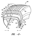
ここで図1および2を参照すると、本発明によるタイヤ100の例示的実施形態が提供されている。矢印Aは軸方向を指し、軸方向はそれを中心にタイヤ100が作動中に回転するはずである軸に平行であり、外周面CPに垂直である。矢印Rは径方向を指し、径方向は回転軸に垂直であり外周面CPに平行である。
Referring now to FIGS. 1 and 2, an exemplary embodiment of a
タイヤ100は、サイドウォール部130の間に延在するトレッド140を含む。グルーブ145は、トレッド140内のリブ155を分離する。各サイドウォール部130はクラウン部135内のトレッド140とビード部150との間に延在し、ビード部150はサイドウォール部130の径方向の内方に配置される。ビード部150のそれぞれはビードコア105およびビードエイペックス120を備える。
サイドウォール部130はビード部150の間に延在するカーカス110を保護する働きをする。またカーカス110は、タイヤ100のそれぞれの側部に沿ってビードコア105およびビードエイペックス120の周囲を覆う。しかし、本発明は、その中でカーカス110がビードコア105および/またはビードエイペックス120の周囲を覆うタイヤ構造に限定されず、その代わりに、その中でたとえばカーカス端部がビード部内に固定された他の構造も含むことを理解されたい。カーカス110は、例として鋼鉄およびポリエステル、ナイロンまたはレーヨンなどの様々な織物材料を含む、様々な材料から構成されてもよい。
The
図1および2の例示的実施形態に対して、タイヤ100はタイヤ100の内表面を覆うインナーライナー115を含む。インナーライナー115は、タイヤの膨張圧の保持に適切なあらゆる材料から構成されてもよい。たとえば、インナーライナー115は、ハロブチルゴムから構成されてもよい。ゴムの内層125は、インナーライナー115とカーカス110との間に配置される。内層125はタイヤ100に対して径方向Rに沿って追加の支持を提供する。
For the exemplary embodiment of FIGS. 1 and 2, the
本明細書に開示された教示を使用して、当業者には、本発明がたとえば図1および2に示され上述されたように、タイヤ100に限定されないことを理解されよう。その代わりに、他の構造のタイヤが同様に使用されてもよい。たとえば、異なる特徴をもつトレッド140が使用されてもよい。サイドウォール130およびビード部150に対して異なる構造をもつタイヤも使用されてもよい。タイヤは、所望通りにトレッド140と補強構造160(以下により完全に記載される)との間のクラウン領域内に追加の従来の補強ベルトまたは保護ベルトを含んでもよい。たとえば、所期の適用に依存して、追加のベルトが、カーカス110およびインナーライナー115を保護するために所望されてもよい。
Using the teachings disclosed herein, one of ordinary skill in the art will appreciate that the present invention is not limited to
図1に示されたように、タイヤ100は、トレッド140の径方向に内方の位置でクラウン部135内に配置された補強構造160を含む。補強構造160は、約5GPa以上の周方向の拡張係数および約10MPa以上の軸平面の弾性係数を有する。したがって、補強構造160は先に記載されたヒンジ効果に耐性があるタイヤ100に剛性を提供する。
As shown in FIG. 1, the
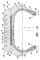
様々な構造を使用して、補強構造160に必要な機械的特徴を提供してもよい。図1および2に示された例示的実施形態に対して、補強構造160は、タイヤ100の回転軸を中心にコイル状の手法で巻かれ、樹脂175内に組み込まれた最小の1つのフィラメント170を含む層165から構成される。この例示的実施形態のために、外周面CPに対するこのようなフィラメント170の大半に対する角α(図2)は、約ゼロ度である。しかし、他の構造も同様に使用されてもよい。たとえば、フィラメント170に±45度の角αはまた、フィラメントが層165の周方向に沿って交差手法で巻かれるように使用されてもよい。層165の(すなわち、径方向に沿った)厚さは、たとえば、少なくとも約1〜5mmでよいが、他の厚さが使用されてもよい。好ましくは、層165の(すなわち、軸方向に沿った)幅は、実質的にクラウン部135と同じ幅である。
Various structures may be used to provide the necessary mechanical features for the reinforcing
上述の機械的特徴を満たすあらゆる適切な材料が、フィラメント170および樹脂175の製造に使用されてもよい。例として、繊維およびマトリクス材料は様々な形で市販のものを入手できる。繊維は個別に、または連続して束ねられているがよられていない繊維群であるロービングとして入手可能である。繊維は、マトリクス材料として続いて使用されるポリエステル樹脂などの樹脂材料で飽和されることが多い。このプロセスは、予備含浸を指す。これらの組合せはテープ、布、またはマットの形をとることができる。次いでこれらの材料は、補強構造の所望の寸法で蓄えられ、次いでそれによって樹脂が、熱または紫外線放射を含む多くの手段を使用して重合される。この硬化は、繊維と樹脂との間に恒久的な接着を生み出す。Jones著「Mechanics of Composite Materials」1975年参照。例として、補強構造160に使用され得るような複合リングの製造のための方法およびデバイスは、参照として本明細書に組み込まれる、国際公開第2008/080535号に記載されている。さらなる例として、予備含浸された複合繊維技術も、このような繊維を所望の形状の周囲を覆うこと、およびこのような繊維を加圧滅菌器内で硬化することにより、補強構造160を製造するために使用されてもよい。
Any suitable material that meets the mechanical characteristics described above may be used in the manufacture of
繊維は、数ミクロンの直径の多数の(数百程度の)個々の繊維を概して備える紡績糸(またはロービング)として提供されてもよく、これらの繊維はすべて隣接しており、したがって、多少の重複を除いて互いに実質的に平行である。繊維は全く完全に平行に配置されることを保証することは実際には不可能であるが、表現「互いに実質的に平行」は、編まれた糸または紐ではなく、繊維が配置の幾何学的精度を除いて平行に配置されることを示すことが意図される。 The fibers may be provided as spun yarns (or rovings) generally comprising a large number (in the hundreds) of individual fibers with a diameter of a few microns, all of these fibers being adjacent and thus somewhat overlapping Are substantially parallel to each other except. Although it is not practically possible to ensure that the fibers are arranged completely in parallel, the expression “substantially parallel to each other” is not a knitted yarn or string, but the geometry of the arrangement of the fibers It is intended to show that they are arranged in parallel except for accuracy.
別の公知の可能性は、特にフィラメントの長さの不連続な製造に適しており、鋳型内に所望通りに繊維を配置すること、真空を生成すること、そして最後に樹脂を含む繊維を含浸することからなる。真空により繊維の非常に有効な含浸が可能になる。米国特許第3,730,678号には、こうした含浸技術が示されている。 Another known possibility is particularly suitable for the discontinuous production of filament lengths, placing the fibers in the mold as desired, creating a vacuum, and finally impregnating the fibers containing the resin Made up of. The vacuum allows a very effective impregnation of the fibers. U.S. Pat. No. 3,730,678 shows such an impregnation technique.
例として、補強構造のフィラメントは、ポリビニルアルコール繊維、芳香族ポリアミド(すなわち「アラミド」)繊維、ポリアミドイミド繊維、ポリイミド繊維、ポリエステル繊維、芳香族ポリエステル繊維、ポリエチレン繊維、ポリプロピレン繊維、セルロース繊維、レーヨン繊維、ビスコース繊維、ポリフェニレンベンゾビスオキサゾール(すなわち「PBO」)繊維、ポリエチレンナフテネート(「PEN」)繊維、ガラス繊維、炭素繊維、石英繊維、セラミック繊維、およびこのような繊維の混合物を含む群から選択された繊維から構成されることが可能である。他の材料もフィラメントの構造に適切であることがある。 For example, the reinforcing structure filaments are polyvinyl alcohol fibers, aromatic polyamide (or “aramid”) fibers, polyamideimide fibers, polyimide fibers, polyester fibers, aromatic polyester fibers, polyethylene fibers, polypropylene fibers, cellulose fibers, rayon fibers. From the group comprising: viscose fibers, polyphenylenebenzobisoxazole (or “PBO”) fibers, polyethylene naphthenate (“PEN”) fibers, glass fibers, carbon fibers, quartz fibers, ceramic fibers, and mixtures of such fibers It can be composed of selected fibers. Other materials may be suitable for the filament structure.
樹脂175は、好ましくは樹脂175における繊維の圧縮に続くマイクロバックリングの急速な崩壊を回避するように、織物繊維の間に十分な結合を提供するように選択される。たとえば、ビニールエステルまたはエポキシ樹脂を使用することができる。また補強構造160に対して必要な機械的特徴を提供する他の樹脂が使用されてもよい。
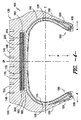
図3は、補強構造160を有する本発明のタイヤ100の別の例示的実施形態を提供する。図1および2の実施形態と同様に、補強構造160は、約5GPa以上の周方向の拡張係数および約10MPa以上の軸平面の弾性係数を有する。好ましくは、補強構造160の幅は、実質的にクラウン部135と同じ幅である。同様に、構造160に対して少なくとも約1mm〜約5mmの厚さが使用されてもよいが、他の厚さも同様に使用されてもよい。
FIG. 3 provides another exemplary embodiment of the
補強構造160は、先に記載されたように、樹脂175と共にタイヤの回転軸を中心にコイル状の手法で巻かれた、最小の1つのフィラメント170を含む層165を含む。図1および2の実施形態と異なる手法では、補強構造160は支持バンド180も含む。層165の径方向の外方の位置に示されているが、支持バンド180は層165の径方向の内方に配置されることも可能であることを理解されたい。
Reinforcing
支持バンド180は、金属ケーブル190および弾性として公知の拡張可能な補強材料185から構成される。たとえば、金属ケーブル190を低い拡張性で提供することができ、外周面CPと45度〜90度をなす角度を作る。金属コードまたはより糸190は、通常所与のプライまたは層内部で互いに対して平行である。加えて、支持バンド180は、金属ケーブル190の複数のこのような層またはプライを含むことができ、プライ間のケーブル190の角度はプライによって異なる。また、支持バンド180の複数のプライは、三角補強を提供することができ、三角補強はそれが経験する様々な応力下でほとんど変形しない。支持バンド180に使用され得る構造は、たとえば、米国特許出願公開第2010/0170610号、第2010/0147438号、第2009/0084485号、第2010/0294413号、および第2010/00282389号に説明されている。たとえば、このようなものは、米国特許出願公開第2010/0170610号において保護層と呼ばれている。
The
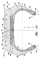
図4は、また補強構造160を有する本発明のタイヤ100の別の例示的実施形態を示す。図1および1の実施形態と同様に、補強構造160は、約5GPa以上の周方向の拡張係数および約10MPa以上の軸平面の弾性係数を有する。しかし、図1および2と異なる手法で、図4の補強構造160は複数の層を含む。より具体的には、補強構造160は層165、195、および200を含む。このような層のそれぞれは、層165に対して先に記載されたように、軸方向を中心に巻かれた少なくとも1つのフィラメントから構成される。層165、195、および200のフィラメントは、それぞれ0度の角度αで配向される。別法として、各層のフィラメントは、オフセット角で設定されてもよい。たとえば、層165のフィラメントは、+45度の角α、層195は−45度の角α、また層200は+45度の角αで実質的に配置されてもよい。他の構成も同様に使用されてもよい。
FIG. 4 also shows another exemplary embodiment of the
分離層205および210は層165、195、および200との間に配置される。例として、分離層205および210はゴム材料から構成され、約1mm未満の径方向に沿った厚さを有してもよい。しかし、他の材料、たとえばポリウレタンを同様に分離層に使用してもよい。同様に、この例示的実施形態に対して、層165、195、および200も約1mm未満の径方向に沿った厚さを有してもよい。好ましくは、補強構造160の幅は、実質的にクラウン部135と同じ幅である。同様に、構造160に対して少なくとも約1mm〜約5mmの全厚さを使用してよいが、他の厚さも同様に使用してよい。
Separation layers 205 and 210 are disposed between
図5は、本発明に従って構成されたタイヤ100のさらに別の例示的実施形態を示す。この例示的実施形態に対して、補強構造160は層165および支持バンド180を含む。先の実施形態と違い、層165はフィラメントを含まず、代わりに樹脂175のみから構成される。たとえば、樹脂はナイロン66、ポリウレタン、熱可塑性プラスチック、熱硬化性樹脂、または他の高分子材料から構成されることが可能である。支持バンド180は、先に記載されたように構成され、タイヤの回転軸を中心に巻かれた金属ケーブル190の層を含む。ケーブル190は、ゴム材料の層185内に配置される。図5に示されたように、支持バンド180は層165から径方向に離間されてもよい。別法として、支持バンド180は層165に直接隣接して、または層165と接触してもよい。支持バンド180は、図5に示されたように層165の径方向に外方に配置されてもよく、または別法として、層165の径方向に内方に配置されてもよい。補強構造160は、約5GPa以上の周方向の拡張係数および約10MPa以上の軸平面の弾性係数を有する。好ましくは、補強構造160の幅は、実質的にクラウン部135と同じ幅である。同様に、構造160に対して少なくとも約1mm〜約5mmの全厚さを使用してよいが、他の厚さを同様に使用してもよい。
FIG. 5 illustrates yet another exemplary embodiment of a
図6は、本発明の実施形態の有効性を検証するように設計されたシミュレーションからのある種のデータを表す。より具体的には、図6は、本発明の補強バンド160を備えて構成されたタイヤの径方向に沿った剛性の、補強バンド160を有さない参考タイヤに対する割合の様々な荷重に対するグラフを提供する。示されたように、補強バンド160の剛性により、タイヤ100はより低い偏向で作動することが可能になり、これは耐久性を向上させ、かつ/または積載量を増加させることができる。さらなる例として、示された最大荷重条件で、シミュレーションは、26%の剛性の増加が予想される一方で、偏向は7.7mm低減される。
FIG. 6 represents certain data from a simulation designed to verify the effectiveness of an embodiment of the present invention. More specifically, FIG. 6 is a graph of various loads in proportion to the reference tire without the
またシミュレーションを使用して、熱効果も同様に検証された。補強バンド160を備えるタイヤは、参考タイヤと比較したように、使用中に最大タイヤ温度で23.5℃低減できることが発見された。この低減は、タイヤの機能に加えないタイヤのクラウン部内からの寄生応力の除去によってもたらされると考えられる。
Using simulation, the thermal effect was verified as well. It has been discovered that a tire with a reinforcing
またシミュレーションにより、補強バンド160を備えるタイヤ内の周方向に沿った接触応力はより均一であることが明らかになった。したがって、より低い荷重感度と共に、補強バンド160を備えるタイヤは参考設計に対してトレッド摩耗の向上を実現するべきであることを、シミュレーションは示す。したがって、ヒンジ効果の低減もトレッド摩耗に向上をもたらした。
The simulation also revealed that the contact stress along the circumferential direction in the tire including the reinforcing
本主題は、特定の例示的実施形態およびその方法に関連して詳細に記載されているが、前述の理解を達成すれば、当業者はこのような実施形態の代替形態、変形形態、および等価物を容易に考え出し得ることが理解されよう。したがって、本開示の範囲は、限定としてよりむしろ例として存在し、主題の開示は、当業者であれば容易に分かるように、本主題に対するかかる修正形態、変形形態および/または追加の包含を排除しない。 Although the present subject matter has been described in detail in connection with certain exemplary embodiments and methods thereof, those of ordinary skill in the art will appreciate alternatives, variations, and equivalents of such embodiments, provided that the above understanding is achieved. It will be appreciated that things can be easily devised. Accordingly, the scope of the present disclosure exists as an example rather than a limitation, and the disclosure of the subject matter excludes such modifications, variations, and / or additional inclusions to the subject matter, as will be readily apparent to those skilled in the art. do not do.
Claims (18)
トレッドを有するクラウン部と、
前記クラウン部内に延在し前記トレッドの径方向に内方に配置される補強構造であって、前記補強構造は、約5GPa以上の周方向の拡張係数および約10MPa以上の軸平面の弾性係数を有する、補強構造と、
1対の軸方向に離間した環状ビード部と、
前記クラウン部のそれぞれの軸縁部とそれぞれの前記ビード部との間に径方向に延在するそれぞれのサイドウォールを備える、1対のサイドウォール部と、
前記ビード部の間に前記サイドウォール部を通って、また前記クラウン部を通って延在するカーカスプライであって、前記カーカスプライは、前記クラウン部内の前記補強バンドの径方向に内方に配置される、カーカスプライと、を備えるタイヤ。 A tire having a rotational axis and defining a radial direction, the tire having a crown portion having a tread;
A reinforcing structure that extends into the crown portion and is arranged inward in the radial direction of the tread, wherein the reinforcing structure has a circumferential expansion coefficient of about 5 GPa or more and an elastic modulus of an axial plane of about 10 MPa or more. Having a reinforcing structure;
A pair of axially spaced annular bead portions;
A pair of sidewall portions comprising respective sidewalls extending radially between each axial edge portion of the crown portion and each bead portion;
A carcass ply extending through the sidewall portion between the bead portions and through the crown portion, wherein the carcass ply is disposed inward in a radial direction of the reinforcing band in the crown portion; A carcass ply.
Applications Claiming Priority (1)
| Application Number | Priority Date | Filing Date | Title |
|---|---|---|---|
| PCT/US2011/025584 WO2012115615A1 (en) | 2011-02-21 | 2011-02-21 | Tire with crown reinforcing structure |
Publications (2)
| Publication Number | Publication Date |
|---|---|
| JP2014506546A true JP2014506546A (en) | 2014-03-17 |
| JP2014506546A5 JP2014506546A5 (en) | 2015-01-08 |
Family
ID=46721140
Family Applications (1)
| Application Number | Title | Priority Date | Filing Date |
|---|---|---|---|
| JP2013555399A Pending JP2014506546A (en) | 2011-02-21 | 2011-02-21 | Tire with crown reinforcement structure |
Country Status (7)
| Country | Link |
|---|---|
| US (1) | US20130327459A1 (en) |
| EP (1) | EP2678173A4 (en) |
| JP (1) | JP2014506546A (en) |
| CN (1) | CN103402790B (en) |
| BR (1) | BR112013021360A2 (en) |
| MX (1) | MX2013009641A (en) |
| WO (1) | WO2012115615A1 (en) |
Cited By (3)
| Publication number | Priority date | Publication date | Assignee | Title |
|---|---|---|---|---|
| JP2017206207A (en) * | 2016-05-20 | 2017-11-24 | 株式会社ブリヂストン | tire |
| WO2019003738A1 (en) * | 2017-06-30 | 2019-01-03 | 株式会社ブリヂストン | Reinforcing member for tires and tire using same |
| JP2019217870A (en) * | 2018-06-19 | 2019-12-26 | 株式会社ブリヂストン | Pneumatic tire |
Families Citing this family (11)
| Publication number | Priority date | Publication date | Assignee | Title |
|---|---|---|---|---|
| FR3009225B1 (en) | 2013-08-01 | 2015-07-31 | Michelin & Cie | MONOBRIN IN CVR (COMPOSITE GLASS-RESIN) IMPROVED |
| JP6348713B2 (en) * | 2014-01-09 | 2018-06-27 | 住友ゴム工業株式会社 | Pneumatic tire |
| EP3110633B1 (en) * | 2014-02-27 | 2020-08-05 | Compagnie Générale des Etablissements Michelin | Improved body ply shape for a tire |
| FR3036651B1 (en) * | 2015-05-28 | 2017-05-19 | Michelin & Cie | MULTI-COMPOSITE FLAT REINFORCEMENT |
| CN107743448B (en) * | 2015-06-16 | 2019-08-16 | 米其林集团总公司 | Pneumatic tire with the crown for including enhancing casing ply and high traction tyre surface |
| FR3039095B1 (en) * | 2015-07-21 | 2018-05-04 | Compagnie Generale Des Etablissements Michelin | PNEUMATIC COMPRISING REINFORCING ELEMENTS IN THE FORM OF MULTI-LAYER STRIPES |
| FR3045464B1 (en) * | 2015-12-16 | 2017-12-22 | Michelin & Cie | PNEUMATIC HAVING IMPROVED WEAR PROPERTIES |
| US11167595B2 (en) | 2017-11-10 | 2021-11-09 | Paccar Inc | Tire tread with reduced rolling resistance |
| CN109334352A (en) * | 2018-09-12 | 2019-02-15 | 三橡股份有限公司 | A kind of radial air tire |
| FR3089993A3 (en) | 2018-12-18 | 2020-06-19 | Michelin & Cie | Resin composition comprising a specific crosslinking agent |
| FR3089995A3 (en) | 2018-12-18 | 2020-06-19 | Michelin & Cie | Resin composition comprising a specific crosslinking agent |
Citations (5)
| Publication number | Priority date | Publication date | Assignee | Title |
|---|---|---|---|---|
| JPS61119404A (en) * | 1984-11-15 | 1986-06-06 | Yokohama Rubber Co Ltd:The | Pneumatic tire |
| JPS63162304A (en) * | 1986-12-26 | 1988-07-05 | Yokohama Rubber Co Ltd:The | Pneumatic radial tire |
| JPH04110208A (en) * | 1990-08-31 | 1992-04-10 | Bridgestone Corp | Pneumatic radial tyre |
| JPH11189009A (en) * | 1997-12-26 | 1999-07-13 | Yokohama Rubber Co Ltd:The | Pneumatic tire |
| JPH11321233A (en) * | 1998-05-18 | 1999-11-24 | Yokohama Rubber Co Ltd:The | Pneumatic radial tire |
Family Cites Families (11)
| Publication number | Priority date | Publication date | Assignee | Title |
|---|---|---|---|---|
| JPS5893607A (en) * | 1981-11-30 | 1983-06-03 | Yokohama Rubber Co Ltd:The | Pneumatic tire |
| US4688615A (en) * | 1985-05-28 | 1987-08-25 | The Goodyear Tire & Rubber Company | Reinforcing structure for a rubber article |
| US4823857A (en) * | 1988-03-16 | 1989-04-25 | The Goodyear Tire & Rubber Company | Tire beads |
| US6267165B1 (en) * | 1998-06-19 | 2001-07-31 | The Goodyear Tire & Rubber Company | Pneumatic tire with specified aramid belt |
| US6851463B1 (en) * | 1999-04-08 | 2005-02-08 | Alliedsignal Inc. | Composite comprising organic fibers having a low twist multiplier and improved compressive modulus |
| US6634398B1 (en) * | 1999-04-22 | 2003-10-21 | The Goodyear Tire & Rubber Company | Chip resistance tire |
| DE60125641T2 (en) * | 2000-06-22 | 2007-10-04 | Conception Et Development Michelin S.A. | Tire reinforced with a composite element and composite element |
| US6439288B1 (en) * | 2000-11-28 | 2002-08-27 | Bridgestone/Firestone North American Tire, Llc | Pneumatic tire with variable thickness band element |
| FR2887810A1 (en) * | 2005-06-30 | 2007-01-05 | Michelin Soc Tech | PNEUMATIC FOR HEAVY VEHICLES |
| FR2916159B1 (en) * | 2007-05-14 | 2011-03-18 | Michelin Soc Tech | PNEUMATIC FOR HEAVY VEHICLES |
| FR2939722B1 (en) * | 2008-12-17 | 2010-12-31 | Michelin Soc Tech | TIRE FOR HEAVY VEHICLES WITH TOP FRAME COMPRISING AT LEAST ONE LAYER OF CIRCUMFERENTIAL REINFORCING ELEMENTS |
-
2011
- 2011-02-21 MX MX2013009641A patent/MX2013009641A/en unknown
- 2011-02-21 US US14/000,767 patent/US20130327459A1/en not_active Abandoned
- 2011-02-21 JP JP2013555399A patent/JP2014506546A/en active Pending
- 2011-02-21 CN CN201180068865.6A patent/CN103402790B/en not_active Expired - Fee Related
- 2011-02-21 EP EP11859034.8A patent/EP2678173A4/en not_active Withdrawn
- 2011-02-21 WO PCT/US2011/025584 patent/WO2012115615A1/en active Application Filing
- 2011-02-21 BR BR112013021360A patent/BR112013021360A2/en not_active IP Right Cessation
Patent Citations (5)
| Publication number | Priority date | Publication date | Assignee | Title |
|---|---|---|---|---|
| JPS61119404A (en) * | 1984-11-15 | 1986-06-06 | Yokohama Rubber Co Ltd:The | Pneumatic tire |
| JPS63162304A (en) * | 1986-12-26 | 1988-07-05 | Yokohama Rubber Co Ltd:The | Pneumatic radial tire |
| JPH04110208A (en) * | 1990-08-31 | 1992-04-10 | Bridgestone Corp | Pneumatic radial tyre |
| JPH11189009A (en) * | 1997-12-26 | 1999-07-13 | Yokohama Rubber Co Ltd:The | Pneumatic tire |
| JPH11321233A (en) * | 1998-05-18 | 1999-11-24 | Yokohama Rubber Co Ltd:The | Pneumatic radial tire |
Cited By (4)
| Publication number | Priority date | Publication date | Assignee | Title |
|---|---|---|---|---|
| JP2017206207A (en) * | 2016-05-20 | 2017-11-24 | 株式会社ブリヂストン | tire |
| WO2019003738A1 (en) * | 2017-06-30 | 2019-01-03 | 株式会社ブリヂストン | Reinforcing member for tires and tire using same |
| JP2019217870A (en) * | 2018-06-19 | 2019-12-26 | 株式会社ブリヂストン | Pneumatic tire |
| WO2019244699A1 (en) * | 2018-06-19 | 2019-12-26 | 株式会社ブリヂストン | Pneumatic tire |
Also Published As
| Publication number | Publication date |
|---|---|
| EP2678173A1 (en) | 2014-01-01 |
| BR112013021360A2 (en) | 2018-06-26 |
| CN103402790A (en) | 2013-11-20 |
| MX2013009641A (en) | 2013-12-16 |
| US20130327459A1 (en) | 2013-12-12 |
| CN103402790B (en) | 2016-08-10 |
| EP2678173A4 (en) | 2014-09-17 |
| WO2012115615A1 (en) | 2012-08-30 |
Similar Documents
| Publication | Publication Date | Title |
|---|---|---|
| JP2014506546A (en) | Tire with crown reinforcement structure | |
| JP6836595B2 (en) | An assembly intended for tires containing woven or knitted fabrics containing pre-bonded wire elements | |
| JP7324143B2 (en) | Assembly including partially breakable fabric and support structure | |
| CN105564161B (en) | Pneumatic tire with three-dimensional micromodule | |
| US11325418B2 (en) | Tire assembly comprising a breakable structure and a supporting structure | |
| JP2014506546A5 (en) | ||
| JP6872958B2 (en) | Lightweight tires | |
| JP7249344B2 (en) | non-pneumatic wheels | |
| JP5868085B2 (en) | Pneumatic tire forming method | |
| CN104228465A (en) | Hybrid cord for penumatic tire | |
| CN108136841B (en) | Pneumatic tire comprising a reinforcing element in the form of a multilayer strip | |
| CN103373177A (en) | Accordion spiral overlay for a pneumatic tire | |
| KR20120036290A (en) | A pneumatic tire with a knitted flipper | |
| US20150041039A1 (en) | Pneumatic tire with a reinforced flipper or chipper | |
| EP2527162B1 (en) | Carcass ply structure for a pneumatic tire | |
| EP3081396B1 (en) | A bidirectional monobelt construction for a pneumatic tire | |
| US20200231012A1 (en) | Tire having a reinforced lower zone | |
| JP2012091778A (en) | Reduced weight aircraft tire | |
| JP3001221B2 (en) | Pneumatic radial tire for heavy loads | |
| KR102327709B1 (en) | A non-pneumatic tire including reinforcing structure part | |
| WO2019102918A1 (en) | Run-flat tire | |
| JP2006131080A (en) | Pneumatic tire | |
| US8561661B2 (en) | Run-flat pneumatic tire assembly and method | |
| CN103112318A (en) | Pneumatic tire and method of manufacturing a pneumatic tire |
Legal Events
| Date | Code | Title | Description |
|---|---|---|---|
| A521 | Written amendment |
Free format text: JAPANESE INTERMEDIATE CODE: A523 Effective date: 20131007 |
|
| A621 | Written request for application examination |
Free format text: JAPANESE INTERMEDIATE CODE: A621 Effective date: 20131007 |
|
| A977 | Report on retrieval |
Free format text: JAPANESE INTERMEDIATE CODE: A971007 Effective date: 20140609 |
|
| A131 | Notification of reasons for refusal |
Free format text: JAPANESE INTERMEDIATE CODE: A131 Effective date: 20140611 |
|
| A601 | Written request for extension of time |
Free format text: JAPANESE INTERMEDIATE CODE: A601 Effective date: 20140910 |
|
| A602 | Written permission of extension of time |
Free format text: JAPANESE INTERMEDIATE CODE: A602 Effective date: 20140918 |
|
| A601 | Written request for extension of time |
Free format text: JAPANESE INTERMEDIATE CODE: A601 Effective date: 20141010 |
|
| A602 | Written permission of extension of time |
Free format text: JAPANESE INTERMEDIATE CODE: A602 Effective date: 20141020 |
|
| A524 | Written submission of copy of amendment under section 19 (pct) |
Free format text: JAPANESE INTERMEDIATE CODE: A524 Effective date: 20141113 |
|
| A02 | Decision of refusal |
Free format text: JAPANESE INTERMEDIATE CODE: A02 Effective date: 20150511 |