JP2014506151A - Foam dressing with integrated porous film - Google Patents
Foam dressing with integrated porous film Download PDFInfo
- Publication number
- JP2014506151A JP2014506151A JP2013544684A JP2013544684A JP2014506151A JP 2014506151 A JP2014506151 A JP 2014506151A JP 2013544684 A JP2013544684 A JP 2013544684A JP 2013544684 A JP2013544684 A JP 2013544684A JP 2014506151 A JP2014506151 A JP 2014506151A
- Authority
- JP
- Japan
- Prior art keywords
- wound
- channel
- wound insert
- porous film
- foam member
- Prior art date
- Legal status (The legal status is an assumption and is not a legal conclusion. Google has not performed a legal analysis and makes no representation as to the accuracy of the status listed.)
- Pending
Links
- 239000006260 foam Substances 0.000 title claims description 59
- 238000000034 method Methods 0.000 claims description 21
- 238000010438 heat treatment Methods 0.000 claims description 6
- 238000009950 felting Methods 0.000 claims description 5
- 238000004519 manufacturing process Methods 0.000 claims description 5
- 230000009545 invasion Effects 0.000 claims description 3
- 238000003698 laser cutting Methods 0.000 claims description 3
- 206010052428 Wound Diseases 0.000 abstract description 90
- 208000027418 Wounds and injury Diseases 0.000 abstract description 90
- 239000012530 fluid Substances 0.000 description 22
- 229920000747 poly(lactic acid) Polymers 0.000 description 15
- -1 polypropylene Polymers 0.000 description 15
- 229920000181 Ethylene propylene rubber Polymers 0.000 description 10
- 244000043261 Hevea brasiliensis Species 0.000 description 10
- 229920002614 Polyether block amide Polymers 0.000 description 10
- 239000004698 Polyethylene Substances 0.000 description 10
- 239000004743 Polypropylene Substances 0.000 description 10
- 239000004372 Polyvinyl alcohol Substances 0.000 description 10
- 229920001971 elastomer Polymers 0.000 description 10
- 229920003052 natural elastomer Polymers 0.000 description 10
- 229920001194 natural rubber Polymers 0.000 description 10
- 229920001610 polycaprolactone Polymers 0.000 description 10
- 239000004632 polycaprolactone Substances 0.000 description 10
- 229920000728 polyester Polymers 0.000 description 10
- 229920000573 polyethylene Polymers 0.000 description 10
- 229920001155 polypropylene Polymers 0.000 description 10
- 229920002451 polyvinyl alcohol Polymers 0.000 description 10
- 229920002037 poly(vinyl butyral) polymer Polymers 0.000 description 8
- 210000001519 tissue Anatomy 0.000 description 7
- 206010063560 Excessive granulation tissue Diseases 0.000 description 5
- 239000004952 Polyamide Substances 0.000 description 5
- 229920000954 Polyglycolide Polymers 0.000 description 5
- 239000004721 Polyphenylene oxide Substances 0.000 description 5
- 238000007906 compression Methods 0.000 description 5
- 230000006835 compression Effects 0.000 description 5
- 239000000806 elastomer Substances 0.000 description 5
- 239000005038 ethylene vinyl acetate Substances 0.000 description 5
- 210000001126 granulation tissue Anatomy 0.000 description 5
- 239000000463 material Substances 0.000 description 5
- 229920002647 polyamide Polymers 0.000 description 5
- 229920000570 polyether Polymers 0.000 description 5
- 229920002643 polyglutamic acid Polymers 0.000 description 5
- 239000004633 polyglycolic acid Substances 0.000 description 5
- 239000004626 polylactic acid Substances 0.000 description 5
- 229920000642 polymer Polymers 0.000 description 5
- 229920000098 polyolefin Polymers 0.000 description 5
- 239000004800 polyvinyl chloride Substances 0.000 description 5
- 229920000915 polyvinyl chloride Polymers 0.000 description 5
- 239000005060 rubber Substances 0.000 description 5
- 229920005573 silicon-containing polymer Polymers 0.000 description 5
- 229920003048 styrene butadiene rubber Polymers 0.000 description 5
- 229920002725 thermoplastic elastomer Polymers 0.000 description 5
- 229920002554 vinyl polymer Polymers 0.000 description 5
- DHKHKXVYLBGOIT-UHFFFAOYSA-N acetaldehyde Diethyl Acetal Natural products CCOC(C)OCC DHKHKXVYLBGOIT-UHFFFAOYSA-N 0.000 description 4
- 125000002777 acetyl group Chemical class [H]C([H])([H])C(*)=O 0.000 description 4
- BLAJPPMSXMTCLR-UHFFFAOYSA-N but-1-ene styrene Chemical compound CCC=C.C=CC1=CC=CC=C1.C=CC1=CC=CC=C1 BLAJPPMSXMTCLR-UHFFFAOYSA-N 0.000 description 4
- 230000035876 healing Effects 0.000 description 4
- 238000009581 negative-pressure wound therapy Methods 0.000 description 4
- 230000037313 granulation tissue formation Effects 0.000 description 3
- 230000002262 irrigation Effects 0.000 description 3
- 238000003973 irrigation Methods 0.000 description 3
- 229920000058 polyacrylate Polymers 0.000 description 3
- 229920002635 polyurethane Polymers 0.000 description 3
- 239000004814 polyurethane Substances 0.000 description 3
- 239000011148 porous material Substances 0.000 description 3
- 238000002560 therapeutic procedure Methods 0.000 description 3
- XLYOFNOQVPJJNP-UHFFFAOYSA-N water Substances O XLYOFNOQVPJJNP-UHFFFAOYSA-N 0.000 description 3
- 230000015572 biosynthetic process Effects 0.000 description 2
- 238000005520 cutting process Methods 0.000 description 2
- 238000010586 diagram Methods 0.000 description 2
- 230000035515 penetration Effects 0.000 description 2
- 230000002093 peripheral effect Effects 0.000 description 2
- 230000029663 wound healing Effects 0.000 description 2
- 230000003213 activating effect Effects 0.000 description 1
- 239000000853 adhesive Substances 0.000 description 1
- 230000001070 adhesive effect Effects 0.000 description 1
- 230000002411 adverse Effects 0.000 description 1
- 230000000844 anti-bacterial effect Effects 0.000 description 1
- XRERONKQLIQWGW-UHFFFAOYSA-N but-1-ene;styrene Chemical compound CCC=C.C=CC1=CC=CC=C1 XRERONKQLIQWGW-UHFFFAOYSA-N 0.000 description 1
- 238000010000 carbonizing Methods 0.000 description 1
- 238000004140 cleaning Methods 0.000 description 1
- 238000004891 communication Methods 0.000 description 1
- 229940079593 drug Drugs 0.000 description 1
- 239000003814 drug Substances 0.000 description 1
- 230000000694 effects Effects 0.000 description 1
- 238000005530 etching Methods 0.000 description 1
- 230000001788 irregular Effects 0.000 description 1
- 238000005304 joining Methods 0.000 description 1
- 238000010329 laser etching Methods 0.000 description 1
- 238000002483 medication Methods 0.000 description 1
- 238000012986 modification Methods 0.000 description 1
- 230000004048 modification Effects 0.000 description 1
- 238000000465 moulding Methods 0.000 description 1
- 230000000399 orthopedic effect Effects 0.000 description 1
- 238000003825 pressing Methods 0.000 description 1
- 238000007789 sealing Methods 0.000 description 1
- 238000009958 sewing Methods 0.000 description 1
- 239000000126 substance Substances 0.000 description 1
Images


Classifications
-
- A—HUMAN NECESSITIES
- A61—MEDICAL OR VETERINARY SCIENCE; HYGIENE
- A61F—FILTERS IMPLANTABLE INTO BLOOD VESSELS; PROSTHESES; DEVICES PROVIDING PATENCY TO, OR PREVENTING COLLAPSING OF, TUBULAR STRUCTURES OF THE BODY, e.g. STENTS; ORTHOPAEDIC, NURSING OR CONTRACEPTIVE DEVICES; FOMENTATION; TREATMENT OR PROTECTION OF EYES OR EARS; BANDAGES, DRESSINGS OR ABSORBENT PADS; FIRST-AID KITS
- A61F13/00—Bandages or dressings; Absorbent pads
- A61F13/05—Bandages or dressings; Absorbent pads specially adapted for use with sub-pressure or over-pressure therapy, wound drainage or wound irrigation, e.g. for use with negative-pressure wound therapy [NPWT]
-
- A—HUMAN NECESSITIES
- A61—MEDICAL OR VETERINARY SCIENCE; HYGIENE
- A61F—FILTERS IMPLANTABLE INTO BLOOD VESSELS; PROSTHESES; DEVICES PROVIDING PATENCY TO, OR PREVENTING COLLAPSING OF, TUBULAR STRUCTURES OF THE BODY, e.g. STENTS; ORTHOPAEDIC, NURSING OR CONTRACEPTIVE DEVICES; FOMENTATION; TREATMENT OR PROTECTION OF EYES OR EARS; BANDAGES, DRESSINGS OR ABSORBENT PADS; FIRST-AID KITS
- A61F13/00—Bandages or dressings; Absorbent pads
- A61F13/00987—Apparatus or processes for manufacturing non-adhesive dressings or bandages
- A61F13/00991—Apparatus or processes for manufacturing non-adhesive dressings or bandages for treating webs, e.g. for moisturising, coating, impregnating or applying powder
- A61F13/00995—Apparatus or processes for manufacturing non-adhesive dressings or bandages for treating webs, e.g. for moisturising, coating, impregnating or applying powder for mechanical treatments
-
- A—HUMAN NECESSITIES
- A61—MEDICAL OR VETERINARY SCIENCE; HYGIENE
- A61F—FILTERS IMPLANTABLE INTO BLOOD VESSELS; PROSTHESES; DEVICES PROVIDING PATENCY TO, OR PREVENTING COLLAPSING OF, TUBULAR STRUCTURES OF THE BODY, e.g. STENTS; ORTHOPAEDIC, NURSING OR CONTRACEPTIVE DEVICES; FOMENTATION; TREATMENT OR PROTECTION OF EYES OR EARS; BANDAGES, DRESSINGS OR ABSORBENT PADS; FIRST-AID KITS
- A61F13/00—Bandages or dressings; Absorbent pads
- A61F13/02—Adhesive bandages or dressings
- A61F13/0203—Adhesive bandages or dressings with fluid retention members
- A61F13/0226—Adhesive bandages or dressings with fluid retention members characterised by the support layer
-
- A—HUMAN NECESSITIES
- A61—MEDICAL OR VETERINARY SCIENCE; HYGIENE
- A61F—FILTERS IMPLANTABLE INTO BLOOD VESSELS; PROSTHESES; DEVICES PROVIDING PATENCY TO, OR PREVENTING COLLAPSING OF, TUBULAR STRUCTURES OF THE BODY, e.g. STENTS; ORTHOPAEDIC, NURSING OR CONTRACEPTIVE DEVICES; FOMENTATION; TREATMENT OR PROTECTION OF EYES OR EARS; BANDAGES, DRESSINGS OR ABSORBENT PADS; FIRST-AID KITS
- A61F13/00—Bandages or dressings; Absorbent pads
- A61F2013/00089—Wound bandages
- A61F2013/0017—Wound bandages possibility of applying fluid
- A61F2013/00174—Wound bandages possibility of applying fluid possibility of applying pressure
-
- A—HUMAN NECESSITIES
- A61—MEDICAL OR VETERINARY SCIENCE; HYGIENE
- A61F—FILTERS IMPLANTABLE INTO BLOOD VESSELS; PROSTHESES; DEVICES PROVIDING PATENCY TO, OR PREVENTING COLLAPSING OF, TUBULAR STRUCTURES OF THE BODY, e.g. STENTS; ORTHOPAEDIC, NURSING OR CONTRACEPTIVE DEVICES; FOMENTATION; TREATMENT OR PROTECTION OF EYES OR EARS; BANDAGES, DRESSINGS OR ABSORBENT PADS; FIRST-AID KITS
- A61F13/00—Bandages or dressings; Absorbent pads
- A61F2013/00361—Plasters
- A61F2013/00365—Plasters use
- A61F2013/00536—Plasters use for draining or irrigating wounds
-
- A—HUMAN NECESSITIES
- A61—MEDICAL OR VETERINARY SCIENCE; HYGIENE
- A61F—FILTERS IMPLANTABLE INTO BLOOD VESSELS; PROSTHESES; DEVICES PROVIDING PATENCY TO, OR PREVENTING COLLAPSING OF, TUBULAR STRUCTURES OF THE BODY, e.g. STENTS; ORTHOPAEDIC, NURSING OR CONTRACEPTIVE DEVICES; FOMENTATION; TREATMENT OR PROTECTION OF EYES OR EARS; BANDAGES, DRESSINGS OR ABSORBENT PADS; FIRST-AID KITS
- A61F13/00—Bandages or dressings; Absorbent pads
- A61F2013/00361—Plasters
- A61F2013/00365—Plasters use
- A61F2013/0054—Plasters use for deep wounds
-
- A—HUMAN NECESSITIES
- A61—MEDICAL OR VETERINARY SCIENCE; HYGIENE
- A61F—FILTERS IMPLANTABLE INTO BLOOD VESSELS; PROSTHESES; DEVICES PROVIDING PATENCY TO, OR PREVENTING COLLAPSING OF, TUBULAR STRUCTURES OF THE BODY, e.g. STENTS; ORTHOPAEDIC, NURSING OR CONTRACEPTIVE DEVICES; FOMENTATION; TREATMENT OR PROTECTION OF EYES OR EARS; BANDAGES, DRESSINGS OR ABSORBENT PADS; FIRST-AID KITS
- A61F13/00—Bandages or dressings; Absorbent pads
- A61F2013/00361—Plasters
- A61F2013/00544—Plasters form or structure
- A61F2013/00582—Properties of backing
- A61F2013/00587—Thickness
Landscapes
- Health & Medical Sciences (AREA)
- Engineering & Computer Science (AREA)
- Animal Behavior & Ethology (AREA)
- Heart & Thoracic Surgery (AREA)
- Vascular Medicine (AREA)
- Life Sciences & Earth Sciences (AREA)
- Biomedical Technology (AREA)
- General Health & Medical Sciences (AREA)
- Public Health (AREA)
- Veterinary Medicine (AREA)
- Manufacturing & Machinery (AREA)
- Media Introduction/Drainage Providing Device (AREA)
- Materials For Medical Uses (AREA)
Abstract
多孔質フィルム層と少なくとも1つのチャネルとを備える創傷ドレッシングおよび創傷インサート、多孔質フィルム層と少なくとも1つのチャネルとを備える創傷インサートを形成する創傷インサート、および創傷治療創傷インサート。 A wound dressing and wound insert comprising a porous film layer and at least one channel, a wound insert forming a wound insert comprising a porous film layer and at least one channel, and a wound treatment wound insert.
Description
関連出願の相互参照
本願は、2010年12月15日に出願された米国仮特許出願第61,423,405号明細書の優先権を主張する。この仮出願は、参照により明示的に援用される。
This application claims priority to US Provisional Patent Application No. 61,423,405, filed Dec. 15, 2010. This provisional application is expressly incorporated by reference.
本発明は、一般に、創傷治癒および創傷治療法に関する。より詳細には、本発明は、流体灌注(fluid−instillation)および陰圧創傷療法に関するが、これらに限定されるものではない。 The present invention relates generally to wound healing and wound treatment methods. More particularly, the present invention relates to, but is not limited to, fluid-instillation and negative pressure wound therapy.
臨床試験および実施から、組織部位の近傍に減圧を提供すると、その組織部位における新組織の増殖が促進され、加速されることが分かった。この現象の応用は多数あるが、減圧の印加は創傷治療に特に成果があった。この治療(医学界では「陰圧創傷療法」、「減圧療法」、または「真空療法」と称されることが多い)には、治癒の迅速化や肉芽組織形成の促進を含む、多くの利点がある。通常、減圧は創傷インサート(例えば、多孔質パッドまたは他のマニホールドデバイス)を通して組織に印加される。創傷インサートは、通常、組織に減圧を分配し、組織から吸引される流体を送流することができる気泡または気孔を含有する。創傷インサートを、例えば、ドレープ(例えば、粘着性サージカルドレープ)などの治療を促進する他の構成要素を有する創傷ドレッシングに組み込むことができる。灌注流体(例えば、洗浄液(irrigation fluids)および/または医薬)を陰圧創傷療法と併用し、治癒を促進するおよび/または有効性を向上することができる。創傷に薬理活性溶液を送達するシステムの一例は、米国特許第6,398,767号明細書に開示されている。 Clinical trials and practice have shown that providing reduced pressure in the vicinity of a tissue site promotes and accelerates the growth of new tissue at that tissue site. Although there are many applications of this phenomenon, the application of reduced pressure has been particularly successful in wound healing. This treatment (often referred to in the medical community as “negative pressure wound therapy”, “vacuum therapy”, or “vacuum therapy”) has many advantages, including faster healing and promotion of granulation tissue formation There is. Typically, reduced pressure is applied to the tissue through a wound insert (eg, a porous pad or other manifold device). Wound inserts typically contain bubbles or pores that can distribute a vacuum to the tissue and deliver fluid aspirated from the tissue. The wound insert can be incorporated into a wound dressing having other components that facilitate treatment, such as, for example, a drape (eg, an adhesive surgical drape). Irrigation fluid (eg, irrigation fluids and / or medications) can be used in conjunction with negative pressure wound therapy to promote healing and / or improve effectiveness. An example of a system for delivering a pharmacologically active solution to a wound is disclosed in US Pat. No. 6,398,767.
特定の用途では、創傷部位に陰圧を提供することは臨床的に有利であるが、肉芽組織の形成は望ましくない。例えば、プレート、ロッド、またはピンなどの器具を収容する整形外科創腔(orthopedic cavity wound)に陰圧を提供すると、これらの創傷のより迅速な治癒に役立ち得る。しかし、この器具の周囲での肉芽組織の形成は悪影響を及ぼし得る。 In certain applications, it is clinically advantageous to provide negative pressure at the wound site, but granulation tissue formation is undesirable. For example, providing negative pressure to an orthopedic cavity that houses instruments such as plates, rods, or pins can help in faster healing of these wounds. However, granulation tissue formation around the device can have an adverse effect.
創傷インサート、ならびにその製造方法および使用方法を提供する。 Wound inserts and methods for making and using the same are provided.
創傷インサートの製造方法の幾つかの実施形態は、網状連続気泡フォームを備える部材を得るステップであって、部材が第1の面、第2の面、および非圧縮厚みをさらに備えるステップ;第1の熱板と第2の熱板とを備える熱プレス機(platen press)を得るステップ;第1の熱板を第1の温度に加熱するステップ;第1の面が第1の熱板に面し、第2の面が第2の熱板に面するように部材を熱プレス機内に配置するステップ;および、部材を圧縮厚みになるまで圧縮時間圧縮するステップ;を含む。 Some embodiments of the method of manufacturing a wound insert include obtaining a member comprising a reticulated open cell foam, the member further comprising a first surface, a second surface, and an uncompressed thickness; Obtaining a hot press comprising a hot plate and a second hot plate; heating the first hot plate to a first temperature; the first surface facing the first hot plate And placing the member in the hot press so that the second surface faces the second hot plate; and compressing the member for a compression time until it reaches a compression thickness.
さらに、幾つかの実施形態は、部材の第1の面に多孔質フィルム層を形成するステップをさらに含んでもよい。他の実施形態は、部材の第2の面に多孔質フィルム層を形成するステップをさらに含んでもよい。さらに他の実施形態は、第1の面から多孔質フィルム層の一部を除去するステップをさらに含んでもよい。除去するステップは、レーザー切断、レーザーエッチング、打抜き、または水切断を含んでもよい。さらに他の実施形態は、多孔質フィルム層にチャネルを形成するステップをさらに含んでもよい。 Further, some embodiments may further include forming a porous film layer on the first side of the member. Other embodiments may further include forming a porous film layer on the second side of the member. Still other embodiments may further include removing a portion of the porous film layer from the first surface. The removing step may include laser cutting, laser etching, stamping, or water cutting. Still other embodiments may further include forming channels in the porous film layer.
特定の実施形態では、圧縮厚みは、非圧縮厚みの約10分の1、9分の1、8分の1、7分の1、6分の1、または5分の1未満である。幾つかの実施形態では、非圧縮厚みは約0.5インチであり、圧縮厚みは約0.05インチである。幾つかの実施形態では、第1の熱板、第2の熱板、またはその両方を約160℃〜約180℃の温度に加熱してもよく;特定の実施形態では、熱板を約175℃の温度に加熱してもよい。圧縮時間は約15分〜約30分であってもよい。 In certain embodiments, the compressed thickness is less than about 1/10, 1/9, 1/8, 1/7, 1/6, or 1/5 of the uncompressed thickness. In some embodiments, the uncompressed thickness is about 0.5 inches and the compressed thickness is about 0.05 inches. In some embodiments, the first hot plate, the second hot plate, or both may be heated to a temperature of about 160 ° C. to about 180 ° C .; in certain embodiments, the hot plate is about 175 You may heat to the temperature of (degreeC). The compression time may be about 15 minutes to about 30 minutes.
幾つかの実施形態では、部材は、ポリウレタン−ポリエステルまたはポリウレタン−ポリエーテルなどのポリウレタン;ポリプロピレン(PP)またはポリエチレン(PE)などのポリオレフィン;シリコーンポリマー;ポリ塩化ビニル;ポリアミド;ポリエステル;ポリアクリレート(acrylics);スチレン−ブテン−スチレン(SBS)またはスチレン−エチレン−ブテン−スチレン(SEBS)などの熱可塑性エラストマー;ポリエーテル−アミドブロック共重合体(PEBAX);スチレンブタジエンゴム(SBR)などのエラストマー;エチレンプロピレンゴム(EPR);エチレンプロピレンジエン変性ゴム(EPDM);天然ゴム(NR);エチレン酢酸ビニル(EVA);ポリビニルアルコール(PVOH);ポリビニルアセタール;またはポリビニルブチラール(PVB)を含んでもよい。さらに、フォーム部材は生体吸収性ポリマーを含んでもよく、その例としては、ポリ乳酸、ポリラクチド(PLA)、ポリグリコール酸、ポリグリコリド(PGA)、およびポリカプロラクトン(PCL)が挙げられる。 In some embodiments, the member comprises a polyurethane, such as polyurethane-polyester or polyurethane-polyether; a polyolefin, such as polypropylene (PP) or polyethylene (PE); a silicone polymer; a polyvinyl chloride; a polyamide; a polyester; ); Thermoplastic elastomers such as styrene-butene-styrene (SBS) or styrene-ethylene-butene-styrene (SEBS); polyether-amide block copolymers (PEBAX); elastomers such as styrene butadiene rubber (SBR); ethylene Propylene rubber (EPR); Ethylene propylene diene modified rubber (EPDM); Natural rubber (NR); Ethylene vinyl acetate (EVA); Polyvinyl alcohol (PVOH); Poly It may include or polyvinyl butyral (PVB); acetal. Further, the foam member may include a bioabsorbable polymer, examples of which include polylactic acid, polylactide (PLA), polyglycolic acid, polyglycolide (PGA), and polycaprolactone (PCL).
創傷インサートの製造方法の他の実施形態は、第1の面、第2の面、および第1の面と第2の面との間の厚みを有する網状連続気泡フォーム部材を得るステップ;部材の第1の面をフェルト化し、フェルト化された層を形成するステップ;およびフェルト化された層に少なくとも1つのチャネルを形成するステップを含む。 Another embodiment of a method for manufacturing a wound insert includes obtaining a reticulated open cell foam member having a first side, a second side, and a thickness between the first side and the second side; Felting the first surface to form a felted layer; and forming at least one channel in the felted layer.
特定の実施形態では、少なくとも1つのチャネルは前記厚みを通して第2の層と流体連通していてもよい。フェルト化するステップは、部材に熱と圧力を印加するステップをさらに含んでもよい。幾つかの実施形態では、形成するステップは、レーザー切断、水切断、または打抜きを含んでもよい。 In certain embodiments, at least one channel may be in fluid communication with the second layer through the thickness. Feltting may further include applying heat and pressure to the member. In some embodiments, the forming step may include laser cutting, water cutting, or stamping.
部材は、ポリウレタン−ポリエステルまたはポリウレタン−ポリエーテルなどのポリウレタン;ポリプロピレン(PP)またはポリエチレン(PE)などのポリオレフィン;シリコーンポリマー;ポリ塩化ビニル;ポリアミド;ポリエステル;ポリアクリレート;スチレン−ブテン−スチレン(SBS)またはスチレン−エチレン−ブテン−スチレン(SEBS)などの熱可塑性エラストマー;ポリエーテル−アミドブロック共重合体(PEBAX);スチレンブタジエンゴム(SBR)などのエラストマー;エチレンプロピレンゴム(EPR);エチレンプロピレンジエン変性ゴム(EPDM);天然ゴム(NR);エチレン酢酸ビニル(EVA);ポリビニルアルコール(PVOH);ポリビニルアセタール;またはポリビニルブチラール(PVB)を含んでもよい。さらに、フォーム部材は生体吸収性ポリマーを含んでもよく、その例としては、ポリ乳酸、ポリラクチド(PLA)、ポリグリコール酸、ポリグリコリド(PGA)、およびポリカプロラクトン(PCL)が挙げられる。 The component is a polyurethane such as polyurethane-polyester or polyurethane-polyether; a polyolefin such as polypropylene (PP) or polyethylene (PE); a silicone polymer; a polyvinyl chloride; a polyamide; a polyester; a polyacrylate; a styrene-butene-styrene (SBS). Or thermoplastic elastomer such as styrene-ethylene-butene-styrene (SEBS); polyether-amide block copolymer (PEBAX); elastomer such as styrene butadiene rubber (SBR); ethylene propylene rubber (EPR); ethylene propylene diene modified Rubber (EPDM); natural rubber (NR); ethylene vinyl acetate (EVA); polyvinyl alcohol (PVOH); polyvinyl acetal; or polyvinyl butyler (PVB) may contain. Further, the foam member may include a bioabsorbable polymer, examples of which include polylactic acid, polylactide (PLA), polyglycolic acid, polyglycolide (PGA), and polycaprolactone (PCL).
特定の実施形態は、創傷インサートに関する。幾つかの実施形態は、第1の面、第2の面、および第1の面と第2の面との間の厚みを備える網状連続気泡フォームを備え、網状連続気泡フォームの第1の面は、多孔質フィルム層と少なくとも1つのチャネルとを備える。 Particular embodiments relate to wound inserts. Some embodiments comprise a reticulated open cell foam comprising a first surface, a second surface, and a thickness between the first surface and the second surface, the first surface of the reticulated open cell foam. Comprises a porous film layer and at least one channel.
創傷インサートの実施形態は、ポリウレタン−ポリエステルまたはポリウレタン−ポリエーテル;ポリプロピレン(PP)またはポリエチレン(PE)などのポリオレフィン;シリコーンポリマー;ポリ塩化ビニル;ポリアミド;ポリエステル;ポリアクリレート;スチレン−ブテン−スチレン(SBS)またはスチレン−エチレン−ブテン−スチレン(SEBS)などの熱可塑性エラストマー;ポリエーテル−アミドブロック共重合体(PEBAX);スチレンブタジエンゴム(SBR)などのエラストマー;エチレンプロピレンゴム(EPR);エチレンプロピレンジエン変性ゴム(EPDM);天然ゴム(NR);エチレン酢酸ビニル(EVA);ポリビニルアルコール(PVOH);ポリビニルアセタール;またはポリビニルブチラール(PVB)を含んでもよい。さらに、フォーム部材は生体吸収性ポリマーを含んでもよく、その例としては、ポリ乳酸、ポリラクチド(PLA)、ポリグリコール酸、ポリグリコリド(PGA)、およびポリカプロラクトン(PCL)が挙げられる。 Embodiments of wound inserts include: polyurethane-polyester or polyurethane-polyether; polyolefins such as polypropylene (PP) or polyethylene (PE); silicone polymers; polyvinyl chloride; polyamides; polyesters; polyacrylates; styrene-butene-styrene (SBS) ) Or thermoplastic elastomers such as styrene-ethylene-butene-styrene (SEBS); polyether-amide block copolymers (PEBAX); elastomers such as styrene butadiene rubber (SBR); ethylene propylene rubber (EPR); ethylene propylene diene Modified rubber (EPDM); natural rubber (NR); ethylene vinyl acetate (EVA); polyvinyl alcohol (PVOH); polyvinyl acetal; or polyvinyl butyra Le (PVB) may contain. Further, the foam member may include a bioabsorbable polymer, examples of which include polylactic acid, polylactide (PLA), polyglycolic acid, polyglycolide (PGA), and polycaprolactone (PCL).
創傷インサートの他の実施形態は、フィルム厚みを備える多孔質フィルム層と;多孔質フィルム層中の少なくとも1つのチャネルとを備える網状連続気泡フォーム部材を備えてもよく、少なくとも1つのチャネルはフィルム厚みに等しいかまたはそれより大きいチャネル深さを備え;創傷インサートは、患者の創傷と、創傷に隣接する皮膚に連結されるドレープとの間に配置されるように構成されている。 Other embodiments of the wound insert may comprise a reticulated open cell foam member comprising a porous film layer comprising a film thickness; and at least one channel in the porous film layer, wherein the at least one channel is a film thickness. A wound depth is configured to be placed between the patient's wound and a drape connected to the skin adjacent to the wound.
特定の実施形態は、第1の面と第2の面とを接合する少なくとも1つの封止された縁部をさらに備えてもよい。様々な実施形態では、網状連続気泡フォーム部材は、ポリウレタン−ポリエステルまたはポリウレタン−ポリエーテル;ポリプロピレン(PP)またはポリエチレン(PE)などのポリオレフィン;シリコーンポリマー;ポリ塩化ビニル;ポリアミド;ポリエステル;ポリアクリレート;スチレン−ブテン−スチレン(SBS)またはスチレン−エチレン−ブテン−スチレン(SEBS)などの熱可塑性エラストマー;ポリエーテル−アミドブロック共重合体(PEBAX);スチレンブタジエンゴム(SBR)などのエラストマー;エチレンプロピレンゴム(EPR);エチレンプロピレンジエン変性ゴム(EPDM);天然ゴム(NR);エチレン酢酸ビニル(EVA);ポリビニルアルコール(PVOH);ポリビニルアセタール;またはポリビニルブチラール(PVB)を含んでもよい。さらに、フォーム部材は、生体吸収性ポリマーを含んでもよく、その例としては、ポリ乳酸、ポリラクチド(PLA)、ポリグリコール酸、ポリグリコリド(PGA)、およびポリカプロラクトン(PCL)が挙げられる。 Certain embodiments may further comprise at least one sealed edge joining the first surface and the second surface. In various embodiments, the reticulated open cell foam member comprises a polyurethane-polyester or polyurethane-polyether; a polyolefin such as polypropylene (PP) or polyethylene (PE); a silicone polymer; a polyvinyl chloride; a polyamide; a polyester; a polyacrylate; -Thermoplastic elastomers such as butene-styrene (SBS) or styrene-ethylene-butene-styrene (SEBS); polyether-amide block copolymers (PEBAX); elastomers such as styrene butadiene rubber (SBR); ethylene propylene rubber ( EPR); ethylene propylene diene modified rubber (EPDM); natural rubber (NR); ethylene vinyl acetate (EVA); polyvinyl alcohol (PVOH); polyvinyl acetal; It may include polyvinyl butyral (PVB). Further, the foam member may include a bioabsorbable polymer, examples of which include polylactic acid, polylactide (PLA), polyglycolic acid, polyglycolide (PGA), and polycaprolactone (PCL).
さらに他の実施形態は、創傷部位から流体を除去する方法に関する。創傷部位から流体を除去する方法の特定の実施形態は、フィルム厚みを備える多孔質フィルム層と、フィルム厚みに等しいかまたはそれより大きいチャネル深さを備える少なくとも1つのチャネルとを備える網状連続気泡フォーム部材を備える創傷インサートを得るステップ;創傷を有する患者を得るステップ;多孔質フィルム層が創傷に面するように創傷インサートを創傷に挿入するステップ;創傷インサートがドレープと創傷との間に配置され、ドレープが創傷に隣接する皮膚に連結されるようにドレープを被せるステップ;創傷インサートに連結される真空源を得るステップ;および創傷インサートに陰圧を印加するステップ;を含んでもよい。 Yet another embodiment relates to a method of removing fluid from a wound site. A particular embodiment of a method for removing fluid from a wound site is a reticulated open cell foam comprising a porous film layer comprising a film thickness and at least one channel comprising a channel depth equal to or greater than the film thickness. Obtaining a wound insert comprising a member; obtaining a patient having a wound; inserting the wound insert into the wound such that the porous film layer faces the wound; the wound insert is disposed between the drape and the wound; Covering the drape so that the drape is connected to the skin adjacent to the wound; obtaining a vacuum source connected to the wound insert; and applying a negative pressure to the wound insert.
他の実施形態は、フィルム厚みを備える多孔質フィルム層と、フィルムの厚みに等しいかまたはそれより大きいチャネル深さを備える少なくとも1つのチャネルとを備える網状連続気泡フォーム部材を備える創傷インサートを得るステップ;創傷を有する患者を得るステップ;多孔質フィルム層が創傷に面するように創傷インサートを創傷に挿入するステップ;創傷インサートがドレープと創傷との間に配置され、ドレープが創傷に隣接する皮膚に連結されるようにドレープを被せるステップ;および、流体が創傷インサートに送達されるように、創傷インサートに連結された流体源を作動させるステップ;を含んでもよい。 Another embodiment provides a wound insert comprising a reticulated open cell foam member comprising a porous film layer comprising a film thickness and at least one channel comprising a channel depth equal to or greater than the film thickness. Obtaining a patient having a wound; inserting the wound insert into the wound such that the porous film layer faces the wound; the wound insert is disposed between the drape and the wound, and the drape is placed on the skin adjacent to the wound. Draping to be coupled; and activating a fluid source coupled to the wound insert such that fluid is delivered to the wound insert.
以下の図面は例示の目的で示しているのであって、本発明を限定するものではない。簡潔に且つ明瞭にするために、特定の構造の全ての特徴が、その構造が記載されている全ての図に常に標示されているわけではない。同一の参照番号は、必ずしも同一の構造を示すわけではない。むしろ、同じ参照番号は、非同一の参照番号の場合と同様に、類似の特徴または類似の機能を有する特徴を示すのに使用される場合がある。 The following drawings are presented for illustrative purposes and are not intended to limit the invention. For the sake of brevity and clarity, not all features of a particular structure are always shown in every figure in which the structure is described. The same reference numbers do not necessarily indicate the same structure. Rather, the same reference numbers may be used to indicate similar features or features with similar functions, as with non-identical reference numbers.
以下の図面は例示の目的で示しているのであって、本発明を限定するものではない。簡潔に且つ明瞭にするために、特定の構造の全ての特徴が、その構造が記載されている全ての図に常に標示されているわけではない。同一の参照番号は、必ずしも同一の構造を示すわけではない。むしろ、同じ参照番号は、非同一の参照番号の場合と同様に、類似の特徴または類似の機能を有する特徴を示すのに使用される場合がある。 The following drawings are presented for illustrative purposes and are not intended to limit the invention. For the sake of brevity and clarity, not all features of a particular structure are always shown in every figure in which the structure is described. The same reference numbers do not necessarily indicate the same structure. Rather, the same reference numbers may be used to indicate similar features or features with similar functions, as with non-identical reference numbers.
「連結された」という用語は、接続されていることと定義されるが、必ずしも直接的に接続されているとは限らず、また必ずしも機械的に接続されているとは限らない;「連結された」2つのものは、互いに一体になっていてもよい。「1つの(a)」および「1つの(an)」という用語は、特記しない限り、1つ以上と定義される。「実質的に」、「ほぼ」および「約」という用語は、当業者に理解されるように、必ずしも完全とは限らないが概ね明記されている通りであると定義される。 The term “coupled” is defined as being connected, but is not necessarily directly connected, and is not necessarily mechanically connected; The two things may be integrated with each other. The terms “a” and “an” are defined as one or more unless otherwise specified. The terms “substantially”, “approximately” and “about” are defined as generally specified, though not necessarily completely, as will be understood by those skilled in the art.
「備える(comprise)」(および、「備える(comprises)」および「備える(comprising)」などの備えるの任意の形態)、「有する(have)」(および、「有する(has)」および「有する(having)」などの有するの任意の形態)、「含む(include)」(および、「含む(includes)」および「含む(including)」などの含むの任意の形態)ならびに「含有する(contain)」(および、「含有する(contains)」および「含有する(containing)」などの含有するの任意の形態)という用語は、オープンエンドの連結動詞である。そのため、1つ以上のステップを「備える」、「有する」、「含む」、または「含有する」創傷治療方法は、それらの1つ以上のステップを具備するが、それらの1つ以上のステップだけを具備することに限定されない。同様に、1つ以上の要素を「備える」、「有する」、「含む」、または「含有する」創傷ドレッシングは、それらの1つ以上の要素を具備するが、それらの要素だけを具備することに限定されない。例えば、本創傷インサートの1つとドレープとを備える創傷ドレッシングでは、創傷ドレッシングは明記された要素を含むが、それらの要素だけを有することに限定されない。例えば、このような創傷ドレッシングは、陰圧創傷療法(NPWT)装置(例えば、真空源および/または流体源を含む)に連結されるように構成された接続パッドも含んでもよい。 “Comprise” (and any form of comprising, such as “comprises” and “comprising”), “have” (and “has” and “having” any form such as “having”), “include” (and any form such as “includes” and “including”) and “contain”. The terms (and any form of containing, such as “contains” and “containing”) are open-ended linking verbs. Thus, a wound treatment method “comprising”, “having”, “including” or “containing” one or more steps comprises one or more of those steps, but only one or more of those steps It is not limited to comprising. Similarly, a wound dressing “comprising”, “having”, “including”, or “containing” one or more elements comprises one or more of those elements, but only those elements It is not limited to. For example, in a wound dressing comprising one of the present wound inserts and a drape, the wound dressing includes the specified elements, but is not limited to having only those elements. For example, such a wound dressing may also include a connection pad configured to be coupled to a negative pressure wound therapy (NPWT) device (eg, including a vacuum source and / or a fluid source).
さらに、特定の方式で構成されているデバイスまたは構造は、少なくともそのように構成されるが、明記された方式以外の方式で構成されてもよい。 In addition, a device or structure that is configured in a particular manner is configured at least as such, but may be configured in a manner other than that specified.
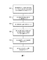
ここで図1〜図3Bを参照すると、フォームドレッシング8の実施形態およびこのようなドレッシングの製造方法が示されている。
Referring now to FIGS. 1-3B, an embodiment of a
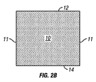
図2Aおよび図2Bは、第1の面12、第2の面14、側面11、および縁部13を有する網状連続気泡フォーム部材10の斜視図および側面図を示す。フォーム部材10は、直方柱または円柱を含む任意の好適な形状であってもよい。特定の用途では、フォーム部材10は、それを挿入しようとする創傷の形状に応じて、深さを有する正多角形または非正多角形(irregular polygon)を構成してもよい。当業者には、添付の図面中のフォーム部材10の寸法は、分かり易くするために誇張されていることが分かるであろう。
2A and 2B show perspective and side views of a reticulated open
網状連続気泡フォームは網状の微細構造を有し、独立気泡があったとしても僅かである。特定の実施形態では、気孔率は95%〜98%の範囲であってもよいが、それより気孔率の低いまたは気孔率の高いフォームを使用してもよい。特定の実施形態では、フォーム部材10は、ポリウレタン−ポリエステルまたはポリウレタン−ポリエーテルなどのポリウレタン;ポリプロピレン(PP)またはポリエチレン(PE)などのポリオレフィン;シリコーンポリマー;ポリ塩化ビニル;ポリアミド;ポリエステル;ポリアクリレート;スチレン−ブテン−スチレン(SBS)またはスチレン−エチレン−ブテン−スチレン(SEBS)などの熱可塑性エラストマー;ポリエーテル−アミドブロック共重合体(PEBAX);スチレンブタジエンゴム(SBR)などのエラストマー;エチレンプロピレンゴム(EPR);エチレンプロピレンジエン変性ゴム(EPDM);天然ゴム(NR);エチレン酢酸ビニル(EVA);ポリビニルアルコール(PVOH);ポリビニルアセタール;またはポリビニルブチラール(PVB)を含んでもよい。さらに、フォーム部材10は、生体吸収性ポリマーを含んでもよく、その例としては、ポリ乳酸、ポリラクチド(PLA)、ポリグリコール酸、ポリグリコリド(PGA)、およびポリカプロラクトン(PCL)が挙げられる。網状連続気泡フォームの製造方法は周知である。網状連続気泡フォームは、Kinetic Concepts,Inc.,San Antonio,TX,<www.kci1.com>,1−800−275−4524を含む、様々な供給元から市販されている。
Reticulated open cell foam has a reticulated microstructure, with few, if any, closed cells. In certain embodiments, the porosity may range from 95% to 98%, but lower or higher porosity foams may be used. In certain embodiments, the
図2Aおよび図2Bに示す実施形態では、フォーム部材10の第1の面12、第2の面14、および側面11は仕上げが施されていない。換言すれば、網状気泡は、フォーム部材の全面に延びている。特定の用途では、これらの仕上げが施されていない面は、創傷部位に陰圧を印加することを可能にし、肉芽組織がフォーム部材に侵入することを促進するが、これは創傷の性質によっては望ましいことがある。しかし、他の用途では、たとえ創傷部位に陰圧を提供することが望ましくても、フォーム部材中に肉芽組織が形成すると、治癒過程が複雑になり、妨げられることがある。より詳細に後述するように、肉芽組織の侵入が望ましい場合、特定の面を仕上げが施されていないままにしておいてもよい。
In the embodiment shown in FIGS. 2A and 2B, the
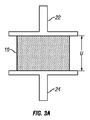
ここで図3Aおよび図3Bを参照すると、非圧縮厚みUを有するフォーム部材10が、プレス機(図示せず)の第1の熱板22と第2の熱板24との間に概略的に示されている。好適なプレス機は、Carver Press,Wabash,IN <www.carverpress.com>を含む、多くの供給元から市販されている。第1の熱板22、第2の熱板24、またはその両方を指定温度に加熱することが可能であってもよい。図示した実施形態では、第1の熱板22は指定温度に加熱される。特定の実施形態では、温度は、使用するフォームにより160℃〜180℃の範囲であってもよい。フォーム部材10は、第1の面12が第1の熱板22に面し、第2の面14が第2の熱板24に面するように、プレス機内に配置される。熱板22、24を合わせて、フォーム部材10を圧縮厚みCになるまで圧縮する。フォーム部材10の圧縮厚みCは、非圧縮厚みUの何分の1かである。特定の実施形態では、圧縮厚みCは、非圧縮厚みUの10分の1、9分の1、8分の1、7分の1、6分の1、または5分の1未満であってもよい。
Referring now to FIGS. 3A and 3B, a
多孔質フィルム層16は、フォーム部材に熱と圧力を印加することにより形成され;このような熱と圧力の印加は、「フェルト化」として知られることがある。多孔質フィルム層16は、「フェルト化された層」として知られることがある。このような方法では、フォーム部材10は、指定時間、第1の熱板22と第2の熱板24との間に圧縮位置で保持される。特定の実施形態では、時間は15分〜30分の範囲であるが、時間は、フォーム部材10に使用される材料により、それより長くてもまたは短くてもよい。一般に、熱板の温度が低いほど、フォーム部材10を圧縮状態に保持する時間を長くしなければならない。熱板を過熱すると、または圧力を印加する時間が長すぎると、フォーム部材10を炭化させるまたは焼損することにより、フォーム部材10を損傷するおそれがある。
The
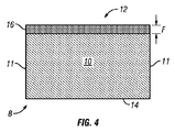
指定時間が経過した後、フォーム部材10をプレス機から取り出すことができる。図4に示すように、圧力および熱により、第1の面12に厚みFの多孔質フィルム層16が形成されることになる。多孔質フィルム層16は、フォーム部材10と一体になっている。換言すれば、多孔質フィルム層16とフォーム部材10は、単一の単位構造体(single unitary body)を形成する。多孔質フィルム層16は、図示する実施形態の第2の面14などの任意の仕上げが施されていない面またはフェルト化されていない面より比較的平滑になる。さらに、多孔質フィルム層16の細孔は、フォーム部材10全体にわたるまたは任意のフェルト化されていない側の細孔よりかなり小さい。
After the specified time has elapsed, the
特定の実施形態では、フォーム部材10の第2の面14に多孔質フィルム層を形成することが望ましい場合がある。当業者には、第1の面12ならびに第2の面14に多孔質フィルム層を形成することが可能であることが分かるであろう。多孔質フィルム層16の形成方法は、フォーム部材10を圧縮する前に両方の熱板を加熱するステップ、または、まず一方側を圧縮および加熱した後、他方側を圧縮および加熱するステップを含む。このような実施形態では、第2の面14に形成される多孔質フィルム層は、フォーム部材10と一体になっている。即ち、第2の面14に後で形成される多孔質フィルムとフォーム部材10は、単一の単位構造体を構成する。
In certain embodiments, it may be desirable to form a porous film layer on the
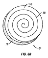
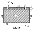
図5A〜図6Bに、創傷インサート8の様々な実施形態の斜視図および側面図を示す。創傷インサート8の第1の面12は、縁部13で側面11と交差する多孔質フィルム層16、ならびに1つ以上のチャネル18を備える。チャネル18は、直線形、曲線形、千鳥形、螺旋形、円形、または任意の奇抜な形状を含む、様々な形状を取ってもよい。図5Aに示すように、チャネル18は縁部13まで延びてもよく、または第1の面12で自己完結していてもよい。チャネル18の正確な形状は、創傷部位で最適な流体除去または流体灌注が行われるように構成されていてもよい。図6Aおよび図6Bに示すように、チャネル18の深さは、フィルム層16の厚みFにほぼ等しくてもよい。他の実施形態では、チャネル18の深さは、フィルム層16の厚みFより大きくてもよい。さらに他の実施形態では、チャネル18の深さはフィルム層16の厚みFより小さくてもよい。
5A-6B show perspective and side views of various embodiments of the
特定の実施形態では、チャネル18は、多孔質フィルム層16の一部を除去することにより、第1の面12に形成されてもよい。幾つかの実施形態では、多孔質フィルム層16の一部は、レーザーカッター(図示せず)で除去されてもよい。一例では、CADプログラムで所望のチャネルパターンを描く。チャネルパターンをコンピュータ制御レーザーカッターに伝送した後、そのレーザーカッターで創傷インサート8の多孔質フィルム層16にレーザービームを照射してもよい。他の材料除去方法の代わりにレーザーカッターを使用する利点は、レーザーの焦点深度の調節が容易であり、従ってチャネル18の深さを正確に制御できることである。レーザーは、多孔質フィルム層16からのみ材料を除去しフォーム部材10からは材料を除去しないように調節することを比較的容易に行うことができる。さらに、焦点深度が調節可能なレーザーは、異なる深さを有するチャネル18を比較的容易に形成することができ:例えば、幾つかのチャネル18の深さを多孔質フィルム層16の厚みFに等しくすることができ、他のチャネル18の深さをFより大きくすることができる。しかし、他の材料除去方法を使用してもよい。例えば、ウォータージェットカッター、ダイプレス、またはエッチングを使用して、多孔質フィルム層から材料を除去してもよい。
In certain embodiments, the
成形などの他の方法でチャネル18を形成してもよい。加熱および圧縮ステップで、所望のチャネルパターンを有する金型を一方または両方の熱板に連結してもよい。特定の実施形態では、金型を使用すると、チャネル18内に多孔質フィルムが形成されることが防止される。他の実施形態では、チャネル18は多孔質フィルムの層16を備えてもよい。
The
図6Aおよび図6Bを再度参照すると、創傷インサートの断面図が示されている。図6Aに示すように、幾つかの実施形態では、側面11は仕上げが施されていないため、網状連続気泡フォーム部材10が露出している。図6Bに示すように、他の実施形態では、側面11はシールまたは縫目15で仕上げが施されている。側面11または第2の面14は、所望の用途に応じて、仕上げが施されていてもまたは仕上げが施されていなくてもよい。側面11または面14を仕上げが施されていないままにしておくと、フォーム部材10への肉芽組織の侵入が促進される可能性がある。側面11または面14を封止もしくは縫着するまたは他の方法で仕上げを施すと、このような組織の侵入が防止される。肉芽組織の侵入は望ましい場合もあるが、望ましくない場合もある。
Referring again to FIGS. 6A and 6B, a cross-sectional view of the wound insert is shown. As shown in FIG. 6A, in some embodiments, the
ここで図7を参照すると、創傷インサート8は創傷治療システム30の一部として示されている。図示する実施形態では、創傷インサート8は、患者(図示せず)の創傷50内に、多孔質フィルム層16およびチャネル18を備える第1の面12が創傷面52に面するように配置された状態で示されている。他の実施形態では、創傷インサート8は、例えば、第2の面14に2つ以上の多孔質フィルム層16が配置されていてもよく;これらの追加の(1つ以上の)多孔質フィルム層16はチャネル18を備えても、または備えていなくてもよい。
Referring now to FIG. 7, the
ドレープ32は、創傷インサート8がドレープ32と創傷50との間に位置するように、創傷50と創傷インサート8を覆うように配置される。ドレープ32は、患者の皮膚54に連結される。創傷インサート8は導管36で創傷治療装置42に連結される。装置42は、導管36を通して創傷インサート8に陰圧を印加するように構成された真空源を備えてもよい。装置42は、導管36を通して創傷インサート8に流体を送達するように構成された流体源をさらに備えてもよい。例えば、装置42は、導管36を通して創傷インサート8に流体を圧送するように構成されたポンプを備えてもよい。このような流体の例としては、薬液、抗菌液、または洗浄液が挙げられる。San Antonio,Texas,U.S.A.のKCI USA,Inc.を通しておよび/または同社から様々な創傷療法システムおよび構成要素が市販されている。
The
導管36は、1本のシングルルーメン導管(例えば、真空源および/または流体源の間で切り替えられる)を備えてもよく、または複数のシングルルーメン導管もしくは1本のマルチルーメン導管を備えてもよく、例えば、創傷インサート8への流体の送達および/または陰圧の印加を個々にまたは同時に行うことができるようになっていてもよい。または、導管36は、複数のルーメン(例えば、陰圧の印加および/または流体送達用の中心極限(central limit)と、中心ルーメンに隣接してまたはその周囲に配置される1つ以上の周囲ルーメンとを有し、ドレープ32と創傷表面52との間の圧力または陰圧を検知および/または検出するために圧力センサに周囲ルーメンを連結することができるようになっている単一の導管におけるようなもの)を備えてもよい。図示されている実施形態では、システム30は、導管36に連結されるように構成された(および、連結された状態で示されている)創傷ドレッシング接続パッド34をさらに備える。好適な接続パッド36の一例は、San Antonio,Texas,U.S.A.のKCI USA,Inc.から市販されている「V.A.C. T.R.A.C.(登録商標)Pad」である。好適なドレープ32の一例には、San Antonio,Texas,U.S.A.のKCI,Inc.(およびその関連会社)から市販されている「V.A.C.(登録商標)ドレープ」が挙げられる。
The
チャネル18は、多孔質フィルム16を通る通路と比較して抵抗が低い通路を第2の面14との間にフォーム部材10を通して提供する。従って、流体が創傷インサート8を通して灌注されるとき、流体の大部分または全部がチャネル18を通って創傷50に流入する傾向を有することになる。逆に、流体が創傷50から除去されるとき、流体の大部分または全部がチャネル18を通り、フォーム部材10を通って、導管36に流入することになる。
The
本明細書に記載のデバイス、システム、および方法の様々な例示的実施形態は、開示されている特定の形態に限定されるものではない。むしろ、それらは、特許請求の範囲に入る全ての変更形態および代替形態を含むものとする。 The various exemplary embodiments of devices, systems, and methods described herein are not limited to the specific forms disclosed. Rather, they are intended to include all modifications and alternatives that fall within the scope of the claims.
ミーンズ−プラス−ファンクションまたはステップ−プラス−ファンクションの限定がそれぞれ「〜の手段」または「〜のステップ」の語句を使用する特定の請求項に明示的に記載されない限り、請求項はこのような限定を含むことを意図しておらず、また含むものと解釈されるべきではない。 Unless a means-plus-function or step-plus-function limitation is explicitly recited in a particular claim using the phrase "means of" or "step of", respectively, the claim is such a limitation. Is not intended and should not be construed as including.
Claims (14)
網状連続気泡フォーム部材の第1の面をフェルト化し、前記第1の面から前記部材の中に延びる第1のフェルト化された層を形成するステップ;および
前記フェルト化された層に少なくとも1つのチャネルを形成するステップ;
を含むことを特徴とする方法。 In the method of manufacturing a wound insert,
Felting a first face of a reticulated open cell foam member to form a first felted layer extending from the first face into the member; and at least one in the felted layer Forming a channel;
A method comprising the steps of:
を備える創傷インサートにおいて、前記第1のフェルト化された層に少なくとも1つのチャネルが形成され、前記第1のフェルト化された層が多孔質であり、組織の侵入を抑制することを特徴とする創傷インサート。 A reticulated open cell foam member having a first felted layer on a first surface in contact with the wound bed;
A wound insert comprising: at least one channel formed in the first felted layer, wherein the first felted layer is porous and inhibits tissue invasion. Wound insert.
Applications Claiming Priority (3)
| Application Number | Priority Date | Filing Date | Title |
|---|---|---|---|
| US42340510P | 2010-12-15 | 2010-12-15 | |
| US61/423,405 | 2010-12-15 | ||
| PCT/US2011/064588 WO2012082716A2 (en) | 2010-12-15 | 2011-12-13 | Foam dressing with integral porous film |
Related Child Applications (1)
| Application Number | Title | Priority Date | Filing Date |
|---|---|---|---|
| JP2017066931A Division JP6577505B2 (en) | 2010-12-15 | 2017-03-30 | Foam dressing with integrated porous film |
Publications (1)
| Publication Number | Publication Date |
|---|---|
| JP2014506151A true JP2014506151A (en) | 2014-03-13 |
Family
ID=45390233
Family Applications (3)
| Application Number | Title | Priority Date | Filing Date |
|---|---|---|---|
| JP2013544684A Pending JP2014506151A (en) | 2010-12-15 | 2011-12-13 | Foam dressing with integrated porous film |
| JP2017066931A Expired - Fee Related JP6577505B2 (en) | 2010-12-15 | 2017-03-30 | Foam dressing with integrated porous film |
| JP2019151648A Ceased JP2020011072A (en) | 2010-12-15 | 2019-08-22 | Foam dressing with integral porous film |
Family Applications After (2)
| Application Number | Title | Priority Date | Filing Date |
|---|---|---|---|
| JP2017066931A Expired - Fee Related JP6577505B2 (en) | 2010-12-15 | 2017-03-30 | Foam dressing with integrated porous film |
| JP2019151648A Ceased JP2020011072A (en) | 2010-12-15 | 2019-08-22 | Foam dressing with integral porous film |
Country Status (8)
| Country | Link |
|---|---|
| US (4) | US8613733B2 (en) |
| EP (1) | EP2651356B1 (en) |
| JP (3) | JP2014506151A (en) |
| CN (1) | CN103501738B (en) |
| AU (1) | AU2011344028B2 (en) |
| CA (1) | CA2819882C (en) |
| TW (1) | TW201235016A (en) |
| WO (1) | WO2012082716A2 (en) |
Families Citing this family (75)
| Publication number | Priority date | Publication date | Assignee | Title |
|---|---|---|---|---|
| US9820888B2 (en) | 2006-09-26 | 2017-11-21 | Smith & Nephew, Inc. | Wound dressing |
| GB0804654D0 (en) | 2008-03-13 | 2008-04-16 | Smith & Nephew | Vacuum closure device |
| GB0808376D0 (en) | 2008-05-08 | 2008-06-18 | Bristol Myers Squibb Co | Wound dressing |
| GB0817796D0 (en) | 2008-09-29 | 2008-11-05 | Convatec Inc | wound dressing |
| GB201020236D0 (en) | 2010-11-30 | 2011-01-12 | Convatec Technologies Inc | A composition for detecting biofilms on viable tissues |
| JP6151186B2 (en) | 2010-12-08 | 2017-06-21 | コンバテック・テクノロジーズ・インコーポレイテッドConvatec Technologies Inc | Wound exudate system attachment device |
| JP5965409B2 (en) | 2010-12-08 | 2016-08-03 | コンバテック・テクノロジーズ・インコーポレイテッドConvatec Technologies Inc | Integrated system for assessing wound exudate |
| US9421132B2 (en) | 2011-02-04 | 2016-08-23 | University Of Massachusetts | Negative pressure wound closure device |
| EP3932327A1 (en) | 2011-02-04 | 2022-01-05 | University Of Massachusetts | Negative pressure wound closure device |
| CA2833232C (en) | 2011-04-15 | 2018-05-22 | University Of Massachusetts | Surgical cavity drainage and closure system |
| JP6224581B2 (en) | 2011-06-24 | 2017-11-01 | ケーシーアイ ライセンシング インコーポレイテッド | Reduced pressure dressing with tissue fixation elements |
| GB201115182D0 (en) | 2011-09-02 | 2011-10-19 | Trio Healthcare Ltd | Skin contact material |
| GB2497406A (en) | 2011-11-29 | 2013-06-12 | Webtec Converting Llc | Dressing with a perforated binder layer |
| GB201120693D0 (en) | 2011-12-01 | 2012-01-11 | Convatec Technologies Inc | Wound dressing for use in vacuum therapy |
| US9035122B2 (en) * | 2012-03-05 | 2015-05-19 | Polyremedy, Inc. | Wound dressing inhibiting lateral diffusion of absorbed exudate |
| EP2852419B1 (en) | 2012-05-22 | 2019-11-20 | Smith & Nephew plc | Wound closure device |
| JP6382185B2 (en) | 2012-05-22 | 2018-08-29 | スミス アンド ネフュー ピーエルシーSmith & Nephew Public Limited Company | Apparatus and method for wound treatment |
| US10117782B2 (en) | 2012-05-24 | 2018-11-06 | Smith & Nephew, Inc. | Devices and methods for treating and closing wounds with negative pressure |
| RU2015104581A (en) | 2012-07-16 | 2016-09-10 | Смит Энд Нефью, Инк. | DEVICE FOR CLOSING THE Wound USING NEGATIVE PRESSURE |
| CA2895896A1 (en) | 2012-12-20 | 2014-06-26 | Convatec Technologies Inc. | Processing of chemically modified cellulosic fibres |
| DE102013002497A1 (en) * | 2013-02-13 | 2014-08-14 | Paul Hartmann Ag | Bandage kit for the treatment of wound cavities |
| CA2902776C (en) | 2013-03-13 | 2023-03-07 | Smith & Nephew Inc. | Wound treatment apparatus and use thereof |
| US10159771B2 (en) | 2013-03-14 | 2018-12-25 | Smith & Nephew Plc | Compressible wound fillers and systems and methods of use in treating wounds with negative pressure |
| US8893721B2 (en) | 2013-03-15 | 2014-11-25 | Futrell Medical Corporation | Surgical drape with vapor evacuation |
| TWI494090B (en) * | 2013-05-28 | 2015-08-01 | Shen Cherng | Method for making antibacterial hemostatic dressing |
| RU2016104132A (en) | 2013-07-16 | 2017-08-21 | СМИТ ЭНД НЕФЬЮ ПиЭлСи | DEVICE FOR TREATMENT OF THE RAS |
| CN106170275B (en) | 2013-10-21 | 2021-05-07 | 史密夫和内修有限公司 | Negative pressure wound closure device |
| CN106456376B (en) | 2014-01-21 | 2020-12-15 | 史密夫及内修公开有限公司 | Wound treatment device |
| AU2015208299B2 (en) | 2014-01-21 | 2019-11-21 | Smith & Nephew Plc | Collapsible dressing for negative pressure wound treatment |
| US10898217B2 (en) * | 2014-05-09 | 2021-01-26 | Kci Licensing, Inc. | Dressing providing apertures with multiple orifice sizes for negative-pressure therapy |
| DE102014106518A1 (en) † | 2014-05-09 | 2015-11-12 | Paul Hartmann Ag | Foam wound dressing for negative pressure therapy |
| WO2015172111A1 (en) | 2014-05-09 | 2015-11-12 | Kci Licensing, Inc. | Disruptive dressing for use with negative pressure and fluid instillation |
| JP6670827B2 (en) | 2014-05-16 | 2020-03-25 | スリーエム イノベイティブ プロパティズ カンパニー | Article including porous elastomeric material with integrated elastomeric material and method of making same |
| US9770369B2 (en) | 2014-08-08 | 2017-09-26 | Neogenix, Llc | Wound care devices, apparatus, and treatment methods |
| AU2016254119A1 (en) | 2015-04-29 | 2017-10-05 | Smith & Nephew Inc. | Negative pressure wound closure device |
| CA2993653A1 (en) | 2015-07-29 | 2017-02-02 | Innovative Therapies, Inc. | Wound therapy device pressure monitoring and control system |
| US10575991B2 (en) | 2015-12-15 | 2020-03-03 | University Of Massachusetts | Negative pressure wound closure devices and methods |
| US10814049B2 (en) | 2015-12-15 | 2020-10-27 | University Of Massachusetts | Negative pressure wound closure devices and methods |
| EP3435941B1 (en) | 2016-03-30 | 2021-09-01 | ConvaTec Technologies Inc. | Detecting microbial infections in wounds |
| BR112018070238A2 (en) | 2016-03-30 | 2019-01-29 | Acib Gmbh | detection of microbial wound infection |
| FR3052649B1 (en) * | 2016-06-20 | 2020-06-12 | L'oreal | COSMETIC APPLICATOR |
| US20210093469A1 (en) * | 2016-06-23 | 2021-04-01 | American Breast Care, Lp | Cooling Cushion for Breast Form |
| KR20190026858A (en) | 2016-07-08 | 2019-03-13 | 컨바텍 테크놀러지스 인크 | Flexible negative pressure system |
| ES2912094T3 (en) | 2016-07-08 | 2022-05-24 | Convatec Technologies Inc | Fluid flow detection |
| KR20190028467A (en) | 2016-07-08 | 2019-03-18 | 컨바텍 테크놀러지스 인크 | Body fluid collecting device |
| US11135351B2 (en) | 2016-08-30 | 2021-10-05 | Smith & Nephew Plc | Systems and methods for applying reduced pressure therapy |
| EP3518847B1 (en) | 2016-09-27 | 2023-03-01 | Smith & Nephew plc | Wound closure devices with dissolvable portions |
| CA3042673A1 (en) | 2016-11-02 | 2018-05-11 | Smith & Nephew Inc. | Wound closure devices |
| WO2018226624A1 (en) | 2017-06-07 | 2018-12-13 | Kci Licensing, Inc. | Composite dressings for improved granulation and reduced maceration with negative-pressure treatment |
| CA3065379A1 (en) | 2017-06-07 | 2018-12-13 | Kci Licensing, Inc. | Systems, apparatuses, and methods for negative-pressure treatment with reduced tissue in-growth |
| WO2018226705A1 (en) * | 2017-06-07 | 2018-12-13 | Kci Licensing, Inc. | Composite dressings for improved granulation and reduced maceration with negative-pressure treatment |
| EP3634337B1 (en) | 2017-06-07 | 2023-05-24 | 3M Innovative Properties Company | Methods for manufacturing and assembling dual material tissue interface for negative-pressure therapy |
| CA3065529A1 (en) | 2017-06-07 | 2018-12-13 | Kci Licensing, Inc. | Composite dressings for improved granulation reduced maceration with negative-pressure treatment |
| CN110944607A (en) | 2017-06-07 | 2020-03-31 | 凯希特许有限公司 | Method of manufacturing and assembling a bi-material tissue interface for negative pressure therapy |
| CA3065521A1 (en) | 2017-06-07 | 2018-12-13 | Kci Licensing, Inc. | Multi-layer wound filler for extended wear time |
| US11471584B2 (en) | 2017-06-07 | 2022-10-18 | Kci Licensing, Inc. | Composite dressings for improved granulation and reduced maceration with negative-pressure treatment |
| RU2019142320A (en) | 2017-06-07 | 2021-07-09 | Кейсиай ЛАЙСЕНСИНГ, ИНК. | Peelable and In-Place Negative Pressure Therapy Dressing |
| WO2018229010A1 (en) | 2017-06-13 | 2018-12-20 | Smith & Nephew Plc | Collapsible structure and method of use |
| JP7179022B2 (en) | 2017-06-13 | 2022-11-28 | スミス アンド ネフュー ピーエルシー | Wound closure device and method of use |
| AU2018285239B2 (en) | 2017-06-14 | 2023-09-21 | Smith & Nephew Plc | Collapsible sheet for wound closure and method of use |
| CA3063859A1 (en) | 2017-06-14 | 2018-12-20 | Smith & Nephew, Inc. | Fluid removal management and control of wound closure in wound therapy |
| US11583623B2 (en) | 2017-06-14 | 2023-02-21 | Smith & Nephew Plc | Collapsible structure for wound closure and method of use |
| WO2018231874A1 (en) | 2017-06-14 | 2018-12-20 | Smith & Nephew, Inc. | Control of wound closure and fluid removal management in wound therapy |
| WO2019020544A1 (en) | 2017-07-27 | 2019-01-31 | Smith & Nephew Plc | Customizable wound closure device and method of use |
| EP3664756B1 (en) | 2017-08-07 | 2024-01-24 | Smith & Nephew plc | Wound closure device with protective layer |
| US11375923B2 (en) | 2017-08-29 | 2022-07-05 | Smith & Nephew Plc | Systems and methods for monitoring wound closure |
| CA3078733C (en) | 2017-10-27 | 2023-02-21 | Kci Licensing, Inc. | Contoured foam dressing shaped for providing negative pressure to incisions in the breast |
| CN112912042A (en) * | 2018-09-14 | 2021-06-04 | 凯希特许有限公司 | Differential collapse wound dressing |
| WO2020124038A1 (en) | 2018-12-13 | 2020-06-18 | University Of Massachusetts | Negative pressure wound closure devices and methods |
| JP7511585B2 (en) | 2019-06-03 | 2024-07-05 | コンバテック リミティド | Methods and devices for destroying and containing pathogens - Patents.com |
| EP3989897A1 (en) * | 2019-06-28 | 2022-05-04 | KCI Licensing, Inc. | Dressings with polymer delivery |
| CN110559474A (en) * | 2019-09-09 | 2019-12-13 | 苏州汇涵医用科技发展有限公司 | Liquid wound dressing, method for the production thereof and use thereof |
| US11331221B2 (en) | 2019-12-27 | 2022-05-17 | Convatec Limited | Negative pressure wound dressing |
| US11771819B2 (en) | 2019-12-27 | 2023-10-03 | Convatec Limited | Low profile filter devices suitable for use in negative pressure wound therapy systems |
| US20230310731A1 (en) * | 2020-08-21 | 2023-10-05 | Kci Manufacturing Unlimited Company | Wound interface systems with integral contact surfaces |
Citations (5)
| Publication number | Priority date | Publication date | Assignee | Title |
|---|---|---|---|---|
| JP2003521962A (en) * | 1999-04-09 | 2003-07-22 | ケーシーアイ ライセンシング インコーポレイテッド | Wound treatment device |
| US20090287129A1 (en) * | 2004-04-13 | 2009-11-19 | Boehringer Technologies, L.P. | Method of treating a wound utilizing suction |
| WO2009158124A1 (en) * | 2008-05-30 | 2009-12-30 | Kci Licensing, Inc. | Reduced-pressure surgical wound treatment systems and methods |
| WO2010033613A1 (en) * | 2008-09-18 | 2010-03-25 | Kci Licensing, Inc. | Laminar dressings, systems, and methods for applying reduced pressure at a tissue site |
| JP2010516387A (en) * | 2007-01-25 | 2010-05-20 | ケーシーアイ ライセンシング インコーポレイテッド | Biocompatible wound dressing |
Family Cites Families (141)
| Publication number | Priority date | Publication date | Assignee | Title |
|---|---|---|---|---|
| US1355846A (en) | 1920-02-06 | 1920-10-19 | David A Rannells | Medical appliance |
| US2547758A (en) | 1949-01-05 | 1951-04-03 | Wilmer B Keeling | Instrument for treating the male urethra |
| US2632443A (en) | 1949-04-18 | 1953-03-24 | Eleanor P Lesher | Surgical dressing |
| GB692578A (en) | 1949-09-13 | 1953-06-10 | Minnesota Mining & Mfg | Improvements in or relating to drape sheets for surgical use |
| US2682873A (en) | 1952-07-30 | 1954-07-06 | Johnson & Johnson | General purpose protective dressing |
| NL189176B (en) | 1956-07-13 | 1900-01-01 | Hisamitsu Pharmaceutical Co | PLASTER BASED ON A SYNTHETIC RUBBER. |
| US2969057A (en) | 1957-11-04 | 1961-01-24 | Brady Co W H | Nematodic swab |
| US3066672A (en) | 1960-09-27 | 1962-12-04 | Jr William H Crosby | Method and apparatus for serial sampling of intestinal juice |
| US3367332A (en) | 1965-08-27 | 1968-02-06 | Gen Electric | Product and process for establishing a sterile area of skin |
| US3520300A (en) | 1967-03-15 | 1970-07-14 | Amp Inc | Surgical sponge and suction device |
| US3568675A (en) | 1968-08-30 | 1971-03-09 | Clyde B Harvey | Fistula and penetrating wound dressing |
| US3682180A (en) | 1970-06-08 | 1972-08-08 | Coilform Co Inc | Drain clip for surgical drain |
| BE789293Q (en) | 1970-12-07 | 1973-01-15 | Parke Davis & Co | MEDICO-SURGICAL DRESSING FOR BURNS AND SIMILAR LESIONS |
| US3826254A (en) | 1973-02-26 | 1974-07-30 | Verco Ind | Needle or catheter retaining appliance |
| DE2527706A1 (en) | 1975-06-21 | 1976-12-30 | Hanfried Dr Med Weigand | DEVICE FOR THE INTRODUCTION OF CONTRAST AGENTS INTO AN ARTIFICIAL INTESTINAL OUTLET |
| DE2640413C3 (en) * | 1976-09-08 | 1980-03-27 | Richard Wolf Gmbh, 7134 Knittlingen | Catheter monitor |
| NL7710909A (en) | 1976-10-08 | 1978-04-11 | Smith & Nephew | COMPOSITE STRAPS. |
| GB1562244A (en) | 1976-11-11 | 1980-03-05 | Lock P M | Wound dressing materials |
| US4080970A (en) | 1976-11-17 | 1978-03-28 | Miller Thomas J | Post-operative combination dressing and internal drain tube with external shield and tube connector |
| US4139004A (en) | 1977-02-17 | 1979-02-13 | Gonzalez Jr Harry | Bandage apparatus for treating burns |
| US4184510A (en) | 1977-03-15 | 1980-01-22 | Fibra-Sonics, Inc. | Valued device for controlling vacuum in surgery |
| US4165748A (en) | 1977-11-07 | 1979-08-28 | Johnson Melissa C | Catheter tube holder |
| US4256109A (en) | 1978-07-10 | 1981-03-17 | Nichols Robert L | Shut off valve for medical suction apparatus |
| SE414994B (en) | 1978-11-28 | 1980-09-01 | Landstingens Inkopscentral | VENKATETERFORBAND |
| GB2047543B (en) | 1978-12-06 | 1983-04-20 | Svedman Paul | Device for treating tissues for example skin |
| US4266545A (en) | 1979-04-06 | 1981-05-12 | Moss James P | Portable suction device for collecting fluids from a closed wound |
| US4284079A (en) | 1979-06-28 | 1981-08-18 | Adair Edwin Lloyd | Method for applying a male incontinence device |
| US4261363A (en) | 1979-11-09 | 1981-04-14 | C. R. Bard, Inc. | Retention clips for body fluid drains |
| US4569348A (en) | 1980-02-22 | 1986-02-11 | Velcro Usa Inc. | Catheter tube holder strap |
| WO1981002516A1 (en) | 1980-03-11 | 1981-09-17 | E Schmid | Cushion for holding an element of grafted skin |
| US4297995A (en) | 1980-06-03 | 1981-11-03 | Key Pharmaceuticals, Inc. | Bandage containing attachment post |
| US4333468A (en) | 1980-08-18 | 1982-06-08 | Geist Robert W | Mesentery tube holder apparatus |
| US4465485A (en) | 1981-03-06 | 1984-08-14 | Becton, Dickinson And Company | Suction canister with unitary shut-off valve and filter features |
| US4392853A (en) | 1981-03-16 | 1983-07-12 | Rudolph Muto | Sterile assembly for protecting and fastening an indwelling device |
| US4373519A (en) | 1981-06-26 | 1983-02-15 | Minnesota Mining And Manufacturing Company | Composite wound dressing |
| US4392858A (en) | 1981-07-16 | 1983-07-12 | Sherwood Medical Company | Wound drainage device |
| US4419097A (en) | 1981-07-31 | 1983-12-06 | Rexar Industries, Inc. | Attachment for catheter tube |
| AU550575B2 (en) | 1981-08-07 | 1986-03-27 | Richard Christian Wright | Wound drainage device |
| SE429197B (en) | 1981-10-14 | 1983-08-22 | Frese Nielsen | SAR TREATMENT DEVICE |
| DE3146266A1 (en) | 1981-11-21 | 1983-06-01 | B. Braun Melsungen Ag, 3508 Melsungen | COMBINED DEVICE FOR A MEDICAL SUCTION DRAINAGE |
| US4551139A (en) | 1982-02-08 | 1985-11-05 | Marion Laboratories, Inc. | Method and apparatus for burn wound treatment |
| US4475909A (en) | 1982-05-06 | 1984-10-09 | Eisenberg Melvin I | Male urinary device and method for applying the device |
| DE3361779D1 (en) | 1982-07-06 | 1986-02-20 | Dow Corning | Medical-surgical dressing and a process for the production thereof |
| NZ206837A (en) | 1983-01-27 | 1986-08-08 | Johnson & Johnson Prod Inc | Thin film adhesive dressing:backing material in three sections |
| US4548202A (en) | 1983-06-20 | 1985-10-22 | Ethicon, Inc. | Mesh tissue fasteners |
| US4540412A (en) | 1983-07-14 | 1985-09-10 | The Kendall Company | Device for moist heat therapy |
| US4543100A (en) | 1983-11-01 | 1985-09-24 | Brodsky Stuart A | Catheter and drain tube retainer |
| US4525374A (en) | 1984-02-27 | 1985-06-25 | Manresa, Inc. | Treating hydrophobic filters to render them hydrophilic |
| GB2157958A (en) | 1984-05-03 | 1985-11-06 | Ernest Edward Austen Bedding | Ball game net support |
| US4897081A (en) | 1984-05-25 | 1990-01-30 | Thermedics Inc. | Percutaneous access device |
| US5215522A (en) | 1984-07-23 | 1993-06-01 | Ballard Medical Products | Single use medical aspirating device and method |
| GB8419745D0 (en) | 1984-08-02 | 1984-09-05 | Smith & Nephew Ass | Wound dressing |
| US4872450A (en) | 1984-08-17 | 1989-10-10 | Austad Eric D | Wound dressing and method of forming same |
| US4826494A (en) | 1984-11-09 | 1989-05-02 | Stryker Corporation | Vacuum wound drainage system |
| US4655754A (en) | 1984-11-09 | 1987-04-07 | Stryker Corporation | Vacuum wound drainage system and lipids baffle therefor |
| US4605399A (en) | 1984-12-04 | 1986-08-12 | Complex, Inc. | Transdermal infusion device |
| US5037397A (en) | 1985-05-03 | 1991-08-06 | Medical Distributors, Inc. | Universal clamp |
| US4640688A (en) | 1985-08-23 | 1987-02-03 | Mentor Corporation | Urine collection catheter |
| US4710165A (en) | 1985-09-16 | 1987-12-01 | Mcneil Charles B | Wearable, variable rate suction/collection device |
| US4758220A (en) | 1985-09-26 | 1988-07-19 | Alcon Laboratories, Inc. | Surgical cassette proximity sensing and latching apparatus |
| US4733659A (en) | 1986-01-17 | 1988-03-29 | Seton Company | Foam bandage |
| EP0256060A1 (en) | 1986-01-31 | 1988-02-24 | OSMOND, Roger L. W. | Suction system for wound and gastro-intestinal drainage |
| US4838883A (en) | 1986-03-07 | 1989-06-13 | Nissho Corporation | Urine-collecting device |
| JPS62281965A (en) | 1986-05-29 | 1987-12-07 | テルモ株式会社 | Catheter and catheter fixing member |
| GB8621884D0 (en) | 1986-09-11 | 1986-10-15 | Bard Ltd | Catheter applicator |
| GB2195255B (en) | 1986-09-30 | 1991-05-01 | Vacutec Uk Limited | Apparatus for vacuum treatment of an epidermal surface |
| US4743232A (en) | 1986-10-06 | 1988-05-10 | The Clinipad Corporation | Package assembly for plastic film bandage |
| DE3634569A1 (en) | 1986-10-10 | 1988-04-21 | Sachse Hans E | CONDOM CATHETER, A URINE TUBE CATHETER FOR PREVENTING RISING INFECTIONS |
| JPS63135179A (en) | 1986-11-26 | 1988-06-07 | 立花 俊郎 | Subcataneous drug administration set |
| GB8628564D0 (en) | 1986-11-28 | 1987-01-07 | Smiths Industries Plc | Anti-foaming agent suction apparatus |
| GB8706116D0 (en) | 1987-03-14 | 1987-04-15 | Smith & Nephew Ass | Adhesive dressings |
| US4787888A (en) | 1987-06-01 | 1988-11-29 | University Of Connecticut | Disposable piezoelectric polymer bandage for percutaneous delivery of drugs and method for such percutaneous delivery (a) |
| US4863449A (en) | 1987-07-06 | 1989-09-05 | Hollister Incorporated | Adhesive-lined elastic condom cathether |
| US5176663A (en) | 1987-12-02 | 1993-01-05 | Pal Svedman | Dressing having pad with compressibility limiting elements |
| US4906240A (en) | 1988-02-01 | 1990-03-06 | Matrix Medica, Inc. | Adhesive-faced porous absorbent sheet and method of making same |
| US4985019A (en) | 1988-03-11 | 1991-01-15 | Michelson Gary K | X-ray marker |
| GB8812803D0 (en) | 1988-05-28 | 1988-06-29 | Smiths Industries Plc | Medico-surgical containers |
| US4919654A (en) | 1988-08-03 | 1990-04-24 | Kalt Medical Corporation | IV clamp with membrane |
| US5000741A (en) | 1988-08-22 | 1991-03-19 | Kalt Medical Corporation | Transparent tracheostomy tube dressing |
| JPH02270874A (en) | 1989-01-16 | 1990-11-05 | Roussel Uclaf | Azabicyclo compounds and their salts, their production, pharmaceutical compound containing them and their use as remedy |
| GB8906100D0 (en) | 1989-03-16 | 1989-04-26 | Smith & Nephew | Laminates |
| US4969880A (en) | 1989-04-03 | 1990-11-13 | Zamierowski David S | Wound dressing and treatment method |
| US5100396A (en) | 1989-04-03 | 1992-03-31 | Zamierowski David S | Fluidic connection system and method |
| US5527293A (en) | 1989-04-03 | 1996-06-18 | Kinetic Concepts, Inc. | Fastening system and method |
| US5261893A (en) | 1989-04-03 | 1993-11-16 | Zamierowski David S | Fastening system and method |
| US5358494A (en) | 1989-07-11 | 1994-10-25 | Svedman Paul | Irrigation dressing |
| JP2719671B2 (en) | 1989-07-11 | 1998-02-25 | 日本ゼオン株式会社 | Wound dressing |
| US5232453A (en) | 1989-07-14 | 1993-08-03 | E. R. Squibb & Sons, Inc. | Catheter holder |
| GB2235877A (en) | 1989-09-18 | 1991-03-20 | Antonio Talluri | Closed wound suction apparatus |
| US5134994A (en) | 1990-02-12 | 1992-08-04 | Say Sam L | Field aspirator in a soft pack with externally mounted container |
| US5092858A (en) | 1990-03-20 | 1992-03-03 | Becton, Dickinson And Company | Liquid gelling agent distributor device |
| US5149331A (en) | 1991-05-03 | 1992-09-22 | Ariel Ferdman | Method and device for wound closure |
| US5278100A (en) | 1991-11-08 | 1994-01-11 | Micron Technology, Inc. | Chemical vapor deposition technique for depositing titanium silicide on semiconductor wafers |
| US5636643A (en) | 1991-11-14 | 1997-06-10 | Wake Forest University | Wound treatment employing reduced pressure |
| US5645081A (en) | 1991-11-14 | 1997-07-08 | Wake Forest University | Method of treating tissue damage and apparatus for same |
| US5279550A (en) | 1991-12-19 | 1994-01-18 | Gish Biomedical, Inc. | Orthopedic autotransfusion system |
| US5167613A (en) | 1992-03-23 | 1992-12-01 | The Kendall Company | Composite vented wound dressing |
| FR2690617B1 (en) | 1992-04-29 | 1994-06-24 | Cbh Textile | TRANSPARENT ADHESIVE DRESSING. |
| DE4306478A1 (en) * | 1993-03-02 | 1994-09-08 | Wolfgang Dr Wagner | Drainage device, in particular pleural drainage device, and drainage method |
| US6241747B1 (en) | 1993-05-03 | 2001-06-05 | Quill Medical, Inc. | Barbed Bodily tissue connector |
| US5342376A (en) | 1993-05-03 | 1994-08-30 | Dermagraphics, Inc. | Inserting device for a barbed tissue connector |
| US5344415A (en) | 1993-06-15 | 1994-09-06 | Deroyal Industries, Inc. | Sterile system for dressing vascular access site |
| US5437651A (en) | 1993-09-01 | 1995-08-01 | Research Medical, Inc. | Medical suction apparatus |
| US5466231A (en) * | 1993-11-04 | 1995-11-14 | Merocel Corporation | Laminated sponge device |
| US5549584A (en) | 1994-02-14 | 1996-08-27 | The Kendall Company | Apparatus for removing fluid from a wound |
| US5607388A (en) | 1994-06-16 | 1997-03-04 | Hercules Incorporated | Multi-purpose wound dressing |
| US5556375A (en) | 1994-06-16 | 1996-09-17 | Hercules Incorporated | Wound dressing having a fenestrated base layer |
| US5664270A (en) | 1994-07-19 | 1997-09-09 | Kinetic Concepts, Inc. | Patient interface system |
| CA2198243C (en) | 1994-08-22 | 2007-06-26 | Cesar Z. Lina | Wound drainage equipment |
| DE29504378U1 (en) | 1995-03-15 | 1995-09-14 | MTG Medizinisch, technische Gerätebau GmbH, 66299 Friedrichsthal | Electronically controlled low-vacuum pump for chest and wound drainage |
| GB9523253D0 (en) | 1995-11-14 | 1996-01-17 | Mediscus Prod Ltd | Portable wound treatment apparatus |
| US5626814A (en) * | 1995-11-20 | 1997-05-06 | Vicino; Robert K. | Method of making a self-inflating structure |
| SE505000C2 (en) * | 1996-05-14 | 1997-06-09 | Moelnlycke Ab | Wound dressing and manufacturing process therefore |
| US6135116A (en) | 1997-07-28 | 2000-10-24 | Kci Licensing, Inc. | Therapeutic method for treating ulcers |
| GB9719520D0 (en) | 1997-09-12 | 1997-11-19 | Kci Medical Ltd | Surgical drape and suction heads for wound treatment |
| AU755496B2 (en) | 1997-09-12 | 2002-12-12 | Kci Licensing, Inc. | Surgical drape and suction head for wound treatment |
| US6071267A (en) | 1998-02-06 | 2000-06-06 | Kinetic Concepts, Inc. | Medical patient fluid management interface system and method |
| US6488643B1 (en) | 1998-10-08 | 2002-12-03 | Kci Licensing, Inc. | Wound healing foot wrap |
| US6287316B1 (en) | 1999-03-26 | 2001-09-11 | Ethicon, Inc. | Knitted surgical mesh |
| US7799004B2 (en) | 2001-03-05 | 2010-09-21 | Kci Licensing, Inc. | Negative pressure wound treatment apparatus and infection identification system and method |
| US6856821B2 (en) | 2000-05-26 | 2005-02-15 | Kci Licensing, Inc. | System for combined transcutaneous blood gas monitoring and vacuum assisted wound closure |
| US6991643B2 (en) | 2000-12-20 | 2006-01-31 | Usgi Medical Inc. | Multi-barbed device for retaining tissue in apposition and methods of use |
| ES2220734T3 (en) | 2000-02-24 | 2004-12-16 | Venetec International, Inc. | UNIVERSAL FIXING SYSTEM FOR CATETER. |
| US6540705B2 (en) | 2001-02-22 | 2003-04-01 | Core Products International, Inc. | Ankle brace providing upper and lower ankle adjustment |
| US7371403B2 (en) | 2002-06-14 | 2008-05-13 | Providence Health System-Oregon | Wound dressing and method for controlling severe, life-threatening bleeding |
| US8269058B2 (en) | 2002-06-14 | 2012-09-18 | Hemcon Medical Technologies, Inc. | Absorbable tissue dressing assemblies, systems, and methods formed from hydrophilic polymer sponge structures such as chitosan |
| US7846141B2 (en) | 2002-09-03 | 2010-12-07 | Bluesky Medical Group Incorporated | Reduced pressure treatment system |
| GB0224986D0 (en) | 2002-10-28 | 2002-12-04 | Smith & Nephew | Apparatus |
| US7976519B2 (en) | 2002-12-31 | 2011-07-12 | Kci Licensing, Inc. | Externally-applied patient interface system and method |
| GB0325120D0 (en) | 2003-10-28 | 2003-12-03 | Smith & Nephew | Apparatus with actives |
| GB0325126D0 (en) | 2003-10-28 | 2003-12-03 | Smith & Nephew | Apparatus with heat |
| US7909805B2 (en) | 2004-04-05 | 2011-03-22 | Bluesky Medical Group Incorporated | Flexible reduced pressure treatment appliance |
| US8529548B2 (en) | 2004-04-27 | 2013-09-10 | Smith & Nephew Plc | Wound treatment apparatus and method |
| MX2008000893A (en) * | 2005-07-19 | 2008-04-04 | Dow Global Technologies Inc | Frothed thermoplastic foam and its uses in sanitary applications. |
| PL2826450T3 (en) * | 2006-04-07 | 2020-06-15 | Absorbent article having nonwoven lateral zones | |
| US8021347B2 (en) | 2008-07-21 | 2011-09-20 | Tyco Healthcare Group Lp | Thin film wound dressing |
| US8247466B2 (en) * | 2008-04-21 | 2012-08-21 | Fxi, Inc. | Variable felted polyurethane foams for sponges and wipes |
| US8007481B2 (en) | 2008-07-17 | 2011-08-30 | Tyco Healthcare Group Lp | Subatmospheric pressure mechanism for wound therapy system |
| US8251979B2 (en) | 2009-05-11 | 2012-08-28 | Tyco Healthcare Group Lp | Orientation independent canister for a negative pressure wound therapy device |
| US8216198B2 (en) | 2009-01-09 | 2012-07-10 | Tyco Healthcare Group Lp | Canister for receiving wound exudate in a negative pressure therapy system |
| EP2525955B1 (en) | 2010-01-20 | 2019-06-12 | KCI Licensing, Inc. | Foam wound inserts with regions of higher and lower densities, wound dressings, and methods |
-
2011
- 2011-12-12 US US13/316,997 patent/US8613733B2/en active Active
- 2011-12-13 WO PCT/US2011/064588 patent/WO2012082716A2/en active Application Filing
- 2011-12-13 AU AU2011344028A patent/AU2011344028B2/en not_active Ceased
- 2011-12-13 JP JP2013544684A patent/JP2014506151A/en active Pending
- 2011-12-13 CA CA2819882A patent/CA2819882C/en active Active
- 2011-12-13 EP EP11799592.8A patent/EP2651356B1/en active Active
- 2011-12-13 CN CN201180058937.9A patent/CN103501738B/en not_active Expired - Fee Related
- 2011-12-15 TW TW100146603A patent/TW201235016A/en unknown
-
2013
- 2013-11-13 US US14/015,385 patent/US9289328B2/en active Active
-
2016
- 2016-02-15 US US15/043,974 patent/US10517766B2/en not_active Expired - Fee Related
-
2017
- 2017-03-30 JP JP2017066931A patent/JP6577505B2/en not_active Expired - Fee Related
-
2019
- 2019-08-22 JP JP2019151648A patent/JP2020011072A/en not_active Ceased
- 2019-11-22 US US16/692,770 patent/US20200085630A1/en not_active Abandoned
Patent Citations (5)
| Publication number | Priority date | Publication date | Assignee | Title |
|---|---|---|---|---|
| JP2003521962A (en) * | 1999-04-09 | 2003-07-22 | ケーシーアイ ライセンシング インコーポレイテッド | Wound treatment device |
| US20090287129A1 (en) * | 2004-04-13 | 2009-11-19 | Boehringer Technologies, L.P. | Method of treating a wound utilizing suction |
| JP2010516387A (en) * | 2007-01-25 | 2010-05-20 | ケーシーアイ ライセンシング インコーポレイテッド | Biocompatible wound dressing |
| WO2009158124A1 (en) * | 2008-05-30 | 2009-12-30 | Kci Licensing, Inc. | Reduced-pressure surgical wound treatment systems and methods |
| WO2010033613A1 (en) * | 2008-09-18 | 2010-03-25 | Kci Licensing, Inc. | Laminar dressings, systems, and methods for applying reduced pressure at a tissue site |
Also Published As
| Publication number | Publication date |
|---|---|
| US20160158068A1 (en) | 2016-06-09 |
| CN103501738A (en) | 2014-01-08 |
| TW201235016A (en) | 2012-09-01 |
| US20140058345A1 (en) | 2014-02-27 |
| JP6577505B2 (en) | 2019-09-18 |
| US9289328B2 (en) | 2016-03-22 |
| CA2819882A1 (en) | 2012-06-21 |
| US10517766B2 (en) | 2019-12-31 |
| US20120157945A1 (en) | 2012-06-21 |
| CA2819882C (en) | 2019-10-22 |
| AU2011344028B2 (en) | 2016-07-28 |
| US8613733B2 (en) | 2013-12-24 |
| WO2012082716A2 (en) | 2012-06-21 |
| JP2020011072A (en) | 2020-01-23 |
| AU2011344028A1 (en) | 2013-06-13 |
| JP2017148527A (en) | 2017-08-31 |
| EP2651356A2 (en) | 2013-10-23 |
| US20200085630A1 (en) | 2020-03-19 |
| EP2651356B1 (en) | 2022-06-15 |
| CN103501738B (en) | 2016-01-20 |
| WO2012082716A3 (en) | 2012-08-09 |
Similar Documents
| Publication | Publication Date | Title |
|---|---|---|
| JP6577505B2 (en) | Foam dressing with integrated porous film | |
| US11433175B2 (en) | Foam structure wound inserts for directional granulation | |
| US11224542B2 (en) | Foam wound inserts with regions of higher and lower densities, wound dressings, and methods | |
| CN111134779B (en) | Debridement dressings for use with negative pressure and fluid instillation | |
| US20200155359A1 (en) | Wound dressing with semi-rigid support to increase disruption using perforated dressing and negative pressure wound therapy | |
| TWI542332B (en) | Negative pressure wound treatment group, wound dressings and wound dressings | |
| JP6075726B2 (en) | Foam wound insert, wound dressing, and method having high density and low density areas | |
| TW201136625A (en) | Epithelialization methods, dressings, and systems |
Legal Events
| Date | Code | Title | Description |
|---|---|---|---|
| A621 | Written request for application examination |
Free format text: JAPANESE INTERMEDIATE CODE: A621 Effective date: 20141205 |
|
| A977 | Report on retrieval |
Free format text: JAPANESE INTERMEDIATE CODE: A971007 Effective date: 20150514 |
|
| A131 | Notification of reasons for refusal |
Free format text: JAPANESE INTERMEDIATE CODE: A131 Effective date: 20150707 |
|
| A521 | Request for written amendment filed |
Free format text: JAPANESE INTERMEDIATE CODE: A523 Effective date: 20151001 |
|
| A131 | Notification of reasons for refusal |
Free format text: JAPANESE INTERMEDIATE CODE: A131 Effective date: 20160405 |
|
| A521 | Request for written amendment filed |
Free format text: JAPANESE INTERMEDIATE CODE: A523 Effective date: 20160606 |
|
| A02 | Decision of refusal |
Free format text: JAPANESE INTERMEDIATE CODE: A02 Effective date: 20161206 |