JP2014505558A - System and method for cardiac resynchronization therapy regulation parameter generation using ventricular excitation simulation and surface ECG measurements - Google Patents
System and method for cardiac resynchronization therapy regulation parameter generation using ventricular excitation simulation and surface ECG measurements Download PDFInfo
- Publication number
- JP2014505558A JP2014505558A JP2013552573A JP2013552573A JP2014505558A JP 2014505558 A JP2014505558 A JP 2014505558A JP 2013552573 A JP2013552573 A JP 2013552573A JP 2013552573 A JP2013552573 A JP 2013552573A JP 2014505558 A JP2014505558 A JP 2014505558A
- Authority
- JP
- Japan
- Prior art keywords
- ventricular
- cardiac
- basic
- model
- qrs
- Prior art date
- Legal status (The legal status is an assumption and is not a legal conclusion. Google has not performed a legal analysis and makes no representation as to the accuracy of the status listed.)
- Pending
Links
- 230000002861 ventricular Effects 0.000 title claims abstract description 141
- 238000000034 method Methods 0.000 title claims abstract description 38
- 238000009125 cardiac resynchronization therapy Methods 0.000 title claims abstract description 30
- 230000005284 excitation Effects 0.000 title claims description 28
- 238000004088 simulation Methods 0.000 title abstract description 30
- 238000005259 measurement Methods 0.000 title description 12
- 230000033228 biological regulation Effects 0.000 title description 2
- 230000000694 effects Effects 0.000 claims abstract description 69
- 230000000747 cardiac effect Effects 0.000 claims abstract description 46
- 230000000877 morphologic effect Effects 0.000 claims abstract description 14
- 230000004927 fusion Effects 0.000 claims description 37
- 231100000241 scar Toxicity 0.000 claims description 13
- 230000000638 stimulation Effects 0.000 claims description 9
- 238000007726 management method Methods 0.000 claims description 6
- 230000033764 rhythmic process Effects 0.000 claims description 6
- 238000012384 transportation and delivery Methods 0.000 claims description 4
- 230000002964 excitative effect Effects 0.000 claims description 3
- 230000001939 inductive effect Effects 0.000 claims 1
- 206010001497 Agitation Diseases 0.000 abstract description 3
- 230000002452 interceptive effect Effects 0.000 abstract 1
- 230000004913 activation Effects 0.000 description 25
- 230000002441 reversible effect Effects 0.000 description 10
- 238000004458 analytical method Methods 0.000 description 9
- 230000006854 communication Effects 0.000 description 9
- 238000004891 communication Methods 0.000 description 9
- 230000000875 corresponding effect Effects 0.000 description 9
- 238000007634 remodeling Methods 0.000 description 9
- 230000008859 change Effects 0.000 description 8
- 230000008569 process Effects 0.000 description 8
- 230000006870 function Effects 0.000 description 6
- 230000001746 atrial effect Effects 0.000 description 4
- 230000006872 improvement Effects 0.000 description 4
- 210000005240 left ventricle Anatomy 0.000 description 4
- 238000002560 therapeutic procedure Methods 0.000 description 4
- 206010019280 Heart failures Diseases 0.000 description 3
- 238000013459 approach Methods 0.000 description 3
- 230000008901 benefit Effects 0.000 description 3
- 238000012986 modification Methods 0.000 description 3
- 230000004048 modification Effects 0.000 description 3
- 230000002107 myocardial effect Effects 0.000 description 3
- 230000000737 periodic effect Effects 0.000 description 3
- 238000000718 qrs complex Methods 0.000 description 3
- 238000011002 quantification Methods 0.000 description 3
- 239000000758 substrate Substances 0.000 description 3
- 230000009471 action Effects 0.000 description 2
- 230000001105 regulatory effect Effects 0.000 description 2
- 230000035939 shock Effects 0.000 description 2
- 239000013589 supplement Substances 0.000 description 2
- 206010006578 Bundle-Branch Block Diseases 0.000 description 1
- 206010052337 Diastolic dysfunction Diseases 0.000 description 1
- 206010061216 Infarction Diseases 0.000 description 1
- 235000014676 Phragmites communis Nutrition 0.000 description 1
- 238000012300 Sequence Analysis Methods 0.000 description 1
- 208000033774 Ventricular Remodeling Diseases 0.000 description 1
- 230000002159 abnormal effect Effects 0.000 description 1
- 230000005856 abnormality Effects 0.000 description 1
- 230000002411 adverse Effects 0.000 description 1
- 206010003119 arrhythmia Diseases 0.000 description 1
- 230000006399 behavior Effects 0.000 description 1
- 230000007175 bidirectional communication Effects 0.000 description 1
- 210000004204 blood vessel Anatomy 0.000 description 1
- 238000013184 cardiac magnetic resonance imaging Methods 0.000 description 1
- 238000013194 cardioversion Methods 0.000 description 1
- 238000012512 characterization method Methods 0.000 description 1
- 230000008602 contraction Effects 0.000 description 1
- 238000012937 correction Methods 0.000 description 1
- 230000002596 correlated effect Effects 0.000 description 1
- 238000013500 data storage Methods 0.000 description 1
- 230000003247 decreasing effect Effects 0.000 description 1
- 238000013461 design Methods 0.000 description 1
- 238000001514 detection method Methods 0.000 description 1
- 238000002592 echocardiography Methods 0.000 description 1
- 230000005520 electrodynamics Effects 0.000 description 1
- 238000002474 experimental method Methods 0.000 description 1
- 210000002837 heart atrium Anatomy 0.000 description 1
- 230000007574 infarction Effects 0.000 description 1
- 230000010354 integration Effects 0.000 description 1
- 210000005246 left atrium Anatomy 0.000 description 1
- 238000013507 mapping Methods 0.000 description 1
- 238000000691 measurement method Methods 0.000 description 1
- 230000007246 mechanism Effects 0.000 description 1
- 230000028161 membrane depolarization Effects 0.000 description 1
- 238000010223 real-time analysis Methods 0.000 description 1
- 230000008929 regeneration Effects 0.000 description 1
- 238000011069 regeneration method Methods 0.000 description 1
- 230000004044 response Effects 0.000 description 1
- 210000005245 right atrium Anatomy 0.000 description 1
- 210000005241 right ventricle Anatomy 0.000 description 1
- 230000035945 sensitivity Effects 0.000 description 1
- 230000002269 spontaneous effect Effects 0.000 description 1
- 238000007920 subcutaneous administration Methods 0.000 description 1
- 230000000153 supplemental effect Effects 0.000 description 1
- 238000004441 surface measurement Methods 0.000 description 1
- 230000001360 synchronised effect Effects 0.000 description 1
- 238000012546 transfer Methods 0.000 description 1
- 238000012285 ultrasound imaging Methods 0.000 description 1
- 210000002620 vena cava superior Anatomy 0.000 description 1
- 210000000596 ventricular septum Anatomy 0.000 description 1
Images


Classifications
-
- G—PHYSICS
- G16—INFORMATION AND COMMUNICATION TECHNOLOGY [ICT] SPECIALLY ADAPTED FOR SPECIFIC APPLICATION FIELDS
- G16H—HEALTHCARE INFORMATICS, i.e. INFORMATION AND COMMUNICATION TECHNOLOGY [ICT] SPECIALLY ADAPTED FOR THE HANDLING OR PROCESSING OF MEDICAL OR HEALTHCARE DATA
- G16H40/00—ICT specially adapted for the management or administration of healthcare resources or facilities; ICT specially adapted for the management or operation of medical equipment or devices
- G16H40/60—ICT specially adapted for the management or administration of healthcare resources or facilities; ICT specially adapted for the management or operation of medical equipment or devices for the operation of medical equipment or devices
-
- A—HUMAN NECESSITIES
- A61—MEDICAL OR VETERINARY SCIENCE; HYGIENE
- A61B—DIAGNOSIS; SURGERY; IDENTIFICATION
- A61B5/00—Measuring for diagnostic purposes; Identification of persons
- A61B5/24—Detecting, measuring or recording bioelectric or biomagnetic signals of the body or parts thereof
- A61B5/316—Modalities, i.e. specific diagnostic methods
- A61B5/318—Heart-related electrical modalities, e.g. electrocardiography [ECG]
- A61B5/327—Generation of artificial ECG signals based on measured signals, e.g. to compensate for missing leads
-
- A—HUMAN NECESSITIES
- A61—MEDICAL OR VETERINARY SCIENCE; HYGIENE
- A61B—DIAGNOSIS; SURGERY; IDENTIFICATION
- A61B5/00—Measuring for diagnostic purposes; Identification of persons
- A61B5/24—Detecting, measuring or recording bioelectric or biomagnetic signals of the body or parts thereof
- A61B5/316—Modalities, i.e. specific diagnostic methods
- A61B5/318—Heart-related electrical modalities, e.g. electrocardiography [ECG]
- A61B5/346—Analysis of electrocardiograms
- A61B5/349—Detecting specific parameters of the electrocardiograph cycle
-
- A—HUMAN NECESSITIES
- A61—MEDICAL OR VETERINARY SCIENCE; HYGIENE
- A61B—DIAGNOSIS; SURGERY; IDENTIFICATION
- A61B5/00—Measuring for diagnostic purposes; Identification of persons
- A61B5/48—Other medical applications
- A61B5/4836—Diagnosis combined with treatment in closed-loop systems or methods
-
- A—HUMAN NECESSITIES
- A61—MEDICAL OR VETERINARY SCIENCE; HYGIENE
- A61N—ELECTROTHERAPY; MAGNETOTHERAPY; RADIATION THERAPY; ULTRASOUND THERAPY
- A61N1/00—Electrotherapy; Circuits therefor
- A61N1/18—Applying electric currents by contact electrodes
- A61N1/32—Applying electric currents by contact electrodes alternating or intermittent currents
- A61N1/36—Applying electric currents by contact electrodes alternating or intermittent currents for stimulation
- A61N1/362—Heart stimulators
- A61N1/3627—Heart stimulators for treating a mechanical deficiency of the heart, e.g. congestive heart failure or cardiomyopathy
-
- A—HUMAN NECESSITIES
- A61—MEDICAL OR VETERINARY SCIENCE; HYGIENE
- A61N—ELECTROTHERAPY; MAGNETOTHERAPY; RADIATION THERAPY; ULTRASOUND THERAPY
- A61N1/00—Electrotherapy; Circuits therefor
- A61N1/18—Applying electric currents by contact electrodes
- A61N1/32—Applying electric currents by contact electrodes alternating or intermittent currents
- A61N1/36—Applying electric currents by contact electrodes alternating or intermittent currents for stimulation
- A61N1/362—Heart stimulators
- A61N1/365—Heart stimulators controlled by a physiological parameter, e.g. heart potential
- A61N1/36585—Heart stimulators controlled by a physiological parameter, e.g. heart potential controlled by two or more physical parameters
-
- A—HUMAN NECESSITIES
- A61—MEDICAL OR VETERINARY SCIENCE; HYGIENE
- A61N—ELECTROTHERAPY; MAGNETOTHERAPY; RADIATION THERAPY; ULTRASOUND THERAPY
- A61N1/00—Electrotherapy; Circuits therefor
- A61N1/18—Applying electric currents by contact electrodes
- A61N1/32—Applying electric currents by contact electrodes alternating or intermittent currents
- A61N1/36—Applying electric currents by contact electrodes alternating or intermittent currents for stimulation
- A61N1/362—Heart stimulators
- A61N1/365—Heart stimulators controlled by a physiological parameter, e.g. heart potential
- A61N1/36592—Heart stimulators controlled by a physiological parameter, e.g. heart potential controlled by the heart rate variability
-
- G—PHYSICS
- G16—INFORMATION AND COMMUNICATION TECHNOLOGY [ICT] SPECIALLY ADAPTED FOR SPECIFIC APPLICATION FIELDS
- G16H—HEALTHCARE INFORMATICS, i.e. INFORMATION AND COMMUNICATION TECHNOLOGY [ICT] SPECIALLY ADAPTED FOR THE HANDLING OR PROCESSING OF MEDICAL OR HEALTHCARE DATA
- G16H20/00—ICT specially adapted for therapies or health-improving plans, e.g. for handling prescriptions, for steering therapy or for monitoring patient compliance
- G16H20/30—ICT specially adapted for therapies or health-improving plans, e.g. for handling prescriptions, for steering therapy or for monitoring patient compliance relating to physical therapies or activities, e.g. physiotherapy, acupressure or exercising
-
- G—PHYSICS
- G16—INFORMATION AND COMMUNICATION TECHNOLOGY [ICT] SPECIALLY ADAPTED FOR SPECIFIC APPLICATION FIELDS
- G16H—HEALTHCARE INFORMATICS, i.e. INFORMATION AND COMMUNICATION TECHNOLOGY [ICT] SPECIALLY ADAPTED FOR THE HANDLING OR PROCESSING OF MEDICAL OR HEALTHCARE DATA
- G16H50/00—ICT specially adapted for medical diagnosis, medical simulation or medical data mining; ICT specially adapted for detecting, monitoring or modelling epidemics or pandemics
- G16H50/50—ICT specially adapted for medical diagnosis, medical simulation or medical data mining; ICT specially adapted for detecting, monitoring or modelling epidemics or pandemics for simulation or modelling of medical disorders
Landscapes
- Health & Medical Sciences (AREA)
- Life Sciences & Earth Sciences (AREA)
- Engineering & Computer Science (AREA)
- Cardiology (AREA)
- Public Health (AREA)
- Biomedical Technology (AREA)
- General Health & Medical Sciences (AREA)
- Heart & Thoracic Surgery (AREA)
- Medical Informatics (AREA)
- Biophysics (AREA)
- Animal Behavior & Ethology (AREA)
- Veterinary Medicine (AREA)
- Pathology (AREA)
- Epidemiology (AREA)
- Molecular Biology (AREA)
- Surgery (AREA)
- Physics & Mathematics (AREA)
- Primary Health Care (AREA)
- Nuclear Medicine, Radiotherapy & Molecular Imaging (AREA)
- Radiology & Medical Imaging (AREA)
- Physiology (AREA)
- Databases & Information Systems (AREA)
- Hospice & Palliative Care (AREA)
- Data Mining & Analysis (AREA)
- Business, Economics & Management (AREA)
- General Business, Economics & Management (AREA)
- Physical Education & Sports Medicine (AREA)
- Electrotherapy Devices (AREA)
- Measurement And Recording Of Electrical Phenomena And Electrical Characteristics Of The Living Body (AREA)
Abstract
各種の表面心電計(ECG)信号から得られた基礎全心電気活動モデルのような、基礎電気活動モデルを用いて、心臓植え込み型電気装置(CIED)のペーシング調整パラメータによる自動的な調整に使用する心臓再同期療法(CRT)のためのシステム及び方法を提供するものである。心室電気的非同期(ventricular electrical asynchrony)を最小化するまで、基礎モデルを、相互作用する方法で模擬のペーシング調整パラメータで修正する。最小電気非同期がその結果生じたシミュレーションに基づくペーシング調整パラメータと、心室興奮の最新モデルを生成することに使用するとともに、最新モデルをQRSグリフ形態学的フレームワーク(QRS glyph morphological framework)を使用する調節パラメータを生成することに使用する。
【選択図】図1Uses basic electrical activity models, such as basic whole-heart electrical activity models derived from various surface electrocardiograph (ECG) signals, for automatic adjustment with pacing adjustment parameters of cardiac implantable electrical devices (CIED) A system and method for cardiac resynchronization therapy (CRT) to be used is provided. The basic model is modified with simulated pacing adjustment parameters in an interactive manner until ventricular electrical asynchrony is minimized. Pacing adjustment parameters based on simulations resulting from minimal electrical asynchrony and are used to generate an updated model of ventricular excitability, and the updated model is adjusted using the QRS glyph morphological framework Used to generate parameters.
[Selection] Figure 1
Description
関連出願の相互参照
本出願は、2011年2月1日付で出願された、発明の名称“マルチサイトペーシング(multisite pacing)療法の際の心室興奮波面融合(ventricular activation wavefront fusion)を自動生成するためのシステム及び方法を伴う心室興奮シミュレーションと表面ECG測定値の統合”と題する米国仮出願61/462366号の優先権の利益を享受する。
CROSS REFERENCE TO RELATED APPLICATIONS This application is for the purpose of automatically generating the ventricular activation wavefront fusion in the title of the invention "multisite pacing therapy" filed on February 1, 2011. Enjoy the priority benefit of US Provisional Application No. 61/462366, entitled “Integration of Ventricular Excitement Simulation and Surface ECG Measurements with the System and Method of”.
本発明は、心調律管理(cardiac rhythm management)のためのシステム及び方法に関する。特に、本発明は、全体的な心臓の電気的活動をシミュレーションし取得されたモデルのような、心臓の電気的活動をシミュレーションし取得されたモデルに関連してペーシング調整パラメータ(pacing control parameter)の調整が自動的に行われる心臓再同期療法(cardiac resynchronization therapy)を行うためのシステム及び方法に関する。 The present invention relates to a system and method for cardiac rhythm management. In particular, the present invention relates to a pacing control parameter in connection with a model obtained by simulating cardiac electrical activity, such as a model obtained by simulating overall cardiac electrical activity. The present invention relates to a system and method for performing cardiac resynchronization therapy in which coordination is performed automatically.
脚ブロック(bundle branch block)による左心室伝導遅延(left ventricular conduction delay)は、収縮及びストレッチに極地的な異質性(heterogeneity)、あるいはポンプ機能を下げ、増加したチャンバ容積のような負の左心室リモデリングを刺激する非同期(asynchrony)を引き起こす。実験モデルでは、左心室の電気的活性化、心臓の力学、及びリモデリングの間の直接的な関連性が証明されている。また、非同期心不全に対する心臓再同期療法(cardiac resynchronization therapy; CRT)または二心室ペーシング(biventricular pacing)と呼ばれるマルチサイトペーシング(multisite pacing)の概念的基礎は、収縮性非同期性を減少させ、チャンバメカニクスを改善する心室伝導遅延(ventricular conduction delay)を最小限に抑えることである。電気力学的活動の再同期化は、心室容積減少を特徴とする、いわゆる逆リモデリング(reverse remodeling)と、増加された心室駆出分画(ventricular ejection fraction)を特徴とする改善されたポンプ機能を誘導する。逆リモデリングは、減少された心不全の羅患率及び死亡率に関係する。しかしながら、1/3までの患者は、次に述べるCRTでも改善されない。 Left ventricular conduction delay due to a bundle branch block is a negative left ventricle such as increased heterogeneity in contraction and stretch, or reduced pump function and increased chamber volume Causes asynchrony to stimulate remodeling. Experimental models have demonstrated a direct link between left ventricular electrical activation, cardiac mechanics, and remodeling. In addition, the conceptual basis of multisite pacing, called cardiac resynchronization therapy (CRT) or biventricular pacing for asynchronous heart failure, reduces contractile asynchrony and reduces chamber mechanics. The improvement is to minimize ventricular conduction delay. Resynchronization of electrodynamic activity is improved pump function characterized by so-called reverse remodeling, characterized by decreased ventricular volume, and increased ventricular ejection fraction To induce. Reverse remodeling is associated with reduced heart failure morbidity and mortality. However, up to 1/3 of patients cannot be improved by the CRT described below.
非同期心不全に対するマルチサイトペーシング(multisite pacing)に応じての逆容積リモデリングの並進機構(translational mechanism)は、ペース調整12−リード表面心電図上で明らかである心室興奮波面融合(ventricular activation wavefront fusion)である。基礎基質条件(baseline substrate condition)に関係なく、心室興奮波面融合が存在すると、逆リモデリングの可能性の増加が予測される一方、波面融合が存在しないとリモデリングの可能性の減少が予測される。 The translational mechanism of reverse volume remodeling in response to multisite pacing for asynchronous heart failure is pace-regulated 12-ventricular activation wavefront fusion that is evident on the lead surface electrocardiogram. is there. Regardless of the baseline substrate condition, the presence of ventricular excitation wavefront fusion is expected to increase the likelihood of reverse remodeling, while the absence of wavefront fusion is expected to reduce the likelihood of remodeling. The
高い心筋瘢痕容積(myocardial scar volume)または少量の心室伝導遅延のような不利な基質条件は、ペーシング技術によって変更することは出来ない。対照的に、ペーシング戦略は、心室興奮を変更するために容易に適用することができ、このような処方は、心臓植込み型電気装置(CIED)を有する完全外来患者に対し自動的に実施することができる。最近の実験では、CIED患者の3分の2のみが、従来のCRTの際に、心室興奮波面融合のペーシング調整された表面ECG証拠を有することが明らかになった。これは、従来のCRTペーシングにも関わらず、心室伝導遅延の補正失敗が、容積リモデリング非応答(volumetric remodeling nonresponse)の大きな原因となり得ることを意味する。 Adverse substrate conditions such as high myocardial scar volume or small amounts of ventricular conduction delay cannot be altered by pacing techniques. In contrast, pacing strategies can be easily applied to alter ventricular excitement, and such prescriptions should be performed automatically for fully outpatients with cardiac implantable electrical devices (CIED) Can do. Recent experiments revealed that only two-thirds of CIED patients have pacing-adjusted surface ECG evidence of ventricular excitation wavefront fusion during conventional CRT. This means that despite conventional CRT pacing, ventricular conduction delay correction failure can be a major cause of volumetric remodeling nonresponse.
CRT用ペーシングコントロールシステムの自動または半自動調整における既存のCIEDアプローチの限界は、それらが、任意の臨床結果による測定値、特に逆容積リモデリングにおける改善とは相関していない限られた装置による測定値にのみに依存しているということである。 The limitations of existing CIED approaches in automatic or semi-automatic adjustment of pacing control systems for CRT are that they are measured by any clinical outcome, especially by limited instruments that are not correlated with improvements in reverse volume remodeling It depends on only.
したがって、全体的な心室興奮パターンにより特徴付けられ、心室興奮波面融合(ventricular activation wavefront fusion)により正確に基づく患者独自の心臓再同期療法(cardiac resynchronization therapy)のペーシング調整パラメータ(pacing control parameter)を生み出すシステム及び方法を提供することが望ましい。 Thus, the patient's unique cardiac resynchronization therapy pacing control parameter is characterized by the overall ventricular excitation pattern and accurately based on ventricular activation wavefront fusion. It would be desirable to provide a system and method.
本発明は、さまざまな表面心電計(ECG)信号由来の基礎全心電気活動モデルのような基礎心臓電気活動モデルが、提供された心臓植え込み型電気装置(CIED)のペーシング調整パラメータを自動調整するために使用される、心臓再同期療法(CRT)のためのシステム及び方法を提供することによって、前記の欠点を克服するものである。前記基礎モデルは、心室電気的非同期(ventricular electrical asynchrony)を最小化するまで、繰り返し模擬のペーシング調整パラメータ(pacing control parameter)が修正される。最小限の心室電気的非同期(ventricular electrical asynchrony)を結論とする模擬の前記ペーシング調整パラメータ(pacing control parameter)は、心室興奮のモデルを生成することに使用されるとともに、この最新モデルは、QRSグリフ形態学的フレームワーク(QRS glyph morphological framework)を使用するCIEDのための調節パラメータを生み出すことに使用される。 The present invention provides a basic cardiac electrical activity model, such as a basic total cardiac electrical activity model derived from various surface electrocardiograph (ECG) signals, that automatically adjusts the pacing adjustment parameters of the provided cardiac implantable electrical device (CIED) It overcomes the aforementioned drawbacks by providing a system and method for cardiac resynchronization therapy (CRT) that is used to do so. The basic model is modified with repeated simulated pacing control parameters until ventricular electrical asynchrony is minimized. The simulated pacing control parameter, which concludes minimal ventricular electrical asynchrony, is used to generate a model of ventricular excitation, and this latest model is a QRS glyph. Used to generate regulatory parameters for CIED using the QRS glyph morphological framework.
本発明の第1の特徴は、心調律管理(cardiac rhythm management)を備えた患者の心臓に心臓再同期療法(cardiac resynchronization therapy)を届けるための方法を提供する。患者の心臓における基礎心臓電気活動を代表する信号は、心電計の表面誘導電極(surface-lead electrodes)の使用により得られ、基礎心室性伝導モデル(baseline model of ventricular conduction)は、これらの信号を使って形成される。基礎モデルは、心室電気的非同期(ventricular electrical asynchrony)を最小化するために繰り返し修正される。この繰り返し修正された基礎モデルから、心室興奮波面融合(ventricular activation wavefront fusion)を示す基礎全心室伝導最新モデル(updated model of global ventricular conduction)が生成される。すなわちこの最新モデルは、QRSヒエログリフ形態学的フレームワーク(QRS hieroglyph morphological framework)をもちいたCRM装置のためのペーシング調整パラメータ(pacing control parameter)に変換されるのである。 A first aspect of the present invention provides a method for delivering cardiac resynchronization therapy to a patient's heart with cardiac rhythm management. Signals representative of basal cardiac electrical activity in the patient's heart are obtained through the use of electrocardiograph surface-lead electrodes, and the baseline model of ventricular conduction is derived from these signals. Formed using. The basic model is iteratively modified to minimize ventricular electrical asynchrony. From this repeatedly corrected basic model, an updated model of global ventricular conduction indicating ventricular activation wavefront fusion is generated. In other words, this latest model is converted into a pacing control parameter for a CRM device using the QRS hieroglyph morphological framework.
本発明の別の特徴によれば、患者の心臓に心臓再同期療法(cardiac resynchronization therapy)を届けるための心臓植込み型電気装置(CIED)を提供するものである。CIEDは、心電計の表面誘導電極(surface-lead electrodes)から心臓に基礎心臓電気活動を示す受信信号のための入力と、心臓に対し心臓再同期療法(cardiac resynchronization therapy)を提供するために心臓に電気刺激を伝達するインパルス供給システム(impulse delivery system)と、ペーシング調整パラメータ(pacing control parameter)を格納するためのメモリと、そのメモリと連携するプロセッサとを有する。プロセッサは、患者の心臓の基礎心臓電気活動を表す信号を受け取るように構成され、受信した信号を用いて基礎心室性伝導モデル(baseline model of ventricular conduction)を形成し、心室電気的非同期(ventricular electrical asynchrony)を最小化するために基礎モデルを繰り返し修正し、繰り返し修正された基礎モデルを用いて心室興奮波面融合(ventricular activation wavefront fusion)を示す基礎全心室伝導最新モデル(updated model of global ventricular conduction)を生成し、QRSヒエログリフ形態学的フレームワーク(QRS hieroglyph morphological framework)を用いて最新モデルをペーシング調整パラメータ(pacing control parameter)に変換し、ペーシング調整パラメータ(pacing control parameter)に応じて心臓に心臓再同期療法(cardiac resynchronization therapy)施すためのインパルス供給システムと通信するものである。 According to another aspect of the present invention, a cardiac implantable electrical device (CIED) for delivering cardiac resynchronization therapy to a patient's heart is provided. CIED provides input for received signals indicating basic cardiac electrical activity from the surface-lead electrodes of the electrocardiograph to the heart and provides cardiac resynchronization therapy to the heart An impulse delivery system for transmitting electrical stimulation to the heart; a memory for storing pacing control parameters; and a processor associated with the memory. The processor is configured to receive a signal representative of basic cardiac electrical activity of the patient's heart and uses the received signal to form a baseline model of ventricular conduction and ventricular electrical asynchrony. updated model of global ventricular conduction, which repeatedly corrects the basic model to minimize asynchrony, and shows ventricular activation wavefront fusion using the repeatedly corrected basic model And convert the latest model into a pacing control parameter using the QRS hieroglyph morphological framework and re-stimulate the heart according to the pacing control parameter. Impulse supply system for synchronous therapy (cardiac resynchronization therapy) It communicates with the stem.
本発明のさらに別の特徴によれば、マルチサイトペーシング(multisite pacing)の際に心臓電気活動におけるリアルタイムの患者独自のシミュレーションを、心室興奮波面融合(ventricular activation wavefront fusion)の最大の証拠(maximum evidence)を生み出すための最適条件を同定するために使うことが出来る。 According to yet another aspect of the present invention, real-time patient-specific simulations of cardiac electrical activity during multisite pacing can be performed with maximum evidence of ventricular activation wavefront fusion. ) Can be used to identify the optimal conditions for producing.
本発明のさらに別の特徴によれば、前述のシミュレーションは、体表面における特定の心電計(ECG)波形に関連付けられる心臓電気活動モデルに依存することもできる(前方解; forward solution)。 According to yet another aspect of the present invention, the aforementioned simulation can also depend on a cardiac electrical activity model associated with a specific electrocardiograph (ECG) waveform at the body surface (forward solution).
本発明のさらに別の特徴によれば、体表面ECG信号は、信号電気活動に関連づける(逆解; inverse solution)。 According to yet another feature of the invention, the body surface ECG signal is related to signal electrical activity (inverse solution).
本発明のさらに別の特徴によれば、逆解(inverse solution)を用いることで、心室活動順序(ventricular activation sequence)を、基礎心室性伝導モデル(baseline model of ventricular conduction)の生成するために再現させる。 According to yet another aspect of the invention, an inverse solution is used to reproduce a ventricular activation sequence to generate a baseline model of ventricular conduction. Let
本発明のさらに別の特徴によれば、基礎心室活動順序(ventricular activation sequence)モデルを、心室興奮波面融合(ventricular activation wavefront fusion)の最大の証拠(maximum evidence)を生成するために、心臓再同期療法(CRT)のペーシングシミュレーションで繰り返し修正しても良い。 According to yet another aspect of the invention, a cardiac ventricular activation sequence model is used to generate cardiac evidence for maximum evidence of ventricular activation wavefront fusion. It may be corrected repeatedly by pacing simulation of therapy (CRT).
本発明のさらに別の特徴によれば、最終的に良く適合した興奮波面融合(activation wavefront fusion)シミュレーションを対応する、全心室興奮特有の表面ECG測定値(ECG registration)のために前方解(forward solution)を生み出すことに使用しても良い。 According to yet another aspect of the present invention, a forward solution for surface ventral ECG registration specific to total ventricular excitation, corresponding to a finally well-matched activation wavefront fusion simulation. solution).
本発明のさらに別の特徴によれば、患者独自のシミュレーションとモデリング工程は、シミュレーションソフトウェアと表面ECGをCIEDプログラマに連係することによってリアルタイムに実行される。 According to yet another aspect of the present invention, patient-specific simulation and modeling processes are performed in real time by linking simulation software and surface ECG to a CIED programmer.
本発明のさらに別の特徴によれば、基礎心室興奮のための逆解(inverse solution)最終パラメータは、CIED及び/またはCIEDプログラマ用のレジストリに格納される。 According to yet another feature of the invention, the inverse solution final parameters for basic ventricular excitation are stored in a registry for CIED and / or CIED programmers.
本発明のさらに別の特徴によれば、当業者には公知である単一チャンバ心室タイミング(monochamber ventricular timing)、交差チャンバ心室タイミング(cross-chamber ventricular timing)、交差チャンバ心房心室タイミング(cross-chamber atrial-ventricular timing)、及び可変刺激強度(stimulation strength)と可変パルス持続時間(pulse duration)等のような、臨界タイミングパラメータの測定値(registry)を、それぞれの前方解(forward solution)のペーシングシミュレーションと対応して、CIED及び/またはCIEDプログラマ用のレジストリに自動的に格納される。 In accordance with yet another aspect of the present invention, single chamber ventricular timing, cross-chamber ventricular timing, cross-chamber atrial ventricular timing, known to those skilled in the art. A pacing simulation of the forward solution for each of the critical timing parameter measurements, such as atrial-ventricular timing and variable stimulation strength and variable pulse duration. And automatically stored in the registry for CIED and / or CIED programmers.
本発明のさらに別の特徴によれば、これらのレジストリは、シミュレーションによって生成された任意の所望の臨界タイミング調節パラメータのセットを、必ずしも逆及び前方解(forward solution)の工程を再度実施することなく、後日、再呼び出し、修正及び実行することができるように、後で情報を引き出すことができる。 According to yet another aspect of the present invention, these registries do not necessarily perform any reverse and forward solution steps again, with any desired set of critical timing adjustment parameters generated by simulation. The information can later be retrieved so that it can be recalled, modified and executed at a later date.
本発明のさらに別の特徴によれば、前方解(forward solution)の工程によって生成される心室興奮融合(ventricular activation fusion)のためのQRSヒエログリフ符号(QRS hieroglyph signature)が、CIEDに基づくEGM代替(EGM surrogates)によって適切に再現することが出来ない場合、CIED動作は、前方解(forward solution)から得られた興奮波面融合(activation wavefront fusion)を生成するセッティングレジストリに格納された臨界タイミングパラメータにより指示される。この場合、臨界調節パラメーに対する周期的かつ自動的な更新は、CIEDを基本としたEGM代替(EGM surrogates)を自動的に使用するよりむしろ、逆または前方解(forward solution)のシミュレーション工程を繰り返すことで実行することが出来る。 According to yet another aspect of the present invention, a QRS hieroglyph signature for ventricular activation fusion generated by a forward solution process is an EGM alternative based on CIED ( If it cannot be properly reproduced by EGM surrogates, the CIED action is indicated by a critical timing parameter stored in the settings registry that generates the activation wavefront fusion obtained from the forward solution. Is done. In this case, periodic and automatic updates to critical adjustment parameters repeat the simulation process of the reverse or forward solution rather than automatically using CIED-based EGM surrogates. Can be executed.
本発明のさらに別の特徴によれば、対応する表面ECG測定値は、多数の補足的な心臓内の遠視野の(体表面を含む)EGM QRSグリフの形式のCIEDに基づく表面ECG代替に変換され、結果的なCIED EGMのQRSグリフ鋳型パターンを、連続(例えば心拍間の)または概ねその連続を基本とした最適な全心室興奮波面融合(ventricular activation wavefront fusion)を保障するペーシング調節パラメータに連続して適合させることに使用できる。 According to yet another aspect of the present invention, the corresponding surface ECG measurements are converted into a surface ECG alternative based on CIED in the form of a number of supplemental intracardiac far-field (including body surfaces) EGM QRS glyphs. And the resulting CIED EGM QRS glyph template pattern is continuous (for example, between heartbeats) or continuously with pacing regulation parameters that ensure optimal ventricular activation wavefront fusion based on that continuity. Can be used to adapt.
本発明のさらに別の特徴によれば、これらの機能強化は、患者独自のリアルタイム心室活動順序含む付加的な利点、つまり心室活動順序における異なるペーシング刺激箇所(pacing stimulus site)とタイミング関係及び基底条件(substrate condition)の効果を明確にモデル化する能力と、心室興奮波面融合(ventricular activation wavefront fusion)の最大の証拠(maximum evidence)を得るのに必要なタイミング要求を予期することができる能力、全心室興奮波面融合(ventricular activation wavefront fusion)を保障するために臨界ペーシング調整パラメータを自動的に適合及び更新するために使用される枢要のCIED QRSグリフ鋳型パターンの同定と選択を容易にする体表面ECG測定値を直接転送する能力、そして心室活動順序解析のための従来の12リード表面ECGを補足する/または除去する能力、を補足することが出来る。 According to yet another aspect of the present invention, these enhancements provide additional benefits including patient-specific real-time ventricular activity sequences, ie different pacing stimulus sites and timing relationships and basis conditions in the ventricular activity sequence. The ability to clearly model the effect of (substrate condition) and the ability to anticipate the timing requirements necessary to obtain the maximum evidence of ventricular activation wavefront fusion, Body surface ECG that facilitates identification and selection of key CIED QRS glyph template patterns used to automatically adapt and update critical pacing adjustment parameters to ensure ventricular activation wavefront fusion Ability to directly transfer measurements, and / or supplement the traditional 12-lead surface ECG for ventricular activity sequence analysis Can supplement the ability to remove.
本発明のさらに別の特徴によれば、患者の心臓にCRMのためのCIEDを用いて心臓再同期療法(cardiac resynchronization therapy)を実施する方法を提供するものである。その治療に直接使用されるペーシング調節とタイミングパラメータは、基礎線とペーシング表面心電計信号から得られた全心電気活動モデルのような心臓電気活動モデルを用いて、連続的かつ自動的に調整される。例示的なタイミングパラメータは、固有のAVIs("iAVI")、ペースメーカーAVIs("pAVI")、及び実行的AVIs("eAVI")のような、房室間隔("AVIs")を含むものである。 According to yet another aspect of the invention, a method is provided for performing cardiac resynchronization therapy on a patient's heart using CIED for CRM. Pacing adjustments and timing parameters used directly in the treatment are continuously and automatically adjusted using a cardiac electrical activity model such as a whole heart electrical activity model derived from baseline and pacing surface electrocardiograph signals. Is done. Exemplary timing parameters include atrioventricular intervals (“AVIs”), such as native AVIs (“iAVI”), pacemaker AVIs (“pAVI”), and executable AVIs (“eAVI”).
さらに本発明の別の特徴によれば、心室興奮波面融合(ventricular activation wavefront fusion)の最大の証拠(maximum evidence)に妥協すること無く、マルチサイトペーシング(multisite pacing)の際に心室興奮波面融合(ventricular activation wavefront fusion)の最大の証拠(maximum evidence)を得る際の失敗を克服し、心臓拡張機能障害のような、左心室充満異常(left ventricular filling abnormality)のリスクを下げるために、CIEDの心房感度(atrial sensitivity)を自動的に増加するための方法を提供するものである。 Yet another feature of the present invention is that ventricular excitation wavefront fusion during multisite pacing without compromising maximum evidence of ventricular activation wavefront fusion (multisite pacing). To overcome failure in obtaining maximum evidence of ventricular activation wavefront fusion and reduce the risk of left ventricular filling abnormality, such as diastolic dysfunction, CIED atrium A method for automatically increasing atrial sensitivity is provided.
本発明の上記及び他の様態及び利点は、以下の説明から明らかになるであろう。この説明では、本明細書の一部をなす添付図面に基づいて、本発明の好適な実施形態が示されている。このような実施形態は、必ずしも本発明の全範囲を表すものではない。しかし、本発明の範囲の解釈には、特許請求の範囲及び発明の詳細な説明を参考すべきである。 The above and other aspects and advantages of the present invention will become apparent from the following description. In the description, preferred embodiments of the present invention are shown based on the accompanying drawings, which form a part of this specification. Such embodiments do not necessarily represent the full scope of the invention. However, in interpreting the scope of the present invention, the claims and the detailed description of the invention should be consulted.
ペーシング機能を持つペースメーカー及び植込み型除細動器(implanted cardioverter-defibrillator; ICD)のような、埋め込み可能な心調律管理(cardiac rhythm management; CRM)装置を用いた従来のペーシングは、心臓の好ましい場所に電気的に接触している心内電極(intracardiac electrode)を経由して患者の心臓に電気的パルスを伝達するものである。CRM装置は、患者の胸部の皮下に通常埋め込まれる。 Traditional pacing using an implantable cardiac rhythm management (CRM) device, such as a pacemaker with paced function and an implanted cardioverter-defibrillator (ICD), is the preferred location of the heart An electrical pulse is transmitted to the patient's heart via an intracardiac electrode in electrical contact with the patient. CRM devices are usually implanted subcutaneously in the patient's chest.
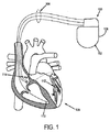
図1を参照すると、心臓再同期療法(CRT)に使用できる例示的な心臓植え込み型電気装置(CIED)100が示されている。その例示的なCIED100は、心臓内リードシステム(intracardiac lead system)104と電気的につながっている植込み型パルス発生器102を含むものである。
Referring to FIG. 1, an exemplary cardiac implantable electrical device (CIED) 100 that can be used for cardiac resynchronization therapy (CRT) is shown. The
心内リードシステム104の一部は、上大静脈のような上部静脈系の血管を通って患者の心臓106に挿入する。心内リードシステム104は、電極の位置で、空間的に分離された電極間、または電極のさまざまな組み合わせとパルス発生器102のハウジング108間で感知される心臓電気活動を示す心電図(EGM)信号を生成するか、または、その電極の位置にペーシング電気信号を伝達するように構成された一つ以上の電極を有するものである。任意ではあるが、心内リードシステム104は、心室チャンバの圧力または温度などの生理学的パラメータを感知するように構成された一つ以上の電極を含んでも良い。
A portion of the
心内リードシステム104は、患者の心臓106からの電気的信号を感知するとともに、ペーシングパルスをその心臓106に送るために、1つまたは複数の心室チャンバ内に、上に、または、その近傍に配置された1つまたは複数の心内電極110〜114を含んでも良い。図1に示したような心内電極110〜114は、左心室、右心室、左心房、及び右心房を含む1つまたは複数の心室チャンバのペースのために、上記1つまたは複数のチャンバにおける電気的活動を感知するために用いられる。リードシステム104は、心臓に電気的除細動/除細動電気ショック(cardioversion / defibrillation electrical shock) を送る1つまたは複数の除細動電極(defibrillation electrode)を含んでも良い。
The
パルス発生器102は、心臓の不整脈(arrhythmia)を検出し、リードシステム104を介して心臓106に送られる電気刺激パルスやショックの形でペーシングまたは除細動治療(defibrillation therapy)を制御する電気回路を含む。また、パルス発生器102のハウジング108は、様々な選択が可能な心内電極110〜114との組み合わせで、遠方EGMを記録するための検出電極として機能する。このようなコントローラは、プログラム及びデータ・ストレージ用メモリと電気的につながる(通信する)マイクロプロセッサで構成されている。他のコントローラの設計も、当業者によって容易に理解されるであろう。
The
コントローラは、プログラムされたモード数でCIED100を操作するように構成され、それぞれのプログラムされたモードは、感知された心臓の電気的活動に応答して、または自発的な心臓の電気的活動が無い場合に出力するものである。また、コントローラと外部通信装置、例えば、ポータブルまたはベッドサイド通信局(bed-side communication station)、患者携帯型及び/または着るタイプの通信局(patient-carried/worn communication station)、もしくは外部プログラマのような、との間の通信を容易にするために通信回路が設けられる。通信回路は、1つまたは複数の植込み型、外装型、皮膚または皮下の生理学的もしくは非生理学的センサ、患者入力装置、または情報システムとの単方向もしくは双方向通信を容易にする。
The controller is configured to operate the
コントローラは、メモリに格納されプログラムされた命令に基づいて、CIED100の動作全体を制御する。コントローラは、心内電極110〜114、及び、パルス発生器102のハウジング108とともに形成された遠視野(far-field)電極から感知された心電図電極を解釈し、プログラムされたペーシングモードに基づいて、ペーシング電気パルス(pacing electrical pulse)の供給を制御する。CIED100のセンサ回路は、特定チャネルの電極によって感知された電圧から、複数の心房、心室、及び遠視野の心電図信号を、単独または様々な組み合わせで生成する。心電図は、表面ECGに類似していて局所的、局部的、及び全心的電気活動を記録するとともに、真性またはペースビート時に起こる心臓の脱分極の経時変化及び振幅を示す。
The controller controls the entire operation of the
CIEDによって得られる電気記録図(EGM)と表面誘導システムを用いた心電計(ECG)装置によって得られる心電図との、直接的比較分析を行うための形態学的フレームワークは、2010年7月16日に出願された係属中の特許出願番号PCT/US10/42337、発明の名称「心臓再同期療法調節パラメータの自動調整のためのシステム及び方法」に記載されており、該出願の記載は本願の一部をなす。この形態学的フレームワークは、CRM装置によるペーシング前後で得られるECGで形成された心臓電気活動モデルを含んでいる。従って、このモデルは、異常な基礎全心電気活動に属する情報を伝達し、CRM装置によって生じた全心電気活動と、心室興奮波面融合(ventricular activation wavefront fusion)を最大化する所望の全心電気活動を変化させる。それによって、心臓ポンプ機能の改善確率の最大化を保障するのである。形態学的フレームワークの手法によれば、EGMは、全心活動を記録するECG装置で一般的に用いられる表面リード(誘導)システムと同じ観点を共有するわけではないが、心臓電気活動モデルは、CIEDによって記録されたEGMに直接対照する。したがって、複数のCIED EGMは、全心電気活動の表面ECG測定値に対する形態学的代替として機能する。 A morphological framework for direct comparison analysis of electrocardiograms (EGM) obtained by CIED and electrocardiographs (ECG) using surface guidance systems was issued in July 2010. Pending patent application number PCT / US10 / 42337 filed on the 16th, entitled "System and method for automatic adjustment of cardiac resynchronization therapy adjustment parameters". Part of This morphological framework includes a cardiac electrical activity model formed with ECG obtained before and after pacing with a CRM device. Therefore, this model conveys information belonging to abnormal basal global electrical activity and maximizes the electrical activity generated by the CRM device and the ventricular activation wavefront fusion. Change activities. This guarantees the maximization of the improvement probability of the heart pump function. According to the morphological framework approach, EGM does not share the same perspective as the surface lead (guidance) system commonly used in ECG devices that record total heart activity, Directly contrast to EGM recorded by CIED. Thus, multiple CIED EGMs serve as morphological alternatives to surface ECG measurements of global cardiac activity.
この形態学的フレームワークは、心室興奮パターン比較のためのQRSヒエログリフ鋳型と呼ばれている。手短に言うと、各表面電極におけるペーシング前後のQRS複合波は、R、S、Q,及びQSの4つの可能な波形要素に分解される。各QRS複合波における全要素のミリボルト("mV")で示される絶対振幅とミリ秒("ms")で示される持続時間は、特定の興奮パターンとして特徴付けて使用される。各表面電極における心室興奮は、下記表1に記載され、また図2に示す9つの可能なパターンもしくはQRSヒエログリフ(グリフ)によって特徴付けることができる。 This morphological framework is called the QRS hieroglyph template for ventricular excitation pattern comparison. In short, the QRS complex before and after pacing at each surface electrode is broken down into four possible waveform elements: R, S, Q, and QS. The absolute amplitude in millivolts ("mV") and the duration in milliseconds ("ms") of all elements in each QRS complex are characterized and used as a specific excitation pattern. Ventricular excitation at each surface electrode is described in Table 1 below and can be characterized by the nine possible patterns or QRS hieroglyphs (glyphs) shown in FIG.

左の脚ブロック(BBB)の際の典型的な心室興奮は、前平面では右から左に、水平面では前から後ろに、表面ECGでは、変動軸として記録される。QRSヒエログリフ鋳型において表面リードで記録された心臓電気活動を特徴付ける例として、この心室伝導ブロックは、表面リードI、aVL(文字:R、Rs)に優勢な陽性力、aVR(文字:QS)に陰性力、II、III、AVF(文字:R、Rs、rS、QS)に変動性の力、V1−V2(文字:QS、rS)に優勢陰性力、V3−V5(文字:rSからRとRsへ)における転移、及びV5−V6(文字:R、Rs)に優勢な陽性力を伴う典型的なヒエログリフ符号を生ずる。種々の形態の心室伝導ブロックについても、同様に、他の特徴的なグリフ符号を構築することができる。 Typical ventricular excitement during the left leg block (BBB) is recorded from right to left in the front plane, front to back in the horizontal plane, and as a variable axis in the surface ECG. As an example to characterize cardiac electrical activity recorded with surface leads in QRS hieroglyph molds, this ventricular conduction block is positive for surface leads I, aVL (letters: R, Rs), negative for aVR (letters: QS) Force, II, III, AVF (letters: R, Rs, rS, QS), variability force, V1-V2 (letters: QS, rS), dominant negative force, V3-V5 (letters: rS to R and Rs )) And a typical hieroglyph code with positive dominance in V5-V6 (letters: R, Rs). Other characteristic glyph codes can be similarly constructed for various forms of ventricular conduction blocks.
心室興奮波面融合(ventricular activation wavefront fusion)の最大の証拠(maximum evidence)を生成するために患者独自の解決策を作成する工程は連続したステップで処理される。一般に、第1ステップは、患者の基礎条件を再現する。例えば、その基礎条件は、補正された基礎伝導障害(baseline conduction disturbance)を含んでいても良い。この基礎心室活動順序シミュレーションは、逆解(inverse solution)と呼ばれている。基礎シミュレーションは、患者の基礎表面ECG解析を使用して正常心室伝導モデルシミュレーションを修正して行っても良い。これら特有の体表面ECG信号は、基礎心臓電気活動のシミュレーションを明示するものとして使用することが出来る。 The process of creating a patient-specific solution to generate maximum evidence of ventricular activation wavefront fusion is processed in successive steps. In general, the first step reproduces the patient's basic conditions. For example, the basic condition may include a corrected baseline conduction disturbance. This basic ventricular activity sequence simulation is called an inverse solution. The basic simulation may be performed by modifying the normal ventricular conduction model simulation using the patient's basic surface ECG analysis. These unique body surface ECG signals can be used to demonstrate a simulation of basic cardiac electrical activity.
下記に説明する通り、基礎モデルは、左心室興奮における遅延を起こすように繰り返し修正される。基礎シミュレーションがECG信号から生み出される限り、基礎モデルに対する修正は、基礎モデルのQRSヒエログリフ符号における変化の影響を解析することによって確認することが出来る。 As explained below, the basic model is iteratively modified to cause a delay in left ventricular excitement. As long as the basic simulation is generated from the ECG signal, modifications to the basic model can be confirmed by analyzing the effects of changes in the QRS hieroglyph code of the basic model.
従って、一般にこの工程は、興奮波面融合の最終モデルに対応する表面ECG測定値のための前方解(forward solution)を生み出す。すなわち、前方解(forward solution)によって生み出され、心室電気的非同期(ventricular electrical asynchrony)を最小化する模擬のペーシング心室活動順序(simulated paced ventricular activation sequence)と対応するECG QRSグリフパターンは、CIEDタイミング動作を命令かつ更新するために使われる。 Thus, in general, this process produces a forward solution for surface ECG measurements corresponding to the final model of excitement wavefront fusion. That is, a simulated paced ventricular activation sequence and a corresponding ECG QRS glyph pattern generated by a forward solution that minimizes ventricular electrical asynchrony is CIED timing behavior. Used to command and update
次に図3を参照すると、図には心臓再同期療法(cardiac resynchronization therapy)のためのペーシング調節パラメータを生成する方法の一工程を記載するフローチャートが示されている。ステップ302に示されるように、その方法は、患者の基礎心室活動順序の分析と特徴付けから始まる。例例えば、表面ECGリードを、心室活動順序の重要な構成要素を同定するため、基礎心室活動順序を特徴付けることに使用する。これらの重要構成要素の例は、右心室興奮時間VAT、左VAT、瘢痕容積(scar volume)、QRS持続、及び電気軸を含むものである。
Reference is now made to FIG. 3, which shows a flowchart describing one step in a method for generating pacing adjustment parameters for cardiac resynchronization therapy. As shown in
基礎心室活動順序の特徴付けの後、ステップ304に示すように、基礎モデルを生成する。この基礎モデルは、特徴付けられた基礎心室活動順序を再現し、このモデルを生成する目的は、基礎全心室伝導のために正確な患者独自のQRSヒエログリフ符号を再生する逆解(inverse solution)シミュレーションを生み出すものである。好ましくは、基礎モデルは、以下の関連条件を最小限満足するものでなければならない。第1に、基礎モデルは、枢要電極に特に注意を払い、表面ECGにおいて対応したQRSヒエログリフ符号を含むものでなければならない。第2に、基礎モデルは、表面ECGの解析によって決定され、特徴付けられた基礎心室活動順序と対応した左心室興奮時間(VAT)と右VATを含むものでなければならない。第3に、基礎モデルは、表面ECGの解析によって決定され、活動波面伝搬(activation wavefront propagation)と相互に影響しあう、局地的心筋瘢痕分布(regional myocardial scar distribution)の再生を含むものでなければならない。
After characterizing the basic ventricular activity sequence, a basic model is generated as shown in
さらに、基礎モデルは、左脚ブロック(bundle branch block; BBB)のQRSスコアに対応する左心室瘢痕容積(scar volume)の定量化を表すことが好ましい。左BBB表面測定値の心筋瘢痕(myocardial scar)の影響は、特定のQRSヒエログリフ符号に変換され、梗塞領域(infarct region)によって対立しない右方向電気力として示される。基礎心室興奮シミュレーションの左心室瘢痕の影響は、特定の解剖領域(anatomic location)により低伝搬速度領域(low propagation velocity region)と他の測定値とが結合することによって明らかとなる。特定の解剖学的瘢痕分布(anatomic distribution of scar)と全心室瘢痕容積(scar volume)のための類似情報は、心臓磁気共鳴イメージング(cardiac magnetic resonance imaging);超音波心臓検査法(echocardiography)のような超音波イメージング(ultrasound imaging);及びカテーテルによる心内膜または心外膜電気活動マッピング(catheter-based endocardial or epicardial electrical activation mapping)を含む、他の良く知られた方法によって生成することが出来る。瘢痕の容積と分布を測定する正確な技術は、心室興奮シミュレーションのための正しい解剖指示を与えている限りにおいて、特に重要なものではない。 Furthermore, the basic model preferably represents a quantification of the left ventricular scar volume corresponding to the QRS score of the left branch block (BBB). The effect of myocardial scar on the left BBB surface measurement is translated into a specific QRS hieroglyph code and is shown as a right electric force that does not conflict with the infarct region. The effect of left ventricular scar on the basic ventricular excitability simulation is revealed by the combination of a low propagation velocity region and other measurements by a specific anatomic location. Similar information for specific anatomic distribution of scar and total ventricular scar volume can be found in cardiac magnetic resonance imaging; echocardiography Other well-known methods including ultrasound imaging; and catheter-based endocardial or epicardial electrical activation mapping. The exact technique of measuring scar volume and distribution is not particularly important as long as it provides the correct anatomical instructions for ventricular excitation simulation.
基礎モデルにおいて、大きさが変わる1つまたは複数の遅延領域は、患者独自の心室伝導パターンの再現を行うために必要な場合がある。組み合わせで共通する特徴は、左側心室間隔壁(interventricular septum)の興奮波面がゆっくりと伝搬することである。遅延の開始点は、大概患者毎に様々に変化しており、ECG解析に基づくシミュレーション、または心室電気力学興奮(ventricular electromechanical activation)に関する他の生理学的情報によって様々に変化する。波面伝搬に対しその間の瘢痕または他の中断によって修正されない限り、生理学的観察結果または心室電気力学興奮(ventricular electromechanical activation)に関する他の生理学的情報源と対応し、最後に活性化したセグメントは、最も多く左心室の後部基底部に存在するものと予想される。最新活動に対する左心室の発生時間(電気活動の最初期点)は、表面ECG解析または当業者によって知られている他の測定技術によって決定される左VATにより近づくものである。 In the basic model, one or more delay regions that vary in size may be necessary to reproduce the patient's unique ventricular conduction pattern. A common feature of the combination is the slow propagation of the excitatory wavefront of the left ventricular septum. The starting point of the delay usually varies from patient to patient and varies depending on the simulation based on ECG analysis or other physiological information regarding ventricular electromechanical activation. Unless the wavefront propagation is corrected by a scar or other interruption in between, the most recently activated segment, corresponding to physiological observations or other physiological sources of ventricular electromechanical activation, is the most Many are expected to be present in the posterior base of the left ventricle. The onset time of the left ventricle for the latest activity (the initial point of electrical activity) approximates the left VAT as determined by surface ECG analysis or other measurement techniques known by those skilled in the art.
ステップ306に示されるように、基礎モデルはその後、異なる模擬のペーシング調節パラメータのセットを用いて、繰り返し修正される。この修正は、心室興奮波面融合の生成を見つける際に適用される。模擬のペーシングシミュレーション部位の解剖学的な位置は、各患者の心内膜または心外膜表面での刺激電極の公知のもしくは好ましい位置と対応している。例えば、基礎モデルに行うペーシングシミュレーションは、単一チャンバ心室タイミング(monochamber ventricular timing)の様々な操作、交差チャンバ心室タイミング(cross-chamber ventricular timing)、交差チャンバ心房心室タイミング(cross-chamber atrial-ventricular timing)、及び可変刺激強度(stimulation strength)と可変パルス持続時間(pulse duration)を含んでも良い。これらのペーシングシミュレーションのための方法はCIEDでもって実施されており、当業者に公知のものである。
As shown in
ステップ308に示す通り、修正された基礎モデルは、分析し、心室電気的非同期(ventricular electrical asynchrony)が、模擬のペーシング調節パラメータを使って最小化されるか否かを決定する。心室電気的非同期(ventricular electrical asynchrony)を最小化する方法の例としては、単一チャンバ心室ペーシング(ventricular pacing)、各チャンバ単一位置での二心室ペーシング(biventricular pacing)、及び各チャンバにおける複数位置での二心室ペーシング(biventricular pacing)がある。特定の患者に用いられるペーシング位置調整は、下記で論じるように、前方解(forward solution)モデルを再現するものである。起因する室興奮波面のリアルタイム分析は、波面融合が起こるまで解析される。波面融合活動は、当業者に公知の様々な基準に基づいて測定される。したがって、もし、心室電気的非同期(ventricular electrical asynchrony)が、決定ブロック310で決められる模擬のペーシングパラメータでもって最小化されない場合、新しいペーシング調節パラメータのセットが、ステップ312で選択され、基礎モデルはこれらの新しいペーシング調節パラメータを用いて更に修正される。心室電気的非同期(ventricular electrical asynchrony)を最小化する模擬のペーシング調節パラメータが決定されると、このパラメータのセットは、ステップ314で示されるように、CIEDまたはプログラマ用メモリに逆解(inverse solution)の条件として収納される。
As shown in
次に、格納されたペーシング調節パラメータ及び逆転条件は、ステップ316で示すように、表面ECG測定値のための前方解(forward solution)を作成することに使用する。一般に、表面ECG測定値のための前方解(forward solution)は、心室興奮波面融合の最終モデルと対応する。したがって、前方解(forward solution)によるペーシング調節パラメータは、ステップ318に示すように、CIEDまたはプログラマ用メモリに収納される。
The stored pacing adjustment parameters and reversal conditions are then used to create a forward solution for the surface ECG measurements, as shown at
マルチサイトペーシングの際の波面妨害及び逆転(wavefront opposition and reversal)は、波面融合の予想可能なECG証拠(ECG-evidence)をもたらす。この証拠は、以下の条件によって広く特徴付けられる。一つの条件は、平常または右軸偏差(right axis deviation)に対応する左軸偏差(left axis deviation)変化のような、前面電気軸(frontal plane electrical axis)に予想される変化である。前面電気軸におけるこの変化は、前面において活動の逆転を示すものである。もう一方の条件は、QRSヒエログリフ符号に変化を予測することである。例えば、右方向の力は、リードに優勢な左方向の力として現れ、これは前面で活動逆転を示す。QRSグリフ符号のこのような変化は、リードIにおけるR文字やqR、QR、またはQS文字に変化するaVLとして現れる。別の例として、前方の力は、リードに水平面での活動逆転を示す優勢な後方の力として現れる。QRSグリフ符号のそのような変化は、rS、RS、Rs、またはR文字に変化するリードV1でのQS文字として、RS、Rs、またはR文字に変化するリードV2でのQSまたはrS文字として、及びRsまたはR文字に変化するリードV3でのrSまたはRS文字として現れる。 Wavefront opposition and reversal during multi-site pacing provides predictable ECG-evidence of wavefront fusion. This evidence is broadly characterized by the following conditions: One condition is the expected change in the frontal plane electrical axis, such as a change in the left axis deviation corresponding to normal or right axis deviation. This change in the front electrical axis indicates a reversal of activity at the front. The other condition is to predict changes in the QRS hieroglyph code. For example, a rightward force appears as a leftward force that predominates on the lead, indicating an activity reversal at the front. Such a change in the QRS glyph code appears as an R character in lead I or aVL that changes to qR, QR, or QS character. As another example, the anterior force appears as a dominant posterior force that indicates reversal of activity in the horizontal plane on the reed. Such changes in the QRS glyph code are as QS characters in lead V1 changing to rS, RS, Rs, or R characters, as QS or rS characters in lead V2 changing to RS, Rs, or R characters, And appear as rS or RS characters on lead V3 that change to Rs or R characters.
心室融合の証拠を特徴付ける別に示す方法とは、ペーシング前後の活動進行波逆転を示すと予想される方向での、最大R波振幅における局在的または全体的測定値の変化を使用するものである。 Another method to characterize evidence of ventricular fusion is to use a local or global change in the maximum R-wave amplitude in a direction that is expected to show active wave reversal before and after pacing. .
局所的、地域的QRSヒエログリフ符号の予想される変化は、枢要電極で示された表面ECGリードI、aVL、V1及びV2において、最も良く表される。これらの枢要電極を使うことで、全心室興奮を、直交前面及び水平面において特徴付けることが出来る。リードIとaVLは、右から左方向(前面)における全心活動を示し、リードV1とV2は、前方から後方(水平面)への全心活動を示す。したがって、全心室興奮を解析するための別のアプローチは、精度に妥協することなく、表面ECG入力を簡易リードのセットに限定するものである。このリードのセットは、前面(I、aVL)における活動進行波逆転を評価するための1〜2のリードと水平面(V1、V2)における1〜2のリードから成立つものである。 The expected changes in the local and regional QRS hieroglyph codes are best represented on the surface ECG leads I, aVL, V1 and V2 shown on the pivot electrode. Using these pivot electrodes, total ventricular excitation can be characterized in the orthogonal front and horizontal planes. Leads I and aVL indicate total heart activity from right to left (front), and leads V1 and V2 indicate total heart activity from front to back (horizontal plane). Thus, another approach to analyzing global ventricular excitability is to limit surface ECG input to a set of simple leads without compromising accuracy. This set of leads consists of 1-2 leads for evaluating the active wave reversal at the front (I, aVL) and 1-2 leads on the horizontal plane (V1, V2).
例として、QRSヒエログリフ符号における前記の変化は、前面でのリードI及び水平面でのリードV1において最大となった。それゆえ、枢要電極I及びV1のみを含む簡易な表面ECGリードのセットでもって、二つの直交面で活動進行波逆転を検出する十分な観測能力を提供することが出来る。 As an example, the change in QRS hieroglyph code was greatest for lead I on the front and lead V1 on the horizontal plane. Therefore, a simple set of surface ECG leads including only the pivot electrodes I and V1 can provide sufficient observation capability to detect active traveling wave reversals in two orthogonal planes.
ステップ320で示されるように、前方解(forward solution)のパラメータは、上記で議論したQRSヒエログリフ形態学的フレームワーク(QRS hieroglyph morphological framework)を使うことでCIEDのペーシング調節パラメータに変換される。この患者独自のシミュレーションとモデリングの工程は、シミュレーションソフトウェアと表面ECGをCIEDプログラマにリンクさせることによって、リアルタイムで実行される。例えば、一般にCIEDプログラマは、植込み型CIEDと連続有線または無線の遠隔接続を維持できる。この工程を含むことは、心室興奮融合を示すQRSヒエログリフ符号のための代替として役立つ形態学的フレームワークを形成するものである。
As shown in
基礎心室興奮のための逆解(inverse solution)の最終パラメータは、CIED及び/またはCIEDプログラマ用のレジストリに収納される。これらのパラメータは、患者または患者独自の基底条件もしくは重要な変化に応じて、前方解(forward solution)のパラメータの将来の試行や更新に使用可能である。同様に、各前方解(forward solution)のペーシングシミュレーションと対応する臨界タイミングパラメータ(公の、単一チャンバ心室タイミング(monochamber ventricular timing);交差チャンバ心室タイミング(cross-chamber ventricular timing);交差チャンバ心房心室タイミング(cross-chamber atrial-ventricular timing);可変刺激強度(stimulation strength);可変パルス持続時間(pulse duration)等)のレジストリは、CIED及び/またはCIEDプログラマ用レジストリに自動的に収納される。このレジストリは、シミュレーションによって生成された任意の望ましい臨界タイミング調節パラメータのセットを、必ずしも逆及び前方解の工程を再実行すること無く、後日再呼び出しされ修正され実行することが出来るように、後に情報として引き出せるものとなっている。 The final parameters of the inverse solution for basic ventricular excitement are stored in a registry for CIED and / or CIED programmers. These parameters can be used for future trials and updates of forward solution parameters, depending on the patient or patient-specific basal conditions or significant changes. Similarly, pacing simulation of each forward solution and the corresponding critical timing parameters (public, single-chamber ventricular timing; cross-chamber ventricular timing; cross-chamber atrial ventricle A registry of timing (cross-chamber atrial-ventricular timing; variable stimulation strength; variable pulse duration, etc.) is automatically stored in the registry for CIED and / or CIED programmers. This registry will provide information later so that any desired set of critical timing parameters generated by the simulation can be recalled and modified at a later date without necessarily having to re-run the reverse and forward solution steps. It can be pulled out as.
ステップ322に示すように、QRSグリフ鋳型は、CIEDまたはプログラマ用メモリと連携しており、心調律管理(cardiac rhythm management)の際に、CIEDを作動するために使用される。例えば、QRSグリフ鋳型は、CIEDのペーシング調整パラメータを自動的かつ周期的に調整するために使用する。前方解(forward solution)から得られた心室興奮融合のためのQRSグリフ符号が、CIEDに基づく代替によって適切に再生することが出来ない場合、前方解(forward solution)から計算された収納ペーシング調整パラメータは、CIEDの制御作業に使われるかもしれない。この場合、臨界調節パラメーに対する周期的かつ自動的な更新は、CIEDを基本としたEGM代替(EGM surrogates)を自動的に使用するよりはむしろ、逆または前方解(forward solution)のシミュレーション工程を繰り返すことで実施することが出来る。
As shown in
このようにして、CRTのため単独またはマルチサイトペーシング前後における心室興奮波面伝搬の高精度かつ詳しい患者独自のシミュレーションを生成するシステム及び方法が、提供可能である。一般に、プレペーシング12リードECGは、基礎心室伝導妨害に関係した心室活動順序のための逆解(inverse solution)を生成するために使用される。ECGによる、模擬の心室活動順序は、ペーシングシミュレーションで操作して、活動波面融合を表示させる。さらに、波面融合シミュレーションは、12リードECGの最適ペーシングの間に、前方解(forward solution)を生成するために使用される。ペーシングECGのQRSヒエログリフ分析は、自動装置タイミング命令(automatic device timing instruction)でもって後で統合される患者独自の活動順序を同定するためのものである。 In this way, systems and methods can be provided for generating highly accurate and detailed patient-specific simulations of ventricular excitement wavefront propagation before and after single or multi-site pacing for CRT. In general, a prepaced 12-lead ECG is used to generate an inverse solution for a ventricular activity sequence related to basic ventricular conduction disturbances. Simulated ventricular activity sequence by ECG is manipulated by pacing simulation to display activity wavefront fusion. In addition, wavefront fusion simulation is used to generate a forward solution during optimal pacing of a 12-lead ECG. The pacing ECG QRS hieroglyph analysis is for identifying patient-specific activity sequences that are later integrated with automatic device timing instructions.
QRSヒエログリフ分析は、患者独自の基礎心室活動順序の特徴付けに使用される。また、基礎心室活動順序の重要要素(key component)の正確な数値的定量化が行われる。基礎心室活動順序の重要な要素の例としては、右VAT、左VAT、瘢痕容積、QRS耐性、電気軸等である。12リード表面ECGは、これらの重要要素を得て定量化するために使用されている。左心室及び右心室刺激位置の正確な知識は、解剖学上確立している。ペーシング調整パラメータの生成をガイドするために、心室電気的非同期(ventricular electrical asynchrony)の最小化として定義されているモデリング工程の数値的な定量化の終了点(endpoint)を、心室興奮波面融合として使用し表示するものである。 QRS hieroglyph analysis is used to characterize the patient's own basic ventricular activity sequence. In addition, accurate numerical quantification of key components of the basic ventricular activity sequence is performed. Examples of important elements of the basic ventricular activity sequence are right VAT, left VAT, scar volume, QRS tolerance, electrical axis, etc. A 12-lead surface ECG is used to obtain and quantify these key elements. Accurate knowledge of the left and right ventricular stimulation locations is established anatomically. Use the numerical quantification endpoint of the modeling process defined as ventricular electrical asynchrony minimization as a ventricular excitation wavefront fusion to guide the generation of pacing adjustment parameters Display.
本発明のシステムと方法は、心室電気的非同期(ventricular electrical asynchrony)を最小化する模擬の心室活動順序に対応する患者特異的かつペーシング後のECG QRSグリフパターンを同定することに使用される。QRSグリフパターンの同定は、逆左心室リモデリングの確率を最大化するために、CIEDタイミング動作を自動的に命令し、周期的な更新を行い、左心室ポンプ機能とCRTの際の複合的な臨床的改良を改善するものである。 The systems and methods of the present invention are used to identify patient-specific and post-paced ECG QRS glyph patterns that correspond to simulated ventricular activity sequences that minimize ventricular electrical asynchrony. QRS glyph pattern identification automatically commands CIED timing action and performs periodic updates to maximize the probability of reverse left ventricular remodeling, combined with left ventricular pump function and CRT. It improves clinical improvement.
以上、本発明は、1つまたは複数の好ましい実施態様の観点から説明してきたが、ここに記載したものの外にも、多くの等価物、代替物、変異形、及び改変体が可能であり、本発明の範囲内に含まれることを了解しなければならない。 Although the present invention has been described in terms of one or more preferred embodiments, many equivalents, alternatives, variants, and modifications are possible in addition to those described herein, It should be understood that it is included within the scope of the present invention.
Claims (16)
a)患者の心臓に対し心電計の表面誘導電極を用いて基礎心臓電気活動を表す信号を取得し、
b)前記ステップa)で得られた前記信号を用いて、心室伝導の基礎モデルを形成し、
c)前記ステップb)で形成した前記基礎モデルを繰り返し修正して、心室電気的非同期を最小化し、
d)前記繰り返し修正した前記基礎モデルを用いて、心室興奮波面融合を示す、更新された全心室伝導のモデルを生成し、
e)QRSヒエログリフ形態学的フレームワークを用いて、前記更新されたモデルをCRM装置のペーシング調整パラメータに変換する
ことを含む方法。 A method for performing cardiac resynchronization therapy on a heart of a patient by a cardiac rhythm management device,
a) obtaining a signal representative of basic cardiac electrical activity using a surface-inducing electrode of an electrocardiograph for the patient's heart;
b) using the signal obtained in step a) to form a basic model of ventricular conduction;
c) Iteratively modifying the basic model formed in step b) to minimize ventricular electrical asynchrony,
d) generating an updated model of global ventricular conduction showing ventricular excitatory wavefront fusion using the iteratively modified basic model;
e) using the QRS hieroglyph morphological framework to convert the updated model into CRM device pacing adjustment parameters.
心電図表面誘導から前記心臓における基礎心臓電気興奮を示す信号を受信する入力装置と、
前記心臓に電気インパルスを送って前記心臓に対し心臓再同期療法を施すインパルス供給システムと、
ペーシング調整パラメータを記憶するメモリと、
前記メモリと連携するプロセッサと、を備え、
前記プロセッサは、
前記心臓における基礎心臓電気興奮を示す前記受信信号を受信し、
前記受信信号を用いて心室伝導の基礎モデルを形成し、
前記基礎モデルを繰り返し修正して、心室電気的非同期を最小化し、
前記繰り返し修正した基礎モデルを用いて、心室興奮波面融合を示す全心室伝導の更新されたモデルを生成し、
QRSヒエログリフ形態学的フレームワークを用いて、前記更新されたモデルをペーシング調整パラメータに変換し、
前記インパルス供給システムと通信して、前記ペーシング調整パラメータに基づいて前記心臓に心臓再同期療法を施すように構成されている、心臓植え込み型電気装置。 A cardiac implantable electrical device for delivering cardiac resynchronization therapy to a patient's heart,
An input device for receiving signals indicative of basic cardiac electrical excitation in the heart from electrocardiogram surface guidance;
An impulse delivery system that delivers electrical impulses to the heart to provide cardiac resynchronization therapy to the heart;
A memory for storing pacing adjustment parameters;
A processor that cooperates with the memory,
The processor is
Receiving the received signal indicative of basic cardiac electrical excitation in the heart;
Using the received signal to form a basic model of ventricular conduction;
Repetitively modifying the basic model to minimize ventricular electrical asynchrony,
Generating an updated model of global ventricular conduction indicative of ventricular excitatory wavefront fusion using the repeatedly modified basis model;
Using the QRS hieroglyph morphological framework, convert the updated model into pacing adjustment parameters;
A cardiac implantable electrical device configured to communicate with the impulse delivery system and to apply cardiac resynchronization therapy to the heart based on the pacing adjustment parameter.
Applications Claiming Priority (3)
| Application Number | Priority Date | Filing Date | Title |
|---|---|---|---|
| US201161462366P | 2011-02-01 | 2011-02-01 | |
| US61/462,366 | 2011-02-01 | ||
| PCT/US2012/023256 WO2012106297A2 (en) | 2011-02-01 | 2012-01-31 | System and method for cardiac resychronization therapy control parameter generation using ventricular activation simulation and surface ecg registration |
Publications (2)
| Publication Number | Publication Date |
|---|---|
| JP2014505558A true JP2014505558A (en) | 2014-03-06 |
| JP2014505558A5 JP2014505558A5 (en) | 2015-03-19 |
Family
ID=46603263
Family Applications (1)
| Application Number | Title | Priority Date | Filing Date |
|---|---|---|---|
| JP2013552573A Pending JP2014505558A (en) | 2011-02-01 | 2012-01-31 | System and method for cardiac resynchronization therapy regulation parameter generation using ventricular excitation simulation and surface ECG measurements |
Country Status (5)
| Country | Link |
|---|---|
| US (1) | US8805504B2 (en) |
| EP (1) | EP2670480A4 (en) |
| JP (1) | JP2014505558A (en) |
| CN (1) | CN103415320B (en) |
| WO (1) | WO2012106297A2 (en) |
Families Citing this family (64)
| Publication number | Priority date | Publication date | Assignee | Title |
|---|---|---|---|---|
| US9510763B2 (en) | 2011-05-03 | 2016-12-06 | Medtronic, Inc. | Assessing intra-cardiac activation patterns and electrical dyssynchrony |
| US10311978B2 (en) * | 2012-01-30 | 2019-06-04 | Siemens Healthcare Gmbh | Method and system for patient specific planning of cardiac therapies on preoperative clinical data and medical images |
| US9278219B2 (en) | 2013-03-15 | 2016-03-08 | Medtronic, Inc. | Closed loop optimization of control parameters during cardiac pacing |
| US9924884B2 (en) | 2013-04-30 | 2018-03-27 | Medtronic, Inc. | Systems, methods, and interfaces for identifying effective electrodes |
| US10064567B2 (en) | 2013-04-30 | 2018-09-04 | Medtronic, Inc. | Systems, methods, and interfaces for identifying optimal electrical vectors |
| US9877789B2 (en) | 2013-06-12 | 2018-01-30 | Medtronic, Inc. | Implantable electrode location selection |
| US10251555B2 (en) | 2013-06-12 | 2019-04-09 | Medtronic, Inc. | Implantable electrode location selection |
| US9474457B2 (en) | 2013-06-12 | 2016-10-25 | Medtronic, Inc. | Metrics of electrical dyssynchrony and electrical activation patterns from surface ECG electrodes |
| US9278220B2 (en) | 2013-07-23 | 2016-03-08 | Medtronic, Inc. | Identification of healthy versus unhealthy substrate for pacing from a multipolar lead |
| US9282907B2 (en) | 2013-07-23 | 2016-03-15 | Medtronic, Inc. | Identification of healthy versus unhealthy substrate for pacing from a multipolar lead |
| US9265955B2 (en) | 2013-07-26 | 2016-02-23 | Medtronic, Inc. | Method and system for improved estimation of time of left ventricular pacing with respect to intrinsic right ventricular activation in cardiac resynchronization therapy |
| US9265954B2 (en) | 2013-07-26 | 2016-02-23 | Medtronic, Inc. | Method and system for improved estimation of time of left ventricular pacing with respect to intrinsic right ventricular activation in cardiac resynchronization therapy |
| US9986928B2 (en) | 2013-12-09 | 2018-06-05 | Medtronic, Inc. | Noninvasive cardiac therapy evaluation |
| US9320446B2 (en) | 2013-12-09 | 2016-04-26 | Medtronic, Inc. | Bioelectric sensor device and methods |
| US9233251B2 (en) * | 2014-01-16 | 2016-01-12 | Medtronic, Inc. | Bi-atrial synchronized left ventricular cardiac pacing |
| CN104856667A (en) * | 2014-02-25 | 2015-08-26 | 深圳华腾生物医疗电子有限公司 | Novel non-invasion arrhythmia diagnosis and treatment technology and multi-parameter monitor integrated product |
| US9776009B2 (en) | 2014-03-20 | 2017-10-03 | Medtronic, Inc. | Non-invasive detection of phrenic nerve stimulation |
| US9591982B2 (en) | 2014-07-31 | 2017-03-14 | Medtronic, Inc. | Systems and methods for evaluating cardiac therapy |
| US9764143B2 (en) | 2014-08-15 | 2017-09-19 | Medtronic, Inc. | Systems and methods for configuration of interventricular interval |
| US9586050B2 (en) | 2014-08-15 | 2017-03-07 | Medtronic, Inc. | Systems and methods for configuration of atrioventricular interval |
| US9586052B2 (en) | 2014-08-15 | 2017-03-07 | Medtronic, Inc. | Systems and methods for evaluating cardiac therapy |
| US11253178B2 (en) | 2015-01-29 | 2022-02-22 | Medtronic, Inc. | Noninvasive assessment of cardiac resynchronization therapy |
| US10166396B2 (en) * | 2015-04-24 | 2019-01-01 | Medtronic, Inc. | Efficient delivery of multi-site pacing |
| US9656087B2 (en) * | 2015-07-31 | 2017-05-23 | Medtronic, Inc. | Delivery of bi-ventricular pacing therapy in a cardiac medical device and medical device system |
| US11219769B2 (en) | 2016-02-26 | 2022-01-11 | Medtronic, Inc. | Noninvasive methods and systems of determining the extent of tissue capture from cardiac pacing |
| US10780279B2 (en) | 2016-02-26 | 2020-09-22 | Medtronic, Inc. | Methods and systems of optimizing right ventricular only pacing for patients with respect to an atrial event and left ventricular event |
| US10512784B2 (en) | 2016-06-27 | 2019-12-24 | Cardiac Pacemakers, Inc. | Cardiac therapy system using subcutaneously sensed P-waves for resynchronization pacing management |
| WO2018009392A1 (en) | 2016-07-07 | 2018-01-11 | Cardiac Pacemakers, Inc. | Leadless pacemaker using pressure measurements for pacing capture verification |
| CN109640809B (en) | 2016-08-24 | 2021-08-17 | 心脏起搏器股份公司 | Integrated multi-device cardiac resynchronization therapy using P-wave to pacing timing |
| CN109641129B (en) | 2016-08-24 | 2023-06-30 | 心脏起搏器股份公司 | Cardiac resynchronization with timing management using fusion facilitation |
| US10758737B2 (en) | 2016-09-21 | 2020-09-01 | Cardiac Pacemakers, Inc. | Using sensor data from an intracardially implanted medical device to influence operation of an extracardially implantable cardioverter |
| AU2017350759B2 (en) | 2016-10-27 | 2019-10-17 | Cardiac Pacemakers, Inc. | Implantable medical device with pressure sensor |
| US10463305B2 (en) | 2016-10-27 | 2019-11-05 | Cardiac Pacemakers, Inc. | Multi-device cardiac resynchronization therapy with timing enhancements |
| WO2018093605A1 (en) | 2016-11-21 | 2018-05-24 | Cardiac Pacemakers, Inc. | Leadless cardiac pacemaker providing cardiac resynchronization therapy |
| US11207532B2 (en) | 2017-01-04 | 2021-12-28 | Cardiac Pacemakers, Inc. | Dynamic sensing updates using postural input in a multiple device cardiac rhythm management system |
| US10617317B2 (en) * | 2017-02-27 | 2020-04-14 | Biosense Webster (Israel) Ltd. | Highlighting an electrode image according to an electrode signal |
| US10532213B2 (en) | 2017-03-03 | 2020-01-14 | Medtronic, Inc. | Criteria for determination of local tissue latency near pacing electrode |
| US10987517B2 (en) | 2017-03-15 | 2021-04-27 | Medtronic, Inc. | Detection of noise signals in cardiac signals |
| EP3658017B1 (en) | 2017-07-28 | 2023-07-26 | Medtronic, Inc. | Generating activation times |
| EP3658227B1 (en) | 2017-07-28 | 2021-05-12 | Medtronic, Inc. | Cardiac cycle selection |
| US11065459B2 (en) | 2017-08-18 | 2021-07-20 | Cardiac Pacemakers, Inc. | Implantable medical device with pressure sensor |
| US10433746B2 (en) | 2017-12-22 | 2019-10-08 | Regents Of The University Of Minnesota | Systems and methods for anterior and posterior electrode signal analysis |
| US10786167B2 (en) | 2017-12-22 | 2020-09-29 | Medtronic, Inc. | Ectopic beat-compensated electrical heterogeneity information |
| US11419539B2 (en) | 2017-12-22 | 2022-08-23 | Regents Of The University Of Minnesota | QRS onset and offset times and cycle selection using anterior and posterior electrode signals |
| US10492705B2 (en) | 2017-12-22 | 2019-12-03 | Regents Of The University Of Minnesota | Anterior and posterior electrode signals |
| US10799703B2 (en) | 2017-12-22 | 2020-10-13 | Medtronic, Inc. | Evaluation of his bundle pacing therapy |
| US10617318B2 (en) | 2018-02-27 | 2020-04-14 | Medtronic, Inc. | Mapping electrical activity on a model heart |
| US10668290B2 (en) | 2018-03-01 | 2020-06-02 | Medtronic, Inc. | Delivery of pacing therapy by a cardiac pacing device |
| US11482338B2 (en) | 2018-03-06 | 2022-10-25 | Biosense Webster (Israel) Ltd. | Simulation of heart pacing for modeling arrhythmia |
| US10918870B2 (en) | 2018-03-07 | 2021-02-16 | Medtronic, Inc. | Atrial lead placement for treatment of atrial dyssynchrony |
| US10780281B2 (en) | 2018-03-23 | 2020-09-22 | Medtronic, Inc. | Evaluation of ventricle from atrium pacing therapy |
| WO2019191602A1 (en) | 2018-03-29 | 2019-10-03 | Medtronic, Inc. | Left ventricular assist device adjustment and evaluation |
| US10940321B2 (en) | 2018-06-01 | 2021-03-09 | Medtronic, Inc. | Systems, methods, and interfaces for use in cardiac evaluation |
| US11304641B2 (en) | 2018-06-01 | 2022-04-19 | Medtronic, Inc. | Systems, methods, and interfaces for use in cardiac evaluation |
| US11696717B2 (en) * | 2018-11-07 | 2023-07-11 | The Cleveland Clinic Foundation | Frequency analysis for predicting left ventricular dysfunction |
| US11697025B2 (en) | 2019-03-29 | 2023-07-11 | Medtronic, Inc. | Cardiac conduction system capture |
| US11547858B2 (en) | 2019-03-29 | 2023-01-10 | Medtronic, Inc. | Systems, methods, and devices for adaptive cardiac therapy |
| CN111789590B (en) * | 2019-04-08 | 2022-04-12 | 四川锦江电子科技有限公司 | Method and system for synchronously recording stimulation in human cardiac chamber and electrophysiological recording |
| US11497431B2 (en) | 2019-10-09 | 2022-11-15 | Medtronic, Inc. | Systems and methods for configuring cardiac therapy |
| US11642533B2 (en) | 2019-11-04 | 2023-05-09 | Medtronic, Inc. | Systems and methods for evaluating cardiac therapy |
| US20210244340A1 (en) * | 2020-02-11 | 2021-08-12 | Catheter Precision, Inc. | Method of providing ventricular arrhythmia localization and myocardium wall thickness within a 3d heart model |
| US12023503B2 (en) | 2020-07-30 | 2024-07-02 | Medtronic, Inc. | ECG belt systems to interoperate with IMDs |
| US11813464B2 (en) | 2020-07-31 | 2023-11-14 | Medtronic, Inc. | Cardiac conduction system evaluation |
| CN112837595B (en) * | 2021-02-08 | 2024-05-03 | 中国人民解放军联勤保障部队第九〇〇医院 | Can adjust room chamber conduction block demonstration model of second grade |
Citations (3)
| Publication number | Priority date | Publication date | Assignee | Title |
|---|---|---|---|---|
| JP2007500550A (en) * | 2003-07-29 | 2007-01-18 | フランク, アイ. マーカス, | Optimization method for cardiac resynchronization therapy |
| JP2009524475A (en) * | 2006-01-25 | 2009-07-02 | カーディアック ペースメイカーズ, インコーポレイテッド | Optimization of cardiac resynchronization therapy parameters |
| US20090234415A1 (en) * | 2008-03-13 | 2009-09-17 | Sambelashvili Aleksandre T | Method and apparatus for determining a parameter associated with delivery of therapy in a medical device |
Family Cites Families (17)
| Publication number | Priority date | Publication date | Assignee | Title |
|---|---|---|---|---|
| CN86100247A (en) * | 1986-01-03 | 1987-07-15 | 复旦大学 | Multifunctional program-controlled heart stimulator |
| CN87200989U (en) * | 1987-01-23 | 1988-04-06 | 江苏省张家港市医疗设备厂 | Miniature extracorporeal counter pulsation |
| US6993389B2 (en) | 2001-03-30 | 2006-01-31 | Cardiac Pacemakers, Inc. | Identifying heart failure patients suitable for resynchronization therapy using QRS complex width from an intracardiac electrogram |
| US7142922B2 (en) * | 2002-12-20 | 2006-11-28 | Cardiac Pacemakers, Inc. | Method and apparatus for predicting acute response to cardiac resynchronization therapy at a given stimulation site |
| US7013176B2 (en) | 2003-01-28 | 2006-03-14 | Cardiac Pacemakers, Inc. | Method and apparatus for setting pacing parameters in cardiac resynchronization therapy |
| US6885889B2 (en) | 2003-02-28 | 2005-04-26 | Medtronic, Inc. | Method and apparatus for optimizing cardiac resynchronization therapy based on left ventricular acceleration |
| US7079895B2 (en) * | 2003-04-25 | 2006-07-18 | Medtronic, Inc. | Cardiac pacing for optimal intra-left ventricular resynchronization |
| US7558627B1 (en) | 2003-09-29 | 2009-07-07 | Pacesetter, Inc. | System and method for rapid optimization of control parameters of an implantable cardiac stimulation device |
| US7233824B2 (en) * | 2003-10-07 | 2007-06-19 | Medtronic, Inc. | Secure and efficacious therapy delivery for an extra-systolic stimulation pacing engine |
| US7308297B2 (en) * | 2003-11-05 | 2007-12-11 | Ge Medical Systems Global Technology Company, Llc | Cardiac imaging system and method for quantification of desynchrony of ventricles for biventricular pacing |
| US7570999B2 (en) | 2005-12-20 | 2009-08-04 | Cardiac Pacemakers, Inc. | Implantable device for treating epilepsy and cardiac rhythm disorders |
| US8725255B2 (en) | 2006-11-17 | 2014-05-13 | Cardiac Pacemakers, Inc. | Cardiac resynchronization therapy optimization using cardiac activation sequence information |
| EP2070562B1 (en) | 2007-12-13 | 2010-12-29 | Ela Medical | Medical device for characterising the cardiac condition of a patient fitted with an active implant for biventricular stimulation |
| US20090299423A1 (en) | 2008-06-03 | 2009-12-03 | Pacesetter, Inc. | Systems and methods for determining inter-atrial conduction delays using multi-pole left ventricular pacing/sensing leads |
| US20100152795A1 (en) * | 2008-12-11 | 2010-06-17 | Pacesetter, Inc. | Identification of dysynchrony using intracardiac electrogram data |
| US8326419B2 (en) | 2009-04-07 | 2012-12-04 | Pacesetter, Inc. | Therapy optimization via multi-dimensional mapping |
| JP2013519428A (en) * | 2010-02-12 | 2013-05-30 | ブリガム・アンド・ウイミンズ・ホスピタル・インコーポレイテッド | System and method for automatic adjustment of regulatory parameters of cardiac resynchronization therapy |
-
2012
- 2012-01-31 WO PCT/US2012/023256 patent/WO2012106297A2/en active Application Filing
- 2012-01-31 EP EP12742628.6A patent/EP2670480A4/en not_active Withdrawn
- 2012-01-31 US US13/982,155 patent/US8805504B2/en not_active Expired - Fee Related
- 2012-01-31 CN CN201280011123.4A patent/CN103415320B/en not_active Expired - Fee Related
- 2012-01-31 JP JP2013552573A patent/JP2014505558A/en active Pending
Patent Citations (3)
| Publication number | Priority date | Publication date | Assignee | Title |
|---|---|---|---|---|
| JP2007500550A (en) * | 2003-07-29 | 2007-01-18 | フランク, アイ. マーカス, | Optimization method for cardiac resynchronization therapy |
| JP2009524475A (en) * | 2006-01-25 | 2009-07-02 | カーディアック ペースメイカーズ, インコーポレイテッド | Optimization of cardiac resynchronization therapy parameters |
| US20090234415A1 (en) * | 2008-03-13 | 2009-09-17 | Sambelashvili Aleksandre T | Method and apparatus for determining a parameter associated with delivery of therapy in a medical device |
Also Published As
| Publication number | Publication date |
|---|---|
| EP2670480A4 (en) | 2015-09-02 |
| US20130310890A1 (en) | 2013-11-21 |
| CN103415320B (en) | 2016-08-10 |
| WO2012106297A2 (en) | 2012-08-09 |
| CN103415320A (en) | 2013-11-27 |
| EP2670480A2 (en) | 2013-12-11 |
| US8805504B2 (en) | 2014-08-12 |
| WO2012106297A3 (en) | 2012-11-01 |
Similar Documents
| Publication | Publication Date | Title |
|---|---|---|
| JP2014505558A (en) | System and method for cardiac resynchronization therapy regulation parameter generation using ventricular excitation simulation and surface ECG measurements | |
| JP6936346B2 (en) | Dynamic management of heart failure treatment | |
| US8175693B2 (en) | Cardiac resynchronization therapy optimization using electromechanical delay from realtime electrode motion tracking | |
| CN109982746B (en) | Leadless cardiac pacemaker providing cardiac resynchronization therapy | |
| US20180078773A1 (en) | Multi-device cardiac resynchronization therapy with mode switching timing reference | |
| CN103501856B (en) | The checking of pressure tolerance | |
| CN106132476B (en) | Cardiac resynchronization therapy optimization based on intracardiac impedance | |
| US10272248B2 (en) | Electrogram-based control of cardiac resynchronization therapy | |
| JP2014522697A5 (en) | ||
| JP2013519428A (en) | System and method for automatic adjustment of regulatory parameters of cardiac resynchronization therapy | |
| CN103796714A (en) | System and method for automated adjustment of cardiac resynchronization therapy control parameters | |
| US11207532B2 (en) | Dynamic sensing updates using postural input in a multiple device cardiac rhythm management system | |
| EP1827573B1 (en) | Device for evaluating positions of an implantable medical device | |
| CN101801457A (en) | Method, apparatus, and system to optimize cardiac preload based on measured pulmonary artery pressure | |
| US9211415B2 (en) | Phrenic nerve stimulation detection with posture sensing | |
| US10967189B2 (en) | Methods and systems for selectively delivering different types of bi-ventricular pacing | |
| US20220296906A1 (en) | Indirect sensing mechanism for cardiac monitoring | |
| CN113891739A (en) | Dynamic atrioventricular delay optimization | |
| WO2022194817A1 (en) | Indirect sensing mechanism for cardiac monitoring | |
| US20240226576A1 (en) | Heart sounds to optimize conduction system pacing | |
| US20240252827A1 (en) | Method and system for dynamic atrioventricular delay with adaptive search and rate-responsive search extension | |
| WO2024167886A1 (en) | Conduction system pacing based on heart sounds | |
| CN117042681A (en) | Indirect sensing mechanism for cardiac monitoring |
Legal Events
| Date | Code | Title | Description |
|---|---|---|---|
| RD04 | Notification of resignation of power of attorney |
Free format text: JAPANESE INTERMEDIATE CODE: A7424 Effective date: 20141021 |
|
| A521 | Request for written amendment filed |
Free format text: JAPANESE INTERMEDIATE CODE: A523 Effective date: 20150130 |
|
| A621 | Written request for application examination |
Free format text: JAPANESE INTERMEDIATE CODE: A621 Effective date: 20150130 |
|
| A977 | Report on retrieval |
Free format text: JAPANESE INTERMEDIATE CODE: A971007 Effective date: 20151225 |
|
| A131 | Notification of reasons for refusal |
Free format text: JAPANESE INTERMEDIATE CODE: A131 Effective date: 20160105 |
|
| A601 | Written request for extension of time |
Free format text: JAPANESE INTERMEDIATE CODE: A601 Effective date: 20160404 |
|
| A601 | Written request for extension of time |
Free format text: JAPANESE INTERMEDIATE CODE: A601 Effective date: 20160404 |
|
| A601 | Written request for extension of time |
Free format text: JAPANESE INTERMEDIATE CODE: A601 Effective date: 20160606 |
|
| A521 | Request for written amendment filed |
Free format text: JAPANESE INTERMEDIATE CODE: A523 Effective date: 20160628 |
|
| A02 | Decision of refusal |
Free format text: JAPANESE INTERMEDIATE CODE: A02 Effective date: 20161206 |