JP2014503256A5 - - Google Patents
Download PDFInfo
- Publication number
- JP2014503256A5 JP2014503256A5 JP2013542247A JP2013542247A JP2014503256A5 JP 2014503256 A5 JP2014503256 A5 JP 2014503256A5 JP 2013542247 A JP2013542247 A JP 2013542247A JP 2013542247 A JP2013542247 A JP 2013542247A JP 2014503256 A5 JP2014503256 A5 JP 2014503256A5
- Authority
- JP
- Japan
- Prior art keywords
- filler
- location according
- nyuso
- interpolation
- nyuso location
- Prior art date
- Legal status (The legal status is an assumption and is not a legal conclusion. Google has not performed a legal analysis and makes no representation as to the accuracy of the status listed.)
- Granted
Links
- 239000000945 filler Substances 0.000 claims description 34
- 239000000463 material Substances 0.000 claims description 11
- 238000003825 pressing Methods 0.000 claims description 11
- 238000007599 discharging Methods 0.000 claims description 4
- 230000002093 peripheral Effects 0.000 claims description 3
- 229920001817 Agar Polymers 0.000 claims description 2
- 108010010803 Gelatin Proteins 0.000 claims description 2
- 239000008272 agar Substances 0.000 claims description 2
- 239000003814 drug Substances 0.000 claims description 2
- 239000008273 gelatin Substances 0.000 claims description 2
- 229920000159 gelatin Polymers 0.000 claims description 2
- 235000019322 gelatine Nutrition 0.000 claims description 2
- 235000011852 gelatine desserts Nutrition 0.000 claims description 2
- 239000011796 hollow space material Substances 0.000 claims description 2
- 239000002904 solvent Substances 0.000 claims description 2
- 230000002708 enhancing Effects 0.000 claims 1
- 238000007789 sealing Methods 0.000 claims 1
- 210000003484 anatomy Anatomy 0.000 description 2
- 238000003780 insertion Methods 0.000 description 1
- 230000004048 modification Effects 0.000 description 1
- 238000006011 modification reaction Methods 0.000 description 1
Images


Description
さらなる構造
当業者には本開示に鑑みて本発明のさらに別の実施形態が自明になるであろうと考えられる。本発明は、決して、ここに開示され及び/又は図面に示されている特定の構造に限定されるものではなく、本発明の範囲内のあらゆる修正又は等価物をも備えたものであると理解されることができる。
以下に、出願当初の特許請求の範囲に記載された発明を付記する。
[C1]
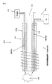
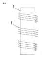
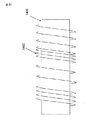
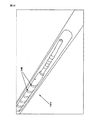
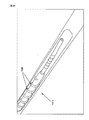
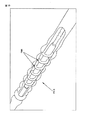
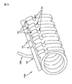
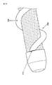
管腔内に配置される視覚化装置を受け入れられるサイズを有する管と、
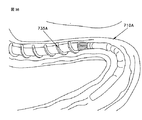
前記管の外周面に、該記管の縦軸に対して回転可能に設けられ、充填材を内部に導入可能で、該充填材に応じて機械的特性を変化する螺旋ねじと、
前記螺旋ねじ内の前記充填材に圧力を加える加圧部と、
前記螺旋ねじに設けられ、圧力を加えることによって、前記螺旋ねじから前記充填材を排出する充填材排出部と、を具備する体内挿入可能装置。
[C2]
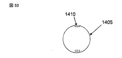
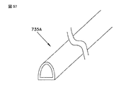
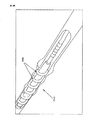
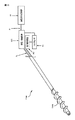
前記充填材排出部は、前記螺旋ねじに形成されたスリットと、前記スリットを閉じるシールとを含み、前記スリットを通して前記充填材が排出されるC1に記載の体内挿入可能装置。
[C3]
前記シールは、前記加圧部から圧力を加えられることで前記スリットから除去されるC2に記載の体内挿入可能装置。
[C4]
前記シールは、医学的に許容できる手段によって形成されるC2に記載の体内挿入可能装置。
[C5]
前記シールは、可溶性シールを含むC2に記載の体内挿入可能装置。
[C6]
前記スリットは、前記螺旋ねじの先端に設けられるC2に記載の体内挿入可能装置。
[C7]
前記充填材排出部は、前記加圧部から圧力を加えられることで破られる薄壁を含むC1に記載の体内挿入可能装置。
[C8]
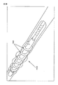
前記充填材排出部は、前記螺旋ねじに設けられたバルブを含むC1に記載の体内挿入可能装置。
[C9]
前記バルブは、ダックビルバルブであるC8に記載の体内挿入可能装置。
[C10]
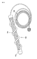
前記加圧部は小径管を含み、前記小径管を通して前記充填材を前記螺旋ねじの外へ押し出す圧力が加えられるC1に記載の体内挿入可能装置。
[C11]
前記加圧部は、前記充填材を前記螺旋ねじの外へ押し出す圧力を加えるC5に記載の体内挿入可能装置。
[C12]
前記加圧部は、前記可溶性シールを溶解させる溶媒による圧力を加えるC5に記載の体内挿入可能装置。
[C13]
前記加圧部は、手動により制御されるC1に記載の体内挿入可能装置。
[C14]
前記機械的特性は、前記加圧部から前記充填材に圧力を加えることで変化するC1に記載の体内挿入可能装置。
[C15]
前記機械的特性は、前記充填材に応じて変化するC1に記載の体内挿入可能装置。
[C16]
前記螺旋ねじは、前記充填材が導入される中空空間を有しているC1に記載の体内挿入可能装置。
[C17]
前記充填材は、治療剤を含有しているC1に記載の体内挿入可能装置。
[C18]
前記充填材は、ゼラチンを含むC1に記載の体内挿入可能装置。
[C19]
前記充填材は、寒天を含むC1に記載の体内挿入可能装置。
[C20]
前記充填材は、前記装置の視覚化を向上させるように選択されるC1に記載の体内挿入可能装置。
[C21]
管腔内に配置される視覚化装置を受け入れられるサイズを有する管と、
前記管の外周面に、該記管の縦軸に対して回転可能に設けられ、充填材を内部に導入可能で、該充填材に応じて機械的特性を変化する螺旋ねじと、
前記螺旋ねじ内の前記充填材に圧力を加える加圧部と、
前記螺旋ねじに設けられ、圧力を加えることによって、前記螺旋ねじから前記充填材を排出する充填材排出部と、を具備する体内挿入可能装置による解剖学的空間を視覚化するための方法であって、
前記螺旋ねじを回転させることによって、解剖学的構造に対して相対的に移動させる工程と、
前記管の管腔内に配置される視覚化装置を用いて、前記解剖学的空間を視覚化する工程と、を具備する方法。
[C22]
前記体内挿入可能装置の、前記解剖学的構造に対するさらなる相対移動を容易にするために、前記螺旋ねじから前記充填材を排出する工程をさらに具備するC21に記載の方法。
Further structure
It is believed that further embodiments of the invention will be apparent to those skilled in the art in view of the present disclosure. It is understood that the present invention is in no way limited to the specific structures disclosed herein and / or shown in the drawings, but includes any modification or equivalent within the scope of the present invention. Can be done.
The invention described in the scope of claims at the beginning of the application will be appended.
[C1]
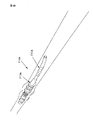
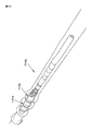
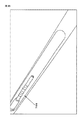
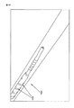
A tube having a size capable of receiving a visualization device disposed within the lumen;
A spiral screw provided on the outer peripheral surface of the tube so as to be rotatable with respect to the longitudinal axis of the recording tube, and capable of introducing a filler into the inside, and changing a mechanical property in accordance with the filler;
A pressurizing part that applies pressure to the filler in the helical screw;
A body insertable device comprising: a filler discharge portion provided on the spiral screw and discharging the filler from the spiral screw by applying pressure.
[C2]
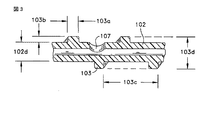
The filling material discharge unit according to C1, wherein the filling material discharge section includes a slit formed in the spiral screw and a seal that closes the slit, and the filling material is discharged through the slit.
[C3]
The intracorporeal insertable device according to C2, wherein the seal is removed from the slit when pressure is applied from the pressurizing unit.
[C4]
The insertable device according to C2, wherein the seal is formed by medically acceptable means.
[C5]
The device according to C2, wherein the seal includes a fusible seal.
[C6]
The slit can be inserted into the body according to C2, which is provided at the tip of the spiral screw.
[C7]
The injectable device according to C1, wherein the filler discharge part includes a thin wall that is broken when pressure is applied from the pressurizing part.
[C8]
The injectable device according to C1, wherein the filler discharge portion includes a valve provided on the spiral screw.
[C9]
The intra-body insertable device according to C8, wherein the valve is a duckbill valve.
[C10]
The intracorporeally insertable device according to C1, wherein the pressurizing portion includes a small diameter tube, and pressure is applied to push the filler out of the spiral screw through the small diameter tube.
[C11]
The intracorporeally insertable device according to C5, wherein the pressurizing unit applies pressure to push the filler out of the spiral screw.
[C12]
The injectable device according to C5, wherein the pressurizing unit applies pressure by a solvent that dissolves the soluble seal.
[C13]
The said pressurization part is a body insertable apparatus as described in C1 controlled manually.
[C14]
The intracorporeally insertable device according to C1, wherein the mechanical characteristics change by applying pressure to the filler from the pressurizing unit.
[C15]
The intracorporeal insertable device according to C1, wherein the mechanical properties change according to the filler.
[C16]
The internal insertion device according to C1, wherein the spiral screw has a hollow space into which the filler is introduced.
[C17]
The injectable device according to C1, wherein the filler contains a therapeutic agent.
[C18]
The device according to C1, wherein the filler includes gelatin.
[C19]
The filling material according to C1, wherein the filler includes agar.
[C20]
The body insertable device according to C1, wherein the filler is selected to improve visualization of the device.
[C21]
A tube having a size capable of receiving a visualization device disposed within the lumen;
A spiral screw provided on the outer peripheral surface of the tube so as to be rotatable with respect to the longitudinal axis of the recording tube, and capable of introducing a filler into the inside, and changing a mechanical property in accordance with the filler;
A pressurizing part that applies pressure to the filler in the helical screw;
A method for visualizing an anatomical space by a body insertable device comprising: a filler discharge portion provided on the spiral screw and discharging the filler from the spiral screw by applying pressure. And
Moving relative to the anatomy by rotating the helical screw;
Visualizing the anatomical space with a visualization device disposed within the lumen of the tube.
[C22]
The method of C21, further comprising discharging the filler from the helical screw to facilitate further relative movement of the body insertable device relative to the anatomical structure.
Claims (18)
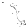
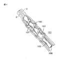
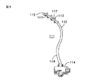
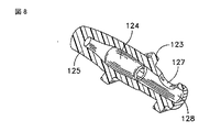
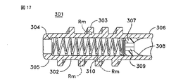
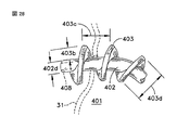
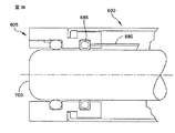
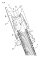
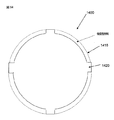
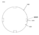
前記管ととともに回転可能となるよう前記管の外周面に設けられ、中空構造を有し、当該中空部分への充填材の供給によって機械的特性が変化可能な螺旋ねじと、
前記螺旋ねじの中空部分に充填された前記充填材に圧力を加える加圧部と、
前記螺旋ねじに設けられ、前記加圧部による圧力に応じて前記中空部分に充填された前記充填材を管腔内に排出する充填材排出部と、を具備する体内挿入装置。 The visualizing means for visualizing the lumen have a deployable inner surface, a tube rotatable relative to the visualization system,
Provided on the outer peripheral surface of the tube so as to be rotatable with said tube, having a hollow structure, and mechanical properties can be varied spiral screw by the feed of the filler into the hollow portion,
A pressurizing unit that applies pressure to the filler filled in the hollow portion of the helical screw ;
Wherein provided on the helical thread, the body inserted NyuSo location having a, a filling material discharge unit for discharging the filling material filled in the hollow portion within the lumen in response to pressure applied by the pressing.
Applications Claiming Priority (7)
| Application Number | Priority Date | Filing Date | Title |
|---|---|---|---|
| US41969410P | 2010-12-03 | 2010-12-03 | |
| US61/419,694 | 2010-12-03 | ||
| US13/100,098 | 2011-05-03 | ||
| US13/100,098 US8574220B2 (en) | 2006-02-28 | 2011-05-03 | Rotate-to-advance catheterization system |
| US13/280,228 | 2011-10-24 | ||
| US13/280,228 US8870755B2 (en) | 2007-05-18 | 2011-10-24 | Rotate-to-advance catheterization system |
| PCT/US2011/063318 WO2012078522A1 (en) | 2010-12-03 | 2011-12-05 | Rotate-to-advance catheterization system |
Publications (3)
| Publication Number | Publication Date |
|---|---|
| JP2014503256A JP2014503256A (en) | 2014-02-13 |
| JP2014503256A5 true JP2014503256A5 (en) | 2016-02-18 |
| JP5955852B2 JP5955852B2 (en) | 2016-07-20 |
Family
ID=46207467
Family Applications (1)
| Application Number | Title | Priority Date | Filing Date |
|---|---|---|---|
| JP2013542247A Expired - Fee Related JP5955852B2 (en) | 2010-12-03 | 2011-12-05 | Rotating advance catheter insertion system |
Country Status (5)
| Country | Link |
|---|---|
| EP (1) | EP2645918B1 (en) |
| JP (1) | JP5955852B2 (en) |
| CN (1) | CN103347430B (en) |
| DK (1) | DK2645918T3 (en) |
| WO (1) | WO2012078522A1 (en) |
Families Citing this family (18)
| Publication number | Priority date | Publication date | Assignee | Title |
|---|---|---|---|---|
| WO2012099974A2 (en) * | 2011-01-19 | 2012-07-26 | Fractyl Laboratories, Inc. | Devices and methods for the treatment of tissue |
| IL296643A (en) | 2012-02-27 | 2022-11-01 | Fractyl Health Inc | Heat ablation systems, devices and methods for the treatment of tissue |
| AU2013249043B2 (en) | 2012-04-19 | 2017-04-27 | Fractyl Health, Inc. | Tissue expansion devices, system and methods |
| EP3714826A1 (en) | 2012-07-30 | 2020-09-30 | Fractyl Laboratories, Inc. | Electrical energy ablation systems and devices for the treatment of tissue |
| EP2882362B1 (en) | 2012-08-09 | 2024-01-03 | Fractyl Health, Inc. | Ablation systems, devices and methods for the treatment of tissue |
| EP2903626A4 (en) | 2012-10-05 | 2016-10-19 | Fractyl Lab Inc | Methods, systems and devices for performing multiple treatments on a patient |
| EP3003461B1 (en) | 2013-06-04 | 2019-05-01 | Fractyl Laboratories, Inc. | Systems and devices for reducing the luminal surface area of the gastrointestinal tract |
| JP6603660B2 (en) | 2013-11-22 | 2019-11-06 | フラクティル ラボラトリーズ インコーポレイテッド | System, device and method for generating treatment constraints in the gastrointestinal tract |
| US10959774B2 (en) | 2014-03-24 | 2021-03-30 | Fractyl Laboratories, Inc. | Injectate delivery devices, systems and methods |
| US9844641B2 (en) | 2014-07-16 | 2017-12-19 | Fractyl Laboratories, Inc. | Systems, devices and methods for performing medical procedures in the intestine |
| EP3169260B1 (en) | 2014-07-16 | 2019-09-25 | Fractyl Laboratories, Inc. | System for treating diabetes and related diseases and disorders |
| US11185367B2 (en) | 2014-07-16 | 2021-11-30 | Fractyl Health, Inc. | Methods and systems for treating diabetes and related diseases and disorders |
| EP3445284B1 (en) * | 2016-04-21 | 2023-05-24 | Zenflow, Inc. | Systems for implants and deployment devices |
| JP6384888B2 (en) * | 2016-09-06 | 2018-09-05 | オリンパス株式会社 | Endoscope |
| AU2017371223B2 (en) | 2016-12-09 | 2023-04-27 | Zenflow, Inc. | Systems, devices, and methods for the accurate deployment of an implant in the prostatic urethra |
| NL2017970B1 (en) * | 2016-12-09 | 2018-06-29 | Stroke2Prevent B V | Improved system with an inflatable member for being arranged in the patient's respiratory tract |
| KR102238470B1 (en) * | 2018-07-03 | 2021-04-09 | 연세대학교 산학협력단 | Epidural catheter for drug eluting improved entry function |
| CN109528370B (en) * | 2019-01-17 | 2021-04-20 | 郑由周 | Intestinal tract stent auxiliary power release device |
Family Cites Families (19)
| Publication number | Priority date | Publication date | Assignee | Title |
|---|---|---|---|---|
| US5084061A (en) * | 1987-09-25 | 1992-01-28 | Gau Fred C | Intragastric balloon with improved valve locating means |
| US5049130A (en) * | 1988-12-23 | 1991-09-17 | Cardiovascular Imaging Systems, Inc. | System and method for pressure filling of catheters |
| US4973319A (en) | 1989-05-10 | 1990-11-27 | Therex Corp. | Slit valve medical catheter |
| JP3310068B2 (en) * | 1993-09-20 | 2002-07-29 | テルモ株式会社 | Endoscope insertion guide |
| US5474542A (en) * | 1993-10-01 | 1995-12-12 | Gandi; Robert A. | Catheter having imperforate protective barrier and method for making and using the same |
| JP2002507922A (en) * | 1997-07-03 | 2002-03-12 | プライアント エンドスコピック インストルメンツ リミテッド | Flexible sheath for guiding a medical device into a tube |
| US6749617B1 (en) * | 1997-11-04 | 2004-06-15 | Scimed Life Systems, Inc. | Catheter and implants for the delivery of therapeutic agents to tissues |
| US6152943A (en) * | 1998-08-14 | 2000-11-28 | Incept Llc | Methods and apparatus for intraluminal deposition of hydrogels |
| US6375637B1 (en) * | 1999-08-27 | 2002-04-23 | Gore Enterprise Holdings, Inc. | Catheter balloon having a controlled failure mechanism |
| US6679860B2 (en) * | 2001-06-19 | 2004-01-20 | Medtronic Ave, Inc. | Intraluminal therapy catheter with inflatable helical member and methods of use |
| JP4418265B2 (en) * | 2004-03-15 | 2010-02-17 | オリンパス株式会社 | Endoscopy device for endoscope |
| US20060161102A1 (en) * | 2005-01-18 | 2006-07-20 | Newcomb Kenneth R | Controlled failure balloon catheter assemblies |
| JP2006305320A (en) * | 2005-03-28 | 2006-11-09 | Olympus Corp | Medical instrument insertion device and medical instrument insertion device system |
| DK2160129T3 (en) * | 2007-05-18 | 2020-11-30 | Spirus Medical Inc | Catheterization system with advancement by rotation |
| US7841994B2 (en) * | 2007-11-02 | 2010-11-30 | Boston Scientific Scimed, Inc. | Medical device for crossing an occlusion in a vessel |
| EP2278908B1 (en) * | 2008-04-27 | 2021-06-02 | Loma Vista Medical, Inc. | Biological navigation device |
| JP2009273609A (en) * | 2008-05-14 | 2009-11-26 | Nippon Sherwood Medical Industries Ltd | Catheter with valve |
| EP2291108A4 (en) * | 2008-05-17 | 2013-01-23 | Spirus Medical Inc | Rotate-to-advance catheterization system |
| WO2012054934A1 (en) * | 2010-10-22 | 2012-04-26 | Olympus Endo Technology America Inc. | Rotate-to-advance catheterization system |
-
2011
- 2011-12-05 EP EP11846524.4A patent/EP2645918B1/en not_active Not-in-force
- 2011-12-05 DK DK11846524.4T patent/DK2645918T3/en active
- 2011-12-05 JP JP2013542247A patent/JP5955852B2/en not_active Expired - Fee Related
- 2011-12-05 WO PCT/US2011/063318 patent/WO2012078522A1/en active Application Filing
- 2011-12-05 CN CN201180058202.6A patent/CN103347430B/en not_active Expired - Fee Related
Similar Documents
| Publication | Publication Date | Title |
|---|---|---|
| JP2014503256A5 (en) | ||
| CN103764051B (en) | A kind of paracentesis pericardii needle assemblies | |
| JP5694917B2 (en) | Catheter cleaning mandrel | |
| RU2018145543A (en) | DEVICE AND DELIVERY SYSTEM FOR TREATING ANEURISM | |
| RU2016116802A (en) | SPRING CYLINDER | |
| JP2019510579A5 (en) | Delivery system having an introducer sheath and a distal sheath | |
| JP2019511345A5 (en) | ||
| JP2011518606A5 (en) | ||
| CN105578974B (en) | Stone basket type holds pliers | |
| JP2013543410A5 (en) | ||
| JP2008539989A5 (en) | ||
| CN105873527B (en) | Stone basket type holds pliers | |
| JP2012502759A5 (en) | ||
| EP3345553A3 (en) | Occlusive device | |
| RU2014152907A (en) | CATHETER WITH EXECUTION WITH THE POSSIBILITY OF BENDING THE SLEEVE AND METHOD OF USE OF THE CATHETER SYSTEM | |
| RU2015126290A (en) | STENT INSTALLATION TOOL | |
| RU2015136529A (en) | METHODS AND DEVICE FOR DIAGNOSTIC OF THE PHALLOPY PIPES | |
| CN104353177B (en) | Medical operation sheath | |
| JP2009528890A (en) | Rotating dilator with internal thread | |
| US11957860B2 (en) | Fiducial deployment mechanisms, and related methods of use | |
| CN104368080B (en) | Medical operation sheath | |
| JP2019514492A5 (en) | ||
| CN110292704A (en) | Canal of uterine cervix extension fixture | |
| EP2437681B1 (en) | Probe for artificial insemination, in particular for pigs | |
| CN203059795U (en) | Operational sleeve pipe capable of enlarging endoscope |