JP2014234873A - Vibration reduction device - Google Patents
Vibration reduction device Download PDFInfo
- Publication number
- JP2014234873A JP2014234873A JP2013116898A JP2013116898A JP2014234873A JP 2014234873 A JP2014234873 A JP 2014234873A JP 2013116898 A JP2013116898 A JP 2013116898A JP 2013116898 A JP2013116898 A JP 2013116898A JP 2014234873 A JP2014234873 A JP 2014234873A
- Authority
- JP
- Japan
- Prior art keywords
- inner cylinder
- axis
- additional spring
- vibration
- inertia mass
- Prior art date
- Legal status (The legal status is an assumption and is not a legal conclusion. Google has not performed a legal analysis and makes no representation as to the accuracy of the status listed.)
- Granted
Links
Images


Abstract
Description
本発明は、相対振動する二部材間に介装されて、その相対振動を低減させるための振動低減装置、特に回転錘による慣性力を反力として利用する(回転慣性質量機構に属する)振動低減装置に関する。 The present invention is a vibration reduction device that is interposed between two members that vibrate relative to each other and reduces the relative vibration, and particularly uses the inertial force generated by the rotating weight as a reaction force (belonging to a rotary inertial mass mechanism). Relates to the device.
近年、慣性質量ダンパーを建物の層間に設置し、慣性質量を付加することによって、地震時の建物の応答変位を効果的に低減することが行なわれている。すなわち、慣性質量ダンパーは、その両端の相対加速度に比例した反力を生じる装置であり、ボールねじ機構を利用して回転錘の実際の質量の数千倍もの慣性質量効果を得ることができるため、制振建物で既に実用化されている。 In recent years, an inertial mass damper is installed between layers of a building, and an inertial mass is added to effectively reduce the response displacement of the building during an earthquake. That is, an inertial mass damper is a device that generates a reaction force proportional to the relative acceleration at both ends, and an inertial mass effect that is several thousand times the actual mass of a rotating weight can be obtained using a ball screw mechanism. It has already been put into practical use in damping buildings.
また、免震建物に対しても慣性質量ダンパーを適用して免震層の応答変位を低減する効果が確認され、これにより、実用化の検討が進められている。この一方で、免震建物に適用する場合、慣性質量ダンパーを単に免震層に付加しただけでは、慣性質量ダンパーの設置によって地震動の高振動数成分が建物に作用して建物の応答加速度の増大を招くという問題がある。 In addition, the effect of reducing the response displacement of the seismic isolation layer by applying inertial mass dampers to the seismic isolation building has been confirmed, and the practical application is being studied. On the other hand, when applied to a base-isolated building, if an inertial mass damper is simply added to the base isolation layer, the high-frequency component of the ground motion acts on the building due to the installation of the inertial mass damper, increasing the response acceleration of the building There is a problem of inviting.
これに対し、本願の出願人は、慣性質量ダンパーである回転慣性質量機構に対し、複数の皿ばねなどを用いて圧縮力、引張力の双方に対応可能に構成した付加ばね機構を直列に接続配置した振動低減装置(慣性質量ダンパー)の発明を既に特許出願している(例えば、特許文献1参照)。この振動低減装置では、慣性質量ダンパーによる慣性質量効果で免震層の応答変位を効果的に低減しつつ、慣性質量ダンパーに直列に接続した付加ばねで建物への高振動数成分を吸収させ、この付加ばねによる振動吸収効果によって建物の応答加速度が増大することを防止できるようにしている。 In contrast, the applicant of the present application connected in series an additional spring mechanism that is configured to be able to handle both compressive force and tensile force using a plurality of disc springs, etc., to a rotary inertial mass mechanism that is an inertial mass damper. A patent application has already been filed for the invention of the arranged vibration reducing device (inertial mass damper) (for example, see Patent Document 1). In this vibration reduction device, while effectively reducing the response displacement of the seismic isolation layer by the inertia mass effect by the inertia mass damper, the high frequency component to the building is absorbed by the additional spring connected in series to the inertia mass damper, The response acceleration of the building can be prevented from increasing due to the vibration absorption effect of the additional spring.
しかしながら、上記の回転慣性質量機構と付加ばね機構を直列に接続してなる振動低減装置においては、付加ばねとして皿バネを用いることで長さを短くしコンパクト化を図ることができるものの、それでも、例えば皿バネ群を備えた付加ばね機構を回転慣性質量機構に直列に接続することでその全長がかなり大きくなって、場合によっては免震層のスパン(柱内のり間隔)よりも大きな長さになってしまう。 However, in the vibration reduction device formed by connecting the rotary inertia mass mechanism and the additional spring mechanism in series, the length can be shortened by using a disc spring as the additional spring, but still, For example, by connecting an additional spring mechanism with a disc spring group in series to a rotary inertia mass mechanism, the overall length becomes considerably large, and in some cases, the length is longer than the span of the seismic isolation layer (column spacing). End up.
さらに、このように大きな長さを有する振動低減装置を、免震層を挟んで上下の建物構造体にピン接合して設置することになるため、自重によって振動低減装置に撓みが生じたり、圧縮時に座屈変形して直線性を維持できなくなり、その結果、所望の振動低減性能を発揮できなくなることも考えられる。 Furthermore, since the vibration reduction device having such a large length is installed by pin joining to the upper and lower building structures with the seismic isolation layer in between, the vibration reduction device is bent or compressed by its own weight. It is conceivable that the linearity cannot be maintained due to buckling deformation sometimes, and as a result, the desired vibration reduction performance cannot be exhibited.
上記事情に鑑み、本発明は、回転慣性質量機構に対して付加ばね機構を組み合わせ、高振動数成分の吸収を可能にしつつ、装置のコンパクト化、軽量化を可能にした振動低減装置を提供することを目的とする。 In view of the above circumstances, the present invention provides a vibration reduction device that combines a rotary inertia mass mechanism with an additional spring mechanism to enable absorption of a high frequency component, and to make the device compact and lightweight. For the purpose.
上記の目的を達するために、この発明は以下の手段を提供している。 In order to achieve the above object, the present invention provides the following means.
本発明の振動低減装置は、相対振動する二部材の間の相対振動を低減させるための振動低減装置であって、回転慣性質量機構と付加ばね機構を直列に接続して構成され、前記回転慣性質量機構は、ボールねじと、ボールねじに螺着し、軸線方向に前記ボールねじが進退するとともに前記軸線周りに回転可能に、且つ前記軸線周りに移動不能に設けられたボールナットと、前記ボールナットに取り付けられ、前記ボールナットに従動して前記軸線周りに回転可能に設けられた回転錘とを備え、前記付加ばね機構は、外筒と、外筒の内部に、互いの軸線を同軸上に配し、且つ前記軸線方向に相対的に進退可能に設けられた内筒と、外筒の内面と内筒の外面の間に設けられ、外筒と内筒が相対変位した際に外筒と内筒の相対位置を初期状態に戻すように外筒及び/又は内筒を前記軸線方向に付勢するばね部材とを備え、前記内筒の一端を前記回転慣性質量機構に固着し、前記ボールねじを前記内筒に挿通して構成されていることを特徴とする。 The vibration reducing device of the present invention is a vibration reducing device for reducing relative vibration between two members that vibrate relatively, and is configured by connecting a rotary inertia mass mechanism and an additional spring mechanism in series. The mass mechanism includes a ball screw, a ball nut that is screwed to the ball screw, the ball screw is advanced and retracted in the axial direction, is rotatable about the axis, and is immovable about the axis, and the ball A rotary weight attached to the nut and driven to rotate around the axis following the ball nut, and the additional spring mechanism is coaxially arranged between the outer cylinder and the outer cylinder. And an inner cylinder provided between the inner cylinder and the outer surface of the inner cylinder so that the outer cylinder and the inner cylinder are relatively displaced. And return the relative position of the inner cylinder to the initial state. And a spring member for urging the outer cylinder and / or the inner cylinder in the axial direction, one end of the inner cylinder being fixed to the rotary inertia mass mechanism, and the ball screw being inserted into the inner cylinder. It is characterized by.
また、本発明の振動低減装置においては、前記装置本体部の中間部分を支持する中間支承機構を備え、前記中間支承機構が、前記回転慣性質量機構と前記付加ばね機構を直列に接続してなる装置本体部に一端を接続し、前記軸線に直交する方向に延設された支持部材と、前記支持部材の他端及び/又は前記支持部材の他端が当接する当接面に設けられた摩擦低減手段とを備えていることが望ましい。 The vibration reducing device of the present invention further includes an intermediate support mechanism that supports an intermediate portion of the apparatus main body, and the intermediate support mechanism is formed by connecting the rotary inertia mass mechanism and the additional spring mechanism in series. Friction provided on one end of the apparatus main body, a support member extending in a direction perpendicular to the axis, and a contact surface on which the other end of the support member and / or the other end of the support member abuts It is desirable to provide a reduction means.
本発明の振動低減装置においては、地震が発生し、二部材に相対振動が発生した際に、これに応じて回転慣性質量機構のボールねじが軸線方向に進退し、ボールナットが回転するとともに回転錘が回転し、回転錘の実際の質量の数千倍もの慣性質量効果を得ることができる。これにより、例えば、積層ゴムなどの免震装置が設置された免震建物の免震層内にこの振動低減装置を取り付けることで、免震層の応答変位を大幅に低減することが可能になる。 In the vibration reducing device of the present invention, when an earthquake occurs and relative vibration occurs between the two members, the ball screw of the rotary inertial mass mechanism advances and retreats in the axial direction accordingly, and the ball nut rotates and rotates. The weight rotates, and an inertial mass effect several thousand times as large as the actual mass of the rotating weight can be obtained. This makes it possible to significantly reduce the response displacement of the seismic isolation layer, for example, by installing this vibration reducing device in the seismic isolation layer of the seismic isolation building where a seismic isolation device such as laminated rubber is installed. .
また、回転慣性質量機構によって慣性質量効果が発揮されるとともに、付加ばね機構のばね部材が縮むことで圧縮力と引張力の双方で直列ばねとして機能することができる。これにより、この付加ばね機構によって、高振動数域において回転慣性質量機構に過大な相対加速度が作用することを防止できるため、免震建物に適用した場合であっても、建物の応答加速度が増大することを確実に防止できる。 In addition, the inertial mass effect is exhibited by the rotary inertial mass mechanism, and the spring member of the additional spring mechanism is contracted so that both the compression force and the tensile force can function as a series spring. As a result, this additional spring mechanism can prevent excessive relative acceleration from acting on the rotating inertial mass mechanism in the high frequency range, so that the response acceleration of the building increases even when applied to a base-isolated building. Can be surely prevented.
そして、本発明の振動低減装置においては、回転慣性質量機構と付加ばね機構を直列に接続して構成した場合であっても、付加ばね機構の内筒の一端を回転慣性質量機構に接続し、ボールねじを内筒の内部に挿通して構成されているため、すなわち、付加ばね機構と回転慣性質量機構のボールねじとが軸線方向に重なるため、単純に両機構を直列した従来の振動低減装置と比較し、振動低減装置の長さを短くし、コンパクト化することが可能になる。 And, in the vibration reducing device of the present invention, even when the rotary inertia mass mechanism and the additional spring mechanism are connected in series, one end of the inner cylinder of the additional spring mechanism is connected to the rotary inertia mass mechanism, Since the ball screw is inserted into the inner cylinder, that is, since the additional spring mechanism and the ball screw of the rotary inertia mass mechanism overlap in the axial direction, the conventional vibration reduction device in which both mechanisms are simply connected in series. Compared to the above, the length of the vibration reducing device can be shortened and made compact.
また、本発明の振動低減装置においては、直列に接続配置された回転慣性質量機構と付加ばね機構からなる装置本体部の中間部分を中間支承機構によって支持するように構成することで、全長がある程度長くなっても、自重によって振動低減装置(装置本体部)に撓みが生じることがない。 Further, in the vibration reducing device of the present invention, the intermediate portion of the device main body composed of the rotary inertia mass mechanism and the additional spring mechanism connected in series is supported by the intermediate support mechanism, so that the overall length is somewhat. Even if the length becomes longer, the vibration reducing device (device main body) is not bent due to its own weight.
さらに、地震が発生し、二部材に相対振動が発生し、回転慣性質量機構や付加ばね機構がそれぞれ稼働した際に、これら回転慣性質量機構や付加ばね機構の挙動に合わせ、摩擦低減手段によって中間支承機構が動くため、地震によって振動低減装置に圧縮力が作用した場合であっても装置本体部が座屈することがない。すなわち、装置本体部の直線性を確実に維持することができ、これに伴い、所望の振動低減性能を確実に発揮させることが可能になる。 Furthermore, when an earthquake occurs, relative vibration occurs between the two members, and the rotary inertia mass mechanism and the additional spring mechanism operate, the friction reduction means adjusts the intermediate to the behavior of the rotary inertia mass mechanism and the additional spring mechanism. Since the support mechanism moves, the apparatus main body does not buckle even when a compressive force is applied to the vibration reducing apparatus due to an earthquake. That is, the linearity of the apparatus main body can be reliably maintained, and accordingly, desired vibration reduction performance can be reliably exhibited.
さらに、中間支承機構によって回転慣性質量機構と付加ばね機構を支持するように構成することでボールねじの直線性も維持できるので、回転慣性質量機構のボールねじの軸径を小さくしても所定の振動低減性能を得ることが可能になる。これにより、所望の振動低減性能を確保しつつ、ボールねじ、内筒等の構成部材を縮小化し、振動低減装置のさらなる軽量化を図ることが可能になる。 In addition, since the linearity of the ball screw can be maintained by supporting the rotary inertia mass mechanism and the additional spring mechanism by the intermediate support mechanism, a predetermined amount can be obtained even if the ball diameter of the rotary inertia mass mechanism is reduced. Vibration reduction performance can be obtained. Thereby, it is possible to reduce the weight of the vibration reducing device by reducing the components such as the ball screw and the inner cylinder while securing the desired vibration reducing performance.
以下、図1から図6を参照し、本発明の一実施形態に係る振動低減装置について説明する。 Hereinafter, a vibration reducing device according to an embodiment of the present invention will be described with reference to FIGS.
本実施形態の振動低減装置は、例えば、免震建物の免震層を挟んで上下の上部構造と下部構造にそれぞれ両端部側をピン接合して免震層内に設置され、地震などによって相対振動する二部材の相対振動を低減させるために用いられる。
なお、本発明に係る振動低減装置は、例えば建物の柱と梁で囲まれた架構面内などに設置して、地震などによって相対振動する二部材の相対振動を低減させる制振建物(制振システム)の構成要素として用いるようにしてもよい。
The vibration reduction device of the present embodiment is installed in the base isolation layer by pin-bonding both end sides to the upper and lower upper and lower structures with the base isolation layer of the base isolation building interposed therebetween, for example. Used to reduce the relative vibration of two vibrating members.
Note that the vibration reducing device according to the present invention is installed in, for example, a frame surface surrounded by pillars and beams of a building to reduce the relative vibration of two members that vibrate relative to each other due to an earthquake or the like. It may be used as a component of the system.
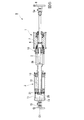
そして、本実施形態の振動低減装置Aは、図1、及び図2から図5に示すように、回転慣性質量機構1と付加ばね機構2と中間支承機構3とを備え、回転慣性質量機構1と付加ばね機構2を直列に接続して構成されている。また、本実施形態では、直列に接続した回転慣性質量機構1と付加ばね機構2からなる装置本体部4(振動低減装置A)がその軸線O1方向を水平方向に配して設置される。
As shown in FIGS. 1 and 2 to 5, the vibration reducing apparatus A according to the present embodiment includes a rotary
回転慣性質量機構1は、中心軸線O1を装置本体部4の軸線O1と同軸上に配して設けられたボールねじ5と、ボールねじ5に螺着して配設されたボールナット6と、ボールナット6に取り付けられ、ボールナット6の回転に従動して回転する回転錘7とを備えて構成されている。
The rotary
ボールねじ5は、その一端5aに建物の構成体等に接続するためのボールジョイントやクレビスなどの連結部材8が取り付けられている。また、ボールねじ5の他端5bには、ボールねじよりも大径で円板状のガイド板9がボールねじ5の軸線O1と互いの中心軸線を同軸上に配した状態で取り付けられている。
The
また、ボールねじ5に螺着したボールナット6は、軸受け10に支持されている。軸受け10は、詳細を後述する付加ばね機構2の内筒12の一端12aが接続されて、軸線O1周りに回転不能に且つ軸線O1方向に移動不能に固設される円環状の外輪10aと、外輪10aの内孔内に配されて軸線O1周りに回転可能に支持された円環状の内輪10bとを備えて形成されている。そして、ボールねじ5が軸受け10の内輪10bの中心孔に挿通して配設されるとともに、ボールナット6が軸受け10の内輪10bに固設されている。これにより、ボールナット6は、軸線O1周りに回転可能に、且つ軸線O1方向に移動不能に配設されている。
A
さらに、ボールナット6に回転錘7が一体に固設されている。回転錘7は例えば略円筒状に形成され、ボールねじ5を内部に挿通し、ボールねじ5と互いの軸線O1を同軸上に配した状態でボールナット6に固着して配設されている。
Further, a rotary weight 7 is integrally fixed to the
次に、付加ばね機構2は、円筒状に形成された外筒11と、外筒11よりも外径が小の円筒状に形成され、外筒11の内部に互いの軸線O1を同軸上に配して設けられた内筒12と、外筒11と内筒12の間に配設された付加ばね(ばね部材)13とを備えて構成されている。
Next, the
外筒11は、所定長さの高軸剛性かつ高曲げ剛性の中空円筒体であって、その他端11b(図中左側の端部)に内部を閉塞させるように円板状の接続板14が固着され、この接続板14に、振動低減装置Aの他端を建物の構成体等の接続するためのボールジョイントやクレビスなどの連結部材15が取り付けられている。また、外筒11の一端11a側(図中右側の端部)には、内筒12を挿通させる挿通孔を中心に貫通形成した円環状の支持板16が内部を閉塞させるように固着されている。
The
また、外筒11には、一端11a側に、支持板16に固着して設けられ、外筒11を内筒12に対して軸線O1方向に案内して相対的に進退させるためのリニアガイド17が設けられている。さらに、外筒11には、他端11b側に、内面から径方向内側に突出し、他端11bから軸線O1方向一端11a側に向けて延びる凸部18が設けられている。また、この凸部18は、振動低減装置Aのストローク量に応じた軸線O1方向の長さ寸法で形成されている。
In addition, the
内筒12は、所定長さの高軸剛性かつ高曲げ剛性の中空円筒体であって、支持板16の挿通孔に他端12b側から挿通して外筒11内に配設され、一端12a側を外筒11から外側に配して設けられている。また、このとき、内筒12は、その一端12aを、ボールねじ5を回転可能に軸支する軸受け10の外輪10aに固着し、内輪10bの内孔と互いの軸線O1が同軸上に配されるようにして設けられている。さらに、内筒12は、他端12bと外筒11の他端11bに固着された接続板14との軸線O1方向の間に所定の間隔(振動低減装置Aのストローク量を規定する間隔)を設けて外筒11内に配設されている。
The
また、内筒12には、図1、図3から図5に示すように、外筒11の支持板16から外側に延設された一端12aに、径方向外側に突出し、軸線O1方向に延び、リニアガイド17が係合して外筒11を内筒12に対して軸線O1方向に案内し相対回転せずに進退させるためのリニアガイドレール19が設けられている。さらに、内筒12には、その他端12bに、内筒12の外径よりも大きく、外筒11の内径よりも小さい直径を有する円板状の係止板20が固着されている。
Further, as shown in FIGS. 1 and 3 to 5, the
また、内筒12の他端12b側には、内筒12の外径と略等しい内径を備え、外筒11の内径よりも僅かに小さい外径を備えて略円環状に形成されたストローク規定板21が、その中心孔に内筒12の他端12b側を挿通して取り付けられている。このストローク規定板21は、図1及び図2に示すように、外筒11の内面に当接する外周ローラー21aと、内筒12の外面に当接する内周ローラー21bを備えている。そして、ストローク規定板21は、これらローラー21a、21bによって外筒11と内筒12のそれぞれに対し、相対的に軸線O1方向に進退自在に設けられている。また、このとき、ストローク規定板21は、外筒11の凸部18の軸線O1方向一端に当接することで、外筒11に対し、さらなる軸線O1方向他端11b側への移動が規制され、内筒12の係止板20に当接することで、内筒12に対し、さらなる軸線O1方向他端12b側への相対移動が規制されている。
The
次に、付加ばね機構2のばね部材(付加ばね)13は、内筒12の外面と外筒11の内面の間、且つストローク規定板21と支持板16の軸線O1方向の間に設けられている。本実施形態において、ばね部材13は、複数枚の皿バネが直列に重ねられた1組の皿バネ群を複数組軸線O1方向に並設して構成されている。なお、図1では軸線O1方向中間部分のばね部材13を省略して図示している。
Next, the spring member (addition spring) 13 of the
これにより、ばね部材13による付勢力でストローク規定板21に軸線O1方向他端側に押圧する力が作用し、通常時には、この付勢力を受けたストローク規定板21が凸部18に当接してそれ以上軸線O1方向他端側に移動しないように設けられている。また、この状態で、ストローク規定板21に内筒12に設けられた係止板20が当接される。
As a result, a force that presses the
そして、内筒12に対して外筒11が軸線O1方向一端側に相対変位する際には、すなわち、振動低減装置Aに圧縮側の力が作用した際には、凸部18にストローク規定板21が押圧され、これとともに内筒12に対してストローク規定板21が軸線O1方向一端12a側に相対変位し、ばね部材13が縮む。また、内筒12に対して外筒11が軸線O1方向他端側に相対変位する際には、すなわち、振動低減装置Aに引張側の力が作用した際には、係止板20にストローク規定板21が押圧され、これとともに外筒11に対してストローク規定板21が軸線O1方向一端11a側に相対変位し、ばね部材13が縮む。
これにより、本実施形態の付加ばね機構2は、ばね部材13が縮むことで外力を吸収するとともに圧縮力と引張力の双方の外力に対応できるように構成されている。
When the
Thereby, the
なお、ストローク規定板21や支持板16のばね部材13と当接する面や、外筒11の内面、内筒12の外面に硬質ゴム等の緩衝材が取り付け、付加ばね機構2の作動時に騒音(機械音)が発生したり、摩耗が生じることを防止するように構成してもよい。
A cushioning material such as hard rubber is attached to the surface of the
そして、本実施形態の振動低減装置Aは、上記のように構成した回転慣性質量機構1と付加ばね機構2とが、回転慣性質量機構1のボールねじ5の他端5b側を内筒12の一端12a側からその内部に挿入配置するとともに、この内筒12の一端12aを軸受け10の外輪10aに着脱可能に固着することによって、互いに直列配置した状態で一体に接続されている。また、この振動低減装置Aは、例えば、慣性質量2500ton、負担力500kN、ストローク±600mm、直列バネ4kN/mmの装置として構成されている。
In the vibration reducing device A of the present embodiment, the rotary
一方、本実施形態の振動低減装置Aにおいては、軸線O1方向を水平方向に向けて直列に接続配置された回転慣性質量機構1と付加ばね機構2からなる装置本体部4を支持する中間支承機構3を備えている。
On the other hand, in the vibration reducing apparatus A of the present embodiment, an intermediate support mechanism that supports the apparatus
中間支承機構3は、装置本体部4(振動低減装置A)の中間部分、本実施形態では軸受け10の外輪10aに一端を接続し、軸線O1に直交する方向(鉛直方向)の下方に向けて延設された支持部材3aと、支持部材3aの他端及び/又は支持部材3aの他端が当接する当接面22に設けられた摩擦低減手段3bとを備えて構成されている。また、摩擦低減手段3bとしては、例えばローラー、ベアリング、テフロン(登録商標)シートなどの滑り材などを適用することができる。
The intermediate support mechanism 3 has one end connected to an intermediate portion of the apparatus main body 4 (vibration reducing apparatus A), in this embodiment, the
上記構成からなる本実施形態の振動低減装置Aにおいては、例えば、建物の上部構造に他端側の連結部材15を連結し、下部構造に一端側の連結部材8を連結し、軸線O1方向を水平方向に向けた状態で免震層内に設置される。また、このとき、中間支承機構3の下端(他端)が下部構造の当接面22に当接し、直列に接続配置された回転慣性質量機構1と付加ばね機構2とが中間支承機構3によって支持される。
In the vibration reducing apparatus A of the present embodiment having the above-described configuration, for example, the connecting
そして、地震が発生し、免震層を挟んで上下の上部構造と下部構造(二部材)に相対振動(相対変位)が発生した際には、これに応じて回転慣性質量機構1のボールねじ5が軸線O1方向に進退し、軸受け10の内輪10bに支持されたボールナット6が回転するとともに回転錘7が回転する。これにより、回転錘7の実際の質量の数千倍もの慣性質量効果が得られ、積層ゴムなどの免震装置を設置した免震層の応答変位が大幅に低減することになる。
When an earthquake occurs and relative vibration (relative displacement) occurs in the upper and lower upper structures and lower structures (two members) with the seismic isolation layer sandwiched therebetween, the ball screw of the rotary
また、上部構造と下部構造に相対振動が発生し、回転慣性質量機構1によって慣性質量効果が発揮されるとともに、付加ばね機構2にも相対振動が作用する。そして、振動低減装置Aに圧縮側の力が作用し、付加ばね機構2の内筒12に対して外筒11が軸線O1方向一端側に相対変位する際には、凸部18にストローク規定板21が押圧され、これとともに内筒12に対してストローク規定板21が軸線O1方向一端12a側に相対変位し、ばね部材13が縮む。また、振動低減装置Aに引張側の力が作用し、内筒12に対して外筒11が軸線O1方向他端側に相対変位する際には、係止板20にストローク規定板21が押圧され、これとともに外筒11に対してストローク規定板21が軸線O1方向一端11a側に相対変位し、ばね部材13が縮む。
Further, relative vibration is generated in the upper structure and the lower structure, the inertial mass effect is exhibited by the rotary
これにより、地震によって上部構造と下部構造に相対振動が発生した際に、付加ばね機構2のばね部材13が縮むことで圧縮と引張の双方で変位の一部が吸収される。よって、付加ばね機構2による振動吸収効果によって、免震建物の上部構造に高振動数域で過大な力が作用することが防止され、免震建物に回転慣性質量機構1を適用した場合であっても、建物の応答加速度が増大することを確実に防止できる。
Thereby, when relative vibration occurs in the upper structure and the lower structure due to the earthquake, the
すなわち、本実施形態の振動低減装置Aにおいては、上記のように回転慣性質量機構1による慣性質量効果で免震層の応答変位を効果的に低減しつつ、付加ばね機構2で建物への高振動数成分を吸収させる振動吸収効果で建物の応答加速度の増大を防止できる。
That is, in the vibration reducing apparatus A of the present embodiment, while the effective displacement of the seismic isolation layer is effectively reduced by the inertial mass effect by the rotary
そして、これら回転慣性質量機構1と付加ばね機構2を直列配置して一体に接続して構成する場合であっても、本実施形態の振動低減装置Aでは、付加ばね機構2の内筒12の一端12aを、ボールねじ5を軸支する内輪10bを軸線O1周りに回転可能に支持する軸受け10の外輪10aに接続し、ボールねじ5の他端5b側を内筒12の内部に挿通して構成されている。これにより、例えば図6に示すような、単に回転慣性質量機構1と付加ばね機構2を直列に接続した従来の振動低減装置Bと比較し、付加ばね機構2と回転慣性質量機構1のボールねじ5とが軸線O1方向に重なるため、振動低減装置A(装置本体部4)の長さを短くし、コンパクトにすることが可能になる。
Even in the case where the rotary
より具体的に、例えば、慣性質量2500ton、負担力500kN、ストローク±600mm、直列バネ4kN/mmの装置として振動低減装置Aを構成した場合、図6の従来の振動低減装置Bでは、その全長が約4.7mであるのに対し、図1の本実施形態の振動低減装置Aでは、その全長が約4mまで短くなる。このため、通常の柱スパンの間に無理なく組み込むことが可能になる。すなわち、標準スパン6.4m、基礎フーチング幅2mとすると、内のりスパンは4.4mとなるため、従来の振動低減装置Bではその設置が困難であるのに対し、本実施形態の振動低減装置Aでは設置が可能になる。 More specifically, for example, when the vibration reducing device A is configured as a device having an inertial mass of 2500 ton, a load force of 500 kN, a stroke of ± 600 mm, and a series spring of 4 kN / mm, the conventional vibration reducing device B in FIG. In contrast to the length of about 4.7 m, the vibration reducing device A of the present embodiment shown in FIG. 1 has a total length of about 4 m. For this reason, it becomes possible to integrate it easily between normal column spans. That is, if the standard span is 6.4 m and the basic footing width is 2 m, the inner span is 4.4 m. Therefore, the conventional vibration reduction device B is difficult to install, whereas the vibration reduction device A of the present embodiment. Then installation is possible.
また、本実施形態の振動低減装置Aでは、直列に接続配置された回転慣性質量機構1と付加ばね機構2の中間部分が中間支承機構3によって支持されている。このため、地震によって上部構造と下部構造に相対振動が発生し、回転慣性質量機構1や付加ばね機構2がそれぞれ稼働した際に、これら回転慣性質量機構1や付加ばね機構2の挙動に合わせ、摩擦低減手段3bによって中間支承機構3が動く。
Further, in the vibration reducing apparatus A of the present embodiment, an intermediate portion of the rotary
これにより、回転慣性質量機構1と付加ばね機構2を直列配置して一体に接続して構成した場合であっても、すなわち、全長がある程度長くなっても、中間部分が中間支承機構3によって支持されているため、自重によって装置本体部4(振動低減装置A)に撓みが生じることがない。
As a result, even if the rotary
また、直列に接続配置された回転慣性質量機構1と付加ばね機構2が中間支承機構3によって支持されていることで、さらに、中間支承機構3が摩擦低減手段3bによって回転慣性質量機構1と付加ばね機構2の挙動に従動することで、地震によって振動低減装置Aに圧縮力が作用した場合であっても座屈することがない。すなわち、直線性を確実に維持することができ、これに伴い、所望の振動低減性能を確実に発揮させることが可能になる。
Further, since the rotary
また、このように中間支承機構3によって回転慣性質量機構1と付加ばね機構2を支持するように構成することで、回転慣性質量機構1のボールねじ5の軸径を小さくしても所定の振動低減性能を得ることが可能になる。これにより、所望の振動低減性能を確保しつつ、ボールねじ5、内筒12、軸受け10等の構成部材を縮小化し、振動低減装置Aの軽量化を図ることが可能になる。
Further, by configuring the intermediate inertia mechanism 3 to support the rotary
以上、本発明に係る振動低減装置の一実施形態について説明したが、本発明は上記の一実施形態に限定されるものではなく、その趣旨を逸脱しない範囲で適宜変更可能である。 As mentioned above, although one Embodiment of the vibration reduction apparatus which concerns on this invention was described, this invention is not limited to said one Embodiment, In the range which does not deviate from the meaning, it can change suitably.
例えば、付加ばね(ばね部材)13として皿バネを用いることに限定する必要はなく、外筒11内に収容でき、かつ圧縮と引張の双方において同等のバネ剛性を呈するものであれば、例えばコイルバネや板バネなど、任意のばね部材を採用することが可能である。
For example, it is not necessary to limit the use of a disc spring as the additional spring (spring member) 13. For example, a coil spring can be used as long as it can be accommodated in the
また、外筒11内に付加ばね13を一体に組み込むことに加えて、オイルダンパー等の適宜の減衰要素を外筒内に組み込むようにしてもよい。
In addition to incorporating the
1 回転慣性質量機構
2 付加ばね機構
3 中間支承機構
3a 支持部材
3b 摩擦低減手段
4 装置本体部
5 ボールねじ
5a 一端
5b 他端
6 ボールナット
7 回転錘
8 連結部材
9 ガイド板
10 軸受け
10a 外輪
10b 内輪
11 外筒
11a 一端
11b 他端
12 内筒
12a 一端
12b 他端
13 ばね部材(付加ばね)
14 接続板
15 連結部材
16 支持板
17 リニアガイド
18 凸部
19 リニアガイドレール
20 係止板
21 ストローク規定板
21a 外周ローラー
21b 内周ローラー
22 当接面
A 振動低減装置
B 従来の振動低減装置
O1 軸線
DESCRIPTION OF
14 connecting
Claims (2)
回転慣性質量機構と付加ばね機構を直列に接続して構成され、
前記回転慣性質量機構は、ボールねじと、ボールねじに螺着し、軸線方向に前記ボールねじが進退するとともに前記軸線周りに回転可能に、且つ前記軸線周りに移動不能に設けられたボールナットと、前記ボールナットに取り付けられ、前記ボールナットに従動して前記軸線周りに回転可能に設けられた回転錘とを備え、
前記付加ばね機構は、外筒と、外筒の内部に、互いの軸線を同軸上に配し、且つ前記軸線方向に相対的に進退可能に設けられた内筒と、外筒の内面と内筒の外面の間に設けられ、外筒と内筒が相対変位した際に外筒と内筒の相対位置を初期状態に戻すように外筒及び/又は内筒を前記軸線方向に付勢するばね部材とを備え、
前記内筒の一端を前記回転慣性質量機構に固着し、前記ボールねじを前記内筒に挿通して構成されていることを特徴とする振動低減装置。 A vibration reducing device for reducing relative vibration between two members that vibrate relatively,
The rotary inertia mass mechanism and the additional spring mechanism are connected in series.
The rotational inertial mass mechanism includes a ball screw, a ball nut screwed to the ball screw, the ball screw that is advanced and retracted in the axial direction, is rotatable about the axis, and is immovable about the axis. A rotating weight attached to the ball nut and provided to be rotatable around the axis following the ball nut;
The additional spring mechanism includes an outer cylinder, an inner cylinder that is coaxially arranged inside the outer cylinder, and that is relatively movable in the axial direction. Provided between the outer surfaces of the cylinder, and when the outer cylinder and the inner cylinder are relatively displaced, the outer cylinder and / or the inner cylinder is urged in the axial direction so as to return the relative position of the outer cylinder and the inner cylinder to the initial state. A spring member,
One end of the inner cylinder is fixed to the rotary inertia mass mechanism, and the ball screw is inserted through the inner cylinder.
前記装置本体部の中間部分を支持する中間支承機構を備え、
前記中間支承機構が、前記回転慣性質量機構と前記付加ばね機構を直列に接続してなる装置本体部に一端を接続し、前記軸線に直交する方向に延設された支持部材と、前記支持部材の他端及び/又は前記支持部材の他端が当接する当接面に設けられた摩擦低減手段とを備えていることを特徴とする振動低減装置。 The vibration reducing device according to claim 1,
An intermediate support mechanism for supporting an intermediate portion of the apparatus main body,
The intermediate support mechanism has one end connected to an apparatus main body formed by connecting the rotary inertia mass mechanism and the additional spring mechanism in series, and a support member extended in a direction perpendicular to the axis, and the support member And / or a friction reducing means provided on a contact surface with which the other end of the support member abuts.
Priority Applications (1)
| Application Number | Priority Date | Filing Date | Title |
|---|---|---|---|
| JP2013116898A JP6065219B2 (en) | 2013-06-03 | 2013-06-03 | Vibration reduction device |
Applications Claiming Priority (1)
| Application Number | Priority Date | Filing Date | Title |
|---|---|---|---|
| JP2013116898A JP6065219B2 (en) | 2013-06-03 | 2013-06-03 | Vibration reduction device |
Publications (2)
| Publication Number | Publication Date |
|---|---|
| JP2014234873A true JP2014234873A (en) | 2014-12-15 |
| JP6065219B2 JP6065219B2 (en) | 2017-01-25 |
Family
ID=52137732
Family Applications (1)
| Application Number | Title | Priority Date | Filing Date |
|---|---|---|---|
| JP2013116898A Active JP6065219B2 (en) | 2013-06-03 | 2013-06-03 | Vibration reduction device |
Country Status (1)
| Country | Link |
|---|---|
| JP (1) | JP6065219B2 (en) |
Citations (11)
| Publication number | Priority date | Publication date | Assignee | Title |
|---|---|---|---|---|
| US2856179A (en) * | 1954-11-22 | 1958-10-14 | Cleveland Pneumatic Ind Inc | Shock absorber |
| JPS5642541U (en) * | 1979-09-12 | 1981-04-18 | ||
| JPS57136040U (en) * | 1981-02-20 | 1982-08-25 | ||
| JPS5824638A (en) * | 1981-07-31 | 1983-02-14 | Sanwa Tekki Corp | Combined mechanical hunger and vibration-proof device |
| JPS58102853U (en) * | 1982-01-05 | 1983-07-13 | 三和テッキ株式会社 | Vibration isolator |
| JPS59222637A (en) * | 1983-05-31 | 1984-12-14 | Toshiba Corp | Vibro-isolating device |
| JPS6084846U (en) * | 1983-11-17 | 1985-06-11 | 石川島播磨重工業株式会社 | mechanical snaps |
| JPS60116938A (en) * | 1983-11-29 | 1985-06-24 | Toshiba Corp | Vibration suppressor |
| JPS6263453U (en) * | 1985-10-14 | 1987-04-20 | ||
| JPH07269674A (en) * | 1994-03-29 | 1995-10-20 | Agency Of Ind Science & Technol | Buffer for impact on ball screw |
| JP2012189104A (en) * | 2011-03-09 | 2012-10-04 | Shimizu Corp | Inertial mass damper |
-
2013
- 2013-06-03 JP JP2013116898A patent/JP6065219B2/en active Active
Patent Citations (11)
| Publication number | Priority date | Publication date | Assignee | Title |
|---|---|---|---|---|
| US2856179A (en) * | 1954-11-22 | 1958-10-14 | Cleveland Pneumatic Ind Inc | Shock absorber |
| JPS5642541U (en) * | 1979-09-12 | 1981-04-18 | ||
| JPS57136040U (en) * | 1981-02-20 | 1982-08-25 | ||
| JPS5824638A (en) * | 1981-07-31 | 1983-02-14 | Sanwa Tekki Corp | Combined mechanical hunger and vibration-proof device |
| JPS58102853U (en) * | 1982-01-05 | 1983-07-13 | 三和テッキ株式会社 | Vibration isolator |
| JPS59222637A (en) * | 1983-05-31 | 1984-12-14 | Toshiba Corp | Vibro-isolating device |
| JPS6084846U (en) * | 1983-11-17 | 1985-06-11 | 石川島播磨重工業株式会社 | mechanical snaps |
| JPS60116938A (en) * | 1983-11-29 | 1985-06-24 | Toshiba Corp | Vibration suppressor |
| JPS6263453U (en) * | 1985-10-14 | 1987-04-20 | ||
| JPH07269674A (en) * | 1994-03-29 | 1995-10-20 | Agency Of Ind Science & Technol | Buffer for impact on ball screw |
| JP2012189104A (en) * | 2011-03-09 | 2012-10-04 | Shimizu Corp | Inertial mass damper |
Also Published As
| Publication number | Publication date |
|---|---|
| JP6065219B2 (en) | 2017-01-25 |
Similar Documents
| Publication | Publication Date | Title |
|---|---|---|
| JP5831734B2 (en) | Inertia mass damper | |
| JP5696881B2 (en) | Vibration control device using inertial mass damper | |
| JP5587806B2 (en) | Spring member | |
| JP6529884B2 (en) | SPRING MECHANISM AND VIBRATION CONTROL DEVICE HAVING SPRING MECHANISM | |
| JP5012346B2 (en) | Isolation device | |
| JP6902191B2 (en) | Damping device and seismic isolation structure | |
| JP2023126818A (en) | Seismic isolator and damping device | |
| JP2015010377A (en) | Floor base isolation system | |
| JP2015081464A (en) | Vibration control structure | |
| JP5387123B2 (en) | Friction damper | |
| JP6684616B2 (en) | Coupling device and installation structure of the coupling device | |
| JP4842594B2 (en) | Structure damping device | |
| JP6482373B2 (en) | Seismic isolation structure | |
| JP6065219B2 (en) | Vibration reduction device | |
| JP3736285B2 (en) | Isolation device | |
| JP5521720B2 (en) | Damping structure of joint | |
| JP2011144831A (en) | Axial resistance type inertial mass damper | |
| JP4162078B2 (en) | Seismic isolation device | |
| JP4613333B2 (en) | Seismic isolation device | |
| JP2019100098A (en) | Composite damper | |
| JP6402889B2 (en) | Damping structure | |
| JP3870263B2 (en) | Seismic isolation device with linear motion recovery function | |
| JP2001082542A (en) | Three-dimensional base isolation device | |
| JP7090006B2 (en) | Seismic isolation device | |
| JP5095015B1 (en) | Seismic isolation device |
Legal Events
| Date | Code | Title | Description |
|---|---|---|---|
| A621 | Written request for application examination |
Free format text: JAPANESE INTERMEDIATE CODE: A621 Effective date: 20151118 |
|
| A977 | Report on retrieval |
Free format text: JAPANESE INTERMEDIATE CODE: A971007 Effective date: 20160810 |
|
| A131 | Notification of reasons for refusal |
Free format text: JAPANESE INTERMEDIATE CODE: A131 Effective date: 20160823 |
|
| A521 | Written amendment |
Free format text: JAPANESE INTERMEDIATE CODE: A523 Effective date: 20161018 |
|
| TRDD | Decision of grant or rejection written | ||
| A01 | Written decision to grant a patent or to grant a registration (utility model) |
Free format text: JAPANESE INTERMEDIATE CODE: A01 Effective date: 20161108 |
|
| A61 | First payment of annual fees (during grant procedure) |
Free format text: JAPANESE INTERMEDIATE CODE: A61 Effective date: 20161207 |
|
| R150 | Certificate of patent or registration of utility model |
Ref document number: 6065219 Country of ref document: JP Free format text: JAPANESE INTERMEDIATE CODE: R150 |