JP2014233113A - Non-contact power transmission system and power receiver - Google Patents
Non-contact power transmission system and power receiver Download PDFInfo
- Publication number
- JP2014233113A JP2014233113A JP2013111777A JP2013111777A JP2014233113A JP 2014233113 A JP2014233113 A JP 2014233113A JP 2013111777 A JP2013111777 A JP 2013111777A JP 2013111777 A JP2013111777 A JP 2013111777A JP 2014233113 A JP2014233113 A JP 2014233113A
- Authority
- JP
- Japan
- Prior art keywords
- power transmission
- power
- unit
- transmission system
- cylinder
- Prior art date
- Legal status (The legal status is an assumption and is not a legal conclusion. Google has not performed a legal analysis and makes no representation as to the accuracy of the status listed.)
- Pending
Links
Images


Classifications
-
- H—ELECTRICITY
- H02—GENERATION; CONVERSION OR DISTRIBUTION OF ELECTRIC POWER
- H02J—CIRCUIT ARRANGEMENTS OR SYSTEMS FOR SUPPLYING OR DISTRIBUTING ELECTRIC POWER; SYSTEMS FOR STORING ELECTRIC ENERGY
- H02J50/00—Circuit arrangements or systems for wireless supply or distribution of electric power
- H02J50/005—Mechanical details of housing or structure aiming to accommodate the power transfer means, e.g. mechanical integration of coils, antennas or transducers into emitting or receiving devices
-
- H—ELECTRICITY
- H02—GENERATION; CONVERSION OR DISTRIBUTION OF ELECTRIC POWER
- H02J—CIRCUIT ARRANGEMENTS OR SYSTEMS FOR SUPPLYING OR DISTRIBUTING ELECTRIC POWER; SYSTEMS FOR STORING ELECTRIC ENERGY
- H02J50/00—Circuit arrangements or systems for wireless supply or distribution of electric power
- H02J50/10—Circuit arrangements or systems for wireless supply or distribution of electric power using inductive coupling
- H02J50/12—Circuit arrangements or systems for wireless supply or distribution of electric power using inductive coupling of the resonant type
Abstract
Description
本発明は、非接触式に電力伝送を行うことができる電力伝送技術に関する。 The present invention relates to a power transmission technique capable of performing power transmission in a contactless manner.
非接触式の電力伝送は、様々な装置に利用可能である。例えば、電動歯ブラシは、非接触式の電力伝送により、充電されることもある。非接触式の電力伝送の結果、電動歯ブラシの筐体内に配置された電子部品は、水から適切に隔離されることになる(特許文献1を参照)。 Non-contact power transmission can be used for various devices. For example, the electric toothbrush may be charged by non-contact power transmission. As a result of the non-contact power transmission, the electronic components arranged in the housing of the electric toothbrush are appropriately isolated from water (see Patent Document 1).
特許文献1は、電動歯ブラシと、電動歯ブラシを充電するための充電装置と、を開示する。充電装置は、交番磁束を発生させる1次コイルを備える。電動歯ブラシは、交番磁束によって誘起された電流が流れる平面コイルを備える。平面コイルに誘起された電流が2次電池に出力される結果、電動歯ブラシは、適切に充電される。 Patent Document 1 discloses an electric toothbrush and a charging device for charging the electric toothbrush. The charging device includes a primary coil that generates an alternating magnetic flux. The electric toothbrush includes a planar coil through which a current induced by an alternating magnetic flux flows. As a result of the current induced in the planar coil being output to the secondary battery, the electric toothbrush is appropriately charged.
特許文献1の電動歯ブラシは、充電装置上に適切に設置される必要がある。特許文献1に開示される電力伝送原理は、電動歯ブラシと充電装置との間の長い距離を許容しない。電動歯ブラシが、充電装置から離間されるならば、電動歯ブラシへの充電は達成されない。 The electric toothbrush of patent document 1 needs to be installed appropriately on a charging device. The power transmission principle disclosed in Patent Document 1 does not allow a long distance between the electric toothbrush and the charging device. If the electric toothbrush is separated from the charging device, charging to the electric toothbrush is not achieved.
電動歯ブラシが充電装置から離間している間も、電動歯ブラシが充電装置から電力伝送を受けることができるならば、使用者は、電動歯ブラシを様々な場所に配置することができる。したがって、電動歯ブラシが充電装置から離間していても、高い電力伝送効率を達成できる電力伝送システムが望まれている。 If the electric toothbrush can receive power transmission from the charging device while the electric toothbrush is separated from the charging device, the user can place the electric toothbrush in various places. Therefore, there is a demand for a power transmission system that can achieve high power transmission efficiency even when the electric toothbrush is separated from the charging device.
高い電力伝送効率は、コイル間の高い結合係数や高いQ値を有するコイルを要求する。これらの要求の充足のためには、大きなコイルが必要とされる。しかしながら、電動歯ブラシの筐体によって規定される内部空間は、有限である。したがって、大きなコイルの利用のためには、大きな筐体が必要とされる。過度に大きな筐体は、電動歯ブラシを使用する使用者にとって不都合である。或いは、大きなコイルが筐体内に配置されるならば、電動歯ブラシを動作させるための様々な部品(例えば、2次電池、モータや回路基板)の筐体内への収容に不都合が生ずることになる。加えて、筐体内に配置されたコイルから生じた磁束に起因して、2次電池やモータの発熱や回路部品の誤作動といった不都合が生ずることもある。 High power transmission efficiency requires a coil having a high coupling coefficient between coils and a high Q value. A large coil is required to meet these requirements. However, the internal space defined by the housing of the electric toothbrush is finite. Therefore, a large housing is required to use a large coil. An excessively large housing is inconvenient for a user who uses an electric toothbrush. Or if a big coil is arrange | positioned in a housing | casing, inconvenience will arise in accommodation in the housing | casing of various components (for example, a secondary battery, a motor, and a circuit board) for operating an electric toothbrush. In addition, problems such as heat generation of the secondary battery or motor and malfunction of circuit components may occur due to the magnetic flux generated from the coil disposed in the housing.
上述の課題は、電動歯ブラシだけでなく、非接触式の電力伝送システムを利用する他の装置にも共通する。 The above-mentioned problem is common not only to the electric toothbrush but also to other devices that use a non-contact power transmission system.
本発明は、長い距離の存在下においても、高い効率で電力伝送を行うことを可能にする非接触式の電力伝送技術を提供することを目的とする。 An object of the present invention is to provide a non-contact power transmission technology that enables power transmission with high efficiency even in the presence of a long distance.
本発明の一局面に係る非接触式の電力伝送システムは、交番磁束を発生させる送電コイル部と、前記送電コイル部に磁気的に結合し、前記交番磁束に応じた電流が誘起される受電コイル部と、を備える。前記受電コイル部は、筒状の磁性体と、前記磁性体を取り巻く巻線と、を含む。 A non-contact power transmission system according to one aspect of the present invention includes a power transmission coil unit that generates an alternating magnetic flux, and a power reception coil that is magnetically coupled to the power transmission coil unit and that induces a current corresponding to the alternating magnetic flux. A section. The power receiving coil portion includes a cylindrical magnetic body and a winding surrounding the magnetic body.
上記構成によれば、受電コイル部は、筒状の磁性体と、磁性体を取り巻く巻線と、を含むので、高いインダクタンスが達成される。したがって、送電コイル部と受電コイル部との間に長い距離が存在しても、非常に効率的な電力伝送が達成される。 According to the above configuration, since the power receiving coil portion includes the cylindrical magnetic body and the windings surrounding the magnetic body, high inductance is achieved. Therefore, even if a long distance exists between the power transmission coil unit and the power reception coil unit, very efficient power transmission is achieved.
上記構成において、前記磁性体は、前記電流によって取得された電力によって所定の動作をする動作部を収容する内部空間を規定する筒部と、前記内部空間を少なくとも部分的に閉じる第1壁部と、を含んでもよい。前記第1壁部は、前記動作部と前記送電コイル部との間に配置されてもよい。 In the above-described configuration, the magnetic body includes a cylindrical portion that defines an internal space that houses an operation portion that performs a predetermined operation using electric power acquired by the current, and a first wall portion that at least partially closes the internal space. , May be included. The first wall portion may be disposed between the operating portion and the power transmission coil portion.
上記構成によれば、動作部と送電コイル部との間に配置された第1壁部は、交番磁束を効率的に受けることができる。したがって、送電コイル部と受電コイル部との間に長い距離が存在しても、非常に効率的な電力伝送が達成される。加えて、第1壁部は、動作部に対する交番磁束の影響を少なくするので、動作部は、誤動作をしにくくなる。 According to the said structure, the 1st wall part arrange | positioned between an operation | movement part and a power transmission coil part can receive an alternating magnetic flux efficiently. Therefore, even if a long distance exists between the power transmission coil unit and the power reception coil unit, very efficient power transmission is achieved. In addition, since the first wall portion reduces the influence of the alternating magnetic flux on the operating portion, the operating portion is less likely to malfunction.
上記構成において、前記筒部は、第1端部と、前記第1端部よりも前記送電コイル部から離間した第2端部と、を含んでもよい。前記第1壁部は、前記第1端部が規定する第1開口部を少なくとも部分的に閉塞してもよい。 The said structure WHEREIN: The said cylinder part may contain the 1st end part and the 2nd end part spaced apart from the said power transmission coil part rather than the said 1st end part. The first wall portion may at least partially close a first opening defined by the first end portion.
上記構成によれば、第1壁部は、第2端部よりも送電コイル部に近い第1端部を少なくとも部分的に閉塞するので、第1壁部は、交番磁束を効率的に受けることができる。したがって、送電コイル部と受電コイル部との間に長い距離が存在しても、非常に効率的な電力伝送が達成される。 According to the said structure, since a 1st wall part obstruct | occludes at least partially the 1st end part near a power transmission coil part rather than a 2nd end part, a 1st wall part receives an alternating magnetic flux efficiently. Can do. Therefore, even if a long distance exists between the power transmission coil unit and the power reception coil unit, very efficient power transmission is achieved.
上記構成において、前記第1壁部は、前記筒部から分離可能に形成されてもよい。 The said structure WHEREIN: The said 1st wall part may be formed so that isolation | separation from the said cylinder part is possible.
上記構成によれば、第1壁部は、筒部から分離可能に形成されるので、電力伝送システムの組立が容易になる。 According to the said structure, since a 1st wall part is formed so that isolation | separation from a cylinder part is possible, the assembly of an electric power transmission system becomes easy.
上記構成において、電力伝送システムは、前記受電コイル部を収容する筐体を更に備えてもよい。前記磁性体は、前記電流によって取得された電力によって所定の動作をする動作部を収容する内部空間を規定する筒部と、前記内部空間を少なくとも部分的に閉じる第2壁部と、を含んでもよい。前記第2壁部は、前記筐体と協働して、前記動作部を前記内部空間内に閉じ込めてもよい。 In the above configuration, the power transmission system may further include a housing that houses the power receiving coil unit. The magnetic body may include a cylindrical portion that defines an internal space that houses an operation portion that performs a predetermined operation using electric power acquired by the current, and a second wall portion that at least partially closes the internal space. Good. The second wall portion may confine the operating portion in the internal space in cooperation with the casing.
上記構成によれば、第2壁部は、筐体と協働して、動作部を内部空間内に閉じ込めるので、動作部は、筐体内に適切に収容される。 According to the above configuration, the second wall portion cooperates with the casing to confine the operating section in the internal space, so that the operating section is appropriately accommodated in the casing.
上記構成において、前記筒部は、前記筐体に対向する第1端部と、前記第1端部よりも前記送電コイル部から離間した第2端部と、を含んでもよい。前記第2壁部は、前記第2端部を少なくとも部分的に閉塞してもよい。 The said structure WHEREIN: The said cylinder part may contain the 1st end part which opposes the said housing | casing, and the 2nd end part spaced apart from the said power transmission coil part rather than the said 1st end part. The second wall portion may at least partially close the second end portion.
上記構成によれば、第1端部は、筐体に対向し、且つ、第2壁部は、第1端部よりも送電コイル部から離間した第2端部を少なくとも部分的に閉塞するので、内部空間は、広くなる。 According to the above configuration, the first end portion faces the housing, and the second wall portion at least partially closes the second end portion that is further away from the power transmission coil portion than the first end portion. , The internal space becomes wider.
上記構成において、前記筒部は、第1筒部と、前記第1筒部に整列して配置される第2筒部と、を含んでもよい。 The said structure WHEREIN: The said cylinder part may also contain the 1st cylinder part and the 2nd cylinder part arrange | positioned in alignment with the said 1st cylinder part.
上記構成によれば、筒部は、第1筒部と、第1筒部に整列して配置される第2筒部と、を含むので、筒部のインダクタンスに対する調整は、容易になる。 According to the above configuration, the cylindrical portion includes the first cylindrical portion and the second cylindrical portion that is arranged in alignment with the first cylindrical portion. Therefore, adjustment to the inductance of the cylindrical portion is facilitated.
上記構成において、前記第2筒部は、前記第1筒部から離間して配置されてもよい。 The said structure WHEREIN: The said 2nd cylinder part may be spaced apart and arrange | positioned from the said 1st cylinder part.
上記構成によれば、第2筒部は、第1筒部から離間して配置されるので、交流抵抗が小さくなる。小さな交流抵抗の結果、送電コイル部と受電コイル部との間に長い距離が存在しても、非常に効率的な電力伝送が達成される。 According to the said structure, since a 2nd cylinder part is spaced apart and arrange | positioned from a 1st cylinder part, alternating current resistance becomes small. As a result of the small AC resistance, very efficient power transmission is achieved even if there is a long distance between the power transmission coil section and the power reception coil section.
上記構成において、前記受電コイル部は、前記第1筒部と前記第2筒部との間の距離を維持するスペーサを含んでもよい。 The said structure WHEREIN: The said receiving coil part may also contain the spacer which maintains the distance between a said 1st cylinder part and a said 2nd cylinder part.
上記構成によれば、スペーサは、第1筒部と第2筒部との間の距離を維持するので、電力伝送に影響を与えるパラメータの変動は小さくなる。また、外部から筒部へ衝撃が加わっても、筒部は、破損しにくくなる。 According to the above configuration, since the spacer maintains the distance between the first tube portion and the second tube portion, the variation in parameters that affect power transmission is reduced. Moreover, even if an impact is applied to the cylinder part from the outside, the cylinder part is not easily damaged.
上記構成において、前記スペーサは、非磁性体であってもよい。 In the above configuration, the spacer may be a non-magnetic material.
上記構成によれば、スペーサは、非磁性体であるので、交流抵抗が小さくなる。小さな交流抵抗の結果、送電コイル部と受電コイル部との間に長い距離が存在しても、非常に効率的な電力伝送が達成される。 According to the said structure, since a spacer is a nonmagnetic material, alternating current resistance becomes small. As a result of the small AC resistance, very efficient power transmission is achieved even if there is a long distance between the power transmission coil section and the power reception coil section.
上記構成において、電力伝送システムは、前記受電コイル部を流れた前記電流を整流する整流部を更に備えてもよい。前記電力は、前記整流部を通過した前記電流によって取得されてもよい。 In the above-described configuration, the power transmission system may further include a rectifying unit that rectifies the current flowing through the power receiving coil unit. The power may be acquired by the current that has passed through the rectifying unit.
上記構成によれば、動作部は、整流部を通過した電流によって取得された電力によって所定の動作をするので、動作部の設計は、容易になる。 According to the above configuration, the operation unit performs a predetermined operation with the electric power acquired by the current that has passed through the rectification unit, so that the design of the operation unit is facilitated.
上記構成において、電力伝送システムは、前記送電コイル部と前記受電コイル部との間において、前記受電コイル部と磁気的に接続された共振回路部を更に備えてもよい。前記共振回路部は、前記交番磁束に応じて共振し、前記共振回路部から電気的に独立された前記受電コイル部に前記電流を誘起してもよい。 In the above configuration, the power transmission system may further include a resonance circuit unit that is magnetically connected to the power receiving coil unit between the power transmitting coil unit and the power receiving coil unit. The resonant circuit unit may resonate according to the alternating magnetic flux and induce the current in the power receiving coil unit that is electrically independent from the resonant circuit unit.
上記構成によれば、共振部は、交番磁束に応じて共振し、受電コイル部に電流を誘起するので、送電コイル部と受電コイル部との間に長い距離が存在しても、非常に効率的な電力伝送が達成される。 According to the above configuration, the resonance unit resonates according to the alternating magnetic flux and induces a current in the power receiving coil unit. Therefore, even if a long distance exists between the power transmitting coil unit and the power receiving coil unit, it is very efficient. Power transmission is achieved.
本発明の他の局面に係る受電装置は、筒状の磁性体と、前記電流が流れる巻線と、前記電流によって取得された電力によって所定の動作をする動作部と、を備える。前記磁性体は、前記動作部を収容する筒部を含む。前記巻線は、前記筒部を取り巻く。 A power receiving device according to another aspect of the present invention includes a cylindrical magnetic body, a winding through which the current flows, and an operation unit that performs a predetermined operation using electric power acquired by the current. The magnetic body includes a cylinder portion that houses the operating portion. The winding surrounds the cylindrical portion.
上記構成によれば、動作部は、筒部に配置されるので、受電装置は小型に設計される。巻線は、筒部を取り巻くので、動作部によって利用される電力は、効率的に作り出される。 According to the said structure, since an operation | movement part is arrange | positioned at a cylinder part, a power receiving apparatus is designed small. Since the winding surrounds the cylindrical portion, the power used by the operating portion is efficiently generated.
本発明に係る電力伝送技術は、長い距離の存在下においても、高い効率の電力伝送を達成することができる。 The power transmission technique according to the present invention can achieve highly efficient power transmission even in the presence of a long distance.
以下、図面を参照しつつ、例示的な非接触式の電力伝送システムが説明される。尚、以下の説明で用いられる「上」、「下」、「左」や「右」といった方向を表す用語は、単に、説明の明瞭化を目的とする。したがって、これらの用語は、電力伝送システムの原理を何ら限定しない。 Hereinafter, an exemplary contactless power transmission system will be described with reference to the drawings. It should be noted that terms used in the following description, such as “up”, “down”, “left”, and “right”, are merely for the purpose of clarifying the description. Therefore, these terms do not limit the principle of the power transmission system at all.
<第1実施形態>
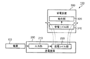
図1は、第1実施形態に従う非接触式の電力伝送システム100の機能構成を表す概略的なブロック図である。図1を参照して、電力伝送システム100が説明される。尚、図1において、実線の矢印は、電気エネルギの伝達を表す。点線の矢印は、磁束を概念的に表す。
<First Embodiment>
FIG. 1 is a schematic block diagram showing a functional configuration of a contactless
電力伝送システム100は、送電装置200と、受電装置300と、を備える。送電装置200は、電源ESから電力を受ける。その後、送電装置200は、電力を用いて、交番磁束を発生させる。交番磁束は、受電装置300内で誘起電流を生じさせる。受電装置300は、交番磁束に応じた誘起電流によって取得された電力を用いて、所定の動作を行うことができる。
The
送電装置200は、入力部210と、送電コイル部220と、を備える。電力は、電源ESから入力部210に入力される。その後、電力は、入力部210から送電コイル部220へ伝達される。送電コイル部220は、電力の供給に応じて、交番磁束を発生させる。
The
受電装置300は、受電コイル部310と、動作部320と、を備える。受電コイル部310は、送電コイル部220に磁気的に接続される。したがって、受電コイル部310は、送電コイル部220から発生された磁場の存在下で、誘起電流を生成する。動作部320は、誘起電流によって取得された電力を用いて、所定の動作を実行することができる。動作部320は、物体の変位を伴う動的な動作(例えば、物体の変位や振動)を行ってもよい。代替的に、動作部320は、物体の変位を伴わない静的な動作(例えば、蓄電)を行ってもよい。本実施形態の原理は、動作部320の動作によって、何ら限定されない。
The
図2Aは、送電コイル部220の概略的な平面図である。図2Bは、送電コイル部220の概略的な側面図である。図1乃至図2Bを参照して、送電コイル部220が説明される。
FIG. 2A is a schematic plan view of the power
送電コイル部220は、磁性材料から形成された磁性板221と、磁性板221上で略円環状に巻かれた巻線222と、を備える。送電コイル部220は、実質的に、平面コイルとして機能する。
The power
電力は、入力部210を通じて、巻線222に伝達される。電流は、磁性板221上で略円環状に巻かれた巻線222を流れるので、送電コイル部220は、強い磁場を発生することができる。
The electric power is transmitted to the winding 222 through the
図3Aは、受電コイル部310の概略的な斜視図である。図3Bは、受電コイル部310の概略的な底面図である。図1、図3A及び図3Bを参照して、受電コイル部310が説明される。
FIG. 3A is a schematic perspective view of the power receiving
受電コイル部310は、磁性材料から形成された略円筒状の磁性筒330と、磁性筒330の周面に螺旋状に巻き付けられた巻線311と、を備える。巻線311は、動作部320に電気的に接続される第1端部312と、第1端部312とは反対の第2端部313と、を含む。第1端部312及び第2端部313は、動作部320として用いられる回路基板(図示せず)に接続されてもよい。本実施形態において、磁性筒330は、筒状の磁性体として例示される。
The power
巻線311は、磁性筒330に巻き付けられる。この結果、受電コイル部310が曝される磁場が弱くても、巻線311には高い誘起電流が流れる。したがって、受電コイル部310は、送電コイル部220から離間されてもよい。
The winding 311 is wound around the
図4Aは、磁性筒330の概略的な斜視図である。図4Bは、磁性筒330の概略的な底面図である。図1、図4A及び図4Bを参照して、磁性筒330が説明される。
FIG. 4A is a schematic perspective view of the
略円筒状の磁性筒330は、略円柱状の内部空間ISを規定する。動作部320は、内部空間IS内に収容されてもよい。
The substantially cylindrical
本実施形態において、磁性体として例示される磁性筒330は、略円筒形状である。代替的に、磁性体は、他の形状を有してもよい。例えば、磁性体は、楕円筒であってもよいし、或いは、曲面で形成される周面を有する他の筒部材であってもよい。磁性体の形状や大きさは、送電コイル部の形状や大きさに応じて、適切に決定されてもよい。
In the present embodiment, the
<第2実施形態>
第1実施形態において、略円筒状の磁性筒が磁性体として例示されている。代替的に、磁性体は、角筒であってもよい。本実施形態において、角筒状の磁性体を利用した電力伝送システムが説明される。
Second Embodiment
In the first embodiment, a substantially cylindrical magnetic cylinder is exemplified as the magnetic body. Alternatively, the magnetic body may be a square tube. In the present embodiment, a power transmission system using a rectangular cylindrical magnetic material will be described.
図5は、第2実施形態に従う非接触式の電力伝送システム100Aの機能構成を表す概略的なブロック図である。図5を参照して、電力伝送システム100Aが説明される。尚、図5において、実線の矢印は、電気エネルギの伝達を表す。点線の矢印は、磁束を概念的に表す。第1実施形態と同一の要素に対して、同一の符号が付されている。第1実施形態に関連する説明は、同一の符号が付された要素に対して適用される。
FIG. 5 is a schematic block diagram showing a functional configuration of a contactless
電力伝送システム100Aは、送電装置200Aと、受電装置300Aと、を備える。送電装置200Aは、電源ESから電力を受ける。その後、送電装置200Aは、電力を用いて、磁束を発生させる。磁束は、受電装置300A内で誘起電流を生じさせる。受電装置300Aは、誘起電流によって取得された電力を用いて、所定の動作を行うことができる。
The
第1実施形態と同様に、送電装置200Aは、入力部210を備える。送電装置200Aは、送電コイル部220Aを更に備える。電力は、電源ESから入力部210に入力される。その後、電力は、入力部210から送電コイル部220Aへ伝達される。送電コイル部220Aは、電力の供給に応じて、磁場を作り出す。
Similarly to the first embodiment, the
第1実施形態と同様に、受電装置300Aは、動作部320を備える。受電装置300Aは、受電コイル部310Aを更に備える。受電コイル部310Aは、送電コイル部220Aに磁気的に接続される。したがって、受電コイル部310Aは、送電コイル部220Aから発生した磁場の存在下で、誘起電流を生成する。動作部320は、誘起電流によって取得された電力を用いて、所定の動作を実行することができる。動作部320は、物体の変位を伴う動的な動作(例えば、物体の変位や振動)を行ってもよい。代替的に、動作部320は、物体の変位を伴わない静的な動作(例えば、蓄電)を行ってもよい。本実施形態の原理は、動作部320の動作によって、何ら限定されない。
Similar to the first embodiment, the
図6Aは、送電コイル部220Aの概略的な平面図である。図6Bは、送電コイル部220Aの概略的な側面図である。図5乃至図6Bを参照して、送電コイル部220Aが説明される。
FIG. 6A is a schematic plan view of power
第1実施形態と同様に、送電コイル部220Aは、磁性材料から形成された磁性板221を備える。送電コイル部220Aは、磁性板221上に配置された巻線222Aを更に備える。第1実施形態とは異なり、巻線222Aは、矩形環を描く。送電コイル部220Aは、実質的に、平面コイルとして機能する。
Similar to the first embodiment, the power
電力は、入力部210を通じて、巻線222Aに伝達される。電流は、磁性板221上で略四角環状に巻かれた巻線222Aを流れるので、送電コイル部220Aは、強い磁場を発生することができる。
The electric power is transmitted to the winding 222 </ b> A through the
図7Aは、受電コイル部310Aの概略的な斜視図である。図7Bは、受電コイル部310Aの概略的な底面図である。図5、図7A及び図7Bを参照して、受電コイル部310Aが説明される。
FIG. 7A is a schematic perspective view of power receiving
第1実施形態と同様に、受電コイル部310Aは、巻線311を備える。受電コイル部310Aは、磁性材料から形成された磁性筒330Aを更に備える。磁性筒330Aは、四角筒である。巻線311は、磁性筒330Aの周面に螺旋状に巻き付けられる。この結果、受電コイル部310Aが曝される磁場が弱くても、受電コイル部310A内には高い誘起電流が発生する。したがって、受電コイル部310Aは、送電コイル部220Aから離間されてもよい。本実施形態において、磁性筒330Aは、筒状の磁性体として例示される。
Similarly to the first embodiment, the power receiving
図8Aは、磁性筒330Aの概略的な斜視図である。図8Bは、磁性筒330Aの概略的な底面図である。図5、図8A及び図8Bを参照して、磁性筒330Aが説明される。
FIG. 8A is a schematic perspective view of the
略角筒状の磁性筒330Aは、略四角柱状の内部空間ISAを規定する。動作部320は、内部空間ISA内に収容されてもよい。
The substantially rectangular cylindrical
本実施形態において、磁性体として例示される磁性筒330Aは、四角筒である。代替的に、磁性体は、他の形状を有してもよい。例えば、磁性体は、三角筒であってもよいし、或いは、他の多角筒であってもよい。磁性体の形状や大きさは、送電コイル部の形状や大きさに応じて、適切に決定されてもよい。
In the present embodiment, the
本実施形態において、磁性筒330Aの形状は、送電コイル部220Aの形状に合致している。この場合、磁性筒330Aが送電コイル部220Aに近接されるならば、電流は、受電コイル部310Aに効率的に誘起される。しかしながら、磁性筒は、送電コイル部に形状的に合致されなくともよい。例えば、第1実施形態に関連して説明された送電コイル部220によって作り出された磁場に磁性筒330Aが曝されてもよい。
In the present embodiment, the shape of the
<第3実施形態>
本実施形態において、第1実施形態の原理に基づいて設計された回路が説明される。尚、本実施形態において説明される回路は、例示的である。したがって、既知の電気技術に基づいて設計された他の回路が用いられてもよい。
<Third Embodiment>
In the present embodiment, a circuit designed based on the principle of the first embodiment will be described. Note that the circuits described in the present embodiment are illustrative. Thus, other circuits designed based on known electrical technology may be used.
図9は、送電装置200の概略的な回路図である。図9を参照して、送電装置200が説明される。
FIG. 9 is a schematic circuit diagram of the
入力部210は、フルブリッジ回路211と、制御IC212と、共振コンデンサ213と、を備える。フルブリッジ回路211は、4つの電界効果トランジスタ(図9において、記号「FET1」、「FET2」、「FET3」及び「FET4」を用いて示されている)を備える。本実施形態において、フルブリッジ回路211は、18Vの電圧の印加を受ける。制御IC212は、FET1とFET4とからなる組及びFET2とFET3とからなる組を交互にオン・オフする。共振コンデンサ213は、巻線222と協働して、共振回路を形成する。制御IC212によるオン・オフ制御の結果、共振コンデンサ213と巻線222とに高い周波数の交流電流が流れる。本実施形態において、交流電流の周波数は、400kHzである。巻線222の巻数は、10ターンである。これらの設計的な数値は、本実施形態の原理を何ら限定しない。
The
図10は、受電コイル部310に対向して配置された送電コイル部220の概略的な斜視図である。図1、図9及び図10を参照して、送電装置200が更に説明される。
FIG. 10 is a schematic perspective view of the power
磁性板221は、上面223を含む。巻線222は、上面223に形成される。磁性板221は、アモルファスの磁性シートであってもよい。
The
巻線222を流れる交流電流は、上面223の周囲に広がる磁界を作り出す。磁界は、受電コイル部310の巻線311に電流を誘起する。電流の誘起によって取得された電力は、動作部320の動作に利用される。
The alternating current flowing through the winding 222 creates a magnetic field that extends around the
共振コンデンサ213の静電容量「C」は、以下の数式に基づいて、決定されてもよい。
The capacitance “C” of the

上述の数式中のパラメータ「f」は、巻線222を流れる交流電流の周波数である。上述の数式中のパラメータ「L」は、磁性板221の特性と巻線222の特性とによって定められるインダクタンスである。
The parameter “f” in the above formula is the frequency of the alternating current flowing through the winding 222. The parameter “L” in the above equation is an inductance determined by the characteristics of the
磁性筒330は、フェライトから形成される。磁性筒330の外径は、「φ20mm」である。磁性筒330の内径は、「φ18mm」である。磁性筒330の長さは、「135mm」である。巻線311の巻数は、130ターンである。これらの設計的な数値は、本実施形態の原理を何ら限定しない。
The
図11は、受電装置300の概略的な回路図である。図1、図9乃至図11を参照して、受電装置300が説明される。
FIG. 11 is a schematic circuit diagram of the
図1を参照して説明された如く、受電装置300は、受電コイル部310と、動作部320と、を備える。図11には、動作部320として用いられるモータ321が示されている。
As described with reference to FIG. 1, the
受電装置300は、巻線311を流れる交流電流を直流電流に変換する変換回路340を備えてもよい。変換回路340は、共振コンデンサ341と、整流ブリッジ回路342と、平滑コンデンサ343と、を備える。共振コンデンサ341は、巻線311と協働して共振回路を形成する。受電装置300内の共振回路(共振コンデンサ341、巻線311及び磁性筒330)の共振周波数が、送電装置200内の共振回路(共振コンデンサ213、巻線222及び磁性板221)の共振周波数に合致するように、共振コンデンサ341の静電容量は、設定される。
The
整流ブリッジ回路342は、4つのダイオード(図11中、記号「D1」、「D2」、「D3」及び「D4」で表されている)を含む。整流ブリッジ回路342は、受電コイル部310内で誘起された交流電流を整流する。本実施形態において、整流ブリッジ回路342は、整流部として例示される。
The
平滑コンデンサ343は、整流ブリッジ回路342によって整流された電流から電荷を蓄える。平滑コンデンサ343は、電荷を直流電流として、モータ321に出力する。この結果、モータ321は、駆動される。
The smoothing
<第4実施形態>
第3実施形態において、動作部として用いられるモータは、変換回路によって生成された直流電流を直接的に受け取る。代替的に、動作部は、蓄電機能を有してもよい。モータは、蓄えられた電力を用いて、動作してもよい。本実施形態において、蓄電機能を有する動作部を含む受電装置が説明される。
<Fourth embodiment>
In the third embodiment, the motor used as the operating unit directly receives the direct current generated by the conversion circuit. Alternatively, the operating unit may have a power storage function. The motor may operate using the stored power. In the present embodiment, a power receiving device including an operation unit having a power storage function is described.
図12は、受電装置300Bの概略的な回路図である。図12を参照して、受電装置300Bが説明される。第3実施形態と同一の要素に対して、同一の符号が付されている。第3実施形態に関連する説明は、同一の符号が付された要素に援用される。
FIG. 12 is a schematic circuit diagram of the
第3実施形態と同様に、受電装置300Bは、受電コイル部310と、変換回路340と、を備える。受電装置300Bは、動作部320Bを更に備える。
Similarly to the third embodiment, the
第3実施形態と同様に、動作部320Bは、モータ321を備える。動作部320Bは、モータ321と平滑コンデンサ343との間で、電気的に接続された2次電池322を更に備える。直流電流は、平滑コンデンサ343から2次電池322に出力される。この結果、2次電池322は、蓄電することができる。モータ321は、2次電池322に蓄えられた電力を消費し、動作することができる。
Similar to the third embodiment, the
<第5実施形態>
本実施形態において、第4実施形態に関連して説明された原理に基づいて構築された電動歯ブラシが説明される。本実施形態において、電動歯ブラシは、受電装置として機能する。
<Fifth Embodiment>
In the present embodiment, an electric toothbrush constructed based on the principle described in relation to the fourth embodiment will be described. In the present embodiment, the electric toothbrush functions as a power receiving device.
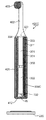
図13は、第5実施形態の電動歯ブラシ(以下、「歯ブラシ400」と称される)の概略的な斜視図である。図12及び図13を参照して、歯ブラシ400が説明される。第4実施形態と同一の要素に対して、同一の符号が付されている。第4実施形態に関連する説明は、同一の符号が付された要素に援用される。
FIG. 13 is a schematic perspective view of an electric toothbrush (hereinafter referred to as “
歯ブラシ400は、下筐体401と、上筐体402と、ブラシ部403と、を備える。上筐体402は、下筐体401よりも細い。使用者は、下筐体401を握持し、上筐体402を口腔内に挿入することができる。この結果、ブラシ部403は、使用者の歯に当接される。
The
巻線311、モータ321、磁性筒330、2次電池322及び変換回路340は、下筐体401内に主に収容される。モータ321からブラシ部403へ伝達するための伝達機構(図示せず)は、上筐体402内に収容される。モータ321からブラシ部403への駆動力の伝達の結果、ブラシ部403は、歯を洗浄するように動作することができる。本実施形態において、下筐体401は、筐体として例示される。
The winding 311, the
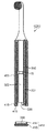
図14は、歯ブラシ400の概略的な部分断面図である。図12及び図14を参照して、歯ブラシ400が更に説明される。
FIG. 14 is a schematic partial cross-sectional view of the
下筐体401は、筒状の周壁411と、周壁411の下端に接続される底壁412と、を含む。周壁411は、底壁412と上筐体402との間で、巻線311、モータ321、磁性筒330、2次電池322及び変換回路340を収容するための収容空間を規定する。
The
磁性筒330は、収容空間内に挿入される。巻線311は、周壁411と磁性筒330との間に配置される。
The
第1実施形態に関連して説明された如く、磁性筒330は、内部空間ISを形成する。モータ321、2次電池322及び変換回路340が構築された回路基板350は、内部空間IS内に配置される。モータ321、2次電池322及び回路基板350は、磁性筒330内に配置されるので、下筐体401の設計は、過度に大きくならない。加えて、磁性筒330は、モータ321、2次電池322及び回路基板350を取り囲むので、巻線311に流れる交流電流に起因して生じた磁束は、モータ321、2次電池322及び回路基板350に影響を与えにくい。したがって、モータ321、2次電池322及び回路基板350の意図しない加熱や誤動作は生じにくくなる。
As described in relation to the first embodiment, the
<第6実施形態>
磁性筒は、動作部を内部空間に閉じ込めるように設計されてもよい。本実施形態において、モータ及び2次電池を内部空間に閉じ込めることができる磁性体を備える電動歯ブラシが説明される。
<Sixth Embodiment>
The magnetic cylinder may be designed to confine the operating part in the internal space. In the present embodiment, an electric toothbrush provided with a magnetic body capable of confining a motor and a secondary battery in an internal space will be described.
図15は、歯ブラシ400Cの概略的な部分断面図である。図15を参照して、歯ブラシ400Cが更に説明される。第5実施形態と同一の要素に対して、同一の符号が付されている。第5実施形態に関連する説明は、同一の符号が付された要素に援用される。
FIG. 15 is a schematic partial cross-sectional view of the
第5実施形態と同様に、歯ブラシ400Cは、下筐体401と、上筐体402と、ブラシ部403と、巻線311と、モータ321と、2次電池322と、回路基板350と、を備える。歯ブラシ400Cは、磁性筒330Cを更に備える。磁性筒330Cは、モータ321、2次電池322及び回路基板350を収容する内部空間ISを規定する筒部331を含む。筒部331は、下筐体401の底壁412に対向する下端部332と、下端部332とは反対側の上端部333と、を含む。磁性筒330Cは、上端部333が規定する上側開口部を部分的に閉塞する上片334を含む。モータ321は、上片334を超えて上方に突出するシャフト323を備える。シャフト323は、モータ321からブラシ部403へ伝達するための伝達機構(図示せず)に接続される。本実施形態において、下端部332は、第1端部として例示される。上片334は、第2壁部として例示される。
As in the fifth embodiment, the
図15に示される如く、典型的には、底壁412が送電コイル部220に対向するように、歯ブラシ400Cは、配置される。この結果、上端部333は、下端部332よりも送電コイル部220から離間する。本実施形態において、上端部333は、第2端部として例示される。
As shown in FIG. 15, the
モータ321、2次電池322及び回路基板350は、底壁412によって支持される。上片334は、上端部333が規定する上側開口部を部分的に閉じる。したがって、上片334は、底壁412と協働して、モータ321、2次電池322及び回路基板350を内部空間IS内に閉じ込めることができる。本実施形態において、上側開口部は、第2開口部として例示される。
The
本実施形態において、第2壁部として例示される上片334は、上側開口部を部分的に閉じる。代替的に、第2壁部は、筒部が規定する開口部を完全に閉塞してもよい。第2壁部の形状は、受電装置の設計に基づいて、適切に決定されてもよい。
In the present embodiment, the
<第7実施形態>
磁性筒は、送電コイル部からの交番磁束を効果的に受けるように設計されることが好ましい。本実施形態において、交番磁束を効果的に受けることができる磁性筒を備える電動歯ブラシが説明される。
<Seventh embodiment>
The magnetic cylinder is preferably designed so as to effectively receive the alternating magnetic flux from the power transmission coil section. In the present embodiment, an electric toothbrush including a magnetic cylinder that can effectively receive an alternating magnetic flux is described.
図16は、歯ブラシ400Dの概略的な部分断面図である。図16を参照して、歯ブラシ400Dが更に説明される。第6実施形態と同一の要素に対して、同一の符号が付されている。第6実施形態に関連する説明は、同一の符号が付された要素に援用される。
FIG. 16 is a schematic partial cross-sectional view of the
第6実施形態と同様に、歯ブラシ400Dは、下筐体401と、上筐体402と、ブラシ部403と、巻線311と、モータ321と、2次電池322と、回路基板350と、を備える。歯ブラシ400Dは、磁性筒330Dを更に備える。
As in the sixth embodiment, the
第6実施形態と同様に、磁性筒330Dは、筒部331と、上片334と、を含む。磁性筒330Dは、筒部331の下端部332が規定する下側開口部を閉塞する下片335を更に含む。上端部333を部分的に閉じる上片334とは異なり、下片335は、上端部333よりも送電コイル部220に近い下端部332を閉じる。したがって、下片335は、送電コイル部220と2次電池322との間に配置される。この結果、下片335は、送電コイル部220から発生した交番磁束に効果的に曝される。加えて、下片335が存在するので、送電コイル部220から発生した交番磁束は、モータ321、2次電池322や回路基板350に影響しにくくなる。本実施形態において、下片335は、第1壁部として例示される。下側開口部は、第1開口部として例示される。
Similar to the sixth embodiment, the
本実施形態において、第1壁部として例示される下片335は、下端部332を閉じる。代替的に、第1壁部は、下端部と上端部との間において、筒部が規定する内部空間を仕切ってもよい。
In the present embodiment, the
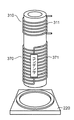
図17は、歯ブラシ400Dの概略的な分解図である。図17を参照して、歯ブラシ400Dが更に説明される。
FIG. 17 is a schematic exploded view of the
下片335は、底壁412に固定される一方で、筒部331から分離可能である。底壁412は、下片335が取り付けられる取付板413と、取付板413から周壁411に向けて突出する円筒状の雄螺子部414と、を含む。周壁411は、雌螺子部415が形成された下端部416を含む。雄螺子部414は、雌螺子部415に螺合される。
The
使用者は、底壁412を周壁411から分離することができる。この結果、筒部331の下側開口部336は、開放される。使用者は、下側開口部336を通じて、モータ321、2次電池322及び回路基板350を内部空間IS内に挿入することができる。
The user can separate the
本実施形態において、第1壁部として例示される下片335は、筒部331から分離可能である。代替的に、第1壁部は、筒部と一体的に形成されてもよい。
In the present embodiment, the
<第8実施形態>
第7実施形態において、下片は、下側開口部を完全に閉塞する。代替的に、下片は、下側開口部を部分的に閉塞してもよい。下側開口部が、下片によって部分的に閉塞されるならば、巻線は、回路基板に下片を通じて電気的に接続される。
<Eighth Embodiment>
In the seventh embodiment, the lower piece completely closes the lower opening. Alternatively, the lower piece may partially occlude the lower opening. If the lower opening is partially occluded by the lower piece, the winding is electrically connected to the circuit board through the lower piece.
図18は、歯ブラシ400Eの概略的な部分断面図である。図18を参照して、歯ブラシ400Eが更に説明される。第7実施形態と同一の要素に対して、同一の符号が付されている。第7実施形態に関連する説明は、同一の符号が付された要素に援用される。
FIG. 18 is a schematic partial cross-sectional view of the
第7実施形態と同様に、歯ブラシ400Eは、上筐体402と、ブラシ部403と、巻線311と、モータ321と、2次電池322と、回路基板350と、を備える。歯ブラシ400Eは、下筐体401Eと、磁性筒330Eと、を更に備える。
Similar to the seventh embodiment, the
第7実施形態と同様に、下筐体401Eは、周壁411を含む。下筐体401Eは、底壁412Eを更に含む。第7実施形態と同様に、底壁412Eは、周壁411に螺合される雄螺子部414を含む。底壁412Eは、取付板413Eを更に含む。雄螺子部414は、取付板413Eから突出する。第7実施形態とは異なり、取付板413Eには凹部417が形成される。
Similarly to the seventh embodiment, the
第7実施形態と同様に、磁性筒330Eは、筒部331と、上片334と、を含む。磁性筒330Eは、筒部331の下端部332が規定する下側開口部を部分的に閉塞する下片335Eを更に含む。下片335Eは、下側開口部を完全に閉じないので、凹部417は、内部空間ISと連通する。
Similar to the seventh embodiment, the
モータ321、2次電池322及び回路基板350は、磁性筒330E内に配置される一方で、巻線311は、磁性筒330Eの外に配置される。凹部417は、内部空間ISに連通するので、巻線311から回路基板350への配線は、凹部417を通じて、適切に形成される。
The
<第9実施形態>
筒部は、複数の部材から形成されてもよい。筒部が、複数の部材から形成されるならば、電力の伝送効率は向上される。本実施形態において、複数の部材から形成された筒部を備える電動歯ブラシが説明される。
<Ninth Embodiment>
The tube portion may be formed from a plurality of members. If the cylindrical portion is formed of a plurality of members, the power transmission efficiency is improved. In this embodiment, an electric toothbrush provided with the cylinder part formed from the several member is demonstrated.
図19は、歯ブラシ400Fの概略的な部分断面図である。図19を参照して、歯ブラシ400Fが更に説明される。第7実施形態と同一の要素に対して、同一の符号が付されている。第7実施形態に関連する説明は、同一の符号が付された要素に援用される。
FIG. 19 is a schematic partial cross-sectional view of the
第7実施形態と同様に、歯ブラシ400Fは、下筐体401と、上筐体402と、ブラシ部403と、巻線311と、モータ321と、2次電池322と、回路基板350と、を備える。歯ブラシ400Fは、磁性筒330Fを更に備える。
Similar to the seventh embodiment, the
第7実施形態と同様に、磁性筒330Fは、上片334と、下片335と、を含む。磁性筒330Fは、筒部331Fを更に含む。筒部331Fは、上片334が取り付けられた上筒片337と、下片335によって閉塞される下筒片338と、上筒片337と下筒片338との間に配置された中筒片339と、を含む。上筒片337、下筒片338及び中筒片339は、下筐体401の軸に沿って整列される。本実施形態において、上筒片337、下筒片338及び中筒片339のうち1つは、第1筒部として例示される。上筒片337、下筒片338及び中筒片339のうち他のもう1つは、第2筒部として例示される。
Similar to the seventh embodiment, the
電力の伝送効率を表すQ値は、以下の数式によって表される。 The Q value representing the power transmission efficiency is expressed by the following mathematical formula.
上述の数式中のパラメータ「Q」は、Q値である。上述の数式中のパラメータ「f」は、上述の数1によって与えられる。上述の数式中のパラメータ「L」は、インダクタンスである。インダクタンスは、上筒片337、下筒片338及び中筒片339の配置や設計に応じて変化する。上述の数式中のパラメータ「r」は、交流抵抗である。交流抵抗は、上筒片337、下筒片338及び中筒片339の配置や設計に応じて変化する。
The parameter “Q” in the above formula is a Q value. The parameter “f” in the above equation is given by the above equation 1. The parameter “L” in the above formula is an inductance. The inductance changes depending on the arrangement and design of the
本実施形態において、上筒片337、下筒片338及び中筒片339は、「45mm」の長さにそれぞれ設計される。上筒片337、下筒片338及び中筒片339それぞれは、「20mm」の外径及び「18mm」の内径を有するフェライト製の円筒である。
In the present embodiment, the
以下の表は、上筒片337、下筒片338及び中筒片339の配置に応じたQ値の変化を表す。
The following table shows changes in the Q value according to the arrangement of the
上筒片337、中筒片339及び下筒片338の間に空隙が形成される結果(条件1)、空隙が形成されない条件2と較べて、インダクタンスは小さくなる一方で、交流抵抗は小さくなる。上述の数式において、分母として機能する交流抵抗値の低下のQ値への影響は、分子として作用するインダクタンス値の影響よりも大きい。したがって、条件1は、条件2よりも大きなQ値をもたらすことができる。
As a result of the gap being formed between the
<第10実施形態>
第9実施形態に関連して説明された如く、上筒片、中筒片及び下筒片の間の空隙に応じて、Q値は変動する。したがって、上筒片、中筒片及び下筒片の間の空隙寸法は、適切に維持されることが好ましい。本実施形態において、上筒片、中筒片及び下筒片の間の空隙寸法を維持するための技術が説明される。
<Tenth Embodiment>
As described in relation to the ninth embodiment, the Q value varies depending on the gaps between the upper cylinder piece, the middle cylinder piece, and the lower cylinder piece. Therefore, it is preferable that the space | gap dimension between an upper cylinder piece, a middle cylinder piece, and a lower cylinder piece is maintained appropriately. In the present embodiment, a technique for maintaining the gap size between the upper cylinder piece, the middle cylinder piece, and the lower cylinder piece will be described.
図20は、歯ブラシ400Gの概略的な部分断面図である。図20を参照して、歯ブラシ400Gが更に説明される。第9実施形態と同一の要素に対して、同一の符号が付されている。第9実施形態に関連する説明は、同一の符号が付された要素に援用される。
FIG. 20 is a schematic partial cross-sectional view of the
第9実施形態と同様に、歯ブラシ400Gは、下筐体401と、上筐体402と、ブラシ部403と、磁性筒330Fと、巻線311と、モータ321と、2次電池322と、回路基板350と、を備える。歯ブラシ400Gは、上筒片337と中筒片339とを接合する上接合部351と、下筒片338と中筒片339とを接合する下接合部352と、を更に備える。上接合部351は、上筒片337と中筒片339との間の空隙を維持する。下接合部352は、下筒片338と中筒片339との間の空隙を維持する。上接合部351及び下接合部352は、非磁性材料から形成される。この結果、第9実施形態の原理に従って、高いQ値が達成される。加えて、歯ブラシ400Gに外力が加わっている間、上筒片337と中筒片339との間の衝突及び下筒片338と中筒片339との間の衝突は生じにくくなる。したがって、歯ブラシ400Gの機械的強度は高くなる。上接合部351及び下接合部352は、ABS樹脂から形成されてもよい。本実施形態において、上接合部351及び下接合部352は、スペーサとして例示される。
Similar to the ninth embodiment, the
<第11実施形態>
上筒片、中筒片及び下筒片は、他の技術によって固定されてもよい。本実施形態において、上筒片、中筒片及び下筒片を固定するための他の技術が説明される。
<Eleventh embodiment>
The upper cylinder piece, the middle cylinder piece, and the lower cylinder piece may be fixed by other techniques. In this embodiment, another technique for fixing the upper cylinder piece, the middle cylinder piece, and the lower cylinder piece will be described.
図21は、歯ブラシ400Hの概略的な部分断面図である。図21を参照して、歯ブラシ400Hが更に説明される。第9実施形態と同一の要素に対して、同一の符号が付されている。第9実施形態に関連する説明は、同一の符号が付された要素に援用される。
FIG. 21 is a schematic partial cross-sectional view of the
第9実施形態と同様に、歯ブラシ400Hは、下筐体401と、上筐体402と、ブラシ部403と、巻線311と、モータ321と、2次電池322と、回路基板350と、を備える。歯ブラシ400Hは、磁性筒330Hと、ボビン360と、を備える。
Similar to the ninth embodiment, the
第9実施形態と同様に、磁性筒330Hは、上片334と、下片335と、を含む。磁性筒330Hは、上片334によって部分的に閉じられる上筒片337Hと、下片335によって閉じられる下筒片338Hと、を更に含む。上筒片337H及び下筒片338Hは、下筐体401内で整列される。ボビン360は、上筒片337H/下筒片338Hと巻線311との間に配置される。
Similar to the ninth embodiment, the
図22は、上筒片337Hと下筒片338Hとの間における歯ブラシ400Hの拡大断面図である。図21及び図22を参照して、歯ブラシ400Hが説明される。
FIG. 22 is an enlarged cross-sectional view of the
ボビン360は、上筒片337H及び下筒片338Hと相補的な筒体である。巻線311は、ボビン360の外周面に巻き付けられる。
The
図23は、歯ブラシ400Hの概略的な断面図である。尚、図23において、上筒片337H及び下筒片338Hは、歯ブラシ400Hから除去されている。図21乃至図23を参照して、歯ブラシ400Hが説明される。
FIG. 23 is a schematic cross-sectional view of the
ボビン360は、巻線311が巻かれた外周面とは反対側の内周面から突出する突環361を含む。突環361は、上筒片337Hと下筒片338Hとの間に挿入される。したがって、上筒片337Hは、突環361と上片334との間で固定される。下筒片338Hは、突環361と下片335との間で固定される。
The
<第12実施形態>
送電コイル部からの交番磁束に応じて共振する共振回路部が用いられるならば、受電装置と送電装置との距離が長くなっても、送電装置から受電装置への電力の伝送は効率的に行われる。本実施形態において、共振回路部を備える受電装置が説明される。
<Twelfth embodiment>
If a resonance circuit unit that resonates according to the alternating magnetic flux from the power transmission coil unit is used, power transmission from the power transmission device to the power reception device can be performed efficiently even if the distance between the power reception device and the power transmission device is increased. Is called. In the present embodiment, a power receiving device including a resonance circuit unit is described.
図24は、受電装置300Iの概略的な回路図である。図9及び図24を参照して、受電装置300Iが説明される。第3実施形態と同一の要素に対して、同一の符号が付されている。第3実施形態に関連する説明は、同一の符号が付された要素に援用される。 FIG. 24 is a schematic circuit diagram of the power receiving device 300I. The power receiving device 300I is described with reference to FIGS. The same code | symbol is attached | subjected with respect to the element same as 3rd Embodiment. The description related to the third embodiment is applied to elements having the same reference numerals.
第3実施形態と同様に、受電装置300Iは、モータ321と、受電コイル部310と、を備える。受電装置300Iは、変換回路340Iを更に備える。第3実施形態と同様に、変換回路340Iは、整流ブリッジ回路342と、平滑コンデンサ343と、を備える。第3実施形態とは異なり、変換回路340Iは、共振コンデンサを有していない。
Similarly to the third embodiment, the power receiving device 300I includes a
受電装置300Iは、共振回路部370を更に備える。共振回路部370は、磁性筒330を取り巻く共振コイル371と、共振コイル371に電気的に接続された共振コンデンサ372と、を含む。共振コイル371及び共振コンデンサ372は、閉回路を形成し、モータ321、受電コイル部310及び変換回路340Iを含む電気回路から電気的に独立される(即ち、共振回路部370は、モータ321、受電コイル部310及び変換回路340Iとは電気的接点を有さない)。共振回路部370は、送電装置200が作り出す交番磁束に共振するように設計される。この結果、受電コイル部310に電流が効率的に誘起される。
The power receiving device 300I further includes a
図25は、送電コイル部220、共振回路部370及び受電コイル部310の間の位置関係を表す概略図である。図25を参照して、送電コイル部220、共振回路部370及び受電コイル部310の間の位置関係が説明される。
FIG. 25 is a schematic diagram illustrating a positional relationship among the power
共振回路部370は、送電コイル部220と受電コイル部310との間に配置される。共振回路部370は、送電コイル部220と受電コイル部310とに磁気的にそれぞれ接続される。本実施形態において、共振コイル371の巻数は、80ターンである。受電コイル部310の巻線311の巻数は、5ターンである。
The
<第13実施形態>
第12実施形態において、動作部として用いられるモータは、変換回路によって生成された直流電流を直接的に受け取る。代替的に、動作部は、蓄電機能を有してもよい。モータは、蓄えられた電力を用いて、動作してもよい。本実施形態において、蓄電機能を有する動作部を含む受電装置が説明される。
<13th Embodiment>
In the twelfth embodiment, the motor used as the operating unit directly receives the direct current generated by the conversion circuit. Alternatively, the operating unit may have a power storage function. The motor may operate using the stored power. In the present embodiment, a power receiving device including an operation unit having a power storage function is described.
図26は、受電装置300Jの概略的な回路図である。図26を参照して、受電装置300Jが説明される。第12実施形態と同一の要素に対して、同一の符号が付されている。第12実施形態に関連する説明は、同一の符号が付された要素に援用される。
FIG. 26 is a schematic circuit diagram of the
第12実施形態と同様に、受電装置300Jは、受電コイル部310と、変換回路340Iと、共振回路部370と、モータ321と、を備える。受電装置300Jは、モータ321と平滑コンデンサ343との間で、電気的に接続された2次電池322を更に備える。直流電流は、平滑コンデンサ343から2次電池322に出力される。この結果、2次電池322は、蓄電することができる。モータ321は、2次電池322に蓄えられた電力を消費し、動作することができる。
Similarly to the twelfth embodiment, the
<第14実施形態>
磁性筒は、動作部を部分的に収容してもよい。この結果、受電装置は、軽量化される。本実施形態において、動作部を部分的に収容する磁性筒を備える電動歯ブラシが説明される。
<Fourteenth embodiment>
The magnetic cylinder may partially accommodate the operating part. As a result, the power receiving device is reduced in weight. In the present embodiment, an electric toothbrush provided with a magnetic cylinder that partially accommodates the operating portion will be described.
図27は、歯ブラシ400Kの概略的な部分断面図である。図27を参照して、歯ブラシ400Kが更に説明される。第5実施形態と同一の要素に対して、同一の符号が付されている。第5実施形態に関連する説明は、同一の符号が付された要素に援用される。
FIG. 27 is a schematic partial cross-sectional view of the
第5実施形態と同様に、歯ブラシ400Kは、下筐体401と、上筐体402と、ブラシ部403と、巻線311と、モータ321と、2次電池322と、回路基板350と、を備える。歯ブラシ400Kは、磁性筒330Kを更に備える。
Similar to the fifth embodiment, the
2次電池322は、磁性筒330Kの内部に収容される一方で、モータ321は、磁性筒330Kから露出している。モータ321は、下筐体401に固定されてもよい。
The
本実施形態の原理は、長距離の電力伝送を要求する様々な装置に好適に利用される。特に、本実施形態の原理は、電動歯ブラシや他の小型電動装置に好適に利用される。 The principle of this embodiment is suitably used for various devices that require long-distance power transmission. In particular, the principle of this embodiment is suitably used for an electric toothbrush and other small electric devices.
100,100A・・・・・・・・・・・電力伝送システム
220,220A・・・・・・・・・・・送電コイル部
310,310A・・・・・・・・・・・受電コイル部
311・・・・・・・・・・・・・・・・巻線
320,320B・・・・・・・・・・・動作部
330・・・・・・・・・・・・・・・・磁性筒
330A・・・・・・・・・・・・・・・磁性筒
330C・・・・・・・・・・・・・・・磁性筒
330D・・・・・・・・・・・・・・・磁性筒
330E・・・・・・・・・・・・・・・磁性筒
330F・・・・・・・・・・・・・・・磁性筒
330H・・・・・・・・・・・・・・・磁性筒
330K・・・・・・・・・・・・・・・磁性筒
331,331F・・・・・・・・・・・筒部
332・・・・・・・・・・・・・・・・下端部
333・・・・・・・・・・・・・・・・上端部
334・・・・・・・・・・・・・・・・上片
335,335E・・・・・・・・・・・下片
336・・・・・・・・・・・・・・・・下側開口部
337,337H・・・・・・・・・・・上筒片
338,338H・・・・・・・・・・・下筒片
339・・・・・・・・・・・・・・・・中筒片
342・・・・・・・・・・・・・・・・整流ブリッジ回路
351・・・・・・・・・・・・・・・・上接合部
352・・・・・・・・・・・・・・・・下接合部
361・・・・・・・・・・・・・・・・突環
370・・・・・・・・・・・・・・・・共振回路部
400・・・・・・・・・・・・・・・・歯ブラシ
400C・・・・・・・・・・・・・・・歯ブラシ
400D・・・・・・・・・・・・・・・歯ブラシ
400E・・・・・・・・・・・・・・・歯ブラシ
400F・・・・・・・・・・・・・・・歯ブラシ
400G・・・・・・・・・・・・・・・歯ブラシ
400H・・・・・・・・・・・・・・・歯ブラシ
400K・・・・・・・・・・・・・・・歯ブラシ
401,401E・・・・・・・・・・・下筐体
100, 100A ...
Claims (13)
前記送電コイル部に磁気的に結合し、前記交番磁束に応じた電流が誘起される受電コイル部と、を備え、
前記受電コイル部は、筒状の磁性体と、前記磁性体を取り巻く巻線と、を含むことを特徴とする非接触式の電力伝送システム。 A power transmission coil section for generating an alternating magnetic flux;
A power receiving coil unit that is magnetically coupled to the power transmission coil unit and in which a current corresponding to the alternating magnetic flux is induced;
The non-contact power transmission system, wherein the power receiving coil unit includes a cylindrical magnetic body and a winding surrounding the magnetic body.
前記第1壁部は、前記動作部と前記送電コイル部との間に配置されることを特徴とする請求項1に記載の電力伝送システム。 The magnetic body includes a cylindrical portion that defines an internal space that accommodates an operation portion that performs a predetermined operation by electric power acquired by the current, and a first wall portion that at least partially closes the internal space,
The power transmission system according to claim 1, wherein the first wall portion is disposed between the operation unit and the power transmission coil unit.
前記第1壁部は、前記第1端部が規定する第1開口部を少なくとも部分的に閉塞することを特徴とする請求項2に記載の電力伝送システム。 The tube portion includes a first end portion, and a second end portion that is further away from the power transmission coil portion than the first end portion,
The power transmission system according to claim 2, wherein the first wall portion at least partially closes a first opening defined by the first end portion.
前記磁性体は、前記電流によって取得された電力によって所定の動作をする動作部を収容する内部空間を規定する筒部と、前記内部空間を少なくとも部分的に閉じる第2壁部と、を含み、
前記第2壁部は、前記筐体と協働して、前記動作部を前記内部空間内に閉じ込めることを特徴とする請求項1に記載の電力伝送システム。 A housing that houses the power receiving coil section;
The magnetic body includes a cylindrical portion that defines an internal space that accommodates an operation portion that performs a predetermined operation by electric power acquired by the current, and a second wall portion that at least partially closes the internal space,
2. The power transmission system according to claim 1, wherein the second wall portion cooperates with the housing to confine the operating portion in the internal space.
前記第2壁部は、前記第2端部が規定する第2開口部を少なくとも部分的に閉塞することを特徴とする請求項5に記載の電力伝送システム。 The cylindrical portion includes a first end facing the housing, and a second end spaced away from the power transmission coil portion than the first end,
The power transmission system according to claim 5, wherein the second wall portion at least partially closes a second opening defined by the second end portion.
前記電力は、前記整流部を通過した前記電流によって取得されることを特徴とする請求項2乃至10のいずれか1項に記載の電力伝送システム。 A rectifier that rectifies the current flowing through the power receiving coil;
The power transmission system according to claim 2, wherein the power is acquired by the current that has passed through the rectifying unit.
前記共振回路部は、前記交番磁束に応じて共振し、前記共振回路部から電気的に独立された前記受電コイル部に前記電流を誘起することを特徴とする請求項1乃至11のいずれか1項に記載の電力伝送システム。 Between the power transmission coil unit and the power reception coil unit, further comprising a resonance circuit unit magnetically connected to the power reception coil unit,
The resonance circuit unit resonates according to the alternating magnetic flux, and induces the current in the power receiving coil unit that is electrically independent from the resonance circuit unit. The power transmission system according to item.
筒状の磁性体と、
前記電流が流れる巻線と、
前記電流によって取得された電力によって所定の動作をする動作部と、を備え、
前記磁性体は、前記動作部を収容する筒部を含み、
前記巻線は、前記筒部を取り巻くことを特徴とする受電装置。 A power receiving device in which a current according to an alternating magnetic flux is induced,
A cylindrical magnetic body,
A winding through which the current flows;
An operation unit that performs a predetermined operation with the electric power acquired by the current,
The magnetic body includes a cylindrical portion that houses the operating portion,
The power receiving device, wherein the winding surrounds the cylindrical portion.
Priority Applications (2)
| Application Number | Priority Date | Filing Date | Title |
|---|---|---|---|
| JP2013111777A JP2014233113A (en) | 2013-05-28 | 2013-05-28 | Non-contact power transmission system and power receiver |
| PCT/JP2014/001203 WO2014192201A1 (en) | 2013-05-28 | 2014-03-05 | Non-contact power transmission system, and power reception apparatus |
Applications Claiming Priority (1)
| Application Number | Priority Date | Filing Date | Title |
|---|---|---|---|
| JP2013111777A JP2014233113A (en) | 2013-05-28 | 2013-05-28 | Non-contact power transmission system and power receiver |
Publications (1)
| Publication Number | Publication Date |
|---|---|
| JP2014233113A true JP2014233113A (en) | 2014-12-11 |
Family
ID=51988256
Family Applications (1)
| Application Number | Title | Priority Date | Filing Date |
|---|---|---|---|
| JP2013111777A Pending JP2014233113A (en) | 2013-05-28 | 2013-05-28 | Non-contact power transmission system and power receiver |
Country Status (2)
| Country | Link |
|---|---|
| JP (1) | JP2014233113A (en) |
| WO (1) | WO2014192201A1 (en) |
Cited By (2)
| Publication number | Priority date | Publication date | Assignee | Title |
|---|---|---|---|---|
| KR20170013550A (en) * | 2015-07-28 | 2017-02-07 | 삼성전자주식회사 | Wireless power transmitter |
| JP2019059435A (en) * | 2017-09-28 | 2019-04-18 | 豊田合成株式会社 | Vehicular light-emitting device |
Citations (12)
| Publication number | Priority date | Publication date | Assignee | Title |
|---|---|---|---|---|
| JPS59218107A (en) * | 1983-05-25 | 1984-12-08 | 三洋電機株式会社 | Electromotive toothbrush |
| JPH0646531A (en) * | 1992-07-23 | 1994-02-18 | Mitsubishi Electric Home Appliance Co Ltd | Charger |
| JPH09173150A (en) * | 1995-12-25 | 1997-07-08 | Matsushita Electric Works Ltd | Motor-driven toothbrush device |
| JP2005124324A (en) * | 2003-10-17 | 2005-05-12 | Kami Electronics Ind Co Ltd | Non-contact type dry battery type charger |
| JP2007330404A (en) * | 2006-06-13 | 2007-12-27 | Olympus Corp | Wireless power supply system and capsule endoscope equipped with the same |
| JP2008301645A (en) * | 2007-06-01 | 2008-12-11 | Sanyo Electric Co Ltd | Non-contact power receiving apparatus and electronic apparatus therewith |
| WO2011114527A1 (en) * | 2010-03-19 | 2011-09-22 | 富士通株式会社 | Mobile telephone |
| JP2011210937A (en) * | 2010-03-30 | 2011-10-20 | Murata Mfg Co Ltd | Coil module and electronic device having the same |
| WO2012099170A1 (en) * | 2011-01-19 | 2012-07-26 | 株式会社 テクノバ | Contactless power transfer system |
| JP2012157219A (en) * | 2011-01-28 | 2012-08-16 | Hitachi Maxell Energy Ltd | Power receiving unit, and charging system and electric apparatus having the same |
| JP2012165635A (en) * | 2011-02-08 | 2012-08-30 | Tdk Corp | Wireless power reception device and wireless power transmission system |
| JP2012205379A (en) * | 2011-03-25 | 2012-10-22 | Sanyo Electric Co Ltd | Charging system, power supply device, mobile body, wireless power transmission and reception system, and power reception device |
Family Cites Families (2)
| Publication number | Priority date | Publication date | Assignee | Title |
|---|---|---|---|---|
| JP6095957B2 (en) * | 2012-04-17 | 2017-03-15 | 日東電工株式会社 | Wireless power transmission device, power feeding device, and power receiving device |
| JP2014017920A (en) * | 2012-07-06 | 2014-01-30 | Sharp Corp | Battery pack |
-
2013
- 2013-05-28 JP JP2013111777A patent/JP2014233113A/en active Pending
-
2014
- 2014-03-05 WO PCT/JP2014/001203 patent/WO2014192201A1/en active Application Filing
Patent Citations (12)
| Publication number | Priority date | Publication date | Assignee | Title |
|---|---|---|---|---|
| JPS59218107A (en) * | 1983-05-25 | 1984-12-08 | 三洋電機株式会社 | Electromotive toothbrush |
| JPH0646531A (en) * | 1992-07-23 | 1994-02-18 | Mitsubishi Electric Home Appliance Co Ltd | Charger |
| JPH09173150A (en) * | 1995-12-25 | 1997-07-08 | Matsushita Electric Works Ltd | Motor-driven toothbrush device |
| JP2005124324A (en) * | 2003-10-17 | 2005-05-12 | Kami Electronics Ind Co Ltd | Non-contact type dry battery type charger |
| JP2007330404A (en) * | 2006-06-13 | 2007-12-27 | Olympus Corp | Wireless power supply system and capsule endoscope equipped with the same |
| JP2008301645A (en) * | 2007-06-01 | 2008-12-11 | Sanyo Electric Co Ltd | Non-contact power receiving apparatus and electronic apparatus therewith |
| WO2011114527A1 (en) * | 2010-03-19 | 2011-09-22 | 富士通株式会社 | Mobile telephone |
| JP2011210937A (en) * | 2010-03-30 | 2011-10-20 | Murata Mfg Co Ltd | Coil module and electronic device having the same |
| WO2012099170A1 (en) * | 2011-01-19 | 2012-07-26 | 株式会社 テクノバ | Contactless power transfer system |
| JP2012157219A (en) * | 2011-01-28 | 2012-08-16 | Hitachi Maxell Energy Ltd | Power receiving unit, and charging system and electric apparatus having the same |
| JP2012165635A (en) * | 2011-02-08 | 2012-08-30 | Tdk Corp | Wireless power reception device and wireless power transmission system |
| JP2012205379A (en) * | 2011-03-25 | 2012-10-22 | Sanyo Electric Co Ltd | Charging system, power supply device, mobile body, wireless power transmission and reception system, and power reception device |
Cited By (3)
| Publication number | Priority date | Publication date | Assignee | Title |
|---|---|---|---|---|
| KR20170013550A (en) * | 2015-07-28 | 2017-02-07 | 삼성전자주식회사 | Wireless power transmitter |
| KR102483060B1 (en) * | 2015-07-28 | 2023-01-03 | 삼성전자주식회사 | Wireless power transmitter |
| JP2019059435A (en) * | 2017-09-28 | 2019-04-18 | 豊田合成株式会社 | Vehicular light-emitting device |
Also Published As
| Publication number | Publication date |
|---|---|
| WO2014192201A1 (en) | 2014-12-04 |
Similar Documents
| Publication | Publication Date | Title |
|---|---|---|
| KR100888465B1 (en) | Inductive coupling system with capacitive parallel compensation of the mutual self-inductance between the primary and the secondary windings, and combination of a rechargeable appliance and a stand | |
| JP4852970B2 (en) | Power supply system | |
| KR101438910B1 (en) | The Wired-Wireless Combined Power Transmission Apparatus and The Method using the same | |
| JP5899490B2 (en) | Contactless power supply system | |
| JP5454748B2 (en) | Wireless power transmission system | |
| TWI433422B (en) | Contactless cell apparatus | |
| US20090096412A1 (en) | Inductive charging device | |
| JP5717090B2 (en) | Power receiving unit, charging system including the power receiving unit, and electric device | |
| KR20130016191A (en) | Power transmitting device, power receiving device, and power transmission system | |
| JP2015046547A (en) | Power receiving device, power transmission device, and power transmission system | |
| JP6167413B2 (en) | Non-contact power transmission system | |
| JP2016059174A (en) | Power transmitting device | |
| WO2014192201A1 (en) | Non-contact power transmission system, and power reception apparatus | |
| JP5212074B2 (en) | Electromagnetic equipment | |
| JP6394534B2 (en) | Power receiving device and power transmitting device | |
| WO2013014975A1 (en) | Oscillating power generator | |
| EP2541743B1 (en) | Oscillating power generator | |
| KR20120008632A (en) | Apparatus for wireless charging battery with package chip and system thereof | |
| JP5375658B2 (en) | Vibration generator | |
| JP2011160535A (en) | Electronic apparatus | |
| JPH07322534A (en) | Noncontact power transmission | |
| CN110323838A (en) | Coil unit, wireless power supply, wireless receiving device and Wireless power transmission system | |
| JP7059759B2 (en) | Coil unit, wireless power transmission device, wireless power receiving device and wireless power transmission system | |
| KR101229909B1 (en) | Apparatus for wireless charging battery with PCB-integrated type and system thereof | |
| KR102483566B1 (en) | Wire type and wireless type power supplying apparatus |
Legal Events
| Date | Code | Title | Description |
|---|---|---|---|
| A711 | Notification of change in applicant |
Free format text: JAPANESE INTERMEDIATE CODE: A711 Effective date: 20141006 |
|
| RD03 | Notification of appointment of power of attorney |
Free format text: JAPANESE INTERMEDIATE CODE: A7423 Effective date: 20141022 |
|
| A621 | Written request for application examination |
Free format text: JAPANESE INTERMEDIATE CODE: A621 Effective date: 20151029 |
|
| A131 | Notification of reasons for refusal |
Free format text: JAPANESE INTERMEDIATE CODE: A131 Effective date: 20170110 |
|
| A521 | Request for written amendment filed |
Free format text: JAPANESE INTERMEDIATE CODE: A523 Effective date: 20170216 |
|
| A131 | Notification of reasons for refusal |
Free format text: JAPANESE INTERMEDIATE CODE: A131 Effective date: 20170801 |
|
| A02 | Decision of refusal |
Free format text: JAPANESE INTERMEDIATE CODE: A02 Effective date: 20180313 |