JP2014231102A - Working apparatus and data processing program - Google Patents
Working apparatus and data processing program Download PDFInfo
- Publication number
- JP2014231102A JP2014231102A JP2013111868A JP2013111868A JP2014231102A JP 2014231102 A JP2014231102 A JP 2014231102A JP 2013111868 A JP2013111868 A JP 2013111868A JP 2013111868 A JP2013111868 A JP 2013111868A JP 2014231102 A JP2014231102 A JP 2014231102A
- Authority
- JP
- Japan
- Prior art keywords
- processing
- pattern
- designated
- specified
- pen
- Prior art date
- Legal status (The legal status is an assumption and is not a legal conclusion. Google has not performed a legal analysis and makes no representation as to the accuracy of the status listed.)
- Pending
Links
Images


Classifications
-
- B—PERFORMING OPERATIONS; TRANSPORTING
- B26—HAND CUTTING TOOLS; CUTTING; SEVERING
- B26D—CUTTING; DETAILS COMMON TO MACHINES FOR PERFORATING, PUNCHING, CUTTING-OUT, STAMPING-OUT OR SEVERING
- B26D5/00—Arrangements for operating and controlling machines or devices for cutting, cutting-out, stamping-out, punching, perforating, or severing by means other than cutting
- B26D5/005—Computer numerical control means
-
- B—PERFORMING OPERATIONS; TRANSPORTING
- B26—HAND CUTTING TOOLS; CUTTING; SEVERING
- B26F—PERFORATING; PUNCHING; CUTTING-OUT; STAMPING-OUT; SEVERING BY MEANS OTHER THAN CUTTING
- B26F1/00—Perforating; Punching; Cutting-out; Stamping-out; Apparatus therefor
- B26F1/38—Cutting-out; Stamping-out
- B26F1/3806—Cutting-out; Stamping-out wherein relative movements of tool head and work during cutting have a component tangential to the work surface
- B26F1/3813—Cutting-out; Stamping-out wherein relative movements of tool head and work during cutting have a component tangential to the work surface wherein the tool head is moved in a plane parallel to the work in a coordinate system fixed with respect to the work
-
- G—PHYSICS
- G05—CONTROLLING; REGULATING
- G05B—CONTROL OR REGULATING SYSTEMS IN GENERAL; FUNCTIONAL ELEMENTS OF SUCH SYSTEMS; MONITORING OR TESTING ARRANGEMENTS FOR SUCH SYSTEMS OR ELEMENTS
- G05B19/00—Programme-control systems
- G05B19/02—Programme-control systems electric
- G05B19/18—Numerical control [NC], i.e. automatically operating machines, in particular machine tools, e.g. in a manufacturing environment, so as to execute positioning, movement or co-ordinated operations by means of programme data in numerical form
- G05B19/409—Numerical control [NC], i.e. automatically operating machines, in particular machine tools, e.g. in a manufacturing environment, so as to execute positioning, movement or co-ordinated operations by means of programme data in numerical form characterised by using manual input [MDI] or by using control panel, e.g. controlling functions with the panel; characterised by control panel details, by setting parameters
-
- B—PERFORMING OPERATIONS; TRANSPORTING
- B26—HAND CUTTING TOOLS; CUTTING; SEVERING
- B26D—CUTTING; DETAILS COMMON TO MACHINES FOR PERFORATING, PUNCHING, CUTTING-OUT, STAMPING-OUT OR SEVERING
- B26D5/00—Arrangements for operating and controlling machines or devices for cutting, cutting-out, stamping-out, punching, perforating, or severing by means other than cutting
- B26D2005/002—Performing a pattern matching operation
-
- B—PERFORMING OPERATIONS; TRANSPORTING
- B26—HAND CUTTING TOOLS; CUTTING; SEVERING
- B26D—CUTTING; DETAILS COMMON TO MACHINES FOR PERFORATING, PUNCHING, CUTTING-OUT, STAMPING-OUT OR SEVERING
- B26D7/00—Details of apparatus for cutting, cutting-out, stamping-out, punching, perforating, or severing by means other than cutting
- B26D7/26—Means for mounting or adjusting the cutting member; Means for adjusting the stroke of the cutting member
- B26D7/2614—Means for mounting the cutting member
-
- G—PHYSICS
- G05—CONTROLLING; REGULATING
- G05B—CONTROL OR REGULATING SYSTEMS IN GENERAL; FUNCTIONAL ELEMENTS OF SUCH SYSTEMS; MONITORING OR TESTING ARRANGEMENTS FOR SUCH SYSTEMS OR ELEMENTS
- G05B2219/00—Program-control systems
- G05B2219/30—Nc systems
- G05B2219/37—Measurements
- G05B2219/37269—Ultrasonic, ultrasound, sonar
-
- G—PHYSICS
- G05—CONTROLLING; REGULATING
- G05B—CONTROL OR REGULATING SYSTEMS IN GENERAL; FUNCTIONAL ELEMENTS OF SUCH SYSTEMS; MONITORING OR TESTING ARRANGEMENTS FOR SUCH SYSTEMS OR ELEMENTS
- G05B2219/00—Program-control systems
- G05B2219/30—Nc systems
- G05B2219/45—Nc applications
- G05B2219/45038—Cutting plotter
-
- Y—GENERAL TAGGING OF NEW TECHNOLOGICAL DEVELOPMENTS; GENERAL TAGGING OF CROSS-SECTIONAL TECHNOLOGIES SPANNING OVER SEVERAL SECTIONS OF THE IPC; TECHNICAL SUBJECTS COVERED BY FORMER USPC CROSS-REFERENCE ART COLLECTIONS [XRACs] AND DIGESTS
- Y02—TECHNOLOGIES OR APPLICATIONS FOR MITIGATION OR ADAPTATION AGAINST CLIMATE CHANGE
- Y02P—CLIMATE CHANGE MITIGATION TECHNOLOGIES IN THE PRODUCTION OR PROCESSING OF GOODS
- Y02P90/00—Enabling technologies with a potential contribution to greenhouse gas [GHG] emissions mitigation
- Y02P90/02—Total factory control, e.g. smart factories, flexible manufacturing systems [FMS] or integrated manufacturing systems [IMS]
-
- Y—GENERAL TAGGING OF NEW TECHNOLOGICAL DEVELOPMENTS; GENERAL TAGGING OF CROSS-SECTIONAL TECHNOLOGIES SPANNING OVER SEVERAL SECTIONS OF THE IPC; TECHNICAL SUBJECTS COVERED BY FORMER USPC CROSS-REFERENCE ART COLLECTIONS [XRACs] AND DIGESTS
- Y10—TECHNICAL SUBJECTS COVERED BY FORMER USPC
- Y10T—TECHNICAL SUBJECTS COVERED BY FORMER US CLASSIFICATION
- Y10T83/00—Cutting
- Y10T83/162—With control means responsive to replaceable or selectable information program
- Y10T83/173—Arithmetically determined program
- Y10T83/175—With condition sensor
Landscapes
- Engineering & Computer Science (AREA)
- Life Sciences & Earth Sciences (AREA)
- Forests & Forestry (AREA)
- Mechanical Engineering (AREA)
- General Engineering & Computer Science (AREA)
- Human Computer Interaction (AREA)
- Manufacturing & Machinery (AREA)
- Physics & Mathematics (AREA)
- General Physics & Mathematics (AREA)
- Automation & Control Theory (AREA)
- Control Of Cutting Processes (AREA)
Abstract
Description
本発明は、加工対象物に対して加工を施す加工装置、及び加工装置の各種処理手段としてコンピュータを機能させるためのデータ処理プログラムに関する。 The present invention relates to a processing apparatus for processing a workpiece and a data processing program for causing a computer to function as various processing means of the processing apparatus.
従来より、加工対象物となる紙等のシートに対し、自動的に切断加工を施す加工装置として、カッティングプロッタが知られている。
例えば特許文献1に記載の切断装置、即ちカッティングプロッタは、ディスプレイを備えている。ユーザは、ディスプレイに表示される複数の模様の中から、所望の模様を選択する。前記シートは、表面に粘着層を有する保持シートに貼り付けられる。そして、カッティングプロッタは、保持シートの両端部分を駆動機構の駆動ローラ及びピンチローラで上下方向から挟んで第1方向へ移動させると共に、切断刃を有するキャリッジを前記第1方向と直交する第2方向へ移動させて、前記シートから選択した模様を切断する。
2. Description of the Related Art Conventionally, a cutting plotter is known as a processing apparatus that automatically cuts a sheet such as paper to be processed.
For example, a cutting device described in Patent Document 1, that is, a cutting plotter includes a display. The user selects a desired pattern from a plurality of patterns displayed on the display. The said sheet | seat is affixed on the holding sheet | seat which has an adhesion layer on the surface. The cutting plotter moves both ends of the holding sheet in the first direction by sandwiching the both ends of the holding sheet between the driving roller and the pinch roller of the driving mechanism in the first direction, and moves the carriage having the cutting blade in the second direction orthogonal to the first direction. The selected pattern is cut from the sheet.
前記カッティングプロッタにおいて、シートに対する模様の切断位置等の加工条件を変更するには、その模様の切断データを読み出して加工条件の確認や指定を行わなければならない。
例えば、模様の加工条件として切断位置を変更する場合、ユーザは、ディスプレイを見ながら操作を行うが、ディスプレイの大きさの制約上、模様は実際の大きさよりも縮小して表示される。このため、模様によっては、変更後の切断位置を正確に把握できないことがある。また、加工条件の変更は、当該カッティングプロッタに設けられた複数の操作スイッチで行わなければならないので、操作が煩雑である。
In the cutting plotter, in order to change the processing conditions such as the cutting position of the pattern with respect to the sheet, it is necessary to read the cutting data of the pattern and confirm or specify the processing conditions.
For example, when the cutting position is changed as a pattern processing condition, the user performs an operation while looking at the display. However, the pattern is displayed with a size smaller than the actual size due to restrictions on the size of the display. For this reason, depending on the pattern, the changed cutting position may not be accurately grasped. Further, since the machining conditions must be changed with a plurality of operation switches provided in the cutting plotter, the operation is complicated.
本発明は上記事情に鑑みてなされたものであり、その目的は、加工対象物に対する加工条件を容易に確認し、設定することができる加工装置、及びデータ処理プログラムを提供することである。 The present invention has been made in view of the above circumstances, and an object of the present invention is to provide a machining apparatus and a data processing program capable of easily confirming and setting machining conditions for a workpiece.
上記した目的を達成するために、本発明の請求項1の加工装置は、加工対象物の加工に関する情報を取得する情報取得手段と、前記情報取得手段で取得された前記情報に基づいて、前記加工対象物上の位置を特定する位置特定手段と、前記位置特定手段で特定された前記加工対象物上の前記位置に基づいて、視認可能な標識を前記加工対象物上に投影する投影手段と、を備え、前記投影手段により投影する前記標識によって、前記加工対象物の加工に係る位置の識別が可能に構成されていることを特徴とする。
本発明の請求項10のデータ処理プログラムは、請求項1から9までの何れか一項記載の加工装置の各種処理手段としてコンピュータを機能させるためものである。
In order to achieve the above-described object, a processing apparatus according to claim 1 of the present invention is based on information acquisition means for acquiring information related to processing of a workpiece and the information acquired by the information acquisition means. Position specifying means for specifying a position on the processing object; and projecting means for projecting a visible mark on the processing object based on the position on the processing object specified by the position specifying means; And the position projected on the processing object can be identified by the marker projected by the projection means.
A data processing program according to a tenth aspect of the present invention is for causing a computer to function as various processing means of the machining apparatus according to any one of the first to ninth aspects.
請求項1の加工装置によれば、位置特定手段で特定された加工対象物上の位置に基づき、投影手段によって視認可能な標識が加工対象物上に投影される。従って、加工対象物に投影された標識により、その加工に係る位置を直接的に視認することができ、加工対象物上の正確な加工位置を把握することができる。これによって、加工位置の加工条件を設定する操作も容易に行うことができる。
請求項10のデータ処理プログラムは、請求項1から9までの何れか一項記載の加工装置の各種処理手段としてコンピュータを機能させるためものである。よって、上記した請求項1の発明と同様の効果を奏する。
According to the processing apparatus of the first aspect, based on the position on the processing object specified by the position specifying means, the mark visible by the projecting means is projected onto the processing object. Therefore, the position related to the processing can be directly recognized by the sign projected on the processing object, and the accurate processing position on the processing object can be grasped. Accordingly, an operation for setting a processing condition at a processing position can be easily performed.
A data processing program according to a tenth aspect is for causing a computer to function as various processing means of the machining apparatus according to any one of the first to ninth aspects. Therefore, the same effect as that of the first aspect of the invention can be obtained.
<第1実施形態>
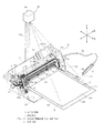
以下、本発明の第1実施形態について、図1〜図15を参照しながら説明する。図1に示すように、加工装置1は、筐体としての本体カバー2と、本体カバー2内に配設されたプラテン3(図2参照)と、カートリッジ4が搭載される加工ヘッド5と、加工対象となる対象物Sを保持するための保持シート10とを備えている。
加工装置1では、前記カートリッジ4として、カッタカートリッジ4c及びペンカートリッジ4pが複数用意されている。これらカートリッジ4c,4pは、後述する加工ヘッド5のカートリッジホルダ32に対して択一的に装着される。全てのカートリッジ4c,4pは、略同じ形状の外郭ケース50を用いて構成されており(図4参照)、説明の便宜上「カートリッジ4」として総称する。
<First Embodiment>
Hereinafter, a first embodiment of the present invention will be described with reference to FIGS. As shown in FIG. 1, a processing apparatus 1 includes a
In the processing apparatus 1, a plurality of
また、本実施形態の加工装置1は、保持シート10に保持された対象物S上の位置を指定するための超音波ペン6を備える。超音波ペン6は超音波を発信する。本体カバー2の側部には、超音波ペン6のケーブル6aが接続されるコネクタ部(図9に符号70で示す)が設けられている。本体カバー2前面の左右両側には、受信器20b,20cが設けられる。受信器20b,20cは、超音波ペン6が発信した超音波を受信する。超音波ペン6及び受信器20b,20cの詳細については後述する。
Further, the processing apparatus 1 of the present embodiment includes an
加工装置1の本体カバー2は横長な矩形箱状をなしており、その正面部には、前面開口部2aが形成されると共に、当該開口部2aを開閉する前カバー2bが設けられている。前面開口部2aが開放された状態で、対象物Sを保持した保持シート10がプラテン3上にセットされ、或いはカートリッジ4がカートリッジホルダ32に対して着脱される。
加工装置1には、プラテン3上にセットされた保持シート10を所定の移送方向(Y方向)に移送する移送機構7が設けられている。また、加工装置1には、加工ヘッド5を、保持シート10の移送方向と交差する方向(例えば移送方向と直交するX方向)に移動させるヘッド移動機構8が設けられている。以下の説明では、移送機構7による保持シート10の移送方向を前後方向とする。つまり、前後方向がY方向であり、Y方向と直交する左右方向がX方向である。
The
The processing apparatus 1 is provided with a
前記本体カバー2の上面の右側部位には、液晶カラーディスプレイ9aが設けられると共に、各種操作スイッチ9bが設けられている。液晶カラーディスプレイ9a(以下、ディスプレイ9aと称す)はフルカラー表示が可能な表示手段である。ディスプレイ9aには、種々の模様や、後述する加工条件、ユーザに対して必要なメッセージ等が表示される。また、ディスプレイ9aの表示面側には、タッチパネル9cが重ねて配設されている。前記操作スイッチ9b或いはタッチパネル9cを操作することで、ディスプレイ9aの画面における表示対象の指定、種々の模様の選択、各種のパラメータの設定等が可能である。
A liquid
図2に示すように、前記プラテン3は、対象物Sに加工を施す際、保持シート10の下面を受けるもので、前プラテン3aと後プラテン3bとからなる。このプラテン3の上面部は、水平面状をなし、対象物Sを保持した保持シート10が載置された状態で移送される。保持シート10は、例えば合成樹脂材料からなり、矩形シート状をなす。保持シート10の上面には、周縁部10a〜10dを除いた内側の領域に粘着剤が塗布された粘着層10v(図1、図14参照)が形成されている。保持シート10は、粘着層10vに貼り付けられた対象物Sを保持する保持部材である。粘着層10vの粘着力は、前記カッタやペンのカートリッジ4を用いた切断加工や印刷加工の際に対象物Sを移動不能に確実に保持し、且つ、加工後の対象物Sを比較的容易に剥がせるように設定されている。
As shown in FIG. 2, the
前記移送機構7及びヘッド移動機構8は、対象物Sを保持した保持シート10と加工ヘッド5とをX方向及びY方向に相対移動させるための相対移動手段として構成されている。
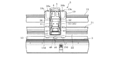
先ず、移送機構7は、プラテン3の上面側で保持シート10をY方向へ自在に移送させるものである。即ち、図1、図2に示すように、本体カバー2内には、機枠11が設けられている。その機枠11には、前記プラテン3の左右両側に夫々位置して、左右の側壁部11a、11bが向い合うように設けられている。それら左右の側壁部11a、11b間には、前プラテン3aと後プラテン3bとのなす隙間部分に位置して、X方向に夫々延びる駆動ローラ12及びピンチローラ13が設けられている。駆動ローラ12とピンチローラ13は、上下方向に並ぶように配設されており、駆動ローラ12は下側に位置し、その上側にピンチローラ13が位置する。
The
First, the
前記駆動ローラ12は、上端がプラテン3の上面と略同等の高さとなるようにして、左右の両端側が、夫々前記側壁部11a、11bに回転可能に支持されている。図2に示すように、駆動ローラ12の右端部は、右側の側壁部11bを貫通して右方に延び、その先端に径大な従動ギヤ17が固着されている。右側の側壁部11bの外面側には、取付フレーム14が固定されている。取付フレーム14には、例えばステッピングモータからなるY軸モータ15が取付けられている。Y軸モータ15の出力軸には、前記従動ギヤ17に噛合する径小な駆動ギヤ16が固定されている。
The
前記ピンチローラ13は、左右の両端部が、夫々前記側壁部11a、11bに回転可能、且つ上下方向に若干量の変位が可能に支持されている。側壁部11a、11bの外面側において、ピンチローラ13の左右の両端部の夫々を下方に付勢するバネ(図示略)が設けられている。それゆえ、ピンチローラ13は、前記バネにより、常に下方(駆動ローラ12側)に付勢されている。また、ピンチローラ13には、左右の端部寄り部位に位置して、やや径大なローラ部(右側のローラ部13aのみ図示)が設けられている。
The left and right end portions of the
こうして、保持シート10の左右の縁部10a、10bは、駆動ローラ12と、ピンチローラ13のローラ部13a、13aとの間において夫々挟持される。そして、Y軸モータ15を正転駆動、或いは逆転駆動させると、その回転運動がギヤ16,17を介して駆動ローラ12に伝わることで、保持シート10を後方或いは前方へ移送する。これら駆動ローラ12、ピンチローラ13、Y軸モータ15、減速機構としてのギヤ16,17は、移送機構7を構成する。
Thus, the left and
前記ヘッド移動機構8は、加工ヘッド5のキャリッジ19を、X方向へ自在に移動させるものである。即ち、図1、図2に示すように、左右の側壁部11a,11b間には、前記ピンチローラ13よりもやや後部寄りの上方に位置させて、上下一対のガイドレール21,22が固定されている。ガイドレール21,22は、ピンチローラ13と略平行つまり左右方向に延びている。ガイドレール21の上面部とガイドレール22の下面部には、左端から右端にわたるガイド溝(上面部のガイド溝21aのみ図示)が設けられている。
また、図示は省略するが、前記キャリッジ19の上下両側部には、両ガイド溝21a,21aを上下方向から挟むように係合する一対の突条部が設けられている。こうして、キャリッジ19は、これら突条部とガイド溝21a,21aとの係合により、ガイドレール21,22に対して左右方向への摺動が可能に支持されている。
The
Although not shown, a pair of protrusions that engage the
図1、図2に示すように、左側の側壁部11aの外面側の後部寄りには、水平状の取付フレーム24が固定されている。当該左側の取付フレーム24には、後側に位置してX軸モータ25が下向きに取付けられると共に、その前側に垂直方向に延びるプーリ軸26(図2参照)が設けられている。X軸モータ25の出力軸には、径小な駆動ギヤ27が固定されている。前記プーリ軸26には、駆動ギヤ27に噛合する径大な従動ギヤ29と、タイミングプーリ28とが回転可能に支持されている。タイミングプーリ28と従動ギヤ29は一体的に回転するように形成されている。
As shown in FIGS. 1 and 2, a
一方、右側の取付フレーム14には、タイミングプーリ30が軸方向を上下方向として回転可能に設けられている。これらタイミングプーリ30と前記タイミングプーリ28との間には、無端状のタイミングベルト31が左右方向に延びて水平に掛装されている。このタイミングベルト31の途中部が、キャリッジ19の取付部(図示略)に連結されている。
ここで、X軸モータ25を正転駆動、或いは逆転駆動させると、その回転運動がギヤ27,29及びタイミングプーリ28を介してタイミングベルト31に伝わることで、加工ヘッド5を左方或いは右方へ移動させる。こうして、キャリッジ19は、対象物Sの移送方向と直交する左右方向に自在に移動する。上記のガイドレール21,22、X軸モータ25、減速機構としてのギヤ27,29、タイミングプーリ28,30、タイミングベルト31等は、ヘッド移動機構8を構成する。
On the other hand, the timing
Here, when the
前記加工ヘッド5は、図2に示すように、キャリッジ19に対してカートリッジホルダ32と上下駆動機構33とを前後に配置してなる。上下駆動機構33は、カートリッジホルダ32をカートリッジ4ごと上下方向(Z方向)に駆動させるものである。
図2、図3、図5に示すように、キャリッジ19は、前後の壁部19a,19bと、これら壁部19a,19bを繋ぐ上下のアーム19c,19dとを備え、ガイドレール21,22の前後両側と上下両側とを囲う形状をなしている。キャリッジ19の後壁部19bには、Z軸モータ34(図2参照)が前向きに取付けられている。また、Z軸モータ34とカートリッジホルダ32との間に、当該Z軸モータ34の回転運動を減速し且つカートリッジホルダ32の上下方向の移動に変換して伝達する伝達機構(図示略)が設けられている。これら伝達機構及びZ軸モータ34は、上下駆動機構33を構成する。
As shown in FIG. 2, the
As shown in FIGS. 2, 3, and 5, the
ここで、Z軸モータ34を正転駆動、或いは逆転駆動させると、その回転運動が伝達機構を介して上下方向の運動に変換されて、カートリッジホルダ32をカートリッジ4ごと上昇位置或いは下降位置へ昇降させる。これにより、カートリッジホルダ32におけるカートリッジ4は、図4に示す刃先46での切断或いはペン先48による印刷を行うときの下降位置と、それら刃先46或いはペン先48が対象物Sから所定距離、離間する上昇位置(図3の2点鎖線参照)との間で移動する。
Here, when the Z-
尚、カートリッジホルダ32にカッタカートリッジ4cが装着されている場合、下降位置において対象物Sに刃先46が刺さった状態となる。一方、カートリッジホルダ32にペンカートリッジ4pが装着されている場合、下降位置において対象物Sにペン先48が当接した状態となる。こうした切断に係る刃先46の圧力や、印刷に係るペン先48の圧力は、後述する制御回路71によって、Z軸モータ34の回転量に基づき切断及び印刷に適した圧力に夫々設定される。
When the
図2、図3、図5に示すように、前記カートリッジホルダ32は、上下駆動機構33により上下に駆動されるホルダフレーム35と、当該ホルダフレーム35に固定された上ホルダ36及び下ホルダ37とを備えている。具体的には、キャリッジ19の前壁部19aには、その左右両側を前方から覆うカバー部材38が設けられている。カバー部材38における左側の張出部38aと右側の張出部38bとの間には、可動部として前記ホルダフレーム35が配置されている。ホルダフレーム35は、上下両面及び前面が開放されたコ字状(図2参照)をなしている。上ホルダ36及び下ホルダ37は、何れもカートリッジ4が上方から挿通されるようにして装着されるものであり、ホルダフレーム35に収まる枠状をなしている。
As shown in FIGS. 2, 3, and 5, the
図3、図5に示すように、前記ホルダフレーム35には、上ホルダ36と下ホルダ37との間に位置させてレバー部材40が設けられている。レバー部材40は、左右一対のアーム部41,42と、これらアーム部41,42の先端側を繋ぐように設けられた操作部43とを有する。レバー部材40の基端部には、アーム部41,42の外面側に位置させて枢支部(図5に右側の枢支部40aのみ図示)が夫々設けられている。これら枢支部40a,40aは、ホルダフレーム35の左右の側壁部に形成された円形穴(図5に右側の円形穴35aのみ図示)に挿通されている。また、アーム部41,42の内面側には、後述するカートリッジ4の被係合部54aと係合可能な小円柱状の係合部41a,42a(図3、図5参照)が設けられている。
As shown in FIGS. 3 and 5, the
これにより、レバー部材40は、枢支部40a,40aを揺動中心として、図5に2点鎖線で示す開放位置と、実線で示す固定位置との間で切換え可能に揺動する。同図に示すように、レバー部材40の固定位置において、係合部41a,42aとカートリッジ4の被係合部54aとの係合により、カートリッジ4は、下ホルダ37(カートリッジホルダ32)に対して固定される。他方、レバー部材40は、操作部43を手前側に引くようにして、固定位置から開放位置側へ揺動させることに伴い、係合部41a,42aが被係合部54aから離間してその固定状態を開放する。
As a result, the
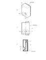
次に、上記カートリッジホルダ32に着脱されるカートリッジ4について、図4に例示するカッタとペンのカートリッジ4c,4pを説明する。
図4(a)及び(b)に示すように、カッタカートリッジ4c及びペンカートリッジ4pは、何れも同じ外郭ケース50で構成され、カートリッジホルダ32に択一的に装着される。即ち、外郭ケース50は、ケース本体51と、この本体51の一端部及び他端部に設けられたキャップ部52及び摘み部53とを備えている。ケース本体51は、上下方向に延びる円筒状をなしている。
Next, the cutter and
As shown in FIGS. 4A and 4B, the
前記キャップ部52は、ケース本体51の下端部に嵌め込まれる径大部54と径小部55とからなり、段付きの有底円筒容器状をなしている。キャップ部52の径大部54は、その上端がレバー部材40の係合部41a,42aと当接する被係合部54aであり、下端がカートリッジホルダ32の下ホルダ37と嵌合する。キャップ部52の下面部50aは平坦に形成されており、カッタ44の刃先46或いはペン先48を挿通させる孔(図示略)を有する。前記摘み部53は、ケース本体51の上端部に固定される蓋板56と、蓋板56の上側に設けられた摘み板57及び後面板58とを一体に有する。摘み板57は、蓋板56の左右方向の中央部に縦向きに設けられている。
The
図4(a)に示すカッタカートリッジ4cは切断手段(加工手段)として、外郭ケース50にカッタ軸47が収容されるカッタ44を備える。カッタ44は、基部として丸棒状をなすカッタ軸47と、先端部の刃先46とを一体に有する切断刃である。詳しい図示は省略するが、カッタ44の刃部は、対象物Sに対して傾斜した略三角形状をなしている。また、図示は省略するが、前記ケース本体51の内部には、カッタ軸47をその中心軸線50cの回りに回動可能に支持する軸受が設けられている。刃先46は、キャップ部52の下面部50aから突出している。カッタカートリッジ4cでは、カッタ軸47の中心軸線50cとキャップ部52の中心軸線とが一致するように構成されている。
The
一方、図4(b)に示すペンカートリッジ4pは、その先端のペン先48からインクを滲出させる印刷手段(加工手段)である。図示は省略するが、ケース本体51の内部には、ペン先部材49へインクを供給するためのインクタンクが設けられている。ペン先48は、キャップ部52の下面部50aから突出している。ペンカートリッジ4pでは、ペン先48の中心軸線50pとキャップ部52の中心軸線とが一致するように構成されている。
On the other hand, the
また、図4(a)、(b)に示すように、前記摘み部53の後面板58は、例えば背面側に3つの溝60A〜60Cの何れかが形成された凹凸部である。凹凸部は、カートリッジ4の種類に応じて溝60A〜60Cの有無を異ならせた凹凸パターンとなっている。即ち図4(a)及び(b)に示すように、例えば後面板58右端の溝60Cの有無により、カッタカートリッジ4cとペンカートリッジ4pとを識別することができる。また、例えばペンカートリッジ4pの溝60A,60Bの有無を異ならせて、当該カートリッジ4pの色の種類を識別することができる。尚、前記凹凸部は、色の種類に応じて当該溝の数を異ならせる等、カートリッジ4の種類の識別が可能な構成であればよい。
4A and 4B, the
図5に示すように、前記キャリッジ19には、カートリッジ4の後面板58に臨む上部側に位置させて、カートリッジ4の種類を識別するための検出ユニットが設けられている。検出ユニットは、例えば基板ホルダ61に設けられた3つの接触子62A〜62Cと、基板ホルダ61の基板に実装された3つの種類検出センサ63A〜63Cとを備える。
As shown in FIG. 5, the
3つの種類検出センサ63A〜63Cは、基板ホルダ61に、溝60A〜60Cと対応するように左右に並べて設けられた光学センサ(フォトインタラプタ)である。3つの接触子62A〜62Cは、夫々カートリッジ4の後面板58側から3つの種類検出センサ63A〜63C側にわたって延びる板状をなす。3つの接触子62A〜62Cの長手方向中間部には、軸部64が形成されている。基板ホルダ61には、板厚方向に並べた3つの接触子62A〜62Cを、夫々の軸部64にて揺動可能に支持する軸受部(図示略)が設けられている。また、3つの接触子62A〜62Cの上寄りの部位と基板ホルダ61との間には、夫々引張りコイルバネ(図示略)が掛け渡されるように設けられている。これら引張りコイルバネによって、3つの接触子62A〜62Cは、上端部が3つの種類検出センサ63A〜63C側へ傾く方向、つまり下端部が摘み部53の後面板58に接触する方向へ付勢されている。
The three types of
例えば、カッタカートリッジ4cがカートリッジホルダ32に装着された時、接触子62A,62Bは、下端部が後面板58に接触して揺動することに伴い、上端部が種類検出センサ63A,63Bから離間する(図5の2点鎖線参照)。一方、他の接触子62Cは、下端部が後面板58の溝60C側へ、上端部が種類検出センサ63C側へ収まるように傾いた姿勢が維持される。
対象物Sの切断に際し、制御回路71は、種類検出センサ63A〜63Cによる接触子62A〜62Cの検出信号に基づき、カートリッジホルダ32に装着されたカッタカートリッジ4cを、上下駆動機構33により下降位置に移動させ、前述したカッタ圧に設定する。この場合、刃先46が保持シート10上の対象物Sを貫通して、保持シート10に僅かに刺さっている状態となる。この状態で、前記移送機構7及びヘッド移動機構8により、保持シート10とカッタカートリッジ4cとをX方向及びY方向に相対移動させることで、対象物Sに対する切断動作が実行される。
For example, when the
When cutting the object S, the
一方、カートリッジホルダ32にペンカートリッジ4pが装着されている場合、制御回路71は、接触子62A〜62Cの検出信号に基づき、ペンカートリッジ4pの下降位置でペン先48を対象物Sに当接させて前記ペン圧に設定する。この状態で、移送機構7及びヘッド移動機構8により、保持シート10とペンカートリッジ4pとをX方向及びY方向に相対移動させることで、対象物Sに対する印刷動作が実行される。
尚、前記キャリッジ19の下面部には、プラテン3上にセットされた保持シート10(当該シート10のY方向位置)を検出するためのシート検出センサ66(図9参照)が設けられており、その検出信号が制御回路71に入力される。加工装置1では、例えば図1に示す保持シート10における粘着層10vの左角部を原点OとしたXY座標系が設定され、その2次元座標系に基づいて上記した保持シート10(対象物S)と加工ヘッド5(カートリッジ4)との相対移動が行われる。
On the other hand, when the
A sheet detection sensor 66 (see FIG. 9) for detecting the holding sheet 10 (the Y-direction position of the sheet 10) set on the
さて、本実施形態の加工装置1では、図1に示すプロジェクタ67によって、前記切断動作や印刷動作を行う対象物S上の加工位置が、対象物S上に表される。また、加工装置1では、前記超音波ペン6によって予め対象物S上の任意の位置を指定し、その指定位置を、受信器20b,20cで検出して前記加工位置として設定することができる。これら、超音波ペン6、受信器20b,20c及びプロジェクタ67について、図6〜図9も参照しながら詳述する。
超音波ペン6は、ケーブル6aの一端部が接続されている。ケーブル6aの他端部は、コネクタ部70に接続される。このように、超音波ペン6は、コネクタ部70に接続ケーブル6aを介して接続されることで(図9参照)、加工装置1側から電力が供給される一方、加工装置1側へ電気信号を出力する。
Now, in the processing apparatus 1 of this embodiment, the processing position on the target object S which performs the said cutting operation | movement and printing operation is represented on the target object S by the
The
図6に示すように、超音波ペン6は、ペン本体72とペン先73aを備える。ペン本体72は棒状をなしている。ペン本体72の先端側(同図で下端側)には、先端程細くなる尖った形状のペン先73aが配設されている。ペン先73aは、ペン本体72に対して長手方向へ押し込み可能に突設されている。ペン先73aを対象物Sに当接させて、ペン本体72内に押し込む操作を行うことができる。図示は省略するが、ペン本体72内には、ペン先73aをペン本体72から突出させる方向へ付勢する付勢部材が設けられている。ペン先73aは、押し込まれる力が解除されると、付勢部材の付勢力により、ペン本体72から突出した元の突出位置に戻る。また、ペン本体72におけるペン先73a寄りの部分には、ボタン73bが設けられている。ユーザは、超音波ペン6を手で持ちながら、指先で、ボタン73bを押す操作を行うことができる。
As shown in FIG. 6, the
図9に示すように、超音波ペン6は、ペン本体72の内部に、超音波発信器75、信号出力回路74及びスイッチ73を備える。超音波発信器75は、ペン先73aに近接して配置されており、その駆動時にペン本体72の先端側から超音波を発信するように構成されている。信号出力回路74は、前記ケーブル6aを介して加工装置1に信号を伝送する。スイッチ73は、前記ペン先73aの位置或いはボタン73bの操作に応じて、信号出力回路74と超音波発信器75との出力状態を切り替える。
As shown in FIG. 9, the
即ち、超音波ペン6を使用しない場合、ペン先73aは突出位置にあり、スイッチ73はOFF状態にある。スイッチ73のOFF状態では、超音波発信器75は超音波を発信せず、信号出力回路74は電気信号を出力しない。しかし、ユーザが対象物S上の任意の位置にペン先73aを押し当てると、ペン先73aはペン本体72に入り込み、スイッチ73がON状態に切り替わる。或いは、ユーザは、ペン先73aを押し当てる代わりに、対象物S上の任意の位置にペン先73aを配置した状態でボタン73bを押す操作を行うと、ボタン73b操作に応動してスイッチ73がON状態に切り替わる。スイッチ73がON状態になると、超音波発信器75は超音波を発信すると同時に、信号出力回路74はケーブル6aを介して加工装置1に信号を伝送する。
That is, when the
また、前記超音波発信器75はペン先73a側に近接配置されているため、ペン先73aの位置を超音波の発信源と見做すことができる。また、上記のケーブル6aは、信号出力回路74からの信号を伝送するだけでなく、超音波ペン6に電源を供給する。このため、超音波ペン6は、電池を内蔵する必要がなく、軽量化を図ることができる。尚、超音波ペン6は、ボタン73bが無い構成であってもよい。又は、超音波ペン6は、ペン先73aがペン本体72と一体的に形成されており、ボタン73bだけがある構成であってもよい。
Further, since the
前記受信器20b,20cは、超音波ペン6から発信された超音波を検出(受信)する検出手段である。図1に示す本体カバー2における左右一対の受信器20b,20cは夫々同じ構成であり、一方の受信器20bについて図8(a)〜(c)も参照しながら説明する。
受信器20bの外郭をなすケース77は、上下方向にやや長い中空の直方体形状をなしている。ケース77の前面下部には、中央に位置して開口部78が設けられている。開口部78の形状は、図8(b)に示す正面視にて左右方向に長い楕円形状をなしている。開口部78の周囲には、後方から前方へ向かうに従い、すり鉢状に拡開するテーパ面78a(傾斜面)が形成されている。図8(c)に示すように、受信器20bのケース77には、基板79が収容されている。基板79の前側には開口部78に臨む位置にマイク80が実装され、基板79の後側上部には、コネクタ部81が実装されている。
The
A
上記の受信器20bは、図1に示す本体カバー2の左端部に、開口部78を前に向けて(コネクタ部81を後方に向けて)配置される。コネクタ部81は、前記制御回路71に接続される。他方、本体カバー2の右端部には、受信器20cが、受信器20bと同様に配置され、受信器20cのコネクタ部81も制御回路71に接続される。これら受信器20b,20cは、マイク80(開口部78)が対象物Sより若干上方に位置するように設置される。こうして、受信器20b,20cは、超音波ペン6から発信される超音波を本体カバー2の前側で受信する。なお、受信器20b,20cを設ける位置は、超音波ペン6から発信される超音波を受信可能な位置であればよいので、上記位置に限定されることなく、適宜変更が可能である。
The
また、制御回路71は位置特定手段として、受信器20b,20cによる超音波の検出信号と、ケーブル6aを介した超音波ペン6からの伝送信号とに基づき、対象物S上の前記指定位置を特定する。指定位置は、空間全体を表すワールド座標系で特定され、加工装置1における前述したX方向とY方向の座標系で表わすことができる。ここで、本実施形態のワールド座標系は3次元座標系であって、前述した加工装置1の2次元座標系と同じく保持シート10の粘着層10vの左角部を原点Oとする。
Further, the
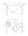
前記プロジェクタ67は、前記指定位置を表す画像を、対象物S上に投影する投影手段である。図1、図7に示すように、プロジェクタ67は、例えば矩形箱状をなす筺体85に収容されている。
筺体85は、図1に示すように、本体カバー2後部に立設された上下方向に延びる支持部材84によって、加工装置1の上方に配置される。支持部材84は、筺体85を対象物Sから所定距離離間させ、且つ保持シート10中心部に向けて投影中心光軸が斜め前下方を指向するように筺体85を支持する。図示は省略するが、プロジェクタ67は、投影する画像のサイズ及び焦点を調整するための調整手段を備える。これにより、プロジェクタ67は、対象物S(保持シート10の粘着層10v)の領域に合わせた所定の投影範囲Q(図1参照)に画像を投影する。
The
As shown in FIG. 1, the
具体的には、図7に示すように、プロジェクタ67は、筺体85内に、光源86、液晶パネル87、及び結像レンズ88を備えている。光源86、例えばメタルハライドランプ等の放電ランプで構成されている。液晶パネル87は、光源86から入射した光を変調し、別途入力される画像データに基づき、投影する画像光を形成する。結像レンズ88は、液晶パネル87で形成された画像光を、筺体85下部の投光用開口部89を通して、対象物S上の投影範囲Qに結像させる。これにより、対象物S上に、画像データに基づく画像が投影される(図13(b)の標識100参照)。
この場合、プロジェクタ67において、対象物Sに対し斜め上方から画像を投影するため、その画像の歪みを補正する処理が行われる。そして、標識100に係る前記画像データは、加工装置1の座標系と関連付けられており、前述した指定位置に基づいて当該画像データの座標位置を修正することができる。尚、プロジェクタ67から投影する画像は、複数色のカラー画像であるが、単色の画像であってもよいし、対象物Sの色に応じた色に調整してもよい。
Specifically, as shown in FIG. 7, the
In this case, the
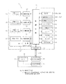
次に、加工装置1の制御系の構成について、図9を参照しながら説明する。加工装置1全体の制御を司る制御回路(制御手段)71は、コンピュータ(CPU)を主体に構成されており、ROM92、RAM93、EEPROM94が接続されている。
ROM92には、切断動作を制御するための切断制御プログラムや、印刷動作を制御するための印刷制御プログラムが記憶されている。また、ROM92には、後述するメイン処理を実行するための処理プログラムや、ディスプレイ9aの表示を制御する表示制御プログラム等が記憶されている。EEPROM94には、複数種類の模様を切断するための切断データや、複数種類の模様を印刷するための印刷データ、投影画像たる標識の画像データを生成するための各種パラメータ等が記憶されている。
Next, the configuration of the control system of the machining apparatus 1 will be described with reference to FIG. A control circuit (control means) 71 that controls the entire processing apparatus 1 is mainly composed of a computer (CPU), and is connected to a
The
制御回路71には、前記シート検出センサ66、種類検出センサ63A〜63C、受信器20b,20c等の信号が入力される。受信器20b,20cの信号は、前記基板79に実装されたマイク80の増幅回路(図示しない駆動回路)により増幅される。制御回路71には、ディスプレイ9a及びタッチパネル9cが接続されると共に、各種操作スイッチ9bが接続されている。ユーザは、ディスプレイ9aの表示を見ながら、各種操作スイッチ9bやタッチパネル9cを操作することにより、所望する模様を選択したり、各種のパラメータを設定することができる。また、制御回路71には、プロジェクタ67の光源86が接続されると共に、液晶パネル87、Y軸モータ15、X軸モータ25、Z軸モータ34を夫々駆動する駆動回路96,97,98,99が接続されている。制御回路71は、切断データ或いは印刷データに基づいて、Y軸モータ15、X軸モータ25、Z軸モータ34等を制御し、保持シート10上の対象物Sに対する切断動作或いは印刷動作を自動で実行させる。
Signals from the
一方、超音波ペン6において、スイッチ73は信号出力回路74及び超音波発信器75と電気的に夫々接続されている。このうち、信号出力回路74は、ケーブル6a及びコネクタ部70を介して制御回路71に接続されている。従って、スイッチ73がON状態になると、信号出力回路74によるケーブル6aを介した制御回路71側への信号の伝送と、超音波発信器75による超音波の発信とが同時に行われる。
On the other hand, in the
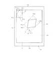
続いて、超音波ペン6により指定された対象物S上の指定位置の特定方法について、図1、図13(a)も参照しながら説明する。ここで、対象物Sは、保持シート10に保持された状態で加工装置1にセットされ、図1に示すように保持シート10の後側隅部がピンチローラ13のローラ部13a,13aと駆動ローラ12との間に挟持される。これにより、対象物Sを保持した保持シート10は、プラテン3上面の前方側の所定位置に、略水平となるように位置決めされる。この保持シート10上の対象物Sに対して、ユーザが超音波ペン6のペン先73aを押し当てるか、或いはボタン73bの操作により、任意の位置を指定する。以下、説明を簡単にするため、ユーザは、ペン先73aを押し当てることで、任意の位置を指定するものとする。
Next, a method for specifying the designated position on the object S designated by the
このとき、指定する指定位置は、対象物Sの位置する粘着層10vの領域、つまりプロジェクタ67の投影範囲Q内にあるものとする。また、以下に述べるように、ペン先73aを押し当てた時における、超音波の発信源たる超音波発信器75の位置を指定位置として特定する。つまり、ペン先73aと超音波発信器75とは非常に近接して配置されている。このため、ペン先73aが押し当てられた対象物S上の位置を指定位置と見做すことができる。
At this time, the designated position to be designated is assumed to be within the area of the
また、指定位置は、前記ワールド座標系の3次元の座標情報(X座標、Y座標、Z座標)で特定される。ワールド座標系の原点(0,0,0)は、保持シート10の粘着層10vの左角部であり、Z座標は、保持シート10の上面で0となる。ここで、指定位置の座標を、図13(a)に示すようにE(Xe,Ye,Ze)とする。また、左側の受信器20bにおけるマイク80の位置の座標をB(Xb,Yb,Zb)とし、右側の受信器20cにおけるマイク80の位置の座標をC(Xc,Yc,Zc)とする。これら受信器20b,20cの各座標B,Cの値Xb〜Zb,Xc〜Zcは、ROM92に予め記憶されている。尚、受信器20b,20cのZ座標であるZb,Zcは、保持シート10の上面に対する各マイク80の高さを表す。
The designated position is specified by three-dimensional coordinate information (X coordinate, Y coordinate, Z coordinate) of the world coordinate system. The origin (0, 0, 0) of the world coordinate system is the left corner of the
以下、座標Eを「指定座標E」、指定座標Eと座標Bとの問の距離を「距離EB」、指定座標Eと座標Cとの間の距離を「距離EC」とする。この場合、図13(a)の平面図に示す距離EB,ECは、三平方の定理に基づき、座標B,C,Eの値で表すことができる。具体的には、距離EBは、座標E,Bの値を用いた次式(1)、距離ECは、座標E,Cの値を用いた次式(2)で表される。
(Xb−Xe)2+(Yb−Ye)2+(Zb−Ze)2=(EB)2 … (1)
(Xc−Xe)2+(Yc−Ye)2+(Zc−Ze)2=(EC)2 … (2)
式(1)は、中心点を座標B、半径を距離EBとして、指定座標Eを通る球面の方程式と同一である。同様に式(2)は、中心点を座標C、半径を距離ECとして、指定座標Eを通る球面の方程式と同一である。
Hereinafter, the coordinate E is “designated coordinate E”, the distance between the designated coordinate E and the coordinate B is “distance EB”, and the distance between the designated coordinate E and the coordinate C is “distance EC”. In this case, the distances EB and EC shown in the plan view of FIG. 13A can be expressed by the values of the coordinates B, C, and E based on the three-square theorem. Specifically, the distance EB is expressed by the following equation (1) using the values of the coordinates E and B, and the distance EC is expressed by the following equation (2) using the values of the coordinates E and C.
(Xb-Xe) 2 + (Yb-Ye) 2 + (Zb-Ze) 2 = (EB) 2 (1)
(Xc-Xe) 2 + (Yc-Ye) 2 + (Zc-Ze) 2 = (EC) 2 (2)
Expression (1) is the same as the equation of the spherical surface passing through the designated coordinates E, where the center point is the coordinate B and the radius is the distance EB. Similarly, the equation (2) is the same as the equation of the spherical surface passing through the designated coordinate E, where the center point is the coordinate C and the radius is the distance EC.
また、指定座標Eを指定した超音波ペン6から超音波が発信されてから、左側の受信器20bにおいて当該超音波を検出するまでに要する時間を伝達時間Tb、右側の受信器20cにおいて当該超音波を検出するまでに要する時間を伝達時間Tcとする。この場合、距離EB,ECは、超音波の速度(測定空間中の音速)をVとして、次の式(3)、式(4)で表すことができる。
EB=V×Tb … (3)
EC=V×Tc … (4)
Further, the time required for detecting the ultrasonic wave in the
EB = V × Tb (3)
EC = V × Tc (4)
上記式(1)に式(3)を代入して次式(5)が得られ、式(2)に式(4)を代入して次式(6)が得られる。
(Xb−Xe)2+(Yb−Ye)2+(Zb−Ze)2=(V×Tb)2 … (5)
(Xc−Xe)2+(Yc−Ye)2+(Zc−Ze)2=(V×Tc)2 … (6)
Substituting equation (3) into equation (1) above gives equation (5), and substituting equation (4) into equation (2) yields equation (6) below.
(Xb-Xe) 2 + (Yb-Ye) 2 + (Zb-Ze) 2 = (V × Tb) 2 (5)
(Xc−Xe) 2 + (Yc−Ye) 2 + (Zc−Ze) 2 = (V × Tc) 2 (6)
式(5)及び式(6)における、座標BのXb,Yb,Zbの値、座標CのXc,Yc,Zcの値、及び音速Vの値は既知であり、ROM92に記憶されている。伝達時間Tb,Tcは、超音波ペン6の超音波発信器75から超音波が発信されたタイミングと、各受信器20b,20cで超音波が検出されたタイミングとの差から算出する。以下では、超音波発信器75から超音波を発信したタイミングを「発信タイミングT1」といい、左側の受信器20b及び右側の受信器20cで超音波を夫々検出したタイミングを「検出タイミングT2b」及び「検出タイミングT2c」という。
また、加工装置1では、対象物Sは保持シート10に保持された状態でプラテン3上にセットされており、対象物Sの厚みは無視できる程度に薄いので、対象物Sの上面のZ座標を0(Ze=0)としてよい。こうして、上記した各タイミングT1,T2b,T2cを計測して得た伝達時間Tb,Tcと既知の値Xb〜Zb,Xc〜Zc,Vとに基づいて、式(5)と式(6)の連立方程式を解くことにより、指定座標E(Xe、Ye、Ze(=0))を算出する。このとき、受信器20b,20cの指向性(マイク80の指向性)が考慮され、座標Eが特定される。
In Expressions (5) and (6), the values of Xb, Yb, and Zb at coordinates B, the values of Xc, Yc, and Zc at coordinates C, and the value of sound velocity V are known and stored in the
Further, in the processing apparatus 1, the object S is set on the
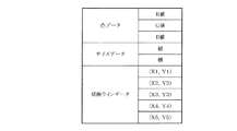
ここで、前記切断データについて、保持シート10に保持された対象物Sに図11に示す模様Aの切断加工を施す場合を例に説明する。即ち、対象物Sから菱形の模様Aをカッタ44で切り抜くものとする。この場合の切断データは、図10に示す色データ、サイズデータ、及び切断ラインデータと、表示用のデータとを含む。例えば、RGB値で表わされる色データは、表示用のデータと関連付けられている。従って、模様Aの表示用のデータに基づいて、ディスプレイ9aに表示する画像や、プロジェクタ67から投影する標識の画像を、カラー画像で表すことができる。また、サイズデータは、模様Aの縦横の大きさを表す値で、模様Aの形状に対応する切断領域を表す。例えば、図11に示す菱形の模様Aの切断領域は、その頂点A0〜A3に接して模様Aを囲う矩形枠Wの大きさで表わされる。切断ラインデータは、複数の線分からなる切断ラインの頂点を夫々XY座標によって示した座標値のデータであって、加工装置1のXY座標系で規定されている。
Here, the case where the cutting process of the pattern A shown in FIG. 11 is performed on the object S held on the holding
具体的には、図11に示すように模様Aの切断ラインは、4つの線分L1〜L4からなり、切断開始点A0と切断終了点A4が一致する閉じた四角形である。切断ラインデータは、切断開始点A0、頂点A1、頂点A2、頂点A3、切断終了点A4の夫々に対応する第1座標値(X1、Y1)、第2座標値(X2、Y2)、第3座標値(X3、Y3)、第4座標値(X4、Y4)、第5座標値(X5、Y5)のデータを有する。これら座標値は、例えば図11に示す矩形枠Wの左上の点W14を座標原点とし、その座標原点が保持シート10の原点Oに対応するものとして前記切断ラインデータに基づき切断が行われる(図14参照)。 Specifically, the cutting line of the pattern A as shown in FIG. 11, consists of four line segments L1 to L4, is a rectangle closed to the cutting start point A 0 cutting end point A 4 are identical. The cutting line data includes a first coordinate value (X1, Y1) and a second coordinate value (X2, X2) corresponding to the cutting start point A 0 , the vertex A 1 , the vertex A 2 , the vertex A 3 , and the cutting end point A 4 . Y2), third coordinate values (X3, Y3), fourth coordinate values (X4, Y4), and fifth coordinate values (X5, Y5). These coordinate values are cut based on the cutting line data assuming that the upper left point W14 of the rectangular frame W shown in FIG. 11 is the coordinate origin and that the coordinate origin corresponds to the origin O of the holding sheet 10 (FIG. 11). 14).
即ち、加工装置1では、模様Aを切断する場合、前記移送機構7及びヘッド移動機構8により、切断開始点A0のXY座標へカッタ44を相対的に移動させる。次いで、上下駆動機構33によりカッタ44の刃先46を対象物Sの切断開始点A0に貫通させ、移送機構7及びヘッド移動機構8により、当該刃先46を、頂点A1、頂点A2、頂点A3、切断終了点A4を順次直線で繋ぐようにして相対的に移動させる。こうして、線分L1、L2、L3、L4について、順次連続して切断が行われることで、模様Aの輪郭つまり菱形が切り抜かれる。
That is, in the processing apparatus 1, when cutting the pattern A, the
前記印刷データについて、対象物Sに対し上記した模様Aの印刷加工を施す場合を例に説明する。図示は省略するが、印刷データは、印刷ラインデータと、色データと、サイズデータと、表示用のデータとを含む。
具体的には、図11に示すように、対象物Sに模様Aをペンカートリッジ4pで印刷して、前記線分L1〜L4からなる菱形を描くものとする。模様Aの印刷ラインデータは、夫々の線分L1〜L4に対応する線分データからなる。各線分データは、例えば前記切断ラインデータと同様に、対応する線分L1〜L4の始点及び終点が夫々XY座標によって示される座標値のデータを有する。前記色データは、ペンカートリッジ4pの色の種類を表し、表示用のデータと関連付けて予め設定されている。前記サイズデータは、前述した切断領域の矩形枠Wと同様に、印刷領域の大きさを、模様Aが内接する最小の矩形枠Wで表される。
The case where the printing process of the above-mentioned pattern A is performed with respect to the object S about the said print data is demonstrated to an example. Although illustration is omitted, the print data includes print line data, color data, size data, and display data.
Specifically, as shown in FIG. 11, the pattern A is printed on the object S with the
印刷の際、色データに基づいて、該当する種類のペンカートリッジ4pがディスプレイ9aに表示される。ユーザは、ディスプレイ9aの表示を見て、当該カートリッジ4pをカートリッジホルダ32に装着する。そして、制御回路71は、前述した印刷動作の実行により、印刷ラインデータに基づきペンカートリッジ4pを相対的に移動させ、対象物Sに前記線分L1〜L4を作図することで、模様Aを色データの色で印刷する。
前記EEPROM94には、上記した模様Aを含む種々の模様の切断データや印刷データが記憶されている。以下では、切断データと印刷データを総称して加工データといい、前記切断動作と印刷動作を総称して、加工動作という。
At the time of printing, the corresponding type of
The
上記のように、加工データは、加工装置1のXY座標系で規定される座標値のデータを含み、座標値のデータは、前記ワールド座標系と予め関連付けて設定されている。そこで、本実施形態では、選択した模様の加工データについて、ワールド座標系で表される指定座標に基づき、超音波ペン6を用いた加工条件の設定変更が可能とされている。ここで、図12は、加工条件の設定の際、ディスプレイ9aに表示される加工条件設定画面108を示している。加工条件設定画面108には、模様の加工条件を設定するための図形110と、OKキー109が設けられている。
As described above, the machining data includes coordinate value data defined in the XY coordinate system of the machining apparatus 1, and the coordinate value data is set in advance in association with the world coordinate system. Therefore, in the present embodiment, it is possible to change the setting of the processing conditions using the
前記図形110は、加工条件として例えば模様の加工位置、模様の角度及び大きさを設定するため、図12に示すように複数の図形要素(図形群)で構成されている。即ち、図形群110は、4つの点ブロック111〜114、8つの辺ブロック121〜128、矢印ブロック129、及び中心点ブロック130を含む。図形群110の4隅の点ブロック111〜114は、模様の矩形枠Wの各頂点に対応する図形であり、辺ブロック121〜128は、その頂点間の辺に対応する図形である。矢印ブロック129は、模様の角度を表すための図形である。また、中心点ブロック130は、加工領域である矩形枠Wの中心点に対応する図形である。図形群110が表示されている場合、その画面108における横方向及び縦方向は、上記したX方向及びY方向に対応する。
The graphic 110 is composed of a plurality of graphic elements (graphic groups) as shown in FIG. 12 in order to set, for example, a pattern processing position, a pattern angle, and a size as processing conditions. That is, the
前記超音波ペン6を使用する際、予めタッチパネル9c上で、図形群110の何れかのブロック111〜114,121〜130を、手指又は図示しない専用のタッチペンでタッチする(以後、タッチ操作と称す)ことにより選択する。例えば辺ブロック121を選択した場合、図12に示すように、当該辺ブロック121が白抜き表示から黒色での塗潰し表示に変更される。このように、ブロック111〜114,121〜130を選択することで、超音波ペン6で入力する加工条件の種類が模様の加工位置、角度及び大きさの何れであるか、或いは加工条件を設定する基準となる部位を、予め制御回路71に認識させる。
When the
具体的には、模様Aの加工位置の設定変更を行う場合、図形群110のうち中心点ブロック130を含む点ブロック111〜114,130の中から1つの点ブロックを選択する。これにより、制御回路71は、後に超音波ペン6で入力される指定座標を、模様Aの加工位置を指定する情報として処理する。従って例えば、図12で左上の点ブロック114を選択した後、超音波ペン6で対象物S上の任意の位置を指定したとする。この場合、模様Aの加工位置は、矩形枠Wの点W14が保持シート10の原点Oに合致する初期の位置(図14で左上の隅)から、点W14を指定位置に合わせた位置に変更される。
Specifically, when changing the setting of the processing position of the pattern A, one point block is selected from the point blocks 111 to 114 and 130 including the
模様Aの角度の設定変更を行う場合、図形群110のうち辺ブロック121〜128及び矢印ブロック129の中から1つを基準として選択する。これにより、制御回路71は、後に超音波ペン6で入力される2つの指定座標を、模様Aの角度を設定するための第1指定位置及び第2指定位置の情報として処理する。例えば、図12に示すように辺ブロック121を選択した後、超音波ペン6で対象物S上の2箇所(図13(b)の符号201,202参照)を指定したとする。この場合、模様Aは、辺ブロック121に対応する矩形枠Wの辺W21(図11参照)と、第1指定位置201及び第2指定位置202を通る仮想線分とのなす角度を回転角度として向きが変更される。
When changing the setting of the angle of the pattern A, one of the side blocks 121 to 128 and the
尚、前記仮想線分は、図13(b)において第1指定位置201から第2指定位置202に向かうベクトルの矢印で表わしている。また、模様Aの角度を変更するために、上記の辺ブロック121〜128を選択せずに矢印ブロック129を選択したとする。この場合、詳しい図示は省略するが、超音波ペン6で第1指定位置201及び第2指定位置202を指定すれば、当該ブロック129の矢印が、第1指定位置201から第2指定位置202に向かうベクトルの矢印と合致するように、模様Aの角度を変更することができる。
The virtual line segment is represented by a vector arrow from the first designated
模様Aの大きさの設定変更を行う場合、図形群110のうち点ブロック111〜114,130の中から2つの点ブロックを基準として選択する。これにより、制御回路71は、後に超音波ペン6で入力される2つの指定座標を、模様の大きさを画する一対の指定位置を指定する情報として処理する。例えば、対角にある2つの点ブロック111,113を選択した後、超音波ペン6で図13(b)の第1指定位置201と第2指定位置203を指定したとする。この場合、模様Aは、2つの点ブロック111,113に対応する矩形枠Wの点W11,W13を、両指定位置201,203に合致させるように拡大する。
また、本実施形態の加工装置1では、投影される標識によって模様Aの加工位置、角度及び大きさを視認することができる。制御回路71は、上記した加工条件の設定変更が行われると、その変更内容を投影中の標識100に反映させる(図13(b)の標識101〜103参照)。
When changing the setting of the size of the pattern A, two point blocks are selected from the point blocks 111 to 114 and 130 in the
Moreover, in the processing apparatus 1 of this embodiment, the processing position, angle, and size of the pattern A can be visually recognized by the projected sign. When the setting change of the processing conditions described above is performed, the
次に、上記構成の作用について、メイン処理を説明する。メイン処理は、ユーザが選択した模様について、加工条件を必要に応じて前記指定座標に基づき設定変更し、変更後の加工条件で加工動作を実行させる処理である。図15のフローチャートは、制御回路71が実行させるメイン処理の一連の流れを示している。
先ずユーザは、加工の対象物Sとなる例えば紙を保持シート10に貼り付け、その保持シート10を加工装置1のプラテン3上にセットする。これにより、保持シート10の後側隅部がピンチローラ13のローラ部13a,13aと駆動ローラ12との間に挟持されることで、保持シート10上の対象物Sが、プラテン3上面の前方側の所定位置に、略水平となるように位置決めされる。
Next, the main process will be described with respect to the operation of the above configuration. The main process is a process of changing the machining condition for the pattern selected by the user based on the designated coordinates as necessary and executing the machining operation under the changed machining condition. The flowchart in FIG. 15 shows a series of main processes executed by the
First, the user attaches, for example, paper as the processing object S to the holding
また、ユーザは、ディスプレイ9aに模様選択画面(図示略)を表示させ、所望する模様をタッチ操作により選択する(ステップS1)。これにより、制御回路71は、選択された模様の加工データをEEPROM94から読出してRAM93に展開し、ディスプレイ9aに、加工条件設定画面108を表示させる(ステップS3)。
そして、制御回路71は、選択された模様の加工データに基づき、その加工条件を表す標識100を投影するための画像データを生成する。例えば、模様Aの初期の加工条件は、加工データに含まれる前記サイズデータ及び座標値のデータで定められ、係る矩形枠Wの座標原点W14が保持シート10の原点Oに一致する(図14参照)。従って、模様Aの加工データに基づいて、その加工条件を表す標識100の画像データが生成され、プロジェクタ67によって当該画像データに基づく標識100の画像が対象物S上に投影される(ステップS5)。
The user displays a pattern selection screen (not shown) on the
Then, the
標識100は、例えば図13(b)に示すように、前記図形群110を模した形状をなしている。即ち、標識100の外枠100aは、加工領域である矩形枠Wを表し、外枠100a内部の図形は、十字図形100bと矢印図形100cを組み合わせてなる。標識100において、十字図形100bの交点100dである中心点は、模様Aの加工領域の中心点を表す。また、標識100の矢印図形100cの向きは、初期の模様Aの向きを表し、模様Aの角度を変更しない場合のY軸プラス方向(対象物Sが後方へ移動する方向)と一致する。尚、標識は、模様の加工条件を視認できるものであればよく、前記加工データの表示用のデータに基づいて、プロジェクタ67で切断ライン或いは印刷ラインを表す画像を標識として投影してもよい。
The
こうして、前記ステップS5では、ユーザは対象物S上の標識100を視認でき、加工条件の設定を確認することができる。標識100で表わされる初期の加工条件で模様Aの加工を施す場合、ユーザは、加工条件設定画面108のOKキー109をタッチ操作する(ステップS7,S13,S19でNO且つステップS27にてYES)。これにより、対象物Sに対して、初期の加工条件で、模様Aの切断加工或いは印刷加工を施すことができる(ステップS31)。尚、切断加工及び印刷加工の手順については、後に詳述する。
Thus, in step S5, the user can visually recognize the
一方、ユーザは、加工条件設定画面108の図形群110をタッチ操作して、初期の加工条件の設定を変更することができる。例えば、図形群110のうち1つの点ブロック111をタッチ操作した場合、制御回路71は、変更する加工条件が加工位置であると判断し、以後、超音波ペン6により入力される指定座標を模様Aの加工位置を指定する情報として処理する(ステップS7にてYES)。
On the other hand, the user can touch the
これにより、ユーザは超音波ペン6を用いて、対象物S上における任意の位置にペン先73aを押し当てる操作により加工位置を指定することができる。このとき、超音波ペン6の信号出力回路74は、ペン先73aを押し当てたタイミングで、ケーブル6aを介して電気信号を出力する。同時に、超音波発信器75は超音波を発信する。制御回路71は、ケーブル6aを介して信号出力回路74から電気信号を検出した時、その検出した時刻を発信タイミングT1として取得する。また、制御回路71は、左右の受信器20b,20cで超音波を検出した時、各受信器20b,20cでの検出時刻を検出タイミングT2b,T2cとして夫々取得する。こうして、指定位置を表す情報として、発信タイミングT1と検出タイミングT2b,T2cが取得される(ステップS8)。
As a result, the user can use the
また、制御回路71は、各タイミングT1,T2b,T2cから各受信器20b,20cでの伝達時間Tb,Tcを算出する。そして、算出した伝達時間Tb,Tcと前述した既知の値Xb〜Zb,Xc〜Zc,Vとに基づいて式(5)と式(6)との連立方程式を解く演算を行い、受信器20b,20cの指向性から、1つの指定位置の座標を特定する(ステップS9)。このとき、例えば図13(b)に示す指定位置201の座標が特定されたものとする。
Further, the
この場合、制御回路71は、模様Aの加工データについて、点ブロック111に対応する矩形枠Wの点W11を指定位置201に合わせた座標値に変換する(図13(b)の外枠101a参照)。こうして、模様Aの新たな加工位置が設定されると(ステップS11)、その変更後の加工位置を、投影中の標識100に反映する処理が実行される(ステップS25)。この処理により、標識100の画像データは、点ブロック111に対応する外枠101aの角部を指定位置201に合わせた標識101の画像データに変換される。上記した加工データの座標変換や画像データの座標変換は、矩形枠Wの点W11と指定位置201との間におけるX方向の差分及びY方向の差分を移動量として平行移動するもので、周知の変換手法を適用することができる。これにより、超音波ペン6で設定された変更後の加工位置は、対象物S上に投影中の標識100にすぐにフィードバックされ、変更後の標識101が投影される。このため、変更した加工位置について、対象物S上の標識101により直接且つ正確に把握することができる。
In this case, the
続いて、ユーザは、加工条件設定画面108において、OKキー109をタッチ操作せずに(ステップS27にてNO)、図形群110の辺ブロック121をタッチ操作したとする。この場合、制御回路71は、変更する加工条件が模様Aの角度であると判断し(ステップS7にてNO、ステップS13にてYES)、以後、超音波ペン6により入力される2つの指定座標を、模様Aの角度を設定するための第1指定位置及び第2指定位置の情報として処理する。
ここで、ユーザは、上記した超音波ペン6の操作により、図13(b)に示す対象物S上の2箇所201,202を順に指定したとする(ステップS14)。この場合、模様Aは、その矩形枠Wの各辺が保持シート10の周辺と平行をなす初期の向きから(図13(b)の外枠101a参照)、次のように角度が変更される。即ち、制御回路71は、2つの指定位置について前記ステップS9と同様の演算を行い、第1指定位置201と第2指定位置202の座標を特定する(ステップS15)。次いで、特定した両指定位置201,202を通る仮想線分と、前記辺ブロック121に対応する矩形枠Wの辺W21(図11参照)とのなす角度を算出する(ステップS17)。
Subsequently, it is assumed that the user touches the side block 121 of the
Here, it is assumed that the user sequentially designates two
そして、制御回路71は、模様Aの加工データについて、算出した角度の分、指定位置201を中心に模様Aを回転させた座標値に変換する。これにより、模様Aの加工領域を、第1指定位置201から第2指定位置202に向かうベクトルと、矩形枠Wの点W11から点W12に向かうベクトルとが一致するように回転させる(図13(b)の外枠102a参照)。また、制御回路71は、前記ステップS17で算出した角度を、投影中の標識101に反映する処理を実行する(ステップS25)。この処理により、標識101の画像データは、変更後の模様Aの角度に合わせた標識102の画像データに変換される。こうして、対象物S上において、変更後の模様Aの角度を反映した標識102が投影され、その標識102により、傾けた模様Aの加工領域を識別することができる。
Then, the
更に、ユーザは、加工条件設定画面108において、OKキー109をタッチ操作せずに(ステップS27にてNO)、図形群110の2つの点ブロック111,113をタッチ操作したとする。この場合、制御回路71は、変更する加工条件が模様Aの大きさであると判断し(ステップS7,S13でNO且つステップS19にてYES)、以後、超音波ペン6により入力される2つの指定座標を、模様Aの大きさを設定するための第1指定位置及び第2指定位置の情報として処理する。
即ち、ユーザは、上記した超音波ペン6の操作により、図13(b)に示す対象物S上の2箇所201,203を順に指定したとする(ステップS20)。この場合、制御回路71は、2つの指定位置について前記ステップS9と同様の演算を行い、それら第1指定位置201と第2指定位置203の座標を特定する(ステップS21)。
Furthermore, it is assumed that the user touches the two
That is, assume that the user sequentially designates two
そして、制御回路71は、模様Aの加工データについて、点ブロック111,113に対応する矩形枠Wの点W11,W13を両指定位置201,203に合致させるように拡大した座標値に変換する(ステップS23)。また、制御回路71は、変更した模様Aの大きさを、投影中の標識102に反映する処理を実行する(ステップS25)。この処理により、標識102の画像データは、変更後の模様Aの大きさに合わせた標識103の画像データに変換される。こうして、対象物S上において、変更後の模様Aの大きさを反映した標識103が投影され、その標識103により、模様Aの加工領域の大きさを識別することができる。
Then, the
上記したステップS7〜S25は、OKキー109を選択しない限り(ステップS27にてNO)、繰り返し実行することができ、模様Aの加工位置、角度及び大きさの夫々について所望の加工条件に設定することができる。そして、OKキー109を選択すると(ステップS27にてYES)、プロジェクタ67による標識の投影を終了する(ステップS29)。
そして、ステップS31では、対象物Sに対する模様Aの切断加工或いは印刷加工が実行される。この場合、図示は省略するが、ユーザは、ディスプレイ9aに加工開始画面を表示させ、その開始画面で「切断開始」のキーをタッチ操作する。このとき、制御回路71は、前記種類検出センサ63A〜63Cの検出信号に基づきカッタカートリッジ4cが装着されていると判断すると、模様Aの切断データに基づく切断動作を実行させる。これにより、切断直前まで投影されていた標識の表わす加工条件で、対象物Sに模様Aの切断加工が施され、模様A即ち菱形をカッタ44により切り抜くことができる。
The above-described steps S7 to S25 can be repeatedly executed unless the
In step S31, the pattern A is cut or printed on the object S. In this case, although illustration is omitted, the user displays a processing start screen on the
一方、前記加工開始画面で「印刷開始」のキー(図示略)をタッチ操作すると、制御回路71は、種類検出センサ63A〜63Cの検出信号に基づきペンカートリッジ4pが装着されているか否かを判断する。そして、当該カートリッジ4pが装着されていると判断すると、模様Aの印刷データに基づく印刷動作を実行させる。これにより、印刷直前まで投影されていた標識の表わす加工条件で、対象物Sに模様Aの印刷加工が施され、模様A即ち菱形をペンカートリッジ4pで描画することができる。
こうして、対象物Sの加工を終えると、移送機構7により保持シート10を前方へ移送して排出し、一連の処理を終了する(エンド)。
On the other hand, when a “print start” key (not shown) is touched on the processing start screen, the
When the processing of the object S is finished in this way, the holding
前記ステップS1,S8,S14,S20の実行に係る制御回路71及び受信器20b,20cは、対象物Sの加工に関する情報を取得する情報取得手段に相当する。ステップS9,S15,S21の実行に係る制御回路71は、対象物S上の位置を特定する位置特定手段にとして機能する。また、ステップS5,S25の実行に係る制御回路71及びプロジェクタ67は投影手段に相当する。
The
以上のように、本実施形態の加工装置1は、前記位置特定手段で特定された対象物S上の位置に基づき、視認可能な標識を対象物S上に投影する投影手段を備え、投影手段により投影する標識によって、対象物Sの加工に係る位置の識別が可能に構成されている。
これによれば、位置特定手段で特定された対象物S上の位置に基づき、投影手段によって視認可能な標識が対象物S上に投影される。従って、対象物Sに投影された標識により、その加工に係る位置を直接的に視認することができ、対象物S上の正確な位置を把握することができる。
As described above, the processing apparatus 1 according to the present embodiment includes the projecting unit that projects a visible sign on the object S based on the position on the object S specified by the position specifying unit. The position to which the object S is processed can be identified by the sign projected by the above.
According to this, based on the position on the object S specified by the position specifying means, the sign visible by the projection means is projected onto the object S. Therefore, the position projected on the object S can be directly recognized by the sign projected on the object S, and the accurate position on the object S can be grasped.
前記制御回路71は、ディスプレイ9a及びタッチパネル9cと共に模様を特定する模様特定手段(ステップS1参照)としての機能と、位置特定手段で特定された対象物Sにおける位置に基づき模様特定手段で特定された模様を加工するための加工条件を設定する設定手段(ステップS11,S17,S23)としての機能を有し、設定手段として設定した加工条件に基づき加工手段を制御して対象物Sに模様の加工を施すように構成されている。
そして、投影手段は、設定手段で設定された加工条件を表す標識を対象物S上に投影する。このため、加工装置1において特定された具体的な模様の加工条件を、対象物S上の標識で直接且つ容易に確認することができる。
The
Then, the projecting unit projects a sign representing the processing condition set by the setting unit onto the object S. For this reason, the processing conditions of the specific pattern specified in the processing apparatus 1 can be directly and easily confirmed with the mark on the object S.
前記情報取得手段は、対象物S上の位置について任意に指定された指定位置を表す情報を取得し、位置特定手段は、情報取得手段で取得された前記情報に基づいて対象物S上の指定位置を特定し、設定手段は、位置特定手段で特定された指定位置を、模様の加工位置とすることを加工条件として設定する。
これによれば、ユーザは対象物Sに加工する模様の仕上がりを予想しながら、対象物S上の位置を指定することによって、模様の加工位置を設定できる。また、ユーザにより指定する指定位置と、その模様の加工位置を表す標識は、何れも対象物S上にある。従って、加工位置の指定を簡単且つ正確に行うことができ、設定した加工位置の確認もし易くなる。
The information acquisition unit acquires information representing a specified position arbitrarily specified for the position on the object S, and the position specifying unit specifies the designation on the object S based on the information acquired by the information acquisition unit. The position is specified, and the setting unit sets the specified position specified by the position specifying unit as a pattern processing position as a processing condition.
According to this, the user can set the pattern processing position by specifying the position on the object S while predicting the finish of the pattern to be processed on the object S. In addition, the designated position designated by the user and the mark indicating the processing position of the pattern are both on the object S. Therefore, the machining position can be specified easily and accurately, and the set machining position can be easily confirmed.
前記設定手段は、位置特定手段により複数の指定位置が特定された場合、加工条件として模様の加工位置を設定するとともに、模様の角度及び大きさの少なくとも何れかを設定する。
これによれば、例えば、対象物S上の2つの位置を指定することで、設定手段により当該2つの指定位置を通る直線の傾きを、模様の角度として設定することが可能となる。従って、対象物Sに例えば縦縞模様の柄があり、縦縞模様の柄に沿って模様を配置したい場合には、縦縞模様に沿う直線を特定する2点を指定するという簡単な操作で、模様の角度を設定することができる。他方、例えば対象物S上の2つの位置を指定することで、設定手段により当該2つの指定位置間の距離(線分の長さ)に、模様の大きさを合せて設定することができる。このように、対象物S上における複数の指定位置を特定することで、模様の加工位置だけでなく、模様の角度や大きさを簡単な操作で設定することができ、使い勝手のよいものとすることができる。
The setting means sets a pattern processing position as a processing condition and at least one of a pattern angle and size when a plurality of designated positions are specified by the position specifying means.
According to this, for example, by specifying two positions on the object S, it is possible to set the inclination of a straight line passing through the two specified positions as the pattern angle by the setting means. Therefore, when the object S has a pattern of vertical stripes, for example, and it is desired to place the pattern along the pattern of vertical stripes, a simple operation of specifying two points for specifying a straight line along the vertical stripes is performed. The angle can be set. On the other hand, for example, by specifying two positions on the object S, the setting means can set the distance between the two specified positions (the length of the line segment) in accordance with the size of the pattern. In this way, by specifying a plurality of designated positions on the object S, not only the pattern processing position but also the pattern angle and size can be set with a simple operation, which is easy to use. be able to.
前記投影手段は、設定手段により複数種類の加工条件が設定された場合、それらの加工条件を表す標識を対象物S上に投影する。これによれば、複数種類の加工条件の夫々の設定状況を、標識によって対象物S上で容易に把握することができる。
前記設定手段は、位置特定手段により特定される対象物Sにおける前記位置が変更された場合、その変更後の当該位置に基づき模様の加工条件を再設定し、投影手段は、設定手段により再設定された加工条件を表す標識を対象物S上に投影する。これによれば、例えば、模様の加工条件の微調整を、再設定された標識を見ながら行うことができ、所期の加工条件に簡単に設定することができる。
When a plurality of types of processing conditions are set by the setting unit, the projection unit projects a marker representing the processing conditions onto the object S. According to this, each setting situation of a plurality of kinds of processing conditions can be easily grasped on the object S by the sign.
When the position of the object S specified by the position specifying unit is changed, the setting unit resets the pattern processing conditions based on the changed position, and the projection unit resets the setting unit. A sign representing the processed condition is projected onto the object S. According to this, for example, fine adjustment of the processing conditions of the pattern can be performed while looking at the reset sign, and can be easily set to the desired processing conditions.
前記情報取得手段は、超音波を検出する検出手段を備え、位置特定手段は、対象物Sにおける前記位置から発信された超音波を検出手段により検出することに基づいて、対象物S上の前記位置を特定する。これによれば、ユーザは、例えば超音波ペン6のように超音波を発信する手段で対象物S上の位置を指定することができる。また、この場合、超音波の検出手段や位置特定手段について、比較的安価で簡単な構成としながらも、正確に指定位置を特定することができ、実用上好適なものとすることができる。
前記加工手段は、対象物Sから模様を切断する切断手段を備える。これにより、対象物Sに対し指定した位置を切断位置として設定し、対象物Sに模様の切断加工を施すことができる。
前記加工手段は、対象物Sに模様を印刷する印刷手段を備える。これにより、対象物Sに対し指定した位置を印刷位置として設定し、対象物Sに模様の印刷加工を施すことができる。
The information acquisition unit includes a detection unit that detects an ultrasonic wave, and the position specifying unit detects the ultrasonic wave transmitted from the position in the object S by the detection unit, and thereby the position on the object S is detected. Identify the location. According to this, the user can designate a position on the object S by means for transmitting ultrasonic waves, such as the
The processing means includes cutting means for cutting the pattern from the object S. Thereby, the position designated with respect to the target object S can be set as a cutting position, and the target object S can be subjected to a pattern cutting process.
The processing means includes printing means for printing a pattern on the object S. Thereby, the position designated with respect to the target object S can be set as a printing position, and the pattern can be printed on the target object S.
尚、加工装置1では、上記のように指定位置に基づき複数種類の加工条件を設定するため、その設定画面108で予め加工条件の種類或いは基準となる部位を指定する構成とした。これによれば、対象物S上での位置の指定と、設定画面108での操作により、複数種類の加工条件を簡単に設定することができ、使い勝手のよいものとすることができる。
以下では、他の実施形態について、既述の部分と同一部分には同一符号を付す等して説明を省略し、上記第1実施形態と異なる点につき説明する。
Since the machining apparatus 1 sets a plurality of types of machining conditions based on the designated position as described above, the machining screen 1 is configured to designate the type of machining conditions or a reference portion in advance on the
In the following, other embodiments will be described with respect to differences from the first embodiment by omitting descriptions by attaching the same reference numerals to the same portions as those already described.
<第2実施形態>
本第2実施形態の制御回路71は、所定時間(例えば30秒)内に指定される指定位置の個数に応じて、変更する加工条件の種類を設定するように構成されている。
例えば、前記ステップS5で標識100の投影が開始されてから30秒以内に、超音波ペン6の操作により対象物S上の位置が1つ指定された場合、その指定位置に模様の加工位置を設定する。前記30秒以内に2つの指定位置が指定された場合、その入力順に第1指定位置及び第2指定位置として、模様の加工位置及び角度を設定する。また、前記30秒以内に3つ指定位置が指定された場合、その入力順に第1指定位置、第2指定位置及び第3指定位置として、模様の加工位置、角度及び大きさを設定する。このように、本第2実施形態では、第1指定位置と第2指定位置で模様の角度を特定し、第1指定位置と第3指定位置で模様の大きさを特定する。
Second Embodiment
The
For example, when one position on the object S is designated by the operation of the
ここで、図13(b)に標識100で示す初期の加工条件から、標識103で示す加工条件に変更する場合のメイン処理について、図15のフローチャートも参照しながら相違点を説明する。
本第2実施形態では、模様の加工位置の基準として点ブロック111に対応する矩形枠Wの点W11、模様の角度の基準として辺ブロック121に対応する矩形枠Wの辺W21、模様の大きさの基準として点ブロック111,113に対応する矩形枠Wの点W11,W13が予め設定されている。尚、これらの基準は初期の設定であり、第1実施形態と同様に、加工条件設定画面108でのユーザの指示を優先して、任意に変更してもよい。
Here, the difference between the initial processing conditions indicated by the
In the second embodiment, the point W11 of the rectangular frame W corresponding to the
前記ステップS5で標識100の投影が開始されてから、30秒以内に超音波ペン6の操作により3つの指定位置が指定されたものとする。このとき、図13(b)に示す符号201,202,203の位置について順に指定された場合、制御回路71は、夫々第1指定位置201、第2指定位置202、第3指定位置203として夫々の座標を特定する。
即ち、制御回路71は、超音波ペン6で対象物S上の位置201に係る情報を検出した場合(ステップS7にてYES、ステップS8)、その情報に基づき第1指定位置201の座標を特定する(ステップS9)。また、制御回路71は、模様Aの加工データについて、特定した第1指定位置201に、矩形枠Wの点W11を合わせた座標値に変換する(図11、図13(b)の外枠101a参照)。こうして、模様Aの新たな加工位置が設定されると(ステップS11)、標識100を新たな加工位置に投影する標識101に変更して(ステップS25)、ステップS7へリターンする(ステップS27にてNO)。
It is assumed that three designated positions are designated by operating the
That is, when the
次いで、加工条件について、加工位置は既に変更されているので(ステップS7にてNO)、第1指定位置201及び第2指定位置202に基づき模様Aの角度が変更される(ステップS13にてYES)。この場合、第1指定位置201と第2指定位置202の座標を特定し、それら指定位置201,202を通る仮想線分と、矩形枠Wの辺W21とのなす角度を算出する(ステップS14,S15)。また、制御回路71は、模様Aの加工データについて、算出した角度の分、指定位置201を中心に模様Aを回転させた座標値に変換する(ステップS17)。これにより、模様Aの加工領域を、第1指定位置201から第2指定位置202に向かうベクトルと、矩形枠Wの点W11から点W12に向かうベクトルとが一致するように回転させる(図13(b)の外枠102a参照)。こうして、模様Aの角度が設定されると、投影中の標識101を、新たな角度に設定した標識102に変更して(ステップS25)、ステップS7へリターンする(ステップS27にてNO)。
Next, with respect to the processing conditions, since the processing position has already been changed (NO in step S7), the angle of the pattern A is changed based on the first
また、加工条件について、模様Aの加工位置及び角度はすでに変更されているので(ステップS7及びS13にてNO)、第1指定位置201及び第3指定位置203に基づき模様Aの大きさが変更される(ステップS19にてYES)。この場合、制御回路71は、それら指定位置201,203の座標を特定する(ステップS20,S21)。そして、模様Aの加工データについて、当該指定位置201,203を結ぶ仮想線分と、矩形枠Wの点W11,W13を結ぶ対角線とが合致するように拡大した座標値に変換する(ステップS23)。こうして、模様Aの大きさが設定されると、投影中の標識102を。新たな大きさに設定した標識103に変更する(ステップS25)。
In addition, regarding the processing conditions, the processing position and angle of the pattern A have already been changed (NO in steps S7 and S13), so the size of the pattern A is changed based on the first
この後、加工条件設定画面108でOKキー109がタッチ操作されると(ステップS27にてYES)、標識103の投影を終えて、上記した模様Aの切断加工或いは印刷加工が行われる(ステップS29、S31)。尚、前記所定時問内に指定位置の入力が1つもなく(ステップS7,S13,S19の夫々でNO)、OKキー109が選択されると(ステップS27にてYES)、初期の標識100は変更されることなく投影を終了する(ステップS29)。この場合、標識100が表す初期の加工条件に基づき、元の加工データのまま、模様Aの切断加工或いは印刷加工が行われることとなる(ステップS31)。
Thereafter, when the
以上のように、本第2実施形態によれば、制御回路71は、指定位置の数によって加工条件の種類を判別するように構成されている。これによれば、加工条件設定画面108(図形群110)における画面上のタッチ操作により加工条件を設定する手間を省くことができる。また、複数の指定位置を指定する一連の操作で、複数種類の加工条件を一度に設定することができ、使い勝手のよいものとすることできる。この他、複数種類の加工条件を表す標識100〜103を対象物S上に投影することができる等、第1実施形態と同様の効果を奏する。
As described above, according to the second embodiment, the
本発明の加工装置1は、上記した実施形態に限定されるものではなく、本発明の要旨を逸脱しない範囲内において種々変更が加えられてもよい。例えば、以下の(A)から(E)までの変更形態を採用することができる。
(A)加工装置1の構成は適宜変更されてよい。加工装置は、カッティングプロッタに限らず、切断機能を主体とする切断装置や、印刷機能を主体とする印刷装置であってもよい。また、対象物Sは、切断加工や印刷加工が可能な対象物であればよく、布や、樹脂製シートでもよい。対象物S上の任意の位置を指定する機器(位置取得機器)は、超音波ペン6の如く加工装置1と別体の機器でもよいし、加工装置に当該位置取得機器を一体的に備える構成としてもよい。
The processing apparatus 1 of the present invention is not limited to the above-described embodiment, and various modifications may be made without departing from the gist of the present invention. For example, the following modifications (A) to (E) can be adopted.
(A) The configuration of the processing apparatus 1 may be changed as appropriate. The processing device is not limited to a cutting plotter, and may be a cutting device mainly having a cutting function or a printing device mainly having a printing function. The object S may be an object that can be cut or printed, and may be a cloth or a resin sheet. The device (position acquisition device) for designating an arbitrary position on the object S may be a separate device from the processing device 1 such as the
(B)指定位置を表す情報及び当該情報の取得方法は適宜変更してもよいし、指定位置の特定方法も、取得される情報に応じて適宜変更してもよい。例えば、指定位置を表す情報は、イメージセンサ等の撮影装置の画像データから取得し、その画像データに基づいて指定位置の座標を特定してもよい。画像データに基づく所定の位置(指定位置)の特定方法を含む画像処理については、公知の手法の利用が可能であるため、詳細な説明は省略する。また、前記位置取得機器として、ペンタブレッド等のようなポインティング装置を用いて指定位置を指定してもよい。超音波ペンを用いて指定位置を検出する場合、指定位置を表す情報として、例えば取付位置が特定された3つ以上の受信器から検出される時間を取得してもよい。この場合、上記の式(5)及び式(6)と同様に、受信器の数に応じた数の式を含む連立方程式と各受信器の指向性とに基づいて、指定位置を特定することができる。また、指定位置を表す情報は無線で取得してもよい。 (B) The information indicating the designated position and the acquisition method of the information may be changed as appropriate, and the specification method of the specified position may be changed as appropriate according to the acquired information. For example, the information indicating the designated position may be acquired from image data of a photographing apparatus such as an image sensor, and the coordinates of the designated position may be specified based on the image data. Regarding image processing including a method for specifying a predetermined position (designated position) based on image data, a well-known method can be used, and detailed description thereof is omitted. The designated position may be designated using a pointing device such as a pen tab red as the position acquisition device. When the designated position is detected using an ultrasonic pen, as information representing the designated position, for example, times detected from three or more receivers whose attachment positions are specified may be acquired. In this case, like the above formulas (5) and (6), the specified position is specified based on the simultaneous equations including the number formulas corresponding to the number of receivers and the directivity of each receiver. Can do. Further, information indicating the designated position may be acquired wirelessly.
(C)標識のデザイン、形状、及び大きさ等は、標識が表す加工条件を考慮して適宜変更してもよい。例えば、標識が加工位置を表す場合、標識は、十字模様、丸形、星形等でもよい。標識が表す内容は、模様の加工条件以外の内容でもよい。例えば、標識によって、プロジェクタ67を校正するための情報を表してもよい。より具体的には、超音波ペン6で指定した位置に標識が投影されるように、前記調整手段や支持装置84を調整したり、画像データを生成する際に用いるパラメータを補正する処理を実行してもよい。指定位置に基づき、複数種類の加工条件を設定する場合、標識は複数種類の加工条件の夫々を表すものでなくてもよい。例えば、模様の加工条件として加工位置、角度及び大きさが設定される場合、標識によって模様の大きさのみを表してもよい。更に、前述したように、加工データの表示用のデータに基づき、切断ライン或いは印刷ラインを表す画像を標識として投影してもよい。
(C) The design, shape, size, and the like of the sign may be appropriately changed in consideration of the processing conditions represented by the sign. For example, when the sign indicates a processing position, the sign may be a cross pattern, a round shape, a star shape, or the like. The content represented by the sign may be content other than the pattern processing conditions. For example, information for calibrating the
(D)標識を投影する投影手段は、前述のプロジェクタ67に限定するものではなく、宜変更してもよい。例えば、投影手段を、レーザラインマーカ及びレーザポインタの少なくとも何れかを備えた構成としてもよい。投影手段は、加工装置1に一体的に設けた構成としてもよいし、加工装置1に着脱可能に取付けられる当該装置1と別体の装置で構成してもよい。また、投影手段は、加工装置1における取付位置の変更が可能に構成してもよいし、投影手段の投影範囲も適宜変更してよい。例えば、制御回路71によって、指定位置の座標に基づき、模様の大きさを自動的に設定するものとする。この場合、標識によって模様の加工位置を示す必要がないので、投影手段の投影範囲は、保持シート10における切断可能領域(粘着層10v)を含む必要がない。プロジェクタ67は、加工条件が変更されるごとに、変更内容を投影中の標識に反映させていたが、これに限定されない。例えば加工装置1は、ユーザから変更内容を反映する指示があった時にのみ、変更内容を投影中の標識に反映させてもよい。また、第2実施形態の加工装置1では、2つ以上の指定位置が前述した一連の操作で指定された場合、新たに設定した全ての加工条件を反映した標識に一度に変更してもよいし、新たな加工条件を設定するたびに標識を変更してもよい。加工位置の基準として、矩形枠Wの座標原点W14を指定してもよいし、矩形枠Wの中心(中心点ブロック130)を指定してもよい。
(D) The projection means for projecting the sign is not limited to the
(E)指定位置に基づき、模様の加工条件を設定する方法を適宜変更してもよい。例えば、指定位置に基づき加工位置を設定する場合、2つの指定位置の中心点の座標に、模様の基準点を合せるように配置してもよい、また、2つの指定位置に基づき、次のように模様の加工位置、角度及び大きさの加工条件の全部を設定してもよい。この場合、制御回路71によって、例えば2つの指定位置の何れか一方の座標に基づき、模様の加工位置を設定する。そして、一方の指定位置から他方の指定位置に向かうベクトルの向きに基づき模様の角度を設定し、それらの指定位置を結ぶ線分の長さに基づき模様の大きさを設定する。また、複数種類の加工条件の設定が可能な加工装置において、第1実施形熊のように、1つの指定位置で単一の加工条件を設定する処理に使用してもよいし、第2実施形態のように、1つの指定位置で複数種類の加工条件を設定する処理に使用してもよい。
(E) The method of setting the pattern processing conditions may be changed as appropriate based on the designated position. For example, when the machining position is set based on the designated position, the pattern reference point may be aligned with the coordinates of the center point of the two designated positions. All of the processing conditions of the pattern processing position, angle and size may be set. In this case, the processing position of the pattern is set by the
前記第1実施形態のメイン処理と第2実施形態のメイン処理とを組み合わせ、複数の指定位置に基づき複数の加工条件を一度に変更可能な態様と、特定の加工条件のみを変更可能な態様との双方を選択可能にしてもよい。このようにすれば、ユーザは、複数の指定位置に基づき複数の加工条件を一度に変更することで、大まかに加工条件を指定した後、特定の加工条件のみを変更することで加工条件の微調整を行うことができる。また、複数の指定位置に基づき加工条件を設定する場合、加工位置に加え、角度及び模様の大きさの少なくとも何れかを設定してもよい。例えば、2つの指定位置に基づき、模様の加工位置と大きさを設定してもよい。更に、加工装置1は、上記した加工条件の再設定を受け付けなくてもよい。この場合制御回路71は、図15のステップS27で加工条件を設定する処理が終了したと判断した場合(YES)、ステップS29の処理を実行すればよい。複数の指定位置に基づき複数の加工条件を設定する揚合、複数の指定位置の夫々がどの加工条件を設定する処理に用いられるかは適宜設定すればよい。模様の加工条件は、加工位置、角度及び大きさ以外の条件でもよく、例えば指定位置に基づき模様の加工条件として、模様の変形量を設定してもよい。
A mode in which the main processing of the first embodiment and the main processing of the second embodiment are combined, and a plurality of machining conditions can be changed at a time based on a plurality of designated positions, and a mode in which only specific machining conditions can be changed Both of them may be selectable. In this way, the user can change the machining conditions at a time based on a plurality of specified positions, roughly specify the machining conditions, and then change only the specific machining conditions to finely adjust the machining conditions. Adjustments can be made. Further, when the machining conditions are set based on a plurality of designated positions, in addition to the machining position, at least one of an angle and a pattern size may be set. For example, the pattern processing position and size may be set based on two designated positions. Furthermore, the processing apparatus 1 may not accept the resetting of the processing conditions described above. In this case, if the
加工装置1における記憶手段に記憶したメイン処理のプログラム(データ処理プログラム)を、USBメモリ、CD−ROM、フレキシブルディスク、DVD、フラッシュメモリ等、コンピュータで読取り可能な記録媒体に記録してもよい。この場合、前記記録媒体を、切断手段や印刷手段を備えた各種の加工装置のコンピュータにより読み込んで実行させることにより、上記実施形態と同様の作用及び効果を奏する。 The main processing program (data processing program) stored in the storage means in the processing apparatus 1 may be recorded on a computer-readable recording medium such as a USB memory, a CD-ROM, a flexible disk, a DVD, or a flash memory. In this case, the recording medium is read and executed by a computer of various processing apparatuses including a cutting unit and a printing unit, and thus the same operations and effects as those of the above-described embodiment are obtained.
S 加工対象物
1 加工装置
4c 切断手段(加工手段)
4p 印刷手段(加工手段)
9a ディスプレイ(模様特定手段)
9c タッチパネル(模様特定手段)
20b,20c 受信器(情報取得手段、検出手段)
67 投影手段
71 制御手段、情報取得手段、位置特定手段、投影手段、模様特定手段、設定手段
S processing object 1
4p printing means (processing means)
9a Display (pattern identification means)
9c Touch panel (pattern identification means)
20b, 20c receiver (information acquisition means, detection means)
67 Projection means 71 Control means, information acquisition means, position identification means, projection means, pattern identification means, setting means
Claims (10)
前記情報取得手段で取得された前記情報に基づいて、前記加工対象物上の位置を特定する位置特定手段と、
前記位置特定手段で特定された前記加工対象物上の前記位置に基づいて、視認可能な標識を前記加工対象物上に投影する投影手段と、を備え、
前記投影手段により投影する前記標識によって、前記加工対象物の加工に係る位置の識別が可能に構成されていることを特徴とする加工装置。 Information acquisition means for acquiring information related to processing of the processing object;
Based on the information acquired by the information acquisition means, position specifying means for specifying a position on the processing object;
Projecting means for projecting a visually recognizable mark on the processing object based on the position on the processing object specified by the position specifying means,
A processing apparatus configured to be able to identify a position related to processing of the processing object by the mark projected by the projection unit.
前記加工手段により前記加工対象物に施す模様を特定する模様特定手段と、
前記位置特定手段で特定された前記加工対象物における前記位置に基づいて、前記模様特定手段で特定された前記模様を加工するための加工条件を設定する設定手段と、
前記設定手段で設定された前記加工条件に基づき前記加工手段を制御して、前記加工対象物に前記模様の加工を施す制御手段と、
を更に備え、
前記投影手段は、前記設定手段で設定された前記加工条件を表す前記標識を前記加工対象物上に投影することを特徴とする請求項1記載の加工装置。 Processing means for processing the processing object;
Pattern specifying means for specifying a pattern to be applied to the object to be processed by the processing means;
Setting means for setting a processing condition for processing the pattern specified by the pattern specifying means based on the position in the processing object specified by the position specifying means;
Control means for controlling the processing means based on the processing conditions set by the setting means, and processing the pattern on the processing object;
Further comprising
The processing apparatus according to claim 1, wherein the projection unit projects the marker representing the processing condition set by the setting unit onto the processing target.
前記位置特定手段は、前記情報取得手段で取得された前記情報に基づいて、前記加工対象物上の前記指定位置を特定し、
前記設定手段は、前記位置特定手段で特定された指定位置を、前記模様の加工位置とすることを加工条件として設定することを特徴とする請求項2記載の加工装置。 The information acquisition means acquires information representing a designated position arbitrarily designated with respect to the position on the workpiece,
The position specifying means specifies the designated position on the processing object based on the information acquired by the information acquisition means,
The processing apparatus according to claim 2, wherein the setting unit sets the specified position specified by the position specifying unit as a processing position of the pattern as a processing condition.
前記投影手段は、前記設定手段により再設定された加工条件を表す前記標識を前記加工対象物上に投影することを特徴とする請求項2から5の何れか一項記載の加工装置。 When the position in the processing object specified by the position specifying means is changed, the setting means resets the processing conditions of the pattern based on the position after the change,
The processing device according to claim 2, wherein the projection unit projects the marker representing the processing condition reset by the setting unit onto the processing target.
前記位置特定手段は、前記加工対象物における前記位置から発信された超音波を前記検出手段により検出することに基づいて、前記加工対象物上の前記位置を特定することを特徴とする請求項1から6の何れか一項記載の加工装置。 The information acquisition means includes detection means for detecting ultrasonic waves,
2. The position specifying unit specifies the position on the processing object based on detecting ultrasonic waves transmitted from the position in the processing object by the detecting unit. The processing apparatus as described in any one of from 6.
Priority Applications (2)
| Application Number | Priority Date | Filing Date | Title |
|---|---|---|---|
| JP2013111868A JP2014231102A (en) | 2013-05-28 | 2013-05-28 | Working apparatus and data processing program |
| US14/288,072 US9283687B2 (en) | 2013-05-28 | 2014-05-27 | Apparatus and non-transitory computer-readable medium |
Applications Claiming Priority (1)
| Application Number | Priority Date | Filing Date | Title |
|---|---|---|---|
| JP2013111868A JP2014231102A (en) | 2013-05-28 | 2013-05-28 | Working apparatus and data processing program |
Publications (1)
| Publication Number | Publication Date |
|---|---|
| JP2014231102A true JP2014231102A (en) | 2014-12-11 |
Family
ID=51983642
Family Applications (1)
| Application Number | Title | Priority Date | Filing Date |
|---|---|---|---|
| JP2013111868A Pending JP2014231102A (en) | 2013-05-28 | 2013-05-28 | Working apparatus and data processing program |
Country Status (2)
| Country | Link |
|---|---|
| US (1) | US9283687B2 (en) |
| JP (1) | JP2014231102A (en) |
Cited By (2)
| Publication number | Priority date | Publication date | Assignee | Title |
|---|---|---|---|---|
| US9302404B2 (en) | 2013-05-28 | 2016-04-05 | Brother Kogyo Kabushiki Kaisha | Apparatus and non-transitory computer-readable medium |
| JP2018159673A (en) * | 2017-03-23 | 2018-10-11 | Jfeスチール株式会社 | Scratch device |
Families Citing this family (6)
| Publication number | Priority date | Publication date | Assignee | Title |
|---|---|---|---|---|
| JP6439458B2 (en) * | 2015-01-22 | 2018-12-19 | ブラザー工業株式会社 | Processing apparatus and cartridge |
| TWI595337B (en) * | 2016-12-06 | 2017-08-11 | 東友科技股份有限公司 | Remote cutting system and control method of cutting device |
| FR3060432B1 (en) * | 2016-12-16 | 2019-05-24 | Lectra | METHOD FOR PARTITIONING A PREDETERMINED PLACEMENT OF PIECES INTENDED TO BE CUTTED IN A FLEXIBLE SHEET MATERIAL |
| JP6457022B2 (en) * | 2017-06-30 | 2019-01-23 | ローランドディー.ジー.株式会社 | Optical pen for thermal transfer and thermal transfer device |
| JP2022113947A (en) * | 2021-01-26 | 2022-08-05 | ブラザー工業株式会社 | cutting device |
| JP2022184119A (en) * | 2021-05-31 | 2022-12-13 | 株式会社ディスコ | Sheet sticking apparatus |
Family Cites Families (23)
| Publication number | Priority date | Publication date | Assignee | Title |
|---|---|---|---|---|
| FR2548077B1 (en) * | 1983-06-30 | 1987-03-06 | Gerber Scient Inc | APPARATUS FOR HELPING AN OPERATOR TO SOLVE PROBLEMS POSED BY FAULTS OF FABRICS |
| FR2564708B1 (en) * | 1984-05-22 | 1987-10-09 | Imbert G Ets | INTERACTIVE PLACEMENT METHOD AND DEVICE ON A PROFILE SUPPORT FOR TRACING AND / OR CUTTING |
| DE4012462A1 (en) * | 1990-04-19 | 1991-10-24 | Duerkopp System Technik Gmbh | METHOD FOR NESTING NATURAL LEATHER |
| HUT74049A (en) * | 1994-04-23 | 1996-10-28 | Stahl | Method for treating of technical textile material and leather and apparatous thereof |
| US5831857A (en) | 1995-09-08 | 1998-11-03 | Gerber Garment Technology, Inc. | Pattern alignment and cutting system |
| US6434444B2 (en) | 1997-03-12 | 2002-08-13 | Gerber Technology, Inc. | Method and apparatus for transforming a part periphery to be cut from a patterned sheet material |
| US6192777B1 (en) * | 1998-04-17 | 2001-02-27 | Gerber Garment Technology, Inc. | Method and apparatus for pattern matching with active visual feedback |
| IT1300014B1 (en) * | 1998-05-06 | 2000-04-04 | Teseo Spa | DEVICE FOR THE PROJECTION OF TEMPLATES ON THE WORKTOP OF A MACHINE FOR THE AUTOMATIC CUTTING OF FLAT ARTICLES. |
| US7489308B2 (en) | 2003-02-14 | 2009-02-10 | Microsoft Corporation | Determining the location of the tip of an electronic stylus |
| US8156852B2 (en) | 2004-01-22 | 2012-04-17 | Graphtec Kabushiki Kaisha | Cutting plotter, cutting plotter driving control device, cut target medium supporting sheet, cut target medium, cutting pen, method of manufacturing paper product, and method of generating cut data |
| US20050256603A1 (en) * | 2004-04-28 | 2005-11-17 | Nathan Cloud | System and apparatus for cutting out custom apparel patterns from fabric |
| JP4638961B2 (en) | 2004-11-10 | 2011-02-23 | 株式会社島精機製作所 | Sheet material patterning apparatus and method, and program |
| US9323422B2 (en) | 2008-10-27 | 2016-04-26 | Autodesk, Inc. | Spatially-aware projection pen display |
| JP4633177B2 (en) * | 2009-05-18 | 2011-02-16 | 有限会社ナムックス | Method for adjusting projected image of cutting pattern and cutting apparatus |
| JP4592808B1 (en) * | 2009-06-24 | 2010-12-08 | 有限会社ナムックス | Cutting device |
| JP2011123833A (en) * | 2009-12-14 | 2011-06-23 | Sony Corp | Information processing system and electronic pen |
| JP5484029B2 (en) * | 2009-12-18 | 2014-05-07 | 株式会社島精機製作所 | Cutting device |
| US9421692B2 (en) * | 2010-05-14 | 2016-08-23 | Automated Vision, Llc | Methods and computer program products for processing of coverings such as leather hides and fabrics for furniture and other products |
| JP5662138B2 (en) * | 2010-12-28 | 2015-01-28 | 株式会社島精機製作所 | Sheet material cutting method and automatic cutting machine |
| US8855802B2 (en) | 2011-03-30 | 2014-10-07 | Brother Kogyo Kabushiki Kaisha | Cutting apparatus, cutting data processing device and cutting control program therefor |
| JP5842418B2 (en) | 2011-07-05 | 2016-01-13 | ブラザー工業株式会社 | Cutting device, cutting data processing device, and cutting data processing program |
| JP2013240838A (en) * | 2012-05-17 | 2013-12-05 | Togashi Hosei:Kk | Cutting method |
| JP2014231103A (en) | 2013-05-28 | 2014-12-11 | ブラザー工業株式会社 | Working apparatus and data processing program |
-
2013
- 2013-05-28 JP JP2013111868A patent/JP2014231102A/en active Pending
-
2014
- 2014-05-27 US US14/288,072 patent/US9283687B2/en active Active
Cited By (2)
| Publication number | Priority date | Publication date | Assignee | Title |
|---|---|---|---|---|
| US9302404B2 (en) | 2013-05-28 | 2016-04-05 | Brother Kogyo Kabushiki Kaisha | Apparatus and non-transitory computer-readable medium |
| JP2018159673A (en) * | 2017-03-23 | 2018-10-11 | Jfeスチール株式会社 | Scratch device |
Also Published As
| Publication number | Publication date |
|---|---|
| US20140352511A1 (en) | 2014-12-04 |
| US9283687B2 (en) | 2016-03-15 |
Similar Documents
| Publication | Publication Date | Title |
|---|---|---|
| JP2014231102A (en) | Working apparatus and data processing program | |
| JP2014231103A (en) | Working apparatus and data processing program | |
| EP3415328B1 (en) | Computer program and droplet discharging system | |
| US10071492B2 (en) | Cutting apparatus and non-transitory computer readable storing medium | |
| US9133572B2 (en) | Sewing machine and non-transitory computer readable storage medium storing program | |
| JP2014178824A (en) | Processing device, data processing program for processing device and holding member | |
| US20140182463A1 (en) | Cutting data generator, cutting apparatus and non-transitory computer-readable medium storing cutting data generating program | |
| JP2014008073A (en) | Sewing machine | |
| US9199386B2 (en) | Cutting data generator, cutting apparatus and non-transitory computer-readable medium storing cutting data generating program | |
| JP2014180714A (en) | Processing device and data processing program | |
| JP2013015948A5 (en) | Program, mobile terminal control method, and printing system | |
| JP5983043B2 (en) | Image reading apparatus and cutting apparatus | |
| JP2014188603A (en) | Processing device and data processing program | |
| JP2014128836A (en) | Cutting device, holding member, and cutting member | |
| US20130180373A1 (en) | Cutting plotter and non-transitory computer-readable medium | |
| JP6019760B2 (en) | Cutting device | |
| JP2017159461A (en) | Printing device, printing method and program | |
| JP2015024482A (en) | Cutting device and record medium recording processing program | |
| WO2017056589A1 (en) | Data-generating device and data-generating program | |
| JP2015150647A (en) | Holding member and cutting device | |
| JP7415598B2 (en) | Printing devices and methods of controlling them | |
| JP5773181B2 (en) | Printing device, printing method, and printing control program | |
| JP7003701B2 (en) | Information and communication terminals, image formation systems and programs | |
| JP6818427B2 (en) | Printing equipment and printing method | |
| JP2017165003A (en) | Printing device, printing method and program |