JP2014223101A - System for game, device for game, and management device - Google Patents
System for game, device for game, and management device Download PDFInfo
- Publication number
- JP2014223101A JP2014223101A JP2013092247A JP2013092247A JP2014223101A JP 2014223101 A JP2014223101 A JP 2014223101A JP 2013092247 A JP2013092247 A JP 2013092247A JP 2013092247 A JP2013092247 A JP 2013092247A JP 2014223101 A JP2014223101 A JP 2014223101A
- Authority
- JP
- Japan
- Prior art keywords
- game
- information
- balls
- card
- ball
- Prior art date
- Legal status (The legal status is an assumption and is not a legal conclusion. Google has not performed a legal analysis and makes no representation as to the accuracy of the status listed.)
- Pending
Links
Images


Abstract
Description
本発明は、遊技機による遊技を可能とするための遊技用システム、遊技用装置、および管理装置に関する。 The present invention relates to a gaming system, a gaming apparatus, and a management apparatus for enabling gaming by a gaming machine.
従来、遊技者が、閉店時間間近に遊技を続行するか否かを判断することができる遊技機がある(特許文献1)。具体的に、当該遊技機は、現在時刻を示す現在時刻データを取得し、現在時刻から記憶された閉店時間までの残り時間を算出する。そして、当該遊技機は、算出した時間が、たとえば遊技者が設定した閉店時間の30分前になると、その残り時間を液晶表示装置の正面パネルに表示する。 Conventionally, there is a gaming machine in which a player can determine whether or not to continue a game near the closing time (Patent Document 1). Specifically, the gaming machine acquires current time data indicating the current time, and calculates the remaining time from the current time to the stored closing time. When the calculated time is, for example, 30 minutes before the closing time set by the player, the gaming machine displays the remaining time on the front panel of the liquid crystal display device.
また、開店時のホールの見栄えを良くするために、例えば、ホールに設置されている全てのスロットマシンの出目を均一に表示させるため、営業時間外であると判断したときに、各回転リールの回転を開始させ、所定の図柄が図柄表示窓に表示されるように各回転リールを停止させる遊技機が開示されている(特許文献2)。 In addition, in order to improve the appearance of the hall at the time of opening the store, for example, in order to uniformly display the outcomes of all slot machines installed in the hall, when it is determined that it is outside business hours, each rotating reel A gaming machine is disclosed in which each rotation reel is stopped so that a predetermined symbol is displayed on a symbol display window (Patent Document 2).
この特許文献1に記載された遊技機では、現在時刻データを取得するために内部時計を設ける必要があるため、遊技機の製造コストが高価になるとともに、閉店時に複数の遊技機の液晶表示装置に同時に閉店画面を表示させるためには、複数の遊技機間で内部時計をあらかじめ同期させておく作業が必要となる。
In the gaming machine described in
さらに、営業時間外に遊技機が稼働することを防止する設定をしても、内部時計の時間を変更することで営業時間外であっても遊技機を稼働させることを容易に行なうことができる。 Furthermore, even if it is set to prevent the gaming machine from operating outside business hours, it is possible to easily operate the gaming machine even outside business hours by changing the time of the internal clock. .
また、特許文献2に記載された遊技機では、営業時間外に所定の図柄が図柄表示窓に表示されるように各回転リールを作動させるだけで、営業時間外に遊技機が稼働することを防止することまでは行なわれていない。
Further, in the gaming machine described in
本発明は、係る実情に鑑み考え出されたものであり、その目的は、営業時間外に遊技機が稼働することを防止することが可能な遊技用システム、遊技用装置、および管理装置を提供することである。 The present invention has been conceived in view of such circumstances, and an object thereof is to provide a gaming system, a gaming apparatus, and a management apparatus capable of preventing the gaming machine from operating outside business hours. It is to be.
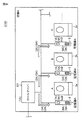
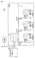
(1) 本発明は、遊技場に設置される遊技機(パチンコ機、スロットマシン、封入循環式パチンコ機(P台2)、メダル不要のスロットマシン(S台2S))と、前記遊技機に接続された遊技用装置(CU3、呼出しランプ装置など)と、複数の前記遊技用装置に接続され、前記遊技機および前記遊技用装置を管理する管理装置(たとえば、店舗外の鍵管理サーバ800や管理センタ、店舗内のホールサーバ801やホールコンなど)とを備える遊技用システムであって、
前記遊技場の営業終了時刻を特定可能な情報を少なくとも含む営業情報を設定する設定手段(図31(1),図34(1A):ホールサーバ801、図35(1B):管理センタ800B、なお、設定手段における営業情報の設定は、たとえば営業終了時刻を入力して登録するなど営業情報の内容を設定することをいう)と、
前記設定手段により設定された前記営業情報に基づいて(たとえば、あらかじめ記憶してある前記営業情報を判定基準としても、判定を行なう際に前記設定手段に問い合わせた営業情報を判定基準としてもよい)、現時刻が前記営業終了時刻を経過したか否かを判定する判定手段(図31(2),図35(2B):ホールサーバ801、図34(3A):CU3)と、
前記判定手段により現時刻が前記営業終了時刻を経過したと判定された場合に、前記営業終了時刻を経過したことを示す営業終了情報(たとえば、営業終了フラグ情報や営業終了時刻情報など)を前記遊技機に送信する送信手段(図31(3),図35(3B):ホールサーバ801、図34(4A):CU3)とを備え、
前記遊技機は、
前記送信手段により送信された前記営業終了情報を受信する受信手段(P台2で受信)と、
前記営業終了情報に基づいて、前記遊技場の営業が終了したことを報知する報知手段(たとえば、P台2の可変表示装置278またはCU3の表示器312に営業終了画像を表示したり、P台2のスピーカ270から終了音声を出力したりする)とを備える。
(1) The present invention relates to a gaming machine (pachinko machine, slot machine, sealed circulation pachinko machine (P 2), slot machine without medals (S 2S)) installed in a game hall, and the gaming machine A connected gaming device (CU3, call lamp device, etc.) and a management device (for example, a
Setting means for setting sales information including at least information capable of specifying the business end time of the game hall (FIG. 31 (1), FIG. 34 (1A):
Based on the sales information set by the setting unit (for example, the sales information stored in advance may be used as a determination criterion, or the sales information inquired to the setting unit at the time of determination may be used as a determination criterion). Determining means for determining whether or not the current time has passed the business end time (FIG. 31 (2), FIG. 35 (2B):
When the determination means determines that the current time has passed the business end time, the business end information (for example, business end flag information or business end time information) indicating that the business end time has passed is Transmission means (FIG. 31 (3), FIG. 35 (3B):
The gaming machine is
Receiving means for receiving the business end information transmitted by the transmitting means (received by the P unit 2);
Based on the end-of-business information, notification means for notifying that the game hall has ended (for example, displaying an end-of-business image on the
上記構成によれば、営業終了情報が遊技機に送信され、遊技場の営業が終了したことを遊技機が報知するので、遊技者に遊技場の営業が終了したことを認識させて、営業時間外に遊技機が稼働することを防止することができる。 According to the above configuration, the closing information is transmitted to the gaming machine, and the gaming machine notifies the closing of the game hall, so that the player recognizes the closing of the gaming hall and the opening hours. It is possible to prevent the gaming machine from operating outside.
(2) 本発明は、遊技場に設置される遊技機(パチンコ機、スロットマシン、封入循環式パチンコ機(P台2)、メダル不要のスロットマシン(S台2S))と、前記遊技機に接続された遊技用装置(CU3、呼出しランプ装置など)と、複数の前記遊技用装置に接続され、前記遊技機および前記遊技用装置を管理する管理装置(たとえば、店舗外の鍵管理サーバ800や管理センタ、店舗内のホールサーバ801やホールコンなど)とを備える遊技用システムであって、
前記遊技場の営業終了時刻を特定可能な情報を少なくとも含む営業情報を設定する設定手段(図31(1),図34(1A):ホールサーバ801、図35(1B):管理センタ800B、なお、設定手段における営業情報の設定は、たとえば営業終了時刻を入力して登録するなど営業情報の内容を設定することをいう)と、
前記設定手段により設定された前記営業情報に基づいて(たとえば、あらかじめ記憶してある前記営業情報を判定基準としても、判定を行なう際に前記設定手段に問い合わせた営業情報を判定基準としてもよい)、現時刻が前記営業終了時刻を経過したか否かを判定する判定手段(図31(2),図35(2B):ホールサーバ801、図34(3A):CU3)と、
前記判定手段により現時刻が前記営業終了時刻を経過したと判定された場合に、前記営業終了時刻を経過したことを示す営業終了情報(たとえば、営業終了フラグ情報や営業終了時刻情報など)を前記遊技機に送信する送信手段(図31(3),図35(3B):ホールサーバ801、図34(4A):CU3)とを備え、
前記遊技機は、
前記送信手段により送信された前記営業終了情報を受信する受信手段(P台2で受信)と、
前記営業終了情報に基づいて、前記遊技機での遊技を制限する制限手段(たとえば、P台2の発射モータ18を制御して遊技玉の発射を停止したり、玉貸ボタン321を押下しても遊技玉への貸出を禁止したり、P台2の可変表示装置278での図柄変動を停止させたりする。)とを備える。
(2) The present invention relates to a gaming machine (pachinko machine, slot machine, sealed circulation pachinko machine (P 2), slot machine without medals (S 2S)) installed in a game hall, and the gaming machine A connected gaming device (CU3, call lamp device, etc.) and a management device (for example, a
Setting means for setting sales information including at least information capable of specifying the business end time of the game hall (FIG. 31 (1), FIG. 34 (1A):
Based on the sales information set by the setting unit (for example, the sales information stored in advance may be used as a determination criterion, or the sales information inquired to the setting unit at the time of determination may be used as a determination criterion). Determining means for determining whether or not the current time has passed the business end time (FIG. 31 (2), FIG. 35 (2B):
When the determination means determines that the current time has passed the business end time, the business end information (for example, business end flag information or business end time information) indicating that the business end time has passed is Transmission means (FIG. 31 (3), FIG. 35 (3B):
The gaming machine is
Receiving means for receiving the business end information transmitted by the transmitting means (received by the P unit 2);
Based on the end-of-business information, limiting means for limiting the game on the gaming machine (for example, controlling the
上記構成によれば、営業終了情報が遊技機に送信され、遊技機での遊技を制限するので、遊技者に遊技場の営業が終了したことを認識させるとともに、営業時間外に遊技機が稼働することを防止することができる。 According to the above configuration, the business end information is transmitted to the gaming machine and the game on the gaming machine is restricted, so that the player can recognize that the business of the game hall has ended and the gaming machine is operated outside the business hours. Can be prevented.
(3) 上記(1)または(2)において、
前記受信手段により受信した前記営業終了情報を記憶する記憶手段(図31,図35:記憶部E、図34:記憶部A)をさらに備え、
前記報知手段は、前記記憶手段に記憶されている前記営業終了情報に基づいて、前記遊技場の営業が終了したことを報知する。
(3) In the above (1) or (2),
Storage means (FIG. 31, FIG. 35: storage unit E, FIG. 34: storage unit A) for storing the business end information received by the reception unit,
The notification means notifies that the game hall has ended based on the business end information stored in the storage means.
上記構成によれば、送信されてきた営業終了情報を記憶するので、当該記憶が消去されるまで遊技場の営業が終了したことを報知することができ、営業時間外に遊技機が稼働することを防止することができる。特に、遊技機に記憶手段を設けた場合、たとえ営業終了情報が送信された後に遊技用装置から遊技機を取外しても、遊技場の営業が終了したことを報知することができる。 According to the above configuration, since the transmitted business end information is stored, it is possible to notify that the game hall business has ended until the storage is erased, and that the gaming machine operates outside business hours. Can be prevented. In particular, when a storage device is provided in a gaming machine, even if the gaming machine is removed from the gaming device after the closing information is transmitted, it can be notified that the game hall has been closed.
(4) 上記(1)または(2)において、
前記受信手段により受信した前記営業終了情報を記憶する記憶手段(図31,図35:記憶部E、図34:記憶部A)をさらに備え、
前記制限手段は、前記記憶手段に記憶されている前記営業終了情報に基づいて、前記遊技機での遊技を制限する。
(4) In the above (1) or (2),
Storage means (FIG. 31, FIG. 35: storage unit E, FIG. 34: storage unit A) for storing the business end information received by the reception unit,
The restricting means restricts a game in the gaming machine based on the business end information stored in the storage means.
上記構成によれば、送信されてきた営業終了情報を記憶するので、当該記憶が消去されるまで遊技機での遊技を制限することができ、営業時間外に遊技機が稼働することを防止することができる。特に、遊技機に記憶手段を設けた場合、たとえ営業終了情報が送信された後に遊技用装置から遊技機を取外しても、遊技機での遊技を制限することができる。 According to the above configuration, since the transmitted business end information is stored, it is possible to limit gaming at the gaming machine until the memory is erased, and prevent the gaming machine from operating outside business hours. be able to. In particular, in the case where a storage unit is provided in the gaming machine, even if the gaming machine is removed from the gaming device after the closing information is transmitted, the gaming in the gaming machine can be limited.
(5) 上記(1)において、
前記設定手段は、前記営業情報に前記遊技場の営業開始時刻を特定可能な情報も含めて設定(図31(1),図34(1A):ホールサーバ801、図35(1B):管理センタ800B)し、
前記判定手段は、前記営業情報に基づいて、現時刻が前記遊技場の前記営業開始時刻か否かをさらに判定(図31(5):ホールサーバ801、図34(6A):CU3、図35(5B):管理センタ800B)し、
前記送信手段は、前記判定手段により現時刻が前記営業開始時刻であると判定された場合に、前記営業開始時刻となったことを示す営業開始情報(たとえば、営業開始フラグ情報や営業開始時刻情報など)を前記遊技機に送信(図31(6),図35(6B):ホールサーバ801、図34(7A):CU3)し、
前記報知手段は、前記送信手段により送信された前記営業開始情報に基づいて、前記遊技場の営業が終了したことの報知を止める。
(5) In the above (1),
The setting means sets the sales information including information that can specify the business start time of the game hall (FIG. 31 (1), FIG. 34 (1A):
The determination means further determines whether or not the current time is the business start time of the game hall based on the business information (FIG. 31 (5):
The transmission means, when the determination means determines that the current time is the business start time, the business start information (for example, business start flag information and business start time information indicating that the business start time has been reached) Etc.) (FIG. 31 (6), FIG. 35 (6B):
The notification means stops notification that the game hall has ended based on the business start information transmitted by the transmission means.
上記構成によれば、営業開始情報が遊技機に送信され、遊技場の営業が終了したことの報知を止めるので、営業開始情報が遊技機に送信されるまで、遊技機が稼働することを防止することができる。 According to the above configuration, since the business start information is transmitted to the gaming machine and the notification that the game hall business has ended is stopped, the gaming machine is prevented from operating until the business start information is transmitted to the gaming machine. can do.
(6) 上記(2)において、
前記設定手段は、前記営業情報に前記遊技場の営業開始時刻を特定可能な情報も含めて設定(図31(1),図34(1A):ホールサーバ801、図35(1B):管理センタ800B)し、
前記判定手段は、前記営業情報に基づいて、現時刻が前記遊技場の前記営業開始時刻か否かをさらに判定(図31(5):ホールサーバ801、図34(6A):CU3、図35(5B):管理センタ800B)し、
前記送信手段は、前記判定手段により現時刻が前記営業開始時刻であると判定された場合に、前記営業開始時刻となったことを示す営業開始情報(たとえば、営業開始フラグ情報や営業開始時刻情報など)を前記遊技機に送信(図31(6),図35(6B):ホールサーバ801、図34(7A):CU3)し、
前記制限手段は、前記送信手段により送信された前記営業開始情報に基づいて、前記遊技機での遊技の制限を解除する。
(6) In (2) above,
The setting means sets the sales information including information that can specify the business start time of the game hall (FIG. 31 (1), FIG. 34 (1A):
The determination means further determines whether or not the current time is the business start time of the game hall based on the business information (FIG. 31 (5):
The transmission means, when the determination means determines that the current time is the business start time, the business start information (for example, business start flag information and business start time information indicating that the business start time has been reached) Etc.) (FIG. 31 (6), FIG. 35 (6B):
The restriction means releases the restriction on the game machine based on the business start information transmitted by the transmission means.
上記構成によれば、営業開始情報が遊技機に送信され、遊技機での遊技の制限を解除するので、営業開始情報が遊技機に送信されるまで、遊技機が稼働することを防止することができる。 According to the above configuration, since the business start information is transmitted to the gaming machine and the restriction of the game on the gaming machine is released, the gaming machine is prevented from operating until the business start information is transmitted to the gaming machine. Can do.
(7) 上記(1)において、
前記遊技機は、
遊技状態が遊技者にとって有利な特定遊技状態(たとえば、大当り状態、確変状態や、時短状態など)に基づき、前記報知手段での報知態様を変更する報知態様変更手段(たとえば、可変表示装置278に表示している営業終了画像を小さくするなど)をさらに備える。
(7) In (1) above,
The gaming machine is
Based on a specific gaming state in which the gaming state is advantageous for the player (for example, a big hit state, a probable change state, a short time state, etc.), the notification mode changing means (for example, the
上記構成によれば、特定遊技状態に基づき、報知手段での報知態様を変更するので、遊技者に不利益を与えることなく、遊技場の営業が終了したことを報知することが可能になる。 According to the above configuration, since the notification mode of the notification means is changed based on the specific game state, it is possible to notify that the business of the game hall has ended without detriment to the player.
(8) 上記(2)において、
前記遊技機は、
遊技状態が遊技者にとって有利な特定遊技状態(たとえば、大当り状態、確変状態や、時短状態など)に基づき、前記制限手段での制限内容を変更する制限内容変更手段(たとえば、演出画像を可変表示装置278で表示する時間を短くするなど)をさらに備える。
(8) In (2) above,
The gaming machine is
Restricted content changing means (for example, effect image is variably displayed) for changing the restricted content in the restricting means based on a specific gaming state (for example, a big hit state, a probable change state, a short time state, etc.) where the gaming state is advantageous to the player And the like.
上記構成によれば、特定遊技状態に基づき、報知手段での報知態様を変更するので、遊技者に不利益を与えることなく、遊技場の営業が終了したことを報知することが可能になる。 According to the above configuration, since the notification mode of the notification means is changed based on the specific game state, it is possible to notify that the business of the game hall has ended without detriment to the player.
(9) 上記(3)において、
前記記憶手段は、前記遊技機により検知可能な操作(たとえば、P台2の電源ON操作、ガラス扉6または前枠5の開閉操作など)が行なわれたか否かを示す操作履歴情報をさらに記憶する。
(9) In (3) above,
The storage means further stores operation history information indicating whether or not an operation that can be detected by the gaming machine (for example, a power-on operation of the
上記構成によれば、営業時間外に遊技機が稼働することを防止することができるとともに、営業時間外に遊技機に対して行なわれた操作(たとえばガラス扉6の開放など)を記憶することができる。 According to the above configuration, it is possible to prevent the gaming machine from operating outside the business hours, and to store an operation performed on the gaming machine outside the business hours (for example, opening the glass door 6). Can do.
(10) 本発明は、遊技場に設置される遊技機(パチンコ機、スロットマシン、封入循環式パチンコ機(P台2)、メダル不要のスロットマシン(S台2S))に接続された遊技用装置(CU3、呼出しランプ装置など)であって、
前記遊技場の営業終了時刻を特定可能な情報を少なくとも含む営業情報を設定する設定手段(CU3に営業情報を設定する、なお、設定手段における営業情報の設定は、たとえば営業終了時刻を入力して登録するなど営業情報の内容を設定することをいう)と、
前記設定手段により設定された前記営業情報に基づいて(たとえば、あらかじめ記憶してある前記営業情報を判定基準としても、判定を行なう際に前記設定手段に問い合わせた営業情報を判定基準としてもよい)、現時刻が前記営業終了時刻を経過したか否かを判定する判定手段(図34(3A):CU3)と、
前記判定手段により現時刻が前記営業終了時刻を経過したと判定された場合に、前記営業終了時刻の経過を報知させるための営業終了情報を前記遊技機に送信する送信手段(図34(4A):CU3)とを備える。
(10) The present invention is for games connected to gaming machines (pachinko machines, slot machines, enclosed circulation pachinko machines (P 2), slot machines without medals (S 2S)) installed in the game hall. A device (CU3, call lamp device, etc.),
Setting means for setting sales information including at least information capable of specifying the business end time of the amusement hall (setting sales information in the CU3. The setting of sales information in the setting means is performed by, for example, inputting the business end time. Setting the contents of sales information such as registration)
Based on the sales information set by the setting unit (for example, the sales information stored in advance may be used as a determination criterion, or the sales information inquired to the setting unit at the time of determination may be used as a determination criterion). Determining means (FIG. 34 (3A): CU3) for determining whether or not the current time has passed the business end time;
Transmission means for transmitting to the gaming machine business end information for notifying the elapse of the business end time when the determination means determines that the current time has passed the business end time (FIG. 34 (4A)). : CU3).
上記構成によれば、営業終了情報が遊技機に送信され、遊技場の営業が終了したことを遊技機が報知するので、遊技者に遊技場の営業が終了したことを認識させて、営業時間外に遊技機が稼働することを防止することができる。 According to the above configuration, the closing information is transmitted to the gaming machine, and the gaming machine notifies the closing of the game hall, so that the player recognizes the closing of the gaming hall and the opening hours. It is possible to prevent the gaming machine from operating outside.
(11) 本発明は、遊技場に設置される遊技機(パチンコ機、スロットマシン、封入循環式パチンコ機(P台2)、メダル不要のスロットマシン(S台2S))、および前記遊技機に接続された遊技用装置(CU3、呼出しランプ装置など)を管理し、複数の前記遊技用装置に接続された管理装置(たとえば、店舗外の鍵管理サーバ800や管理センタ、店舗内のホールサーバ801やホールコンなど)であって、
前記遊技場の営業終了時刻を特定可能な情報を少なくとも含む営業情報を設定する設定手段(図31(1):ホールサーバ801、なお、設定手段における営業情報の設定は、たとえば営業終了時刻を入力して登録するなど営業情報の内容を設定することをいう)と、
前記設定手段により設定された前記営業情報に基づいて(たとえば、あらかじめ記憶してある前記営業情報を判定基準としても、判定を行なう際に前記設定手段に問い合わせた営業情報を判定基準としてもよい)、現時刻が前記営業終了時刻を経過したか否かを判定する判定手段(図31(2):ホールサーバ801)と、
前記判定手段により現時刻が前記営業終了時刻を経過したと判定された場合に、前記営業終了時刻の経過を報知させるための営業終了情報を前記遊技機に送信する送信手段(図31(3):ホールサーバ801)とを備える。
(11) The present invention relates to a gaming machine (pachinko machine, slot machine, sealed circulation pachinko machine (P 2), slot machine without medals (S 2S)) installed in a game hall, and the gaming machine A management device (for example, a
Setting means for setting sales information including at least information capable of specifying the business end time of the amusement hall (FIG. 31 (1): hall server 801). And setting the contents of sales information such as registering)
Based on the sales information set by the setting unit (for example, the sales information stored in advance may be used as a determination criterion, or the sales information inquired to the setting unit at the time of determination may be used as a determination criterion). Determination means (FIG. 31 (2): hall server 801) for determining whether or not the current time has passed the business end time;
Transmitting means for transmitting, to the gaming machine, business end information for notifying the elapse of the business end time when the determination means determines that the current time has passed the business end time (FIG. 31 (3)). : Hall server 801).
上記構成によれば、営業終了情報が遊技機に送信され、遊技場の営業が終了したことを遊技機が報知するので、遊技者に遊技場の営業が終了したことを認識させて、営業時間外に遊技機が稼働することを防止することができる。 According to the above configuration, the closing information is transmitted to the gaming machine, and the gaming machine notifies the closing of the game hall, so that the player recognizes the closing of the gaming hall and the opening hours. It is possible to prevent the gaming machine from operating outside.
(12) 本発明は、遊技場に設置される遊技機(パチンコ機、スロットマシン、封入循環式パチンコ機(P台2)、メダル不要のスロットマシン(S台2S))に接続された遊技用装置(CU3、呼出しランプ装置など)であって、
前記遊技場の営業終了時刻を特定可能な情報を少なくとも含む営業情報を設定する設定手段(CU3に営業情報を設定する、なお、設定手段における営業情報の設定は、たとえば営業終了時刻を入力して登録するなど営業情報の内容を設定することをいう)と、
前記設定手段により設定された前記営業情報に基づいて(たとえば、あらかじめ記憶してある前記営業情報を判定基準としても、判定を行なう際に前記設定手段に問い合わせた営業情報を判定基準としてもよい)、現時刻が前記営業終了時刻を経過したか否かを判定する判定手段(図34(3A):CU3)と、
前記判定手段により現時刻が前記営業終了時刻を経過したと判定された場合に、前記遊技機での遊技を制限させるための営業終了情報を前記遊技機に送信する送信手段(図34(4A):CU3)とを備える。
(12) The present invention is for a game machine connected to a gaming machine (pachinko machine, slot machine, sealed circulation pachinko machine (P 2), medal-free slot machine (S 2S)) installed in a game hall. A device (CU3, call lamp device, etc.),
Setting means for setting sales information including at least information capable of specifying the business end time of the amusement hall (setting sales information in the CU3. The setting of sales information in the setting means is performed by, for example, inputting the business end time. Setting the contents of sales information such as registration)
Based on the sales information set by the setting unit (for example, the sales information stored in advance may be used as a determination criterion, or the sales information inquired to the setting unit at the time of determination may be used as a determination criterion). Determining means (FIG. 34 (3A): CU3) for determining whether or not the current time has passed the business end time;
Transmitting means for transmitting, to the gaming machine, business end information for restricting a game on the gaming machine when the determining means determines that the current time has passed the business ending time (FIG. 34 (4A)). : CU3).
上記構成によれば、営業終了情報が遊技機に送信され、遊技機での遊技を制限するので、遊技者に遊技場の営業が終了したことを認識させて、営業時間外に遊技機が稼働することを防止することができる。 According to the above configuration, the business end information is transmitted to the gaming machine and the game on the gaming machine is restricted, so that the player recognizes that the business of the game hall has ended, and the gaming machine operates outside the business hours. Can be prevented.
(13) 本発明は、遊技場に設置される遊技機(パチンコ機、スロットマシン、封入循環式パチンコ機(P台2)、メダル不要のスロットマシン(S台2S))、および前記遊技機に接続された遊技用装置(CU3、呼出しランプ装置など)を管理し、複数の前記遊技用装置に接続された管理装置(たとえば、店舗外の鍵管理サーバ800や管理センタ、店舗内のホールサーバ801やホールコンなど)であって、
前記遊技場の営業終了時刻を特定可能な情報を少なくとも含む営業情報を設定する設定手段(図31(1):ホールサーバ801、なお、設定手段における営業情報の設定は、たとえば営業終了時刻を入力して登録するなど営業情報の内容を設定することをいう)と、
前記設定手段により設定された前記営業情報に基づいて(たとえば、あらかじめ記憶してある前記営業情報を判定基準としても、判定を行なう際に前記設定手段に問い合わせた営業情報を判定基準としてもよい)、現時刻が前記営業終了時刻を経過したか否かを判定する判定手段(図31(2):ホールサーバ801)と、
前記判定手段により現時刻が前記営業終了時刻を経過したと判定された場合に、前記遊技機での遊技を制限させるための営業終了情報を前記遊技機に送信する送信手段(図31(3):ホールサーバ801)とを備える。
(13) The present invention relates to a gaming machine (pachinko machine, slot machine, sealed circulation pachinko machine (P 2), slot machine without medals (S 2S)) installed in a game hall, and the gaming machine A management device (for example, a
Setting means for setting sales information including at least information capable of specifying the business end time of the amusement hall (FIG. 31 (1): hall server 801). And setting the contents of sales information such as registering)
Based on the sales information set by the setting unit (for example, the sales information stored in advance may be used as a determination criterion, or the sales information inquired to the setting unit at the time of determination may be used as a determination criterion). Determination means (FIG. 31 (2): hall server 801) for determining whether or not the current time has passed the business end time;
When the determination means determines that the current time has passed the business end time, transmission means for transmitting business end information for restricting a game in the gaming machine to the gaming machine (FIG. 31 (3)) : Hall server 801).
上記構成によれば、営業終了情報が遊技機に送信され、遊技機での遊技を制限するので、遊技者に遊技場の営業が終了したことを認識させて、遊技者に遊技場の営業が終了したことを認識させて、営業時間外に遊技機が稼働することを防止することができる。 According to the above configuration, since the closing information is transmitted to the gaming machine and the gaming on the gaming machine is restricted, the player is made aware that the gaming hall has been closed and the player is allowed to operate the gaming hall. Recognizing that the game has ended, it is possible to prevent the gaming machine from operating outside business hours.
(1−1) 本発明は、入賞の発生により所定の遊技点を付与する遊技機(P台2)と、前記遊技機と通信可能に接続され、遊技者所有の有価価値を用いて前記遊技機での遊技を可能にする遊技用装置(CU3)とを備える遊技用システムであって、
前記遊技機は、
前記遊技点を記憶する遊技点記憶手段(図6:遊技玉数カウンタ)と、
前記遊技点を所定の持点に計数するための操作(たとえば、図13に示す「計数」ボタン押下)に基づいて、前記遊技点記憶手段に記憶する前記遊技点を前記持点に計数する計数要求を前記遊技用装置へ送信する計数要求送信手段(図13:P台2は、計数開始時の計数玉の払出要求がある場合、計数要求=ONの情報を含む状態情報応答のコマンドをCU3に送信する。)とを含み、
前記遊技用装置は、
前記計数要求送信手段からの前記計数要求に基づき、前記遊技点を前記持点に計数する計数処理手段(図13:CU3は、計数要求=ONの情報を含む状態情報応答を受信すると、要求されている計数玉数を持玉数に加算する。)と、
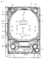
遊技者所有の有価価値を特定可能な記録媒体を受付ける記録媒体受付手段(図1:カードを受け付けるカード挿入/排出口309)と、
前記計数処理手段で計数した前記持点を前記記録媒体受付手段で受付けた前記記録媒体で特定可能に処理する記録媒体処理手段(図13:CU3は、カード挿入/排出口309に挿入してあったカードに持玉数を記憶させる。)と、
前記記録媒体処理手段で処理された記録媒体を返却する記録媒体返却手段(図13:CU3は、持玉数を記憶させたカードを返却する。)と、
前記記録媒体返却手段により返却された前記記録媒体の取り外し待ち状態であることを前記遊技機に通知する取り外し待ち状態通知手段(図13:CU3は、カード抜き取り可能状態となった場合、カード返却準備状態OFFおよびカード抜き取り待ち中ONの情報をP台2に通知する。)とを含む。
(1-1) The present invention is connected to a gaming machine (P 2) that gives a predetermined gaming point by the occurrence of a prize, and the gaming machine so as to be communicable, and uses the valuable value possessed by the player. A gaming system comprising a gaming device (CU3) that enables gaming on a machine,
The gaming machine is
Game point storage means for storing the game points (FIG. 6: game ball counter);
Count for counting the game points stored in the game point storage means based on an operation for counting the game points to a predetermined score (for example, pressing the “count” button shown in FIG. 13). Count request transmission means for transmitting a request to the gaming device (FIG. 13: P table 2 sends a status information response command including information of count request = ON when there is a count ball payout request at the start of counting. To send to
The gaming device is:
Based on the counting request from the counting request transmission means, counting processing means for counting the gaming points to the points (FIG. 13: CU3 is requested when receiving a status information response including information of counting request = ON. The number of counting balls is added to the number of holding balls)
A recording medium receiving means (FIG. 1: a card insertion / ejecting
Recording medium processing means (FIG. 13: CU3 is inserted into the card insertion / ejection slot 309) for processing the holding points counted by the counting processing means so as to be specified by the recording medium received by the recording medium receiving means. Memorize the number of balls in the card.),
Recording medium return means for returning the recording medium processed by the recording medium processing means (FIG. 13: CU3 returns a card storing the number of possessed balls);
Removal waiting state notifying means for notifying the gaming machine that the recording medium returned by the recording medium returning means is waiting to be removed (FIG. 13: CU3 prepares for card return when card removal is possible) Information on status OFF and card waiting for card removal ON is sent to the P stand 2).
上記構成によれば、記録媒体返却手段により返却された記録媒体が取り外し待ち状態であることを、取り外し待ち状態通知手段が遊技機に通知するので、遊技機が遊技者に対して記録媒体の取り外しを促す報知を行なうことが可能となり、記録媒体の取り外し忘れを防止することができる。また、記録媒体の取り外し忘れによる盗難防止のための注意喚起を行なうことができる。 According to the above configuration, the removal waiting state notifying means notifies the gaming machine that the recording medium returned by the recording medium returning means is waiting for removal, so that the gaming machine removes the recording medium from the player. Can be notified, and forgetting to remove the recording medium can be prevented. In addition, it is possible to call attention to prevent theft caused by forgetting to remove the recording medium.
(1−2) 本発明は、入賞の発生により所定の遊技点を付与する遊技機(P台2)と通信可能に接続され、遊技者所有の有価価値を用いて前記遊技機での遊技を可能にする遊技用装置(CU3)であって、
前記遊技機からの計数要求に基づき、前記遊技点を持点に計数する計数処理手段(図13:CU3は、計数要求=ONの情報を含む状態情報応答を受信すると、要求されている計数玉数を持玉数に加算する。)と、
遊技者所有の有価価値を特定可能な記録媒体を受付ける記録媒体受付手段(図1:カードを受け付けるカード挿入/排出口309)と、
前記計数処理手段で計数した前記持点を前記記録媒体受付手段で受付けた前記記録媒体で特定可能に処理する記録媒体処理手段(図13:CU3は、カード挿入/排出口309に挿入してあったカードに持玉数を記憶させる。)と、
前記記録媒体処理手段で処理された記録媒体を返却する記録媒体返却手段(図13:CU3は、持玉数を記憶させたカードを返却する。)と、
前記記録媒体返却手段により返却された前記記録媒体の取り外し待ち状態であることを前記遊技機に通知する取り外し待ち状態通知手段(図13:CU3は、カード抜き取り可能状態となった場合、カード返却準備状態OFFおよびカード抜き取り待ち中ONの情報をP台2に通知する。)とを備える。
(1-2) The present invention is communicably connected to a gaming machine (P unit 2) that gives a predetermined gaming point when a winning occurs, and uses the valuable value owned by the player to play a game in the gaming machine. A gaming device (CU3) that enables
Count processing means for counting the gaming points based on the counting request from the gaming machine (FIG. 13: When the CU3 receives a status information response including information of counting request = ON, the requested counting ball And add the number to the number of balls.)
A recording medium receiving means (FIG. 1: a card insertion / ejecting
Recording medium processing means (FIG. 13: CU3 is inserted into the card insertion / ejection slot 309) for processing the holding points counted by the counting processing means so as to be specified by the recording medium received by the recording medium receiving means. Memorize the number of balls in the card.),
Recording medium return means for returning the recording medium processed by the recording medium processing means (FIG. 13: CU3 returns a card storing the number of possessed balls);
Removal waiting state notifying means for notifying the gaming machine that the recording medium returned by the recording medium returning means is waiting to be removed (FIG. 13: CU3 prepares for card return when card removal is possible) The P table 2 is notified of information indicating that the state is OFF and the card is waiting to be removed.).
上記構成によれば、記録媒体返却手段により返却された記録媒体が取り外し待ち状態であることを、取り外し待ち状態通知手段が遊技機に通知するので、遊技機が遊技者に対して記録媒体の取り外しを促す報知を行なうことが可能となり、記録媒体の取り外し忘れを防止することができる。また、記録媒体の取り外し忘れによる盗難防止のための注意喚起を行なうことができる。 According to the above configuration, the removal waiting state notifying means notifies the gaming machine that the recording medium returned by the recording medium returning means is waiting for removal, so that the gaming machine removes the recording medium from the player. Can be notified, and forgetting to remove the recording medium can be prevented. In addition, it is possible to call attention to prevent theft caused by forgetting to remove the recording medium.
(1−3) 本発明は、遊技者所有の有価価値を用いて遊技を可能にする遊技用装置(CU3)と通信可能に接続され、入賞の発生により所定の遊技点を付与する遊技機(P台2)であって、
前記遊技点を記憶する遊技点記憶手段(図6:遊技玉数カウンタ)と、
前記遊技点を所定の持点に計数するための操作(たとえば、図13に示す「計数」ボタン押下)に基づいて、前記遊技点記憶手段に記憶する前記遊技点を前記持点に計数する計数要求を前記遊技用装置へ送信する計数要求送信手段(図13:P台2は、計数開始時の計数玉の払出要求がある場合、計数要求=ONの情報を含む状態情報応答のコマンドをCU3に送信する。)とを備え、
前記計数要求送信手段からの前記計数要求に基づき計数した前記持点を、前記遊技用装置で受付けた記録媒体で特定可能に処理し、前記記録媒体を返却する場合に、前記記録媒体の取り外し待ち状態であることの通知を前記遊技用装置から受付可能(図13:P台2は、カード抜き取り可能状態となった場合、カード返却準備状態OFFおよびカード抜き取り待ち中ONの情報の通知をCU3から受ける。)である。
(1-3) The present invention is connected to a gaming device (CU3) that enables a game using a valuable value owned by a player so as to be communicable, and gives a predetermined gaming point when a winning occurs ( P stand 2)
Game point storage means for storing the game points (FIG. 6: game ball counter);
Count for counting the game points stored in the game point storage means based on an operation for counting the game points to a predetermined score (for example, pressing the “count” button shown in FIG. 13). Count request transmission means for transmitting a request to the gaming device (FIG. 13: P table 2 sends a status information response command including information of count request = ON when there is a count ball payout request at the start of counting. To send to
When the points counted based on the counting request from the counting request transmission means are processed in a manner that can be specified by the recording medium received by the gaming device, and the recording medium is returned, the recording medium is awaiting removal. A notification that the card is ready can be received from the gaming device (FIG. 13: When the
上記構成によれば、記録媒体返却手段により返却された記録媒体が取り外し待ち状態であることの通知を、前記遊技用装置から受けるので、遊技機が遊技者に対して記録媒体の取り外しを促す報知を行なうことが可能となり、記録媒体の取り外し忘れを防止することができる。また、記録媒体の取り外し忘れによる盗難防止のための注意喚起を行なうことができる。 According to the above configuration, since the game device receives a notification that the recording medium returned by the recording medium return means is in a removal waiting state, the game machine prompts the player to remove the recording medium. This makes it possible to prevent forgetting to remove the recording medium. In addition, it is possible to call attention to prevent theft caused by forgetting to remove the recording medium.
(1−4) 上記(1−1)〜(1−3)において、
前記遊技用装置は、前記記録媒体の取り外し待ち状態であることを報知する報知手段(たとえば、図1に示す表示器312)を含む。
(1-4) In the above (1-1) to (1-3),
The gaming device includes notification means (for example, the
上記構成によれば、遊技用装置でも記録媒体の取り外し待ち状態であることを報知することが可能となるので、記録媒体の取り外し忘れを防止することができる。 According to the above configuration, it is possible to notify the gaming device that the recording medium is waiting to be removed, so that it is possible to prevent forgetting to remove the recording medium.
(1−5) 上記(1−1)〜(1−3)において、
前記遊技機は、前記遊技用装置からの通知に基づき、前記記録媒体の取り外し待ち状態であることを報知する表示手段(たとえば、図1に示す可変表示装置278)を含む。
(1-5) In the above (1-1) to (1-3),
The gaming machine includes display means (for example, a
上記構成によれば、遊技機で記録媒体の取り外し待ち状態であることを視覚的に報知することが可能となるので、記録媒体の取り外し忘れを防止することができる。 According to the above configuration, since it is possible to visually notify the gaming machine that the recording medium is waiting to be removed, forgetting to remove the recording medium can be prevented.
(1−6) 上記(1−1)または(1−2)において、
前記取り外し待ち状態通知手段は、前記遊技用装置または前記遊技機に接続する装置(たとえば、ホールコンピュータ、P台上の呼び出しランプ)に対して、前記記録媒体の取り外し待ち状態であることを通知する。
(1-6) In the above (1-1) or (1-2),
The removal waiting state notification means notifies the gaming device or a device connected to the gaming machine (for example, a hall computer, a call lamp on P units) that the recording medium is waiting to be removed. .
上記構成によれば、遊技機や遊技用装置以外に対して記録媒体の取り外し待ち状態であることを通知することで、記録媒体の取り外し忘れを防止することができる。 According to the above configuration, it is possible to prevent the user from forgetting to remove the recording medium by notifying a device other than the gaming machine or gaming device that the recording medium is waiting to be removed.
(1−7) 本発明は、入賞の発生により所定の遊技点を付与する遊技機(P台2)と、前記遊技機と通信可能に接続され、遊技者所有の有価価値を用いて前記遊技機での遊技を可能にする遊技用装置(CU3)とを備える遊技用システムであって、
前記遊技用装置は、
遊技者所有の有価価値を特定可能な記録媒体を受付ける記録媒体受付手段(図1:カードを受け付けるカード挿入/排出口309)と、
前記記録媒体受付手段で前記記録媒体を受付けた場合に、前記遊技用装置が設置されている遊技場を特定可能な遊技場特定情報を前記遊技機に通知する遊技場特定情報通知手段(図9:カード挿入/排出口309でカードを受付けると、CU3は、セキュリティ基板325で付加された「店舗コード」を含むカード挿入通知コマンドを、P台2に対して送信する。)とを含み、
前記遊技機は、
前記遊技場特定情報通知手段により通知された前記遊技場特定情報を記憶する遊技場特定情報記憶手段(図9:P台2は、挿入通知コマンドに含まれる「店舗コード」を記憶する。)と、
前記遊技機と前記遊技用装置とが通信できない通信不能状態から回復した後、通信復旧した場合に、前記遊技場特定情報通知手段により新たに通知された前記遊技場特定情報と、前記遊技場特定情報記憶手段に記憶した前記遊技場特定情報と比較する遊技場特定情報比較手段(図14:P台2は、CU3から「店舗コード」を含むリカバリ要求が送信されてくると、当該「店舗コード」と記憶してある「店舗コード」とが一致するか否かを判定する。)と、
前記遊技場特定情報比較手段により、前記遊技場特定情報が不一致と判定された場合に遊技の継続を禁止する遊技禁止手段(P台2は、CU3からの「店舗コード」と、記憶してある「店舗コード」とが不一致の場合、遊技の継続を禁止する。)と
を含む。
(1-7) The present invention relates to a gaming machine (P 2) that gives a predetermined gaming point when a prize is generated, and is connected to the gaming machine in a communicable manner, and uses the valuable value owned by the player. A gaming system comprising a gaming device (CU3) that enables gaming on a machine,
The gaming device is:
A recording medium receiving means (FIG. 1: a card insertion / ejecting
When the recording medium is received by the recording medium receiving means, a game hall specifying information notifying means for notifying the gaming machine of game hall specifying information capable of specifying the game hall in which the gaming apparatus is installed (FIG. 9). When the card is received at the card insertion /
The gaming machine is
Game hall identification information storage means for storing the game hall identification information notified by the game hall identification information notification means (FIG. 9: P stand 2 stores “store code” included in the insertion notification command). ,
The game room specifying information newly notified by the game hall specifying information notifying means when the communication is restored after recovering from the communication incapable state where the gaming machine and the gaming device cannot communicate, and the game hall specifying When a recovery request including a “store code” is transmitted from the
The game prohibition means for prohibiting the continuation of the game when the game hall specific information comparison means determines that the game hall specific information is inconsistent (P table 2 stores “store code” from CU3. If the store code does not match, continuation of the game is prohibited.)
上記構成によれば、新たに通知された遊技場特定情報と、遊技場特定情報記憶手段に記憶した遊技場特定情報とが不一致の場合、遊技の継続を禁止するので、遊技媒体に計数玉を記憶させた状態で店舗を移動させる不正を防止することができる。 According to the above configuration, if the newly notified game hall specifying information and the game hall specifying information stored in the game hall specifying information storage means do not match, the continuation of the game is prohibited. It is possible to prevent fraud in which the store is moved in the stored state.
(1−8) 上記(1−7)において、
前記遊技用装置は、
前記記録媒体受付手段で前記記録媒体を受付けたとき、および前記通信復旧したときに、前記遊技用装置に含まれている遊技制御装置(たとえば、図4に示すセキュリティ基板325)を特定可能な装置特定情報(SC基板ID)を前記遊技機に通知する装置特定情報通知手段(図9:カード挿入/排出口309でカードを受付けると、CU3は、セキュリティ基板325で付加された「SC基板ID」を含むカード挿入通知コマンドを、P台2に対して送信する。)をさらに含み、
前記遊技機は、
前記装置特定情報通知手段により通知された前記装置特定情報を記憶する装置特定情報記憶手段(図9:P台2は、挿入通知コマンドに含まれる「SC基板ID」を記憶する。)と、
前記通信復旧した場合に、前記装置特定情報通知手段により新たに通知された前記装置特定情報と、前記装置特定情報記憶手段に記憶した前記装置特定情報と比較する装置特定情報比較手段P台2は、CU3からの「SC基板ID」と、記憶してある「SC基板ID」とを比較する。)とをさらに含み、
前記遊技禁止手段は、前記装置特定情報比較手段により、前記装置特定情報が不一致と判定された場合に遊技の継続を禁止する(不一致の場合、遊技の継続を禁止する。)。
(1-8) In the above (1-7),
The gaming device is:
A device capable of specifying a game control device (for example,
The gaming machine is
Device specifying information storage means for storing the device specifying information notified by the device specifying information notifying means (FIG. 9:
When the communication is restored, the device specifying information comparing
The game prohibiting means prohibits continuation of the game when the device specifying information comparing means determines that the device specifying information is inconsistent (in the case of mismatch, prohibiting continuation of the game).
上記構成によれば、新たに通知された装置特定情報と、装置特定情報記憶手段に記憶した装置特定情報とが不一致の場合、遊技の継続を禁止するので、遊技媒体に計数玉を記憶させた状態で遊技機を移動させる不正を防止することができる。 According to the above configuration, when the newly notified device identification information and the device identification information stored in the device identification information storage means do not match, the game is prohibited from being continued, so the counting balls are stored in the game medium. Unauthorized movement of the gaming machine in the state can be prevented.
(1−9) 上記(1−7)または上記(1−8)において、
前記遊技機は、
遊技に使用する遊技媒体に付加されている前記遊技場特定情報を読取る遊技場特定情報読取手段(たとえば、P台2の回収玉通過経路にセンサが設けてあり、当該センサが遊技玉に設けてある識別情報(表面の刻印など)を読取る。)をさらに含み、
前記遊技場特定情報比較手段は、前記遊技場特定情報読取手段で読取った前記遊技媒体に付加されている前記遊技場特定情報と、前記遊技場特定情報記憶手段に記憶した前記遊技場特定情報と比較する(読取った識別情報により、自店舗の遊技玉の識別情報と一致するか否かを判定して、不一致の場合、状態情報応答の「不正検知状態3」のBit0を、“1”にする。)。
(1-9) In the above (1-7) or (1-8) above,
The gaming machine is
A game hall specifying information reading means for reading the game hall specifying information added to the game medium used for the game (for example, a sensor is provided in the collection ball passage path of the
The game hall specifying information comparing means includes the game hall specifying information added to the game medium read by the game hall specifying information reading means, and the game hall specifying information stored in the game hall specifying information storage means. Compare (by the read identification information, it is determined whether or not it matches the identification information of the game ball of the own store, and in the case of a mismatch, the
上記構成によれば、遊技場特定情報読取手段で読取った遊技媒体に付加されている遊技場特定情報と、遊技場特定情報記憶手段に記憶した遊技場特定情報とが不一致であれば、遊技媒体に他店舗の遊技玉が混入していることを報知することが可能となる。 According to the above configuration, if the game hall identification information added to the game medium read by the game hall identification information reading means and the game hall identification information stored in the game hall identification information storage means do not match, the game medium It is possible to notify that game balls from other stores are mixed.
(2−1) 本発明は、入賞の発生により所定の遊技点を付与する遊技機(P台2、S台2S)と、該遊技機と通信可能に接続され、遊技者所有の有価価値(残高、貯玉、遊技玉数、現金など)を用いて該遊技機での遊技を可能にする遊技用装置(CU3)とを備える遊技用システムであって、
前記遊技用装置は、
遊技を行なう遊技者を特定する遊技者特定情報(C-ID(カードID)等)を読取る遊技者特定情報読取手段(カードリーダライタ)と、
該遊技者特定情報読取手段により読取られた遊技者特定情報を記憶する遊技者特定情報記憶手段(CU制御部323は、カードリーダライタで読み取ったカードIDを記憶)と、
遊技を開始するときに、前記遊技者特定情報読取手段により読取られた遊技者特定情報を前記遊技機へ送信する制御を行なう遊技者特定情報送信制御手段(図9のカード挿入通知によりカードIDを通知)とを含み、
前記遊技機は、
前記遊技者特定情報送信制御手段の制御により送信されてきた遊技者特定情報を記憶する記憶手段(図9:カードIDをバックアップ)と、
遊技を終了するときに、前記記憶手段に記憶されている遊技者特定情報を前記遊技用装置へ送信する制御を行なう送信制御手段(図13:P台2は、カード返却応答によって、バックアップしているC−IDを送信)と、
前記遊技点を記憶する遊技点記憶手段(図6の遊技玉数カウンタ)と、
前記遊技点を所定の持点に変換するための操作(計数)に基づいて前記遊技点を前記持点に変換するための変換要求を前記遊技用装置へ送信する変換要求送信手段(図13:P台2は、計数要求=ONの状態情報要求を送信)とを含み、
前記遊技用装置は、
前記変換要求送信手段から送信されてきた変換要求に基づいて前記遊技点を前記持点に変換するための変換処理を実行する(図13:計数玉数を持玉数に加算)とともに、前記変換要求を承諾した旨の変換承諾を前記遊技機へ返信する(図13:計数応答=ONの状態情報要求を送信)変換処理手段と、
前記送信制御手段の制御により送信されてきた遊技者特定情報と前記遊技者特定情報記憶手段に記憶されている遊技者特定情報とにより同一の遊技者が特定されるか否かを判定する同一判定手段(図13:CU3側でカード挿入時から記憶しているC−IDと、カード返却応答で通知されたC−IDとの一致判別)とをさらに含む。
(2-1) The present invention relates to a gaming machine (
The gaming device is:
Player specifying information reading means (card reader / writer) for reading player specifying information (C-ID (card ID) or the like) for specifying a player who performs a game;
Player identification information storage means for storing the player identification information read by the player identification information reading means (the
When starting a game, player identification information transmission control means for controlling to transmit the player identification information read by the player identification information reading means to the gaming machine (card ID is notified by card insertion notification in FIG. 9). Notification)
The gaming machine is
Storage means (FIG. 9: backup card ID) for storing player identification information transmitted under the control of the player identification information transmission control means;
When the game is finished, transmission control means for performing control for transmitting the player specifying information stored in the storage means to the gaming device (FIG. 13: P table 2 is backed up by a card return response. Send C-ID)
Game point storage means for storing the game points (game ball counter in FIG. 6);
Conversion request transmitting means for transmitting a conversion request for converting the gaming point to the holding point to the gaming device based on an operation (counting) for converting the gaming point into a predetermined holding point (FIG. 13: FIG. 13). P table 2 includes a count request = ON state information request is transmitted)
The gaming device is:
Based on the conversion request transmitted from the conversion request transmission means, a conversion process for converting the gaming points into the holding points is executed (FIG. 13: the number of counting balls is added to the number of holding balls) and the conversion is performed. A conversion processing means for returning a conversion approval indicating that the request has been accepted to the gaming machine (FIG. 13: sending a count response = ON state information request);
Identical determination for determining whether or not the same player is specified by the player specifying information transmitted by the control of the transmission control means and the player specifying information stored in the player specifying information storage means It further includes means (FIG. 13: coincidence determination between the C-ID stored from the time of card insertion on the CU3 side and the C-ID notified by the card return response).
このような構成によれば、変換操作に基づいて遊技点を持点に変換し、遊技機から送信されてきた遊技者特定情報と遊技開始時に記憶していた遊技者特定情報とにより同一の遊技者が特定されるか否かを判定することで遊技開始時の遊技者を特定する情報と遊技終了時の遊技者を特定する情報との同一性の判定を可能となる。また、その判定結果によって、遊技終了とすることが可能となり、遊技開始時の遊技者とは異なる遊技者によって遊技が終了されてしまう不都合を防止できる。 According to such a configuration, the game points are converted into points based on the conversion operation, and the same game is determined by the player specification information transmitted from the gaming machine and the player specification information stored at the start of the game. By determining whether or not the player is specified, it is possible to determine the identity between the information specifying the player at the start of the game and the information specifying the player at the end of the game. Further, it is possible to end the game based on the determination result, and it is possible to prevent the disadvantage that the game is ended by a player different from the player at the start of the game.
(2−2) 本発明は、入賞の発生により所定の遊技点を付与する遊技機(P台2、S台2S)と通信可能に接続するための接続部を備え、遊技者所有の有価価値(残高、貯玉、遊技玉数、現金など)を用いて該遊技機での遊技を可能にする遊技用装置(CU3)であって、
遊技を行なう遊技者を特定する遊技者特定情報(C-ID等)を読取る遊技者特定情報読取手段(カードリーダライタ)と、
該遊技者特定情報読取手段により読取られた遊技者特定情報を記憶する遊技者特定情報記憶手段(CU制御部323は、カードリーダライタで読み取ったカードIDを記憶)と、
遊技を開始するときに、前記遊技者特定情報読取手段により読取られた遊技者特定情報を前記遊技機へ送信する制御を行なう遊技者特定情報送信制御手段(図9のカード挿入通知によりカードIDを通知)と、
前記遊技者特定情報送信制御手段の制御により送信された遊技者特定情報を記憶した遊技機から、遊技を終了するときに送信されてきた遊技者特定情報と、前記遊技者特定情報記憶手段に記憶されている遊技者特定情報とにより、同一の遊技者が特定されるか否かを判定する同一判定手段(図13:CU3側でカード挿入時から記憶しているC−IDと、カード返却応答で通知されたC−IDとの一致判別)と、
前記遊技点を所定の持点に変換するための操作(計数操作)に基づいた前記遊技機からの変換要求に基づいて前記遊技点を前記持点に変換するための変換処理を実行する(図13:計数玉数を持玉数に加算)とともに、前記変換要求を承諾した旨の変換承諾を前記遊技機へ返信する(図13:計数応答=ONの状態情報要求を送信)変換処理手段とを含む。
(2-2) The present invention includes a connection unit for connecting to a gaming machine (
Player specifying information reading means (card reader / writer) for reading player specifying information (C-ID or the like) for specifying a player who performs a game;
Player identification information storage means for storing the player identification information read by the player identification information reading means (the
When starting a game, player identification information transmission control means for controlling to transmit the player identification information read by the player identification information reading means to the gaming machine (card ID is notified by card insertion notification in FIG. 9). Notification)
Stored in the player specifying information storage means and the player specifying information transmitted from the gaming machine storing the player specifying information transmitted under the control of the player specifying information transmission control means when the game is ended. The same determination means for determining whether or not the same player is specified based on the player specifying information (FIG. 13: C-ID stored from the time of card insertion on the CU3 side and the card return response Match determination with the C-ID notified in the above),
Based on a conversion request from the gaming machine based on an operation (counting operation) for converting the game points into predetermined points, a conversion process for converting the game points into the points is executed (FIG. 13: Add the number of counting balls to the number of holding balls) and return a conversion approval indicating that the conversion request has been accepted to the gaming machine (FIG. 13: Send a count response = ON status information request) including.
このような構成によれば、変換操作に基づいて遊技点を持点に変換し、遊技機から送信されてきた遊技者特定情報と遊技開始時に記憶していた遊技者特定情報とにより同一の遊技者が特定されるか否かを判定することで遊技開始時の遊技者を特定する情報と遊技終了時の遊技者を特定する情報との同一性の判定を可能となる。また、その判定結果によって、遊技終了とすることが可能となり、遊技開始時の遊技者とは異なる遊技者によって遊技が終了されてしまう不都合を防止できる。 According to such a configuration, the game points are converted into points based on the conversion operation, and the same game is determined by the player specification information transmitted from the gaming machine and the player specification information stored at the start of the game. By determining whether or not the player is specified, it is possible to determine the identity between the information specifying the player at the start of the game and the information specifying the player at the end of the game. Further, it is possible to end the game based on the determination result, and it is possible to prevent the disadvantage that the game is ended by a player different from the player at the start of the game.
(2−3) 上記(2−1)の遊技用システムまたは上記(2−2)の遊技用装置において、
前記遊技用装置は、
当該遊技用装置が設置されている遊技場を特定可能な遊技場特定情報を記憶する遊技場特定情報記憶手段(CU3は、自らが設置されている店舗コードを記憶)と、
当該遊技用装置に設けられている制御装置(セキュリティチップ325b)を特定可能な制御装置特定情報(SC基板ID)を記憶する制御装置特定情報記憶手段(CU3は、SC基板IDを記憶)と、
遊技者所有の遊技用価値を特定可能な記録媒体を受付ける記録媒体受付手段(カード挿入/排出口309)と、
該記録媒体受付手段により記録媒体が受付けられたときに、前記遊技場特定情報記憶手段に記憶されている遊技場特定情報と前記制御装置特定情報記憶手段に記憶されている制御装置特定情報とを前記遊技機へ送信する送信手段(図9:カード挿入時にカード挿入通知によって店舗コードとSC基板IDとを送信)とをさらに含む。
(2-3) In the game system of (2-1) or the game device of (2-2),
The gaming device is:
A game hall specifying information storage means (CU3 stores a store code in which the game apparatus is installed) that stores game hall specifying information capable of specifying the game hall in which the game apparatus is installed;
Control device identification information storage means (CU3 stores SC substrate ID) for storing control device identification information (SC substrate ID) capable of identifying the control device (
A recording medium receiving means (card insertion / ejecting port 309) for receiving a recording medium capable of specifying a gaming value owned by the player;
When the recording medium is received by the recording medium receiving means, the game hall specifying information stored in the game hall specifying information storage means and the control device specifying information stored in the control apparatus specifying information storage means It further includes transmitting means for transmitting to the gaming machine (FIG. 9: transmitting store code and SC board ID by card insertion notification when a card is inserted).
このような構成によれば、遊技場特定情報および制御装置特定情報まで同一であるか否かを判定することができる。 According to such a configuration, it is possible to determine whether or not the game hall specifying information and the control device specifying information are the same.
(2−4) 上記(2−1)の遊技用システムまたは上記(2−2)の遊技用装置において、
前記遊技用装置は、
遊技者所有の遊技用価値を特定可能な記録媒体を受付ける記録媒体受付手段(カード挿入/排出口309)を含み、
前記記録媒体受付手段は、前記変換要求送信手段から送信されてきた変換要求に基づいて全ての前記遊技点を前記持点に変換した場合に限り、受付けた前記記録媒体を返却する(図13:カード返却操作時に遊技点が残っていると、計数ボタン操作を促し、計数操作により遊技玉が0になったことを条件にカード返却処理実行)。
(2-4) In the game system of (2-1) or the game device of (2-2),
The gaming device is:
Including a recording medium receiving means (card insertion / ejecting port 309) for receiving a recording medium capable of specifying the player's gaming value;
The recording medium accepting means returns the accepted recording medium only when all the game points are converted into the possession points based on the conversion request transmitted from the conversion request transmitting means (FIG. 13: If game points remain during the card return operation, a count button operation is prompted, and card return processing is executed on condition that the game ball has become 0 by the count operation).
このような構成によれば、遊技機に遊技点が残ったまま記録媒体が返却されてしまうことを防止することができる。 According to such a configuration, it is possible to prevent the recording medium from being returned with game points remaining in the gaming machine.
(3−1) 本発明は、遊技媒体を遊技領域へ発射して遊技を行なうことが可能な遊技機と通信可能な情報管理装置(たとえばCU3、ホールコン900、呼び出しランプ)であって、
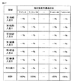
前記遊技機から出力された、遊技媒体の発射強度を示す信号(たとえば、発射強度を示す状態情報応答)と、遊技媒体が前記遊技領域に設けられた第1領域(たとえば普通入賞口272〜274、大入賞口271、始動入賞口275〜277、普通図柄ゲート、ステージ入口の少なくともいずれか1つを含む複数の領域のうちの1つの領域)を通過したことを示す信号(たとえば、通過領域を示す状態情報応答)と、遊技媒体が前記遊技領域に設けられた第2領域(たとえば普通入賞口272〜274、大入賞口271、始動入賞口275〜277、普通図柄ゲート、ステージ入口の少なくともいずれか1つを含む複数の領域のうちの1つの領域であって第1領域とは異なる領域)を通過したことを示す信号(たとえば、通過領域を示す状態情報応答)とを取得する取得手段(図42のS10)と、
前記取得手段が受信した信号を用いて、遊技媒体が前記第1領域を通過した回数および割合の少なくとも一方と遊技媒体が前記第2領域を通過した回数および割合の少なくとも一方とをそれぞれ前記発射強度別に集計する集計処理を行なう集計手段(たとえば図42のS13)とを備える。
(3-1) The present invention is an information management device (for example, CU3,
A signal (for example, a status information response indicating the launch intensity) output from the gaming machine and a first area where the game medium is provided in the game area (for example, normal winning
Using the signal received by the acquisition means, at least one of the number and ratio of game media passing through the first area and at least one of the number and ratio of game media passing through the second area are each determined as the firing strength. A totaling unit (for example, S13 in FIG. 42) that performs a totaling process for totaling is provided.
上記構成によれば、遊技媒体が第1領域を通過した回数および割合の少なくとも一方と遊技媒体が第2領域を通過した回数および割合の少なくとも一方とを発射強度別に集計する。そのため、発射強度に応じて遊技媒体がどの領域を通過する傾向にあるのか(発射強度に応じた各領域の通過し易さ)を把握することができる。なお、発射強度に応じた各領域の通過し易さを把握する際には、たとえば第1領域の通過回数と第2領域の通過割合とを比較するようにしてもよい。 According to the above configuration, at least one of the number and ratio of game media passing through the first area and at least one of the number and ratio of game media passing through the second area are tabulated for each firing strength. Therefore, it is possible to grasp which area the game medium tends to pass according to the launch intensity (ease of passing through each area according to the launch intensity). In addition, when grasping | ascertaining the ease of passage of each area | region according to discharge | release intensity | strength, you may make it compare the frequency | count of a 1st area | region and the passage ratio of a 2nd area, for example.
(3−2) 上記(3−1)の情報管理装置において、
前記第1領域は、遊技媒体が通過することによって所定の遊技制御(たとえば、遊技玉を払出す制御、封入循環式パチンコ機においては遊技玉数のデータを付与する制御、図柄の変動を開始する制御など)が行なわれる領域であり、
前記第2領域は、遊技媒体が通過することによって所定の遊技制御(たとえば、遊技玉を払出す制御、封入循環式パチンコ機においては遊技玉数のデータを付与する制御、図柄の変動を開始する制御など)が行なわれる領域であってかつ前記第1領域とは異なる領域である。
(3-2) In the information management apparatus of (3-1),
The first area starts a predetermined game control (for example, a control for paying out a game ball, a control for giving data on the number of game balls in an enclosed circulation pachinko machine, and a variation of a symbol when a game medium passes through the first area. Control, etc.)
The second area starts predetermined game control (for example, control for paying out a game ball, control for giving data on the number of game balls in an encircling pachinko machine, and variation in symbols when a game medium passes through. A region where control or the like is performed, and a region different from the first region.
上記構成によれば、所定の遊技制御が行なわれる複数の異なる領域が存在する場合において、発射強度に応じて遊技媒体がそれらの複数の領域のうちのどの領域を通過する傾向にあるのかを把握することができる。 According to the above configuration, when there are a plurality of different areas where predetermined game control is performed, it is determined which of the plurality of areas the game medium tends to pass according to the launch intensity. can do.
(3−3) 本発明は、遊技媒体を遊技領域へ発射して遊技を行なうことが可能な遊技機と通信可能な情報管理装置(たとえばCU3、ホールコン900、呼び出しランプ)であって、
前記遊技機から出力された、遊技媒体の発射強度を示す信号(たとえば、発射強度を示す状態情報応答)と、遊技媒体が前記遊技領域に設けられた第1領域(たとえば大入賞口271)を通過したことを示す信号(たとえば、通過領域を示す状態情報応答)と、遊技媒体が前記第1領域内に配置された第2領域(たとえば大入賞口271内の確変入賞口271a)を通過したことを示す信号(たとえば、通過領域を示す状態情報応答)とを取得する取得手段(たとえば図42のS10)と、
前記取得手段が受信した信号を用いて、遊技媒体が前記第1領域を通過した回数および割合の少なくとも一方と遊技媒体が前記第2領域を通過した回数および割合の少なくとも一方とをそれぞれ前記発射強度別に集計する集計処理を行なう集計手段(たとえば図42のS13)とを備える。
(3-3) The present invention is an information management device (for example, CU3,
A signal (for example, a status information response indicating the launch intensity) output from the gaming machine and indicating the launch intensity of the game medium, and a first area (eg, a prize winning opening 271) in which the game medium is provided in the game area. A signal indicating that it has passed (for example, a status information response indicating a passing area) and a game medium that has passed through a second area (for example, a probable
Using the signal received by the acquisition means, at least one of the number and ratio of game media passing through the first area and at least one of the number and ratio of game media passing through the second area are each determined as the firing strength. A totaling unit (for example, S13 in FIG. 42) that performs a totaling process for totaling is provided.
上記構成によれば、遊技媒体が第1領域を通過した回数および割合の少なくとも一方と遊技媒体が第1領域内に配置された第2領域を通過した回数および割合の少なくとも一方とを発射強度別に集計するので、どの発射強度であるときに遊技媒体が第1領域を通過しかつ第1領域内の第2領域を通過し易くなるのかを把握することができる。 According to the above configuration, at least one of the number and ratio of game media passing through the first area and at least one of the number and ratio of game media passing through the second area arranged in the first area are classified according to the firing strength. Since the counting is performed, it is possible to grasp at which launch strength the game medium passes through the first region and easily passes through the second region in the first region.
(3−4) 上記(3−3)の情報管理装置において、
前記第1領域は、遊技媒体が入賞し難いまたは入賞しない閉状態と遊技媒体が入賞可能な開状態とに変化可能な可変入賞領域(たとえば、大入賞口271)であり、
前記第2領域は、前記可変入賞領域内に配置され、遊技媒体が入賞することによって所定の遊技制御が行なわれる確率が向上する確率変動入賞口(たとえば、確変入賞口271a)である。
(3-4) In the information management apparatus of (3-3),
The first area is a variable winning area (for example, a big winning opening 271) that can be changed between a closed state in which a game medium is difficult to win or not winning and an open state in which a game medium can be won.
The second area is a probability-variation winning opening (for example, a probability changing winning
上記構成によれば、どの発射強度であるときに遊技媒体が可変入賞領域を通過しかつ可変入賞領域内に配置された確率変動入賞口を通過し易くなるのかを把握することができる。 According to the above configuration, it is possible to grasp at which launch strength the game medium passes through the variable winning area and easily passes through the probability variation winning opening arranged in the variable winning area.
(3−5) 上記(3−1)〜(3−4)のいずれかの情報管理装置において、
前記集計処理の結果を用いて、遊技媒体が前記第1領域を通過した回数および割合の少なくとも一方と遊技媒体が前記第2領域を通過した回数および割合の少なくとも一方とをそれぞれ前記発射強度別に表示可能な表示手段(たとえば図42のS16)をさらに備える。
(3-5) In the information management device according to any one of (3-1) to (3-4) above,
Using the result of the counting process, at least one of the number and ratio of game media passing through the first area and at least one of the number of games media passing through the second area and at least one of the ratio are displayed according to the firing strength. Possible display means (for example, S16 in FIG. 42) is further provided.
上記構成によれば、集計結果を表示することで、発射強度に応じて遊技媒体がどの領域を通過する傾向にあるのかを視覚的に把握することができる。 According to the above configuration, by displaying the total result, it is possible to visually grasp which region the game medium tends to pass according to the launch intensity.
(3−6) 上記(3−1)〜(3−5)のいずれかの情報管理装置において、
前記集計手段は、少なくとも前記発射強度が所定量(たとえば、発射強度がしきい値よりも低い値からしきい値に達する量)変化してから所定期間(たとえば、発射強度の変化中に発射された遊技媒体がすべて遊技領域を通過し終えると予測される期間)が経過するまでの期間(たとえば図44に示す期間α)は、前記集計処理を行なわない。
(3-6) In the information management device according to any one of (3-1) to (3-5) above,
The aggregating means is fired during a predetermined period (for example, during a change in the firing intensity) after at least the firing intensity has changed by a predetermined amount (for example, an amount by which the firing intensity reaches a threshold value from a value lower than the threshold value). The totaling process is not performed during a period (for example, a period α shown in FIG. 44) until a period when all the game media are predicted to finish passing through the game area.
上記構成によれば、少なくとも前記発射強度が所定量変化してから所定期間が経過するまでの期間は、遊技媒体の通過領域が不安定となると予測されるため、集計処理を行なわない。そのため、集計処理結果の信頼性が低下することを未然に防止できる。 According to the above configuration, at least during the period from when the firing intensity changes by a predetermined amount until the predetermined period elapses, the passing area of the game medium is predicted to be unstable, and thus the aggregation process is not performed. Therefore, it is possible to prevent the reliability of the totalization processing result from decreasing.
(3−7) 上記(3−1)〜(3−6)のいずれかの情報管理装置において、
前記遊技機の稼働直後(たとえば電源投入直後、遊技開始直後、発射強度が略零から増加し始めた直後)に前記遊技機から受信した発射強度を、当該発射強度を変化させるために前記遊技機に設けられた操作部の操作量が略零(たとえば、非操作時の値)であるときの初期発射強度として記憶し、前記初期発射強度を記憶した後に前記遊技機から受信した発射強度を前記初期発射強度で補正する補正手段(たとえば図43のフローチャート)をさらに備える。
(3-7) In the information management device according to any one of (3-1) to (3-6) above,
In order to change the launching intensity received from the gaming machine immediately after the gaming machine is operated (for example, immediately after turning on the power, immediately after starting the game, or immediately after the launching intensity starts increasing from substantially zero), the gaming machine Is stored as an initial launch intensity when the amount of operation of the operation unit provided in is approximately zero (for example, a value at the time of non-operation), and the launch intensity received from the gaming machine after storing the initial launch intensity Further provided is a correcting means (for example, the flowchart of FIG. 43) for correcting with the initial firing intensity.
上記構成によれば、たとえば操作部の遊びやガタ等により操作部の操作量と発射強度との間にばらつきが存在する場合であっても、発射強度を正確に検出することができる。 According to the above configuration, even when there is a variation between the operation amount of the operation unit and the emission intensity due to play or play of the operation unit, for example, the emission intensity can be accurately detected.
(3−8) 上記(3−1)〜(3−7)のいずれかの情報管理装置において、
前記情報管理装置は、前記発射強度が略零(たとえば、非操作時の値)よりも大きくかつ前記遊技媒体の発射数および回収数が変化しない場合に、前記遊技媒体の発射異常であると判定する判定手段(たとえば図49のフローチャート)をさらに備える。
(3-8) In the information management device according to any one of (3-1) to (3-7) above,
The information management device determines that the gaming medium is abnormally emitted when the firing strength is greater than approximately zero (for example, a value when not operated) and the number of games played and the number of collected games do not change. The determination means (for example, the flowchart of FIG. 49) to perform is further provided.
上記構成によれば、操作部の異常や遊技媒体が発射装置に供給されていないのに発射操作がされている状態(いわゆるカラ打ち)を検出することができる。 According to the above-described configuration, it is possible to detect an abnormality of the operation unit or a state in which a shooting operation is being performed even though no game medium is supplied to the launching device (so-called “coloring”).
(3−9) 上記(3−1)〜(3−8)のいずれかの情報管理装置において、
前記発射強度がしきい値以上であるか否か、または、しきい範囲(たとえば図51の発射強度しきい範囲)に含まれるか否かに応じて遊技媒体が打ち込まれた領域(たとえば右打ち領域、左打ち領域、ぶっ込み領域)を特定する特定手段(たとえば図50のフローチャート)と、
前記特定手段で用いられる前記しきい値または前記しきい範囲を変更可能な変更手段(たとえば図52のフローチャート)とをさらに備える。
(3-9) In the information management device according to any one of (3-1) to (3-8) above,
An area (for example, right-handed) in which a game medium is driven according to whether or not the firing strength is greater than or equal to a threshold value or whether or not it falls within a threshold range (for example, the firing strength threshold range in FIG. 51). Specifying means (for example, the flowchart of FIG. 50) for specifying the region, the left-handed region, the indentation region),
It further comprises a changing means (for example, the flowchart of FIG. 52) capable of changing the threshold value or the threshold range used by the specifying means.
上記構成によれば、発射強度を検出することで、遊技者がどの領域を狙って遊技媒体を打ち込もうとしているのかを特定することができる。 According to the above configuration, by detecting the firing strength, it is possible to specify which region the player is trying to drive in the game medium.
(3−10) 上記(3−1)〜(3−9)のいずれかの情報管理装置において、
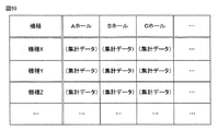
複数の遊技場にそれぞれ設置された複数の情報管理装置(たとえば図54のホールコン900)から前記集計処理の結果を取得可能な中央管理装置(たとえば図54の中央管理装置1000)との間で通信可能な通信手段(たとえば図54のS51)と、
自らが設置された遊技場とは別の遊技場に設置された遊技機の前記集計処理の結果を前記中央管理装置から取得して機種別に表示可能な機種別表示手段(たとえば図54のS52)とをさらに備える。
(3-10) In the information management device according to any one of (3-1) to (3-9) above,
Between a central management device (for example, the
Machine type display means (for example, S52 in FIG. 54) that can acquire the result of the totalization processing of the gaming machines installed in the game hall different from the game hall where the player is installed from the central management device and display them by model. And further comprising.
上記構成によれば、他の遊技場の機種別の集計結果を自らの遊技場で把握できるため、他の遊技場の遊技機の状態(たとえば釘調整の状態)を参考にして自らの遊技場の遊技機の状態を調整することができる。 According to the above configuration, since the result of counting the type of other game halls can be grasped at the own game hall, the game room of the other game hall is referred to, for example, the state of the nail adjustment. The state of the gaming machine can be adjusted.
(3−11) 上記(3−1)〜(3−10)のいずれかの情報管理装置において、
前記取得手段は、前記遊技機から出力された、各々を識別可能な複数の識別情報が変動表示していることを示す変動中信号をさらに取得し(たとえば図53のS40)、
前記変動中信号を受信していない状態で前記発射強度が略零から増加し始めた時点から、遊技媒体が前記第1領域を通過したことを示す信号または遊技媒体が前記第2領域を通過したことを示す信号を受信する時点までの時間を計測する計測手段(たとえば図53のS42、S44、S45)をさらに備える。
(3-11) In the information management device according to any one of (3-1) to (3-10),
The acquisition means further acquires a changing signal that is output from the gaming machine and indicates that a plurality of pieces of identification information that can be identified are variably displayed (eg, S40 in FIG. 53).
A signal indicating that a game medium has passed through the first area or a game medium has passed through the second area from the time when the firing intensity starts to increase from substantially zero while not receiving the changing signal. It further includes measuring means (for example, S42, S44, and S45 in FIG. 53) that measures the time until a signal indicating that the signal is received.
上記構成によれば、遊技者が遊技を始めてから、どの程度の時間で遊技媒体が第1領域または第2領域を通過する(たとえばパチンコ玉が入賞口に入賞する)のかを把握することができる。 According to the above configuration, it is possible to grasp how long the game medium passes through the first area or the second area (for example, a pachinko ball wins a winning opening) after the player starts playing. .
(4−1) 遊技者により遊技が行なわれる遊技機(P台2、S台2S)であって、
枠(外枠4と前枠5、本体枠2aS)と、
該枠に開閉可能に設けられた前面部材(ガラス扉6、前面扉2bS)と、
該前面部材の開放を検出する検出手段(ガラス扉開放検出スイッチ12、前枠開放検出スイッチ13、前面扉開放検出スイッチ)と、
前記枠に着脱自在に設けられた盤(遊技盤26、基板取付盤)と、
該盤と前記枠との電気的な接続を検出する盤接続検出手段(凸型ドロアコネクタ32、凹型ドロアコネクタ33)と、
該盤接続検出手段と前記開放検出手段とを直列に接続し、電源がオフとなっている期間である電源オフ期間にバックアップ電源により電力を供給するループ状に配線した電力線(ループ状の電力線500)と、
前記電源オフ期間に前記バックアップ電源により作動して前記開放検出手段による前記前面部材の開放の検出回数、および前記盤接続検出手段による前記盤と前記枠との電気的な切断の検出回数を計数する計数手段(図37のバックアップ電源により作動するCPU10aを含む計数カウンタ120)と、
該計数手段における前記電源オフ期間での計数値を計数結果として出力する出力手段(I/Oポート10d)とを備え、
前記計数手段は、予め定められた上限値まで計数した後再度初期値から計数を行なう循環式計数手段(図40(c))であり、
前記出力手段は、前記電源オフ期間での計数処理によって、計数値が前記電源オフの開始時点での計数値に戻ったときには、その旨を示す特定の値を前記計数結果として出力する(図36(b)に示す一周フラグが立つ値(=63)を出力する)。
(4-1) A gaming machine (
Frames (
A front member (
Detecting means for detecting the opening of the front member (glass door opening
A board (
Panel connection detection means (a
The panel connection detection means and the open detection means are connected in series, and a power line (loop-shaped power line 500) wired in a loop shape that supplies power from a backup power source during a power-off period, which is a period during which the power is off. )When,
It is operated by the backup power source during the power-off period and counts the number of detections of opening of the front member by the opening detection means and the number of detections of electrical disconnection between the panel and the frame by the panel connection detection means. Counting means (counting counter 120 including
Output means (I /
The counting means is a circulation type counting means (FIG. 40 (c)) for counting from the initial value again after counting up to a predetermined upper limit value.
When the count value returns to the count value at the start time of the power-off by the counting process in the power-off period, the output means outputs a specific value indicating that as the count result (FIG. 36). A value (= 63) in which the round flag shown in (b) is set is output).
このような構成によれば、前面部材の開放を検出するだけでなく、盤と枠との電気的な接続も検出することができ、予め定められた上限値まで計数した後再度初期値から計数を行なう循環式計数手段により前面部材の開放の検出回数、および盤接続検出手段による盤と枠との電気的な切断の検出回数を計数することにより、検出回数の計数値の記憶領域を過大にならないように抑えることができる。しかも、電源オフ期間での計数処理によって計数値が電源オフの開始時点での計数値に戻ったときには、その旨を示す特定の値が計数結果として出力されるために、循環式計数手段による計数値が一周してしまい検出回数が0回と判断されてしまう不都合も防止できる。また、仮に循環式計数手段による計数範囲が漏洩してその計数範囲に合わせて故意に計数手段の計数値を一周させるような開放動作および切断動作が行なわれたとしても、的確に開放の判断を行なうことができる。 According to such a configuration, not only the opening of the front member can be detected, but also the electrical connection between the panel and the frame can be detected. After counting up to a predetermined upper limit value, counting from the initial value is performed again. By counting the number of detections of opening of the front member by the circulation type counting means and the number of times of detecting electrical disconnection between the board and the frame by the board connection detecting means, the storage area of the count value of the number of detection times is excessive. It can be suppressed so that it does not become. In addition, when the count value returns to the count value at the start point of the power-off by the counting process in the power-off period, a specific value indicating that is output as the count result. The inconvenience that the numerical value goes around and the number of detection times is determined to be 0 can also be prevented. Also, even if an opening operation and a cutting operation are performed in which the counting range of the circulating counting means leaks and the count value of the counting means is intentionally made to circulate in accordance with the counting range, the determination of the opening is made accurately. Can be done.
(4−2) 上記(4−1)の遊技機において、
前記電力線(電力線500)は、前記枠と前記盤との間で信号を送受信する信号ケーブル(たとえば、図3に示す信号ケーブル36)内の配線に含まれる。
(4-2) In the gaming machine of (4-1) above,
The power line (power line 500) is included in a wiring in a signal cable (for example, the
このような構成によれば、盤から枠を外す際に、電力線を含む信号ケーブルを外す必要があるため、盤と枠との電気的な切断を必ず検出することができる。 According to such a configuration, when removing the frame from the board, it is necessary to remove the signal cable including the power line, so that electrical disconnection between the board and the frame can be detected without fail.
(4−3) 上記(4−2)の遊技機において、
前記盤接続検出手段は、前記信号ケーブルを接続する前記枠および前記盤に直接設けたフローティングコネクタ(凸型ドロアコネクタ32、凹型ドロアコネクタ33)である。
(4-3) In the gaming machine of (4-2) above,
The panel connection detection means is the frame for connecting the signal cable and a floating connector (
このような構成によれば、盤から枠を外す際に、電力線を含む信号ケーブルを外す必要があるため、盤と枠との電気的な切断を必ず検出することができる。さらに、盤を枠に取付ける際に、枠および盤に直接設けたフローティングコネクタの位置関係を意識することなくこれらが結合することができる。 According to such a configuration, when removing the frame from the board, it is necessary to remove the signal cable including the power line, so that electrical disconnection between the board and the frame can be detected without fail. Furthermore, when the board is attached to the frame, they can be coupled without being aware of the positional relationship between the frame and the floating connector provided directly on the board.
(4−4) 上記(4−1)〜(4−3)のいずれかの遊技機において、
前記盤の両面のうち、前記前面部材と対向する面とは反対側の面に遊技状態を制御する主制御手段が設けられ、
該主制御手段(主制御基板16、主制御部161)は、前記枠から前記盤を取外すことで、前記盤から着脱可能となる。
(4-4) In any one of the above gaming machines (4-1) to (4-3),
Of the two sides of the board, main control means for controlling the gaming state is provided on the side opposite to the side facing the front member,
The main control means (
このような構成によれば、主制御手段を盤から取外す際に、枠から盤を外す必要があるので、盤接続検出手段によって主制御手段を盤から取外す動作を検出することができる。 According to such a configuration, when removing the main control means from the board, it is necessary to remove the board from the frame. Therefore, the operation of removing the main control means from the board can be detected by the board connection detecting means.
(4−5) 上記(4−4)の遊技機において、
前記電力線は、前記盤と前記主制御手段との電気的な接続を検出する主制御接続検出手段(遊技盤26の電力線500と主制御基板16の電力線500aとの接続部分)をさらに直列に接続する(たとえば、主制御手段の電力線500aをループ状の電力線500の一部として構成する)。
(4-5) In the gaming machine (4-4) above,
The power line further connects in series a main control connection detecting means (a connecting portion between the
このような構成によれば、盤から主制御手段を取外す際に電力線を構成する配線が切断されることで、盤から主制御手段を取外したことを容易に検出することができる。 According to such a configuration, it is possible to easily detect that the main control means has been removed from the board by disconnecting the wiring constituting the power line when removing the main control means from the board.
(4−6) 上記(4−1)〜(4−5)のいずれかの遊技機において、
前記枠には、遊技媒体の払出しを制御する払出制御手段(払出制御基板17、払出制御部171)が設けられ、
前記電力線は、前記盤と前記払出制御手段との電気的な接続を検出する払出制御接続検出手段(盤と払出制御手段との接続部分)をさらに直列に接続する(たとえば、払出制御手段内にループ状の電力線500を配線する)。
(4-6) In any one of the above gaming machines (4-1) to (4-5),
The frame is provided with payout control means (
The power line further connects in series with a payout control connection detecting means (connection portion between the board and the payout control means) for detecting an electrical connection between the board and the payout control means (for example, within the payout control means). A loop-shaped
このような構成によれば、盤から払出制御手段を取外す際に電力線を構成する配線が切断されることで、盤から払出制御手段を取外したことを容易に検出することができる。 According to such a configuration, it is possible to easily detect that the payout control means has been removed from the board by cutting the wiring constituting the power line when removing the payout control means from the board.
(4−7) 上記(4−1)〜(4−6)のいずれかの遊技機において、
前記計数手段は、前記電源オフ期間以外の電源がオンとなっている期間も、前記検出手段による前記前面部材の開放の検出回数を計数し(図40(c))、
前記計数手段による現時点での計数値を記憶し、該記憶値が外部の操作によって初期化されることがない第1記憶領域(図39のRAM内イメージの9〜14)と、
前記計数手段による前記電源オフの開始時点での計数値を記憶する第2記憶領域(図39のRAM内イメージの3〜8)とをさらに備え、
前記出力手段は、
計数値が前記電源オフの開始時点での計数値に戻っていないときには、前記第1記憶領域と前記第2記憶領域との差分値を計数結果として出力し(図39の差分値000000〜111110を出力し)、
計数値が前記電源オフの開始時点での計数値に戻ったときには、前記差分値が取り得る範囲以外の値を前記特定の値として出力する(図39の111111を出力する)。
(4-7) In any one of the gaming machines (4-1) to (4-6) above,
The counting means counts the number of detections of opening of the front member by the detecting means during a period in which the power source other than the power off period is on (FIG. 40 (c)),
A first storage area (9 to 14 in the image in RAM of FIG. 39) in which the current count value by the counting means is stored, and the stored value is not initialized by an external operation;
A second storage area (3 to 8 in the image in RAM of FIG. 39) for storing a count value at the time when the power-off is started by the counting means;
The output means includes
When the count value does not return to the count value at the time when the power is turned off, the difference value between the first storage area and the second storage area is output as the count result (difference values 000000 to 111110 in FIG. 39 are output). Output),
When the count value returns to the count value at the time of starting the power-off, a value outside the range that the difference value can take is output as the specific value (111111 in FIG. 39 is output).
このような構成によれば、計数値が電源オフの開始時点での計数値に戻っていないときには、循環式計数手段による現時点での計数値と循環式計数手段による電源オフの開始時点での計数値との差分値が計数結果として出力されるために、電源オフの期間中における前面部材の開放の検出回数、および盤接続検出手段による盤と枠との電気的な切断の検出回数などが計数結果として出力されて把握することができる。一方、計数値が電源オフの開始時点での計数値に戻ったときには、前記差分値が採り得る範囲以外の値が特定の値として出力されるために、出力された値の差分値が採り得る範囲外の特定の値であるか否かを判断することにより循環式計数手段の計数値が一周したことを把握でき、開放および切断を的確に検出することができる。 According to such a configuration, when the count value does not return to the count value at the start time of power-off, the count value at the present time by the circulation type counting means and the count value at the start time of power-off by the circulation type counting means. Since the difference value from the numerical value is output as the counting result, the number of detections of opening of the front member during the power-off period and the number of detections of electrical disconnection between the panel and the frame by the panel connection detecting means are counted. It is output as a result and can be grasped. On the other hand, when the count value returns to the count value at the time when the power is turned off, a value other than the range that can be taken by the difference value is output as a specific value, so that the difference value of the output value can be taken. By judging whether or not the specific value is out of the range, it is possible to grasp that the count value of the circulation type counting means has made a full round, and it is possible to accurately detect the opening and the disconnection.
(4−8) 上記(4−7)の遊技機において、
電源断時に前記第2記憶領域の記憶値が前記第1記憶領域に記憶されるとともに、前記第1記憶領域の記憶値は所定条件の成立に基づいて初期化される(図40に示すS6において、記憶値を0にクリアする前に、その記憶値を現在値に上書き保存した後その記憶値を0にクリアするように制御してもよい)。
(4-8) In the gaming machine of (4-7) above,
The stored value in the second storage area is stored in the first storage area when the power is turned off, and the stored value in the first storage area is initialized when a predetermined condition is satisfied (in S6 shown in FIG. 40). Further, before clearing the stored value to 0, the stored value may be overwritten and saved to the current value, and then the stored value may be cleared to 0).
このような構成によれば、電源オフの開始時点での計数値を記憶する第2記憶領域の記憶値が第1記憶領域に記憶され、その第1記憶領域の記憶値が所定条件の成立に基づいて初期化されるために、第1記憶領域の記憶値が保持され続けることによる循環式計数手段の計数値に関する計数範囲等の情報が漏洩することを極力防止することができる。 According to such a configuration, the storage value of the second storage area that stores the count value at the start of power-off is stored in the first storage area, and the storage value of the first storage area satisfies the predetermined condition. Since it is initialized on the basis of this, it is possible to prevent leakage of information such as a count range related to the count value of the circulation type counting means by keeping the stored value in the first storage area as much as possible.
(4−9) 上記(4−1)〜(4−8)のいずれかの遊技機において、
前記前面部材は、一端を軸支されて回動可能に設けられ(図2)、
前記検出手段は、前記前面部材における前記軸支されている側とは逆の遊端側に設けられている(図2)。
(4-9) In any one of the above gaming machines (4-1) to (4-8),
The front member is pivotally supported at one end (FIG. 2),
The detection means is provided on the free end side of the front member opposite to the pivotally supported side (FIG. 2).
このような構成によれば、循環式計数手段が、前面部材における軸支されている側とは逆の遊端側に設けられているために、前面部材の開放に伴って移動距離が長い遊端側において検出でき、前面部材の開放の検出精度を上げることができる。 According to such a configuration, the circulation type counting means is provided on the free end side of the front member opposite to the shaft-supported side. It can be detected at the end side, and the detection accuracy of the opening of the front member can be increased.
(4−10) 上記(4−1)の遊技機において、
前記前面部材の開放を検出して計数する制御と異なる制御を行なう制御手段(払出制御基板17)をさらに備え、
前記出力手段は、電源投入時に前記制御手段へ計数結果を出力し(図40に示すS4でYESとなりS5で払出制御基板17へ出力)、
前記制御手段は、前記計数結果として前記特定の値(一周フラグが立つ値(=63))を受信したときに、異常状態を示す信号を遊技機外部へ出力する(図41に示すS14)。
(4-10) In the gaming machine of (4-1) above,
Control means (dispensing control board 17) for performing control different from control for detecting and counting the opening of the front member is further provided,
The output means outputs a counting result to the control means when power is turned on (YES in S4 shown in FIG. 40 and output to the
The control means outputs a signal indicating an abnormal state to the outside of the gaming machine when receiving the specific value (the value (= 63) where the round flag is raised) as the counting result (S14 shown in FIG. 41).
このような構成によれば、電源投入時に計数結果が制御手段に出力されてその制御手段が計数結果として前記特定の値を受信したときに異常状態を示す信号が遊技機外部へ出力されるために、不正対策の強化を行なうことが可能となる。 According to such a configuration, when the power is turned on, the counting result is output to the control means, and when the control means receives the specific value as the counting result, a signal indicating an abnormal state is output to the outside of the gaming machine. In addition, fraud countermeasures can be strengthened.
(5−1) 本発明は、遊技機(P台2、S台2S)と、前記遊技機での遊技を可能にする遊技用装置(CU3)とを備える遊技用システムであって、
前記遊技用装置は、
前記遊技機による所定の動作(遊技玉の加算動作)を要求する動作要求電文(遊技玉加算要求ONの状態情報要求)を送信するか当該動作要求電文以外の電文を送信するかで異なる更新情報(加算通番:遊技玉加算要求ONのときには元の加算通番に+1したもの、遊技玉加算要求OFFのときには元の加算通番)を含む電文を送信する電文送信手段(図10、図11、図29、図30参照)と、
前記動作要求電文の送信後に電文を受信したときに、受信電文に含まれる更新情報が前記動作要求電文に含めて送信した更新情報を所定情報で更新して得られる情報と一致する場合には要求承諾と判定し、不一致の場合には要求承諾以外と判定する電文判定手段(図29:要求通番がm+2であれば要求承諾、m+1であれば要求拒否と判定)とを含み、
前記遊技機は、
前記動作要求電文を受信したときに、要求を承諾する場合には承諾電文を送信し、要求を拒否する場合には拒否電文を送信する応答電文送信手段(図10、図11、図29、図30参照)を含み、
前記応答電文送信手段は、
前記動作要求電文に含まれて送信されてきた更新情報を所定情報で更新して得られた情報を、前記承諾電文の更新情報として送信し(図29:要求承諾であればm+2を送信し、要求拒否であればm+1を送信)、
前記動作要求電文に含まれて送信されてきた更新情報を所定情報で更新せずに前記拒否電文の更新情報として送信する(図10、図11、図29、図30参照)。
(5-1) The present invention is a gaming system comprising a gaming machine (
The gaming device is:
Update information that differs depending on whether an operation request message (a game ball addition request ON state information request) requesting a predetermined operation (game ball addition operation) by the gaming machine is transmitted or a message other than the operation request message is transmitted A message transmission means for transmitting a message including (additional serial number: one added to the original addition serial number when the game ball addition request is ON, and the original addition serial number when the game ball addition request is OFF) (FIGS. 10, 11, and 29) , See FIG. 30),
When a message is received after transmission of the operation request message, a request is made if the update information included in the received message matches the information obtained by updating the update information transmitted in the operation request message with predetermined information. A message determination unit that determines that the request is accepted, and determines that the request is not accepted if it does not match (FIG. 29: request accepted if the request serial number is m + 2, and request reject if m + 1),
The gaming machine is
When the operation request message is received, a response message transmitting means for transmitting an acceptance message if the request is accepted, and transmitting a rejection message if the request is rejected (FIG. 10, FIG. 11, FIG. 29, FIG. 30)
The response message transmission means includes:
Information obtained by updating the update information contained in the operation request message and transmitted with predetermined information is transmitted as update information of the consent message (FIG. 29: If request is accepted, m + 2 is transmitted, M + 1 is sent if the request is rejected)
The update information transmitted in the operation request message is transmitted as update information of the reject message without updating with the predetermined information (see FIGS. 10, 11, 29, and 30).
このような構成によれば、動作要求電文の送信後に受信した電文の更新情報を参照することによって、動作要求電文が到達しているか否かを判定できるばかりでなく、返信されてきた電文が動作要求電文に対する承諾電文であるのか拒否電文であるのかまでを判定できる。 According to such a configuration, it is possible not only to determine whether or not the operation request message has arrived by referring to the update information of the message received after the operation request message has been transmitted, but the returned message is operated. It is possible to determine whether the request message is an acceptance message or a rejection message.
(5−2) 本発明は、遊技機(P台2、S台2S)での遊技を可能にするための遊技制御装置(CU3(またはCU3内のCU制御部))であって、
前記遊技機による所定の動作(遊技玉の加算動作)を要求する動作要求電文(遊技玉加算要求ONの状態情報要求)を送信するか当該動作要求電文以外の電文を送信するかで異なる更新情報(加算通番:遊技玉加算要求ONのときには元の加算通番に+1したもの、遊技玉加算要求OFFのときには元の加算通番)を含む電文を送信する電文送信手段(図10、図11、図29、図30参照)と、
前記動作要求電文の送信後に電文を受信したときに、受信電文に含まれる更新情報が前記動作要求電文に含めて送信した更新情報を所定情報で更新して得られる情報と一致する場合には要求承諾と判定し、不一致の場合には要求承諾以外と判定する電文判定手段(図29:要求通番がm+2であれば要求承諾、m+1であれば要求拒否と判定)とを含む。
(5-2) The present invention is a game control device (CU3 (or CU control unit in CU3)) for enabling a game on a gaming machine (
Update information that differs depending on whether an operation request message (a game ball addition request ON state information request) requesting a predetermined operation (game ball addition operation) by the gaming machine is transmitted or a message other than the operation request message is transmitted A message transmission means for transmitting a message including (additional serial number: one added to the original addition serial number when the game ball addition request is ON, and the original addition serial number when the game ball addition request is OFF) (FIGS. 10, 11, and 29) , See FIG. 30),
When a message is received after transmission of the operation request message, a request is made if the update information included in the received message matches the information obtained by updating the update information transmitted in the operation request message with predetermined information. A message determination means for determining that the request is approved and determining that the request is not approved in the case of disagreement (FIG. 29: request approval if the request serial number is m + 2 and request reject if m + 1) is included.
このような構成によれば、動作要求電文の送信後に受信した電文の更新情報を参照することによって、動作要求電文が到達しているか否かを判定できるばかりでなく、返信されてきた電文が動作要求電文に対する承諾電文であるのか拒否電文であるのかまでを判定できる。 According to such a configuration, it is possible not only to determine whether or not the operation request message has arrived by referring to the update information of the message received after the operation request message has been transmitted, but the returned message is operated. It is possible to determine whether the request message is an acceptance message or a rejection message.
(5−3) 本発明は、遊技を可能にするための遊技制御装置(P台2、S台2S(またはCU3内のセキュリティチップ))であって、
前記遊技機による所定の動作(遊技玉の加算動作)を要求する動作要求電文(遊技玉加算要求ONの状態情報要求)を受信したときに、要求を承諾する場合には承諾電文を送信し、要求を拒否する場合には拒否電文を送信する応答電文送信手段(図10、図11、図29、図30参照)を含み、
前記応答電文送信手段は、
前記動作要求電文に含まれて送信されてきた更新情報を所定情報(+1)で更新して得られた情報を、前記承諾電文の更新情報として送信し(たとえば、図29では、受信したm+1の加算通番に対してm+2を返信)、
前記動作要求電文に含まれて送信されてきた更新情報を所定情報で更新せずに前記拒否電文の更新情報として送信する(図29参照)。
(5-3) The present invention is a game control device (
When an operation request message requesting a predetermined operation (game ball addition operation) by the gaming machine is received (a game ball addition request ON state information request), an approval message is transmitted if the request is accepted, In the case of refusing a request, it includes response message transmission means (see FIGS. 10, 11, 29, and 30) for transmitting a rejection message,
The response message transmission means includes:
Information obtained by updating the update information contained in the operation request message and transmitted with predetermined information (+1) is transmitted as update information of the consent message (for example, in FIG. 29, the received m + 1 Reply m + 2 to the additional serial number)
The update information included and transmitted in the operation request message is transmitted as update information of the reject message without updating with predetermined information (see FIG. 29).
このような構成によれば、動作要求電文に対する応答電文に含める更新情報を相手方に参照させることによって、動作要求電文が到達しているか否かを判定させることができるばかりでなく、返信した電文が動作要求電文に対する承諾電文であるのか拒否電文であるのかまでを判定させることができる。 According to such a configuration, it is possible not only to determine whether or not the operation request message has arrived by referring to the update information to be included in the response message to the operation request message, but also to return the message that has been returned. It is possible to determine whether the message is an acceptance message or a rejection message for the operation request message.
(5−4) 上記(5−1)の遊技用システム、または上記(5−2)の遊技制御装置において、
前記電文送信手段は、前記動作要求電文を送信するときには、直前に受信した電文に含まれる更新情報を所定情報で更新して得られる情報を送信電文の更新情報として送信し、前記動作要求電文以外の電文を送信するときには、直前に受信した電文に含まれる更新情報を送信電文の更新情報として送信する(図29、図30参照)。
(5-4) In the game system of (5-1) or the game control device of (5-2),
When transmitting the operation request message, the message transmission means transmits information obtained by updating the update information included in the message received immediately before with the predetermined information as update information of the transmission message, and other than the operation request message Is transmitted as update information of the transmitted message (see FIGS. 29 and 30).
このような構成によれば、通信の相手方は、受け取った更新情報が、直前に送信した電文に含まれる更新情報を所定情報で更新して得られたものであれば動作要求電文であると判定できる。 According to such a configuration, the communication partner determines that it is an operation request message if the received update information is obtained by updating the update information included in the message transmitted immediately before with the predetermined information. it can.
(5−5) 上記(5−1)または(5−4)に記載の遊技用システムであって、前記電文送信手段および前記応答電文送信手段は、電文の送信順を特定可能な送信順情報(通常通番)を前記更新情報と別に各電文に含めて送信する(図29、図30参照)。 (5-5) The gaming system according to (5-1) or (5-4) above, wherein the message transmission unit and the response message transmission unit are capable of specifying a transmission order of messages. (Normal serial number) is included in each message separately from the update information and transmitted (see FIGS. 29 and 30).
このような構成によれば、動作要求電文に関わる通信以外においても、電文の到達確認を行なうことが可能となる。 According to such a configuration, it is possible to confirm the arrival of a message other than the communication related to the operation request message.
(5−6) 上記(5−5)に記載の遊技用システムであって、前記電文送信手段および前記応答電文送信手段は、前記更新情報を更新して電文を送信するときには前記送信順情報を更新しない(図30参照)。 (5-6) In the gaming system according to (5-5), the message transmission unit and the response message transmission unit update the update information and transmit the message when the update information is transmitted. It is not updated (see FIG. 30).
このような構成によれば、更新情報を更新して電文を送信するときにも前記送信順情報を更新する場合に比較して、送信順情報の更新に関する制御負担を軽減できる。 According to such a configuration, it is possible to reduce the control burden related to the update of the transmission order information as compared with the case where the transmission order information is updated even when the update information is updated and a message is transmitted.
(5−7) 上記(5−1)(5−4)〜(5−6)のいずれかに記載の遊技用システムであって、前記電文判定手段は、
前記動作要求電文の送信後に電文を受信したときに、受信電文に含まれる更新情報が前記動作要求電文に含めて送信した更新情報と一致する場合には要求拒否と判定し(図29、図30参照)、
前記動作要求電文の送信後に電文を受信したときに、受信電文に含まれる更新情報が前記動作要求電文に含めて送信した更新情報を前記所定情報で更新して得られる情報と一致せず、前記動作要求電文に含めて送信した更新情報とも一致しない場合には、前記動作要求電文の未到達と判定する(図29、図30参照)。
(5-7) The gaming system according to any one of (5-1) (5-4) to (5-6), wherein the message determination unit includes:
When a message is received after the operation request message is transmitted, if the update information included in the received message matches the update information included in the operation request message and transmitted, it is determined that the request is rejected (FIGS. 29 and 30). reference),
When a message is received after transmission of the operation request message, the update information included in the received message does not match the information obtained by updating the update information transmitted in the operation request message with the predetermined information, If the update information included in the operation request message and transmitted does not match, it is determined that the operation request message has not been reached (see FIGS. 29 and 30).
(5−8) 本発明は、遊技機(P台2、S台2S)と、前記遊技機での遊技を可能にする遊技用装置(CU3)とを備える遊技用システムであって、
前記遊技用装置は、
前記遊技機による所定の動作(遊技玉の加算動作)を要求する動作要求電文(遊技玉加算要求ONの状態情報要求)を送信するか当該動作要求電文以外の電文を送信するかで異なる更新情報(加算通番:遊技玉加算要求ONのときには元の加算通番に+1したもの、遊技玉加算要求OFFのときには元の加算通番)を含む電文を送信する電文送信手段(図10、図11、図25、図29、図30参照)と、
前記動作要求電文の送信後に電文を受信したときに、受信電文に含まれる更新情報が前記動作要求電文に含めて送信した更新情報と所定の関係にある情報と一致する場合には要求承諾と判定し、不一致の場合には要求承諾以外と判定する電文判定手段(図25:加算通番がm+1であれば要求承諾、mであれば要求拒否と判定、図29:要求通番がm+2であれば要求承諾、m+1であれば要求拒否と判定)とを含み、
前記遊技機は、
前記動作要求電文を受信したときに、要求を承諾する場合には承諾電文を送信し、要求を拒否する場合には拒否電文を送信する応答電文送信手段(図10、図11、図25、図29、図30参照)を含み、
前記応答電文送信手段は、
前記動作要求電文に含まれて送信されてきた更新情報と所定の関係にある情報を、前記承諾電文の更新情報として送信し(図25:要求承諾であればm+1を送信し、要求拒否であればmを送信、図29:要求承諾であればm+2を送信し、要求拒否であればm+1を送信)、
前記動作要求電文に含まれて送信されてきた更新情報と所定の関係にある情報を、前記拒否電文の更新情報として送信する(図10、図11、図25、図29、図30参照)。
(5-8) The present invention is a gaming system comprising a gaming machine (
The gaming device is:
Update information that differs depending on whether an operation request message (a game ball addition request ON state information request) requesting a predetermined operation (game ball addition operation) by the gaming machine is transmitted or a message other than the operation request message is transmitted A message transmission means for transmitting a message including (additional serial number: one added to the original addition serial number when the game ball addition request is ON, or the original addition serial number when the game ball addition request is OFF) (FIGS. 10, 11, 25) , FIG. 29 and FIG. 30),
When the message is received after the operation request message is transmitted, if the update information included in the received message matches the update information included in the operation request message and transmitted, it is determined that the request is accepted. If there is a mismatch, a message determination means for determining that the request is not approved (FIG. 25: If the added serial number is m + 1, the request is accepted; if m, the request is rejected; Acceptance, if m + 1, the request is rejected)
The gaming machine is
When the operation request message is received, a response message transmitting means for transmitting an acceptance message if the request is accepted and transmitting a rejection message if the request is rejected (FIGS. 10, 11, 25, and 25). 29, see FIG. 30)
The response message transmission means includes:
Update information included in the operation request message and transmitted in a predetermined relationship is transmitted as update information of the acceptance message (FIG. 25: If the request is accepted, m + 1 is transmitted, and the request is rejected. M is transmitted if the request is accepted, m + 2 is transmitted if the request is accepted, and m + 1 is transmitted if the request is rejected).
Information having a predetermined relationship with the update information included in the operation request message and transmitted is transmitted as update information of the reject message (see FIGS. 10, 11, 25, 29, and 30).
このような構成によれば、動作要求電文の送信後に受信した電文の更新情報を参照することによって、動作要求電文が到達しているか否かを判定できるばかりでなく、返信されてきた電文が動作要求電文に対する承諾電文であるのか拒否電文であるのかまでを判定できる。 According to such a configuration, it is possible not only to determine whether or not the operation request message has arrived by referring to the update information of the message received after the operation request message has been transmitted, but the returned message is operated. It is possible to determine whether the request message is an acceptance message or a rejection message.
(5−9) 本発明は、遊技機(P台2、S台2S)での遊技を可能にするための遊技制御装置(CU3(またはCU3内のCU制御部))であって、
前記遊技機による所定の動作(遊技玉の加算動作)を要求する動作要求電文(遊技玉加算要求ONの状態情報要求)を送信するか当該動作要求電文以外の電文を送信するかで異なる更新情報(加算通番:遊技玉加算要求ONのときには元の加算通番に+1したもの、遊技玉加算要求OFFのときには元の加算通番)を含む電文を送信する電文送信手段(図10、図11、図25、図29、図30参照)と、
前記動作要求電文の送信後に電文を受信したときに、受信電文に含まれる更新情報が前記動作要求電文に含めて送信した更新情報と所定の関係にある情報と一致する場合には要求承諾と判定し、不一致の場合には要求承諾以外と判定する電文判定手段(図25:加算通番がm+1であれば要求承諾、mであれば要求拒否と判定、図29:要求通番がm+2であれば要求承諾、m+1であれば要求拒否と判定)とを含む。
(5-9) The present invention is a game control device (CU3 (or CU control unit in CU3)) for enabling a game on a gaming machine (
Update information that differs depending on whether an operation request message (a game ball addition request ON state information request) requesting a predetermined operation (game ball addition operation) by the gaming machine is transmitted or a message other than the operation request message is transmitted A message transmission means for transmitting a message including (additional serial number: one added to the original addition serial number when the game ball addition request is ON, or the original addition serial number when the game ball addition request is OFF) (FIGS. 10, 11, 25) , FIG. 29 and FIG. 30),
When the message is received after the operation request message is transmitted, if the update information included in the received message matches the update information included in the operation request message and transmitted, it is determined that the request is accepted. If there is a mismatch, a message determination means for determining that the request is not approved (FIG. 25: If the added serial number is m + 1, the request is accepted; if m, the request is rejected; FIG. 29: If the request serial number is m + 2, the request is requested. Acceptance, if m + 1, the request is rejected).
このような構成によれば、動作要求電文の送信後に受信した電文の更新情報を参照することによって、動作要求電文が到達しているか否かを判定できるばかりでなく、返信されてきた電文が動作要求電文に対する承諾電文であるのか拒否電文であるのかまでを判定できる。 According to such a configuration, it is possible not only to determine whether or not the operation request message has arrived by referring to the update information of the message received after the operation request message has been transmitted, but the returned message is operated. It is possible to determine whether the request message is an acceptance message or a rejection message.
(5−10) 本発明は、遊技を可能にするための遊技制御装置(P台2、S台2S(またはCU3内のセキュリティチップ))であって、
前記遊技機による所定の動作(遊技玉の加算動作)を要求する動作要求電文(遊技玉加算要求ONの状態情報要求)を受信したときに、要求を承諾する場合には承諾電文を送信し、要求を拒否する場合には拒否電文を送信する応答電文送信手段(図10、図11、図25、図29、図30参照)を含み、
前記応答電文送信手段は、
前記動作要求電文に含まれて送信されてきた更新情報と所定の関係にある情報を、前記承諾電文の更新情報として送信し(たとえば、図25:受信したm+1の加算通番に対して、m+1を返信、図29では、受信したm+1の加算通番に対してm+2を返信)、
前記動作要求電文に含まれて送信されてきた更新情報と所定の関係にある情報を、前記拒否電文の更新情報として送信する(図25、図29参照)。
(5-10) The present invention is a game control device (
When an operation request message requesting a predetermined operation (game ball addition operation) by the gaming machine is received (a game ball addition request ON state information request), an approval message is transmitted if the request is accepted, In the case of refusing a request, it includes response message transmission means (see FIGS. 10, 11, 25, 29, and 30) for transmitting a rejection message.
The response message transmission means includes:
Update information included in the operation request message and transmitted in a predetermined relationship is transmitted as update information of the acceptance message (for example, FIG. 25: m + 1 is added to the received m + 1 addition serial number). Reply, in FIG. 29, m + 2 is replied to the added serial number of m + 1 received)
Information having a predetermined relationship with the update information transmitted in the operation request message is transmitted as update information of the reject message (see FIGS. 25 and 29).
このような構成によれば、動作要求電文に対する応答電文に含める更新情報を相手方に参照させることによって、動作要求電文が到達しているか否かを判定させることができるばかりでなく、返信した電文が動作要求電文に対する承諾電文であるのか拒否電文であるのかまでを判定させることができる。 According to such a configuration, it is possible not only to determine whether or not the operation request message has arrived by referring to the update information to be included in the response message to the operation request message, but also to return the message that has been returned. It is possible to determine whether the message is an acceptance message or a rejection message for the operation request message.
(5−11) 本発明は、遊技機(P台2、S台2S)と、前記遊技機での遊技を可能にする遊技用装置(CU3)とを備える遊技用システムであって、
前記遊技用装置は、
前記遊技機による所定の動作(遊技玉の加算動作)を要求する動作要求電文(遊技玉加算要求ONの状態情報要求)を送信するか当該動作要求電文以外の電文を送信するかで異なる更新情報(加算通番:遊技玉加算要求ONのときには元の加算通番に+1したもの、遊技玉加算要求OFFのときには元の加算通番)を含む電文を送信する電文送信手段(図10、図11、図25参照)と、
前記動作要求電文の送信後に電文を受信したときに、受信電文に含まれる更新情報が前記動作要求電文に含めて送信した更新情報と一致する場合には要求承諾と判定し、不一致の場合には要求承諾以外と判定する電文判定手段(図25:加算通番がm+1であれば要求承諾、mであれば要求拒否と判定)とを含み、
前記遊技機は、
前記動作要求電文を受信したときに、要求を承諾する場合には承諾電文を送信し、要求を拒否する場合には拒否電文を送信する応答電文送信手段(図10、図11、図25参照)を含み、
前記応答電文送信手段は、
前記動作要求電文に含まれて送信されてきた更新情報を、前記承諾電文の更新情報として送信し(図25:要求承諾であればm+1を送信し、要求拒否であればmを送信)、
前記動作要求電文に含まれて送信されてきた更新情報の前回の更新情報を、前記拒否電文の更新情報として送信する(図10、図11、図25、図29、図30参照)。
(5-11) The present invention is a gaming system comprising a gaming machine (
The gaming device is:
Update information that differs depending on whether an operation request message (a game ball addition request ON state information request) requesting a predetermined operation (game ball addition operation) by the gaming machine is transmitted or a message other than the operation request message is transmitted A message transmission means for transmitting a message including (additional serial number: one added to the original addition serial number when the game ball addition request is ON, and the original addition serial number when the game ball addition request is OFF) See)
When a message is received after transmission of the operation request message, if the update information included in the received message matches the update information included in the operation request message and transmitted, it is determined as request acceptance, and in the case of a mismatch A message determination means for determining that the request is not approved (FIG. 25: request approval if the addition serial number is m + 1, and request rejection if m is added),
The gaming machine is
When the operation request message is received, a response message transmission means for transmitting an acceptance message if the request is accepted and transmitting a rejection message if the request is rejected (see FIGS. 10, 11, and 25). Including
The response message transmission means includes:
Update information transmitted in the operation request message is transmitted as update information of the acceptance message (FIG. 25: m + 1 is transmitted if the request is accepted, m is transmitted if the request is rejected),
The previous update information of the update information transmitted in the operation request message is transmitted as update information of the reject message (see FIGS. 10, 11, 25, 29, and 30).
このような構成によれば、動作要求電文の送信後に受信した電文の更新情報を参照することによって、動作要求電文が到達しているか否かを判定できるばかりでなく、返信されてきた電文が動作要求電文に対する承諾電文であるのか拒否電文であるのかまでを判定できる。 According to such a configuration, it is possible not only to determine whether or not the operation request message has arrived by referring to the update information of the message received after the operation request message has been transmitted, but the returned message is operated. It is possible to determine whether the request message is an acceptance message or a rejection message.
(5−12) 本発明は、遊技機(P台2、S台2S)での遊技を可能にするための遊技制御装置(CU3(またはCU3内のCU制御部))であって、
前記遊技機による所定の動作(遊技玉の加算動作)を要求する動作要求電文(遊技玉加算要求ONの状態情報要求)を送信するか当該動作要求電文以外の電文を送信するかで異なる更新情報(加算通番:遊技玉加算要求ONのときには元の加算通番に+1したもの、遊技玉加算要求OFFのときには元の加算通番)を含む電文を送信する電文送信手段(図10、図11、図25参照)と、
前記動作要求電文の送信後に電文を受信したときに、受信電文に含まれる更新情報が前記動作要求電文に含めて送信した更新情報と一致する場合には要求承諾と判定し、不一致の場合には要求承諾以外と判定する電文判定手段(図25:加算通番がm+1であれば要求承諾、mであれば要求拒否と判定)とを含む。
(5-12) The present invention is a game control device (CU3 (or CU control unit in CU3)) for enabling a game on a gaming machine (
Update information that differs depending on whether an operation request message (a game ball addition request ON state information request) requesting a predetermined operation (game ball addition operation) by the gaming machine is transmitted or a message other than the operation request message is transmitted A message transmission means for transmitting a message including (additional serial number: one added to the original addition serial number when the game ball addition request is ON, and the original addition serial number when the game ball addition request is OFF) See)
When a message is received after transmission of the operation request message, if the update information included in the received message matches the update information included in the operation request message and transmitted, it is determined as request acceptance, and in the case of a mismatch A message determination means for determining that the request is not approved (FIG. 25: If the additional serial number is m + 1, the request is approved, and if m, the request is rejected).
このような構成によれば、動作要求電文の送信後に受信した電文の更新情報を参照することによって、動作要求電文が到達しているか否かを判定できるばかりでなく、返信されてきた電文が動作要求電文に対する承諾電文であるのか拒否電文であるのかまでを判定できる。 According to such a configuration, it is possible not only to determine whether or not the operation request message has arrived by referring to the update information of the message received after the operation request message has been transmitted, but the returned message is operated. It is possible to determine whether the request message is an acceptance message or a rejection message.
(5−13) 本発明は、遊技を可能にするための遊技制御装置(P台2、S台2S(またはCU3内のセキュリティチップ))であって、
前記遊技機による所定の動作(遊技玉の加算動作)を要求する動作要求電文(遊技玉加算要求ONの状態情報要求)を受信したときに、要求を承諾する場合には承諾電文を送信し、要求を拒否する場合には拒否電文を送信する応答電文送信手段(図10、図11、図25)を含み、
前記応答電文送信手段は、
前記動作要求電文に含まれて送信されてきた更新情報を、前記承諾電文の更新情報として送信し(たとえば、図25:受信したm+1の加算通番に対して、m+1を返信)、
前記動作要求電文に含まれて送信されてきた更新情報の前回の更新情報を、前記拒否電文の更新情報として送信する(図25参照)。
(5-13) The present invention is a game control device (
When an operation request message requesting a predetermined operation (game ball addition operation) by the gaming machine is received (a game ball addition request ON state information request), an approval message is transmitted if the request is accepted, In the case of refusing a request, it includes response message transmission means (FIGS. 10, 11, and 25) for transmitting a rejection message,
The response message transmission means includes:
The update information transmitted in the operation request message is transmitted as the update information of the acceptance message (for example, FIG. 25: m + 1 is returned to the added m + 1 serial number received),
The previous update information of the update information transmitted in the operation request message is transmitted as update information of the reject message (see FIG. 25).
このような構成によれば、動作要求電文に対する応答電文に含める更新情報を相手方に参照させることによって、動作要求電文が到達しているか否かを判定させることができるばかりでなく、返信した電文が動作要求電文に対する承諾電文であるのか拒否電文であるのかまでを判定させることができる。 According to such a configuration, it is possible not only to determine whether or not the operation request message has arrived by referring to the update information to be included in the response message to the operation request message, but also to return the message that has been returned. It is possible to determine whether the message is an acceptance message or a rejection message for the operation request message.
このような構成によれば、更新情報に基づいて要求承諾であるか否かのみならず、要求拒否であるか、そもそも操作要求電文が到達していないのかまでを判定可能となる。 According to such a configuration, it is possible to determine not only whether the request is accepted based on the update information, but also whether the request is rejected or whether the operation request message has not arrived in the first place.
以下、図面を参照して本発明に係る実施の形態を以下に説明する。
<パチンコ機の構成>
まず、図1を参照して、本実施の形態に係るパチンコ機の構成を説明する。遊技場(ホール)内に複数配置されている各遊技島(図示略)には、遊技機の一例の封入循環式パチンコ機(以下、遊技機、パチンコ機またはP台と略称することもある)2が併設されている。なお、P台2の所定側の側方位置には、該P台2に対して遊技用装置の一例のカードユニット(以下CUと略称することもある)3が1対1に対応設置されている。
Embodiments according to the present invention will be described below with reference to the drawings.
<Configuration of pachinko machine>
First, the configuration of the pachinko machine according to the present embodiment will be described with reference to FIG. In each amusement island (not shown) arranged in a plurality of game halls (halls), an enclosed circulation pachinko machine as an example of a game machine (hereinafter also abbreviated as a game machine, a pachinko machine, or a P machine). 2 is attached. A card unit (which may be abbreviated as CU hereinafter) 3 as an example of a gaming device is installed in a one-to-one correspondence with the P table 2 at a side position on the predetermined side of the P table 2. Yes.
P台2は、内部に遊技媒体の一例のパチンコ玉を封入しており、遊技者が打球操作ハンドル25を操作することにより、発射モータ18(図4参照)を駆動させて封入玉を1発ずつ遊技盤26前面の遊技領域27に打込んで遊技ができるように構成されている。具体的には、打球操作ハンドル25の周囲にタッチセンサが設けられており、遊技者が打球操作ハンドル25を操作している状態でその遊技者の手がタッチセンサに触れ、その遊技者の手の接触をタッチセンサで検知して発射モータ18が駆動される。この状態で、遊技者による打球操作ハンドル25の回動操作量に応じて打球発射勢いが調整されて玉が遊技領域27内に発射される。
The P stand 2 encloses a pachinko ball as an example of a game medium inside, and when the player operates the hitting
パチンコ玉の発射強度(以下、単に発射強度Tともいう)は、打球操作ハンドル25の回動操作量(以下、単にハンドル操作量ともいう)に応じて調整可能であり、ハンドル操作量を大きくするにしたがって発射強度Tが大きくなる。したがって、遊技者は、ハンドル操作量を調節することによって、自らが狙う領域をパチンコ玉が通過するように発射強度Tを調整することができる。 The firing strength of the pachinko ball (hereinafter simply referred to as the firing strength T) can be adjusted in accordance with the amount of rotation of the hitting ball operating handle 25 (hereinafter also simply referred to as the handle operating amount), and the handle operating amount is increased. The firing intensity T increases accordingly. Therefore, the player can adjust the firing strength T so that the pachinko ball passes through the region he / she aims by adjusting the handle operation amount.
図1に示すP台2は、いわゆる第1種のパチンコ機であって、遊技領域27の中央に可変表示装置(特別図柄とも言う)278が設けられている。また、遊技領域27には、打込まれたパチンコ玉が入賞可能な複数種類の入賞口が設けられている。図1に示す遊技領域27には、1つの大入賞口(可変入賞球装置)271と、3つの普通入賞口272,273,274と、3つの始動入賞口275,276,277とが示されている。特に、始動入賞口276は、遊技者にとって有利な第1の状態(たとえば開成状態)と遊技者にとって不利な第2の状態(たとえば閉成状態)とに変化可能な電動チューリップで構成されている。
The P stand 2 shown in FIG. 1 is a so-called first type pachinko machine, and a variable display device (also referred to as a special symbol) 278 is provided in the center of the
可変表示装置278は、複数種類の識別情報(図柄)を可変表示可能な可変表示部を備えており、各始動入賞口275,276,277に入賞した始動入賞玉の検出信号に基づいてそれらの複数種類の識別情報の可変表示を開始させる。可変表示装置の表示結果が特定の識別情報の組合せ(たとえばぞろ目)になると、大当り状態となり、大入賞口271が開放する。
The
大入賞口271内には、確変入賞口271aが配置される。大入賞口271に入賞したパチンコ玉がさらに確変入賞口271aにも入賞すると、現在の大当り状態の終了後に大当りが発生する確率が向上する状態(以下、確率変動状態、あるいは単に確変状態ともいう)が発生する。
A probable winning prize opening 271 a is arranged in the big
また、可変表示装置278の表示結果が大当り図柄の組合せ(ぞろ目)のうちの予め定められた特別の識別情報の組合せ(たとえば777等の確変図柄の組合せ)となることにより、確変大当り状態が発生し、それに伴う大当り状態の終了後大当りの発生確率が向上した確率変動状態(確変状態)が発生する。
Further, the display result of the
遊技領域27内に打込まれたパチンコ玉はいずれかの入賞口に入賞するかあるいは入賞することなくアウト口154に回収される。いずれかの入賞口に入賞したパチンコ玉およびアウト口154に回収されたパチンコ玉は再度P台2内の回収経路を通って打球発射位置にまで還元される。そして、遊技者が打球操作ハンドル25を操作することにより再びその打球発射位置のパチンコ玉が遊技領域27内に打込まれる。
Pachinko balls that have been driven into the
P台2における遊技領域27の下方位置には、表示器54が設けられている。表示器54は、液晶表示装置で構成されており、持点やカード残額、あるいは可変表示装置278の表示と連動した様々な演出画像を遊技者に表示する。なお、表示器54は、図1に示すようにCU(カードユニット)3から独立してP台(パチンコ機)2に取付けられる構成でも、CU(カードユニット)3と一体に形成され、P台(パチンコ機)2の前面に嵌合させる構成でもよい。CU3の表示器54を、P台2の前面に嵌合させる構成であれば、CU3とP台2とをより強く連結することができるので、さらに不正を防止することができる。この場合、表示器54との連結係止を、ガラス扉6または打球操作ハンドル25が設けられた下扉を開かないと解除することができないようにすることで、さらに不正を防止することができる。
An
また、この表示器54の下方部分に7セグ表示器50が設けられている。7セグ表示器50は7セグメントLEDディスプレイで構成されており、後述の払出制御部171によって制御される。この7セグ表示器50により、後述する遊技玉数や発生したエラーのエラー番号等が表示される。
A 7-
さらに、P台2における打球操作ハンドル25の左方位置には、遊技玉から持玉への計数処理をするための計数ボタン28が設けられている。本実施の形態では、計数ボタン28を押下し続けた時間に応じて計数動作が繰返し実行される。なお、押下継続時間に関わらず、1度押下すると、所定数(たとえば100玉)だけ遊技玉から持玉への計数が行なわれるようにしてもよく、あるいは、計数ボタン28を1度押下した場合には、その押下時間にかかわらず(長押しか否かにかかわらず)、現在遊技者が所有している遊技玉のすべてが計数されるようにしてもよい。また、計数速度は、カード返却操作を行なう場合にさらに向上し、スムーズなカード返却処理を実現している。
Further, a
このように、計数ボタン28をP台(パチンコ機)2側に設けているため、計数ボタン28をCU(カードユニット)3側に設ける場合に比較して、P台2に正対して座っている遊技者の操作性を向上できる。また、P台2は、遊技領域27の右上位置および左上位置に、可変表示装置278で表示される演出にあわせて再生する音楽データを出力するためのスピーカ270が設けてある。なお、スピーカの位置および個数は、図1に示す構成に限定されず、必要に応じて位置および個数を変更してもよい。
As described above, since the
計数ボタン28の右上方には、遊技玉数を表示するための遊技玉数表示器29が設けられている。遊技玉数表示器29は、7セグメント式のディスプレイである。なお、遊技玉数表示器29は、液晶表示器や有機EL表示器、その他の表示器で構成してもよい。
A game
本実施の形態に係るP台2は、遊技盤26とそれ以外の遊技枠(前枠)5とに分けることができる。特に、遊技盤26は、各社が開発するパチンコ機の機種毎に異なるものである一方、前枠5は、機種に関わらず共通の共通枠とされている。このため、遊技店は新台入れ替えの際には遊技盤26のみの交換で事足りる。
The P stand 2 according to the present embodiment can be divided into a
<カードユニットの構成>
次に、引続き図1を参照して、本実施の形態に係るCU3の構成を説明する。このCU3は、会員登録をしていない一般の遊技者に対して発行される遊技用記録媒体であるプリペイド機能を備えるビジターカード(一般カードとも言う)や、該遊技場に会員登録した会員遊技者に対して発行される遊技用記録媒体である会員カードを受付ける。ビジターカードや会員カードはICカードで構成されている。
<Configuration of card unit>
Next, the configuration of the
それらのカードを受付けたCU3は、カードの記録情報により特定される遊技者所有の遊技価値(たとえばカード残額、持玉数、あるいは貯玉数等)を“遊技玉のデータ”に変換する機能を有する。P台2では、遊技玉のデータによって特定される玉数相当の弾球遊技が可能とされる。つまり、“遊技玉のデータ”とは、発射可能な玉の発射残数を示すデータである。以下の説明では、“遊技玉のデータ”を貯玉や持玉と同様に、単に“遊技玉”と称する。
The
CU3の前面側には、紙幣を挿入するための紙幣挿入口302、装置前面より装置前方方向に突出形成された突出部305、会員カードやビジターカードを挿入するためのカード挿入/排出口309などが設けられている。このカード挿入/排出口309に挿入された会員カードやビジターカードがカードリーダライタ(図示省略)に受付けられ、そのカードに記録されている情報が読取られる。
On the front side of CU3, a
前述の突出部305において、遊技者と対向する面には、表示器312と、会員カードを受付けた場合において、該会員カードに記録された会員カードID(単に、カードID、C-IDとも言う)ならびに会員カードIDにより特定される貯玉数を用いた再プレイ遊技を実施するための再プレイボタン319とが設けられている。
In the
表示器312は、挿入された遊技用記録媒体(カード)に記録されているプリペイド残額(カード残額または単に残額とも言う)を表示するものであるが、遊技玉数やその他の各種情報を表示可能であるとともに、表面が透明タッチパネルで構成されており、表示器312の表示部に表示された各種表示項目を指でタッチすることにより各種操作が入力可能となるように構成されている。
The
再プレイボタン319を操作した場合に、挿入されたカードに遊技者が獲得した持玉数が記録されているときにはその持玉数の一部を引落として遊技玉に変換し、変換した遊技玉に基づいてP台2による遊技を行なうことが可能となる。一方、挿入されたカードが会員カードであり持玉数が記録されておらずかつ貯玉がホール用管理コンピュータ等に記録されている場合には、その貯玉の一部が引落とされて遊技玉に変換され、P台2による遊技が可能となる。つまり、挿入されたカードに対応付けて貯玉と持玉との双方が記憶されている場合には、持玉が優先的に引落とされる。なお、再プレイボタン319とは別に、持玉を引落とすための専用の持玉払出ボタンを設け、再プレイボタン319は貯玉引落とし専用のボタンとしてもよい。
When the
ここで、「貯玉」とは、前日以前に獲得した玉でホールに預けている玉であり、貯玉払出により遊技玉となる。また、貯玉は、遊技場に預入れられた遊技媒体であり、一般的に当該遊技場に設置されたホール用管理コンピュータやその他の管理コンピュータにより管理される。 Here, the “storing ball” is a ball deposited in the hall with a ball acquired before the previous day, and becomes a game ball by paying out the saving ball. The storage ball is a game medium deposited in a game hall, and is generally managed by a hall management computer or other management computer installed in the game hall.
「持玉」とは、当日獲得した玉であり、持玉払出により遊技玉となる。また、持玉数は、遊技者が遊技機により遊技を行なった結果遊技者の所有となった遊技玉数をカードに記録したものであって、未だに遊技場に預入れられていない玉数のことである。一般的には、遊技場において当日遊技者が獲得した玉数を「持玉」と言い、前日以前に遊技者が獲得した玉数であって遊技場に預入れられた玉数を「貯玉」と言う。 “Mochitama” is a ball acquired on the day and becomes a game ball by paying out the possessionball. The number of possessed balls is the number of balls that the player possesses as a result of the player playing the game with the gaming machine on the card, and the number of balls that have not yet been deposited in the game hall. That is. Generally, the number of balls that the player has acquired on the day of the game hall is called “mochidama”, and the number of balls that the player has acquired before the previous day and that has been deposited in the amusement hall is “save ball”. Say.
「遊技玉」とは、遊技機で発射可能な玉である。遊技玉数のデータは、既に説明したとおり、プリペイドカードの残額、持玉、あるいは貯玉を引落とすことと引き換えにして生成される。 A “game ball” is a ball that can be fired by a gaming machine. As described above, the data on the number of game balls is generated in exchange for withdrawing the remaining amount of the prepaid card, holding balls, or storing balls.
なお、持玉数を遊技場に設定された持玉数管理用の管理装置で管理してもよい。要するに、「貯玉」と「持玉」との違いは、遊技場に預入れるための貯玉操作が行なわれて遊技場に預入れられた玉数であるか、あるいは、未だに遊技場に預入れられていない段階の玉数であるかの点である。 Note that the number of possessed balls may be managed by a management device for managing the number of possessed balls set in the game hall. In short, the difference between “sold balls” and “mochidama” is the number of balls that have been deposited in the amusement hall as a result of a storage operation for depositing in the amusement hall, or is still deposited in the amusement hall. It is a point whether it is the number of balls of the stage which is not.
本実施形態では、貯玉データは会員カードに直接記録させずホール用管理コンピュータ等の遊技場に設置されたサーバに会員カード番号と対応付けて記憶させ、会員カード番号に基づいて対応する貯玉を検索できるように構成されている。一方、持玉は、カードに直接記録している。しかし、それに限定されるものではなく、両者ともにホールサーバ801にカード番号と対応付けて記憶させてもよい。ビジターカードの場合も、持玉は、ビジターカードに直接記録している。しかし、それに限定されるものではなく、持玉をホールサーバ801にカード番号と対応させて記憶させてもよい。このホールサーバ801にカード番号と対応させて記憶させる際に、ホールサーバ801に記憶させた時刻を特定できるデータをカード(会員カード、ビジターカード)に書込んで排出してもよい。また、プリペイド残額についてはカード(会員カード、ビジターカード)に直接書込んで排出する。
In this embodiment, the stored ball data is not recorded directly on the membership card, but stored in association with the membership card number on a server installed in a game hall such as a hall management computer, and the corresponding storage ball is searched based on the membership card number. It is configured to be able to. On the other hand, Mochitama records directly on the card. However, the present invention is not limited to this, and both may be stored in the
なお、持玉を、カード(会員カード、ビジターカード)、またはホールサーバに記憶させるタイミングは、たとえば、計数ボタン28が操作されて計数処理が行なわれる度にリアルタイムに記憶させる、一定周期ごとに記憶させる、またはカードを返却するときに一括して記憶させるなどのタイミングとすることが考えられる。
Note that the timing for storing the holding balls in a card (member card, visitor card) or hall server is stored at regular intervals every time the
また、遊技者が遊技を終えてCU3からカードを返却したときには、CU3に記憶していた持玉が一旦貯玉としてホールサーバ801に記憶されるようにし、その遊技者がカードの返却を受けた日と同じ日に再び同じまたは別のCU3にカードを挿入したときには、一旦貯玉として記憶された当日分の持玉のみが再びそのCU3に記憶され、その持玉の範囲で遊技玉を加算し、遊技できるようにしてもよい。
Also, when the player finishes the game and returns the card from CU3, the possession ball stored in CU3 is temporarily stored in the
紙幣挿入口302に挿入された紙幣は、貨幣識別器(図示省略)により取込まれてその真贋や紙幣種別の識別がなされる。
The banknote inserted into the
CU3の前面側には、さらに、IR(Infrared)感光ユニット(IR受光ユニットとも言う)320と、玉貸ボタン(貸出ボタンとも言う)321と、カード返却ボタン322とが設けられている。IR感光ユニット320は、遊技場の係員が所持するリモコン(図示略)から赤外線信号を受信して電子信号に変換して出力するIR感光ユニット320である。玉貸ボタン321は、挿入されたカードに記録されている残額を引落としてP台2による遊技に用いるための操作(遊技玉への変換操作)を行なうボタンである。カード返却ボタン322は、遊技者が遊技を終了するときに操作され、挿入されているカードに遊技終了時の確定した遊技玉数(カード挿入時の持玉数−遊技玉への変換数+計数操作によって計数された持玉数)を記憶させて排出するための操作ボタンである。
An IR (Infrared) photosensitive unit (also referred to as an IR light receiving unit) 320, a ball lending button (also referred to as a lending button) 321, and a
次に、図2を参照して、P台2は、額縁状の外枠4に対して、前枠(以下、セルとも言う)5とガラス扉6とがその左側縁を揺動中心として開閉可能に設けられている。
Next, referring to FIG. 2, the
前枠5における揺動中心とは反対側の端縁付近(遊端側)には、上下1対の係合突起6a、6bが設けられている。この係合突起6a、6bは、図示しないばねによって下方向に押圧されている。一方、外枠4の係合突起6a、6bに対向する位置に、係合受け片7a、7bが設けられている。開放状態の前枠5を外枠4に押付けることにより係合突起6a、6bが係合受け片7a、7bを乗越え、乗越えた状態でばねの付勢力により係合突起6a、6bが下方に移動し、ロック状態となる。
A pair of upper and lower
そして、遊技場の係員が図1に示した鍵穴10に鍵を挿入して解錠操作(たとえば時計回り回転)することにより、ばねの付勢力に抗して上下1対の係合突起6a、6bが上方に押上げられ、その結果係合受け片7a、7bに対する係合突起6a、6bの係合が解除されてロック解除状態となり、前枠5が開放される。
Then, a clerk at the game hall inserts a key into the
さらに、前枠5にはガラス扉6用の係合突起8も設けられており、その係合突起8に対向するガラス扉6部分には、係合穴9が設けられている。係合突起8は、図示しないばねによって下方に押圧されており、開放状態のガラス扉6を前枠5に押付けることにより係合穴9の下縁部分によって係合突起8が押上げられて乗越えることにより、ばねの付勢力により係合突起8が押下げられ、係合突起8と係合穴9とが係合されてロック状態となる。この状態で、遊技場の係員が図1に示した鍵穴10に鍵を挿入して解錠操作(たとえば反時計回り回転)することにより、ばねの付勢力に抗して係合突起8が引上げられ、係合突起8と係合穴9との係合が解除されてロック解除状態となり、ガラス扉6が開放される。
Further, the
前枠5の下方部分における外枠4と接触する箇所に前枠開放検出スイッチ13が設けられており、前枠5が開放されたことが検出される。また、前枠5の上方部分におけるガラス扉6との接触部分にガラス扉開放検出スイッチ12が設けられており、ガラス扉6が開放されたことがこのガラス扉開放検出スイッチ12により検出される。
A front frame
ガラス扉開放検出スイッチ12および前枠開放検出スイッチ13の開放回数は、図36(b)に示す計数カウンタ120により計数される。計数カウンタ120は、CPU,ROM,RAM等が搭載され、P台2の電源供給が途切れたときでもバックアップ電源により動作可能で、夜間等の電源OFF時でもガラス扉6や前枠5の開放検出回数を計数してその計数値を払出制御部171へ送信することができる。ここで、バックアップ電源は、たとえば、P台2内に設けられたキャパシタや蓄電池である。
The number of opening times of the glass door opening
遊技盤26の裏面(ガラス扉6と対向する面とは反対側の面)に、主制御基板16が設けられている。外枠4の裏面は閉じられているため、まず前枠5を開放して前枠5から遊技盤26を取外すことで、主制御基板16が遊技盤26から着脱可能な状態になる。つまり、遊技盤26より主制御基板16を取外す、または主制御基板16に設けた半導体チップを交換する作業を行なうためには、前枠5を開放する必要があるため前枠開放検出スイッチ13で当該作業を必ず検出することができる。よって、遊技盤26より主制御基板16を不正に取外す、または主制御基板16に設けた半導体チップを不正に交換すれば、必ず前枠開放検出スイッチ13で検出することができる。
A
さらに、前枠5の裏面に、払出制御基板17が設けられている。払出制御基板17も、まず前枠5を開放してから、前枠5の裏面より取外す必要がある。よって、前枠5の裏面より払出制御基板17を不正に取外す、または払出制御基板17に設けた半導体チップを不正に交換すれば、必ず前枠開放検出スイッチ13で検出することができる。
Further, a
次に、遊技盤26を前枠5に設置する構成について説明する。図3は、遊技盤26が前枠5に取付けられる前と取付けられた後の様子を示す図である。図3に示すように前枠5の裏面には、取付機構34a、34bがそれぞれヒンジ35a、35bを中心に開閉自在に設けられている。取付機構34a、34bは、コの時型をしており、遊技盤26に対応した幅の底を持つ。遊技盤26を前枠5に対して図3(b)の矢印方向に押し込むことで、図3(a)に示すように遊技盤26が取付機構34a、34bにより固定される。遊技盤26が取付機構34a、34bにより固定されるときに、遊技盤26側に設けた凸型ドロアコネクタ32が前枠5側に設けた凹型ドロアコネクタ33と結合する。ここで、凸型ドロアコネクタ32および凹型ドロアコネクタ33は、位置ずれに対してフレキシブル性を有するフローティングコネクタである。
Next, the structure which installs the
また、遊技盤26を前枠5に設置する際に、凸型ドロアコネクタ32が凹型ドロアコネクタ33と結合することで、遊技盤26側の主制御基板16と、前枠5側の払出制御基板17とが接続されることになる。さらに、遊技盤26は決まった位置に固定されるとともに、凸型ドロアコネクタ32および凹型ドロアコネクタ33はある程度の位置ずれに対してフレキシブル性を有しているので、凸型ドロアコネクタ32と凹型ドロアコネクタ33との位置関係を意識することなくこれらが結合することができる。なお、取付機構34a、34bを設けず、凸型ドロアコネクタ32および凹型ドロアコネクタ33のみで、遊技盤26を前枠5に設置する構成であっても、凸型ドロアコネクタ32および凹型ドロアコネクタ33自体がフレキシブル性を有するフローティングコネクタであるため、遊技盤26と前枠5との位置関係を意識することなくこれらが結合することができる。ここで、凸型ドロアコネクタ32は、遊技盤26の内部配線(図示せず)を介して主制御基板16に接続され、凹型ドロアコネクタ33は、信号ケーブル36を介して、図2に示す払出制御基板17に接続されている。
Further, when the
<カードユニットとパチンコ機との構成>
図4は、CU3とP台2との構成を示すブロック図である。図4を参照して、CU3とP台2との制御回路の概略を説明する。
<Configuration of card unit and pachinko machine>
FIG. 4 is a block diagram showing the configuration of the
CU3には、マイクロコンピュータ等から構成されたCU制御部323が設けられている。このCU制御部323は、CU3の主制御機能部であり、制御中枢としてのCPU(Central Processing Unit)、CPUが動作するためのプログラムや制御データ等を記憶しているROM(Read Only Member)、CPUのワークエリアとして機能するRAM(Random Access Memory)、周辺機器との信号の整合性を保つための入出力インターフェイス等が設けられている。
The
CU制御部323には、ホール用管理コンピュータやセキュリティ上の管理を行なうホールサーバ801(図5参照)と通信を行なうための外部通信部(図示省略)が設けられている。CU制御部323には、P台2の払出制御基板17とセキュリティを確保しながら通信を行なうためのセキュリティ基板(SC基板)325が接続される。セキュリティ基板325は、CU3のセキュリティ監視機能部である。なお、セキュリティ基板325上にCU制御部323を設けてもよく、あるいは、セキュリティ基板325とは別の基板にCU制御部323を設けてもよい。CU3にはP台2側への接続部(図示省略)が設けられており、P台2にはCU3側への接続部(図示省略)が設けられている。これら接続部は、たとえばコネクタ等で構成されている。
The
CU3側のセキュリティ基板325とP台2側の払出制御基板17とは、このコネクタと接続配線とを介して通信可能に接続される。セキュリティ基板325には、セキュリティ基板325と払出制御基板17との通信を制御するための通信制御IC325aと、P台2のセキュリティを監視するためのセキュリティチップ(SC)325bが設けられている。さらに、SC325bは、不正検知部1325を備え、不正検知部1325がCU制御部323からP台2に通知される遊技玉の加算要求情報を監視することにより不正検知を行ない、不正検知時に鍵管理サーバ800(図5参照)に通知する。また、不正検知用の設定値(定数)は鍵管理サーバ800から基板制御情報として通知される。
The
CU制御部323には、前述した貨幣識別器により紙幣の真贋および種類が識別されて、その識別結果信号が入力される。また、CU制御部323には、遊技場の係員が所持しているリモコンから発せられた赤外線をIR感光ユニット320が受光すれば、その受光信号が入力される。CU制御部323には、挿入されたカードの記録情報をカードリーダライタが読取って、その読取り情報が入力されるとともに、CU制御部323からカードリーダライタに対し、挿入されているカードに書込むデータが伝送されたときに、カードリーダライタはそのデータを挿入されているカードに書込む。カードの記録情報には、カードIDが含まれる。CU制御部323は、カードリーダライタが読み取ったカードIDを遊技終了まで記憶する。
To the
CU制御部323は、遊技者が遊技している際、遊技者の持玉を管理・記憶する。CU制御部323から残額あるいは遊技玉数等のデータが表示制御部350に出力され、表示制御部350で表示用データに変換される。P台2に対し、表示制御部350で変換した表示用データが送信される。P台2に送信された表示用データは、中継基板14を介して表示器312に入力される。表示器312には、その表示用データに応じた画像が表示される。また、表示器312の表面に設けられているタッチパネルを遊技者が操作すれば、その操作信号が表示制御部350を介してCU制御部323に入力される。遊技者が玉貸ボタン321を操作することにより、その操作信号がCU制御部323に入力される。なお、玉貸ボタン321は、CU3に設ける構成に限定されるものではなく、P台2に設けて操作信号をCU制御部323に入力する構成であっても良い。遊技者が再プレイボタン319を操作することによりその操作信号がCU制御部323に入力される。遊技者がカード返却ボタン322を操作することによりその操作信号がCU制御部323に入力される。
The
P台2には、P台2の遊技の進行制御を行なう主制御基板16と、遊技玉を管理・記憶する払出制御基板17と、払出制御基板17の指令に基づいて発射モータ18を駆動制御する発射制御基板31と、可変表示装置278と、主制御基板16から送信されてくるコマンドに基づいて可変表示装置278を表示制御する演出制御基板15とが備えられている。
The
主制御基板16および演出制御基板15は、遊技盤26に設けてある。主制御基板16には主制御部161である遊技制御用マイクロコンピュータが搭載されている。主制御部161は、遊技機の主制御機能部である。遊技機制御用マイクロコンピュータは、制御中枢としてのCPU(Central Processing Unit)、CPUが動作するためのプログラムや制御データ等を記憶しているROM(Read Only Member)、CPUのワークエリアとして機能するRAM(Random Access Memory)、周辺機器との信号の整合性を保つための入出力インターフェイス等が設けられている。主制御部161は、遊技盤26に設けられている入賞センサ162、および電波センサ163と接続してある。
The
主制御部161は、各始動入賞口275,276,277に玉が入賞すると、大当り(あるいはさらに小当りを含む)/外れを決定するための乱数を抽選し、その乱数を記憶する。これを保留記憶という。保留記憶数の最大値は、たとえば、4である。主制御部161は、可変表示装置278で新たな可変表示を開始できる状態になれば、保留記憶を1つ消化してその保留記憶に基づいた大当り判定を行なうとともに可変開始から表示結果の導出に至るまでの可変表示時間を複数種類の中から決定する。また、大当りを決定したときには、確率変動を生じさせるか否かも併せて決定する。主制御部161は、その大当り判定の結果(確変にするか否かを含む)、および可変表示時間に関する情報をコマンドとして演出制御基板15に搭載された演出制御部151へ送信する。
When a ball wins each start winning
主制御部161から演出制御部151へ送信される可変表示に関するコマンドには、可変表示の開始を示す可変開始コマンド、可変表示の結果を示す表示結果コマンド(大当り/外れ)、可変表示パターンを特定可能な可変表示時間コマンド、可変表示結果を導出表示させるタイミングを示す可変停止コマンドなどが含まれる。さらに、主制御部161から演出制御部151へ送信されるコマンドには、大当り中に大当りの進行状況を特定可能なコマンドや、新たな保留記憶の発生を示すコマンド、遊技状態のエラーの発生を示すコマンドなどがある。
The variable display command transmitted from the
演出制御部151は、主制御部161から送信されてくるこれらのコマンドに基づいて可変表示装置278の可変表示内容を決定する。たとえば、演出制御部151は、主制御部161から送信されてくるコマンドに基づいて可変表示結果および可変表示時間を特定し、停止図柄を決定するとともに可変表示パターン(リーチの有無、リーチの種類)を決定し、さらには大当りやリーチに関する予告演出の演出パターンを決定する。演出制御部151は、決定した可変表示内容に従って可変表示装置278を表示制御する。
The
演出制御基板15は、前枠5側の中継基板14を介して、表示器54とも接続されている。演出制御部151は、可変表示装置278に対して可変表示等のための表示制御信号を送信するとともに、可変表示装置278の表示と連動する表示を行なうための表示制御信号を表示器54へ送信可能である。なお、中継基板14および表示器54は、CU3側に設けるようにしてもよい。この場合、P台2側の演出制御基板15は、CU3に設けた中継基板14と接続される。
The
払出制御基板17は、前枠6(遊技枠)に設けてある。払出制御基板17には、払出制御部171である払出制御用マイクロコンピュータが搭載されている。払出制御部171は、遊技機の払出制御機能部である。払出制御用マイクロコンピュータは、制御中枢としてのCPU(Central Processing Unit)、CPUが動作するためのプログラムや制御データ等を記憶しているROM(Read Only Member)、CPUのワークエリアとして機能するRAM(Random Access Memory)、周辺機器との信号の整合性を保つための入出力インターフェイス等が設けられている。
The
また、払出制御基板17に対し、発射玉検出スイッチ903、アウト玉検出スイッチ701、ファール玉検出スイッチ33A、計数ボタン28、電波センサ173が電気的に接続された状態で設けられている。この電波センサ173は、電波を不正に発信して主に玉上げスイッチ(上)41aを常時オン状態にする不正行為を検知するためのものである。この電波センサ173の検出信号が払出制御基板17の入力ポート(図示省略)を介して払出制御部171へ入力される。玉上げスイッチ(上)41aは、オンからオフに変化したことにより遊技玉の発射を検出し、その検知に基づいて、払出制御部171が、遊技玉数を「1」減算する。
Further, a firing
したがって、不正電波によりこの玉上げスイッチ(上)41aが常時オン状態になると、いくら玉を発射しても遊技玉数が減算されない状態となる。このような電波による不正を電波センサ173により検知する。
Accordingly, when the ball raising switch (upper) 41a is always turned on by an improper radio wave, the number of game balls is not subtracted no matter how many balls are fired. Such radio fraud is detected by the
主制御基板16から払出制御基板17に対し、主制御チップID、入賞口情報、ラウンド情報、接続確認信号、入賞検出信号、始動入賞口入賞情報、エラー情報、図柄確定回数、大当り情報、メーカ固有大当りの情報が送信される。
From
主制御チップID(メインチップIDとも言う)は、P台2の主制御基板16に記録されているチップIDのことであり、P台2の電源投入時に払出制御基板17に対して送信される情報である。入賞口情報は、入賞口の種類(始動入賞口、普通入賞口、大入賞口)と、賞球数(入賞口に遊技玉が入ったときの払出玉数)とを含む情報であり、P台2の電源投入時に払出制御基板17に対して送信される。ラウンド情報は、大当りしたときのラウンド数の情報であり、P台2の電源投入時に払出制御基板17に対して送信される。
The main control chip ID (also referred to as main chip ID) is a chip ID recorded on the
接続確認信号は、主制御基板16と払出制御基板17とが接続されていることを確認するための信号であり、主制御基板16から払出制御基板17へ所定の電圧の信号が常時供給されており、払出制御基板17がその所定電圧信号を受信していることを条件として払出制御基板17が動作制御するように構成されている。入賞検出信号は、始動入賞口以外の入賞口に入賞したパチンコ玉の検出信号である。この検出信号を受けた払出制御基板17は、その入賞玉1個に対して付与すべき玉数を、遊技玉数と加算玉数とに加算する制御を行なう。
The connection confirmation signal is a signal for confirming that the
始動入賞口入賞情報とは、始動入賞口のいずれかにパチンコ玉が入賞したことを示す情報である。エラー情報とは、主制御基板16が遊技制御を行なっている最中にエラーが発生した場合にその旨を払出制御基板17へ通知するための情報である。
The start winning award winning information is information indicating that a pachinko ball has won a prize in any of the starting winning awards. The error information is information for notifying the
図柄確定回数とは、各始動入賞口への入賞に対する可変表示装置の表示結果として確定した図柄の情報である。 The symbol determination number of times is information on symbols determined as display results of the variable display device for winnings at each start winning opening.
大当り情報とは、大当りが発生したことを示す情報であり、その内訳は、各メーカ共通の大当りを示す共通大当り情報とメーカ固有の大当りを示すメーカ固有大当り情報とがある。共通大当り情報は、たとえば15ラウンド大当り等のように、各遊技機メーカが共通に採用している大当りであり、その大当りに伴って確変が発生する場合には確変情報を含み、その大当りに伴って時短状態(可変表示装置の可変表示時間を短縮する制御状態)が発生する場合にはその時短情報を含んでいる。メーカ固有大当りとは、たとえば突然確変(突確)のような、或る遊技機メーカのみが採用している大当り状態のことである。 The jackpot information is information indicating that a jackpot has occurred. The breakdown includes common jackpot information indicating a jackpot common to each manufacturer and manufacturer-specific jackpot information indicating a manufacturer-specific jackpot. The common jackpot information is a jackpot commonly used by each gaming machine manufacturer, such as 15 round jackpots, and includes probability variation information when a probability change occurs with the jackpot. When the time-short state (control state for shortening the variable display time of the variable display device) occurs, the time-shortage information is included. The manufacturer-specific big hit is a big hit state that is adopted only by a certain gaming machine manufacturer, such as sudden probability change (surprise).
払出制御基板17から主制御基板16へ、ヘルスチェックコマンドと賞球個数受付コマンドとが送信される。ヘルスチェックコマンドとは、主制御基板16が正常に動作しているか否かをチェックするためのコマンドである。賞球個数受付コマンドとは、加算玉数を受付けた旨を示すコマンドである。
A health check command and a winning ball number acceptance command are transmitted from the
アウト玉検出スイッチ701から払出制御基板17へアウト玉検出信号が入力される。このアウト玉検出信号が入力された払出制御基板17は、後述するように遊技中玉数(遊技領域27に浮遊している浮遊玉の玉数)を減算更新する。ファール玉検出スイッチ33Aからファール玉検出信号が入力された払出制御基板17では、後述するように、加算玉数と遊技玉数とを加算更新するとともに、遊技中玉数を減算更新する。発射玉検出スイッチ903から払出制御基板17へ発射玉検出信号が入力される。この発射玉検出信号が入力された払出制御基板17は、遊技中玉数を減算更新する。
An out ball detection signal is input from the out ball detection switch 701 to the
CU3のセキュリティ基板325とP台2の払出制御基板17とが電気的に接続されており、セキュリティ基板325から払出制御基板17へ、後述するように各種コマンドが送信される。逆に、払出制御基板17からセキュリティ基板325へ、後述するように各種レスポンスが送信される。
The
前枠6(遊技枠)には、払出制御基板17の他、中継基板14、発射制御基板31、発射モータ18、遊技玉数表示器29が設けられている。なお、遊技玉数表示器29は前枠6に直接取り付けてもよいが、玉が払い出される通常のパチンコ機の前面側に設けられた上皿や下皿のように、前枠6に対して回動可能な態様で設けるようにしてもよい。この点は、表示器54についても同様である。払出制御基板17の払出制御部171は遊技玉数表示器29に遊技者が現在所有している遊技玉数を表示する。
In addition to the
払出制御基板17から発射制御基板31へ、発射制御信号と発射許可信号とが出力される。それを受けた発射制御基板31は、発射装置の発射モータ18を励磁するための信号を出力する。これにより、パチンコ玉が遊技領域27へ弾発発射される状態となる。発射制御基板31は、遊技者が打球操作ハンドル25に触れていることを検出するタッチリングの入力信号が入力されているときに発射モータ励磁出力を発し、発射モータ18を駆動させる。
A firing control signal and a firing permission signal are output from the dispensing
発射強度センサ19は、発射モータ18によるパチンコ玉の発射強度Tを検出する。たとえば、発射強度センサ19は、ハンドル操作量に応じて電気抵抗値が変化するように構成された可変抵抗から出力されるアナログ値をデジタル値に変換した値を発射強度Tとして検出する。以下では、例示的に、ハンドル操作量に応じて発射強度Tが0(最小値)から99(最大値)まで変化するものとして説明する。発射強度センサ19の検出結果は、発射制御基板31経由で払出制御基板17およびCU3に出力される。
The
前枠6(遊技枠)には、表示器54が設けられている。表示器54は、中継基板14を介してCU3の表示制御部350からの表示データ(表示制御信号)を受信する。さらに、表示器54は、中継基板14を介して演出制御基板15からの表示データ(表示制御信号)を受信する。
A
中継基板14には演出制御基板15および表示制御部350のうち一方からの表示制御信号を表示器54へ出力して表示器54に演出制御基板15または表示制御部350からの表示制御信号に基づく画像を表示するための切換回路141が搭載されている。
The
なお、本実施の形態では、P台2側の表示器54がCU側で制御されるように構成されているが、これに代えて、P台2側に表示器54を表示制御するための表示制御用基板を設けてもよい。この場合、表示制御用基板は、払出制御部171の指令に基づいて表示器54を表示制御する。
In the present embodiment, the
RAMクリアスイッチ293は、P台2のRAMに記憶している遊技台情報や遊技情報を消去するためのスイッチであり、P台がエラー状態となった後当該スイッチを店員が操作することで初期状態に戻すことが可能となる。このRAMクリアスイッチ293は、たとえばカードが排出された後に店員により操作される。
The RAM
<パチンコ玉の循環経路>
ここでは、図1および図4を参照して、P台2におけるパチンコ玉の循環経路を概説する。
<Pachinko ball circulation route>
Here, with reference to FIG. 1 and FIG. 4, the circulation route of the pachinko ball in the
遊技者が打球操作ハンドル25を操作すると、発射モータ18が駆動する。これにより、発射位置にまで供給されてきた1個のパチンコ玉が打球ハンマーにより弾発されてそのパチンコ玉が遊技領域27に打込まれる。
When the player operates the hitting
遊技玉の発射検出は、玉上げスイッチ(上)41aがオンからオフに変化したことにより検出される。この検出は、払出制御部171が設けられている払出制御基板17(図4参照)でのポート入力により検知され、その検知に基づいて、払出制御部171が、遊技玉数を「1」減算する。
The detection of the play of the game ball is detected when the ball raising switch (upper) 41a is changed from on to off. This detection is detected by a port input on the payout control board 17 (see FIG. 4) on which the
遊技領域27に打込まれた玉のうち、アウト口154(図1参照)に進入したアウト玉は、アウト玉流下経路を流下し、その途中に設けられたアウト玉検出スイッチ701によって検出される。ファール玉は、ファール玉戻り経路を通って流下し、その途中に設けられたファール玉検出スイッチ33Aによって検出される。
Out of balls that have been driven into the
入賞口や可変入賞球装置に入賞したすべての入賞玉は、遊技機背面で集められて回収玉通過経路に誘導される。同様に、アウト玉およびファール玉も回収玉通過経路に誘導される。回収玉通過経路には発射玉検出スイッチ903が設けられている。このため、入賞玉、アウト玉、およびファール玉のすべてが発射玉検出スイッチ903によって検出される。つまり、発射玉検出スイッチ903は、弾発されたパチンコ玉のすべてを検出するスイッチである。このスイッチの検出数と、発射モータ18により弾発されたパチンコ玉の弾発数とが等しくなったときに、打込まれたパチンコ玉がすべて回収されたと判定できる。
All winning balls that have won the winning opening and the variable winning ball device are collected on the back of the gaming machine and guided to the collection ball passing path. Similarly, out balls and foul balls are also guided to the collection ball passing path. A firing
そこで、本実施の形態では、発射玉検出スイッチ903の検出数と弾発数との差を演算しており、この差数が0でないときには、遊技領域27に打込まれた玉の回収が済んでいないと判定している。この判定をすることによって、遊技領域27を転動中であるか、遊技領域の釘等の間に引っ掛かって落下していないような浮遊玉が存在していないかどうかを判断できる。
Therefore, in the present embodiment, the difference between the number of shots detected by the shot
<カードユニットおよびパチンコ機に発生した異常の通知処理>
図5は、相互認証の結果、異常を検知した場合の通知処理を説明するための説明図である。
<Notification process for abnormalities in card units and pachinko machines>
FIG. 5 is an explanatory diagram for explaining a notification process when an abnormality is detected as a result of mutual authentication.
図5を参照して、CU制御部323、セキュリティ基板325、払出制御部171、あるいは主制御基板16において異常が発生した場合には、図5の矢印で示す方向に対して通知が行なわれる。ここで言う異常には、CU制御部323、セキュリティ基板325、払出制御部171、あるいは主制御基板16を、不正に製造された他のものに差し替えるとか、あるいはノイズ等により誤作動したり故障したりした場合や、断線等によるオフライン状態などが含まれる。図5に示される鍵管理サーバ800は、CU3内部の電子部品のシリアルID(SIDとも言う)毎に対応付けて、CU通信制御部のSIDと認証鍵とを記憶している鍵の管理サーバである。また、鍵管理サーバ800は、主制御基板16と互いに通信可能なサーバである。
Referring to FIG. 5, when an abnormality occurs in
まず、CU3のセキュリティ基板325により異常が発生した場合には、前述したCU制御部323とセキュリティ基板325との間で行なわれる相互認証の結果、CU制御部323が異常を検知する。この相互認証では、後述するシリアルID認証と機器認証の他に、セッション鍵による機器認証も含まれている。
First, when an abnormality occurs in the
シリアルIDは、セキュリティ基板325のシリアルID(基板シリアルID)であり、セキュリティ基板325のセキュリティチップ325bを製造する段階において、該セキュリティチップ325bのROMに記憶されている。また、CU3が遊技場に搬入された後、ホールサーバ801に接続されたときに、鍵管理センタの鍵管理サーバ800からホールサーバ801経由で基板シリアルIDがダウンロードされてCU制御部323に記憶される。
The serial ID is a serial ID (substrate serial ID) of the
CU制御部323がセキュリティ基板325の異常を検知した場合、CU制御部323はホールサーバ801にその旨を通知するとともに、CU3の表示制御部350に異常報知コマンドを送信する。CU制御部323は、表示器312に異常発生した旨の表示を行なう制御を表示制御部350に行なわせるとともに、異常報知ランプ(図示せず)を点灯または点滅させて異常報知を行なう。さらに、CU制御部323は、外部通信部からホール用管理コンピュータへ異常が発生した旨の信号を送信する。
When the
CU3のCU制御部323により異常が発生した場合には、前述した相互認証によりセキュリティ基板325が異常発生を検知し、その旨を示す信号(異常通知信号)を払出制御部171に通知する。払出制御部171はそれを受けて異常発生した旨を主制御基板16へ通知する。主制御基板16は、前述と同様に、異常報知ランプを作動させる制御を行なうとともにホール用管理コンピュータへ異常が発生した旨の信号を送信する。
When an abnormality occurs in the
セキュリティ基板325が払出制御部171の異常を検知した場合には、その旨をCU制御部323へ通知し、CU制御部323がその旨をホールサーバ801へ通知する。
When the
このように、セキュリティ基板325は、CU制御部323の異常を検知したときにはその旨を払出制御部171へ通知する一方、払出制御部171の異常を検知したときには、その旨をCU制御部323へ通知するものであり、セキュリティ基板325による異常発生の通知先がそれぞれ異なる。その理由は、異常が発生した制御部に対して異常が発生した旨を通知しても、何ら異常報知のための制御が行なわれず、異常防止対策にはならないためである。しかも、セキュリティ基板325は、通信制御の機能は有しているものの異常報知制御の機能は有していない。よって、自ら異常報知の制御が行なえず、そのために必ず異常が発生した制御部とは反対側の制御部の方向に異常発生した旨の通知を行なうのである。なお、セキュリティ基板325からの異常発生の通知を受けた払出制御部171は、その旨を主制御基板16へ通知する。主制御基板16はその通知を受けて、前述と同様の異常報知のための制御を行なう。
As described above, when the
払出制御部171に異常が発生した場合には、その旨がセキュリティ基板325により検知され、異常が発生した旨がCU制御部323へ通知され、CU制御部323は前述した異常報知制御を行なうとともにホールサーバ801へ異常が発生した旨を通知する。また、払出制御部171に異常が発生した場合には、主制御基板16が異常発生した旨を検知し、その通知を受けて前述した異常発生報知用の制御を行なう。
When an abnormality occurs in the
払出制御基板17は、前述したように、セキュリティ基板325に異常が発生した場合にはそれを検知して主制御基板16へ通知する一方、主制御基板16に異常が発生した場合にはそれを検知してセキュリティ基板325へ異常が発生した旨を通知する。この払出制御基板17も、前述したセキュリティ基板325と同様に、異常が発生した旨を検知した場合にはその異常が発生した制御部に対して通知を行なっても異常報知用の制御が行なわれないために、異常が発生した制御部とは反対側の制御部あるいは制御基板に通知を行なう。なお、セキュリティ基板325と払出制御基板17とは、異常報知ランプや異常報知用表示器等の異常報知手段が接続されておらず、異常を検知しても自ら異常報知制御する機能を有していない。なお、上記の説明では、セキュリティ基板325と払出制御基板17とは、異常報知ランプや異常報知用表示器等の異常報知手段が接続されておらず、異常を検知しても自ら異常報知制御する機能を有していないこととして説明したが、セキュリティ基板325と払出制御基板17とに異常報知の機能を設け、直接異常を発生した旨を通知させてもよい。
As described above, the
<カードユニット側とパチンコ機側との送受信態様>
次に、図6は、CU3側とP台2側とのそれぞれで記憶している各種データの内の主なものおよびその送受信態様を示す模式図である。図6を参照して、CU(カードユニット)3側とP台(パチンコ機)2側とのそれぞれで記憶している各種データの内の主なものおよびその送受信態様を説明する。
<Transmission / reception mode between card unit side and pachinko machine side>
Next, FIG. 6 is a schematic diagram showing main data among various data stored on each of the
本実施の形態においては、P台2側において遊技玉数の変動を算出して現在の最新の遊技玉数を記憶・管理している。CU3側においても現在の遊技玉数の算出・記憶を行なっているが、その遊技玉数はP台2側から送信されてきた情報に基づいたものである。一方、持玉(カード持玉数)や貯玉数、カード残額(残額)は、CU3側において管理・記憶している。
In the present embodiment, the fluctuation of the number of game balls is calculated on the
図6では、CU3側のCU制御部323に設けられているRAMの記憶データと、P台2側の払出制御基板17に搭載されているRAMの記憶データとを示している。まず、P台(パチンコ機)2とCU(カードユニット)3とが遊技場に設置されて初めて電気的に接続された状態で電源を立上げたときに、P台2側の払出制御基板17は、主制御基板16からメインチップID(主制御チップID)を送信してもらい、そのメインチップIDをCU3側に送信するとともに、払出制御基板17自体が記憶している払出チップID(払出制御チップID)をCU3側へ送信する。
FIG. 6 shows RAM storage data provided in the
CU3側では、それら送信されてきたメインチップIDと払出チップIDとを記憶する。次に、接続時刻すなわちCU3側とP台2側とが接続されて通信が開始された時刻のデータがCU3側からP台2側へ送信され、P台2側ではその送信されてきた接続時刻を記憶する。
On the CU3 side, the transmitted main chip ID and payout chip ID are stored. Next, data of the connection time, that is, the time at which communication is started after the
この状態で、メインチップID、払出チップIDおよびCU3側で識別された接続時刻の3つの情報がCU3側とP台2側とに記憶されることとなる。それ以降の電源投入時においては、P台2側からCU3側へそれら3つの情報、すなわち、メインチップIDと払出チップIDと前回の接続時刻データとが送信される。
In this state, three pieces of information of the main chip ID, the payout chip ID, and the connection time identified on the CU3 side are stored on the CU3 side and the
CU3側では、それら送信されてきたデータと既に記憶しているデータとを照合し、前回と同じP台2が接続されているか否かを判別する。なお、接続時刻のデータは、電源が立上げられる度にCU3側とP台2側との通信が開始された新たな接続時刻データがCU3側からP台2側へ送信されてその新たな接続時刻データをP台2側において記憶することとなる。
On the
CUおよびP台の双方は、電文に「通番」を付加して送信する。また、CUおよびP台の双方は、相手から受信した「通番」を記憶する。「通番」には、「通常通番」、「加算通番」および「計数通番」の3種類がある。「通常通番」は、電文のシーケンス番号を示す。「通常通番」は、CU3側(一次局側)が初期値を「1」として送信時に受信した通番をカウントアップ(+1)して送信する。ただし、再送時は、「通常通番」をカウントアップしない。P台2側(二次局側)は受信した通番をそのまま送信する。なお、通番の連続性が成立しない場合は無応答となる。「加算通番」はCU3がP台2に対して遊技玉の加算を要求する際に用いられる通番である。「計数通番」は、P台2がCU3に対して遊技玉の計数を要求する際に用いられる通番である。
Both the CU and the P platform transmit the “sequential number” added to the message. Further, both the CU and the P platform store the “serial number” received from the other party. There are three types of “serial number”: “normal serial number”, “additional serial number”, and “counting serial number”. “Normal sequence number” indicates the sequence number of the message. “Normal serial number” is transmitted by counting up (+1) the serial number received at the time of transmission on the CU3 side (primary station side) with an initial value “1”. However, the “normal serial number” is not counted up at the time of retransmission.
通常通番の更新権はCU3のみが有する。CU3は、送信した通常通番と同じ通常通番が返信されてきたときに、通常通番をバックアップ記憶した上で、更新した通常通番を送信する。加算通番の加算更新権はCU3のみが有する。CU3は、加算要求をする場合には、それまで通信に用いていた加算通番に+1した加算通番をP台2へ送信する。P台2は、要求を承諾するときには、同じ加算通番を返信する。要求を拒否するときには、前回、受信した加算通番(今回受信した加算通番−1)を返信する。計数通番の加算更新権はP台2のみが有する。P台2は、計数要求をする場合には、それまで通信に用いていた計数通番に+1した計数通番をCU3へ送信する。CU3は、要求を承諾するときには、同じ計数通番を返信する。要求を拒否するときには、受信した計数通番(今回受信した計数通番−1)を返信する。
Only the CU3 has the right to update the normal serial number. When the normal serial number that is the same as the transmitted normal serial number is returned, the
以下では、「通常通番」について、CU3が送信時に受信した通番をカウントアップ(+1)して送信する構成について説明する。しかし、本発明は当該構成に限定されるものではなく、P台2およびCU3のそれぞれが、またはP台2が送信時に受信した通番をカウントアップ(+1)して送信し、他方は受信した通番をそのまま送信する構成であってもよい。
In the following, with regard to “normal serial number”, a configuration will be described in which the serial number received by the
また、「加算通番」および「計数通番」は、それぞれ、加算要求の処理および計数要求の処理においてカウントアップされる特別な通番である。以下では、この「加算通番」および「計数通番」がカウントアップされる際、「通常通番」もカウントアップする構成について説明する。しかし、本発明は当該構成に限定されるものではなく、「加算通番」および「計数通番」がカウントアップされる際に「通常通番」のカウントアップを停止する構成であってもよい。なお、以下では、「通常通番」を単に「通番」と称する。また、「加算通番」および「計数通番」を併せて「要求通番」とも称する。 The “addition serial number” and “counting serial number” are special serial numbers that are counted up in the addition request processing and the count request processing, respectively. Hereinafter, a description will be given of a configuration in which “normal serial number” is also counted up when the “additional serial number” and “counting serial number” are counted up. However, the present invention is not limited to this configuration, and may be configured to stop the “normal sequence number” from being counted up when the “additional sequence number” and the “counting sequence number” are counted up. In the following, “normal serial number” is simply referred to as “serial number”. The “additional sequence number” and “counting sequence number” are also collectively referred to as “request sequence number”.
P台2側からCU3側へは、最新遊技台情報(カウント中の遊技台情報)が送信される。この最新遊技台情報は、P台2側の払出制御部171(図4参照)のRAMの最新遊技台情報記憶領域に記憶されている。具体的には、加算玉数カウンタの情報と、減算玉数カウンタの情報と、計数玉数カウンタの情報とが含まれる。なお、遊技玉数は、最新遊技台情報に含まれず、後述するように遊技玉数カウンタのカウント値としてP台2側からCU3側へ送信している。しかし、これに代えて、あるいは遊技玉数カウンタに加えて、遊技玉数も最新遊技台情報に含めてもよい。
The latest game machine information (game machine information being counted) is transmitted from the
これらのカウンタの情報が、まとめてレスポンスとしてCU側へ送信される。加算玉数カウンタは、加算玉数をカウントするカウンタである。加算玉は、「賞球玉数×入賞個数」と「バック玉数」との和である。なお、バック玉とはファール玉のことである。つまり、加算玉とは、加算玉カウンタが遊技玉に加算すべき数を示す。減算玉数カウンタは、減算玉数をカウントするカウンタである。減算玉は、「発射玉数」である。つまり、玉上げスイッチ(上)41aのオンからオフへの出力変化により検出された玉数である。なお、「減算玉数」には、「計数玉数」は含まれない。計数玉数カウンタは、計数玉数をカウントするカウンタである。計数玉は、「計数操作によって遊技玉から持玉に変換された玉数」である。ここで、「賞球玉」は、入賞口へ玉が入賞することにより払出される玉であり、セーフ玉である。「発射玉」は、遊技機が発射した玉であり、バック玉がある場合はバック玉を減算した玉数が発射玉数となる。「バック玉」は、発射玉が盤面上に跳出せずに戻ってきた玉である。「アウト口通過玉」は、アウト口154を通過した玉であり、アウト玉とセーフ玉の合計玉数がアウト口通過玉数を意味する。
Information on these counters is collectively transmitted to the CU side as a response. The added ball number counter is a counter that counts the added ball number. The added ball is the sum of “the number of winning balls × the number of winning balls” and “the number of back balls”. The back ball is a foul ball. That is, the addition ball indicates the number that the addition ball counter should add to the game ball. The subtraction ball number counter is a counter that counts the number of subtraction balls. The subtraction ball is the “number of fired balls”. That is, the number of balls detected by the output change from on to off of the ball raising switch (upper) 41a. Note that the “number of balls to be subtracted” does not include the “number of balls to be counted”. The counting ball counter is a counter that counts the counting balls. The counting ball is “the number of balls converted from game balls to holding balls by the counting operation”. Here, the “prize ball” is a ball that is paid out when a ball wins a winning opening, and is a safe ball. The “fired ball” is a ball fired by the gaming machine. When there is a back ball, the number of balls obtained by subtracting the back ball is the number of fired balls. The “back ball” is a ball in which the fired ball returns without jumping onto the board surface. The “out mouth passing ball” is a ball that has passed through the
たとえば、遊技領域27に打込まれたパチンコ玉が入賞して主制御基板16から入賞情報が払出制御基板17へ送信されてきたときに、その入賞情報に基づいて遊技玉を加算すべき加算玉数を加算玉数カウンタがカウントし、その加算玉数カウンタの値(加算玉数)をP台2側からCU3側へ送信する。また、パチンコ玉が遊技領域27内に発射されていることによる玉上げスイッチ(上)41aのオンからオフへの出力変化に基づいて減算玉数カウンタが発射玉数を減算玉数としてカウントし、その減算玉数カウンタの値(減算玉数)をP台2側からCU3側へ送信する。
For example, when a pachinko ball that has been placed in the
あるいは、払出制御部171は、計数ボタン28の押下により、遊技玉数を計数玉数としてカウントし、その計数玉数カウンタの値(計数玉数)をP台2側からCU3側へ送信する。
Alternatively, the
P台2側においては、加算玉数カウンタ、減算玉数カウンタ、および計数玉数カウンタの値をCU3側へ送信する毎に、それらカウント値を前回遊技台情報記憶領域(払出制御部171のRAM等)にバックアップデータとして記憶(書換え)した後、最新遊技台情報としての加算玉数カウンタ、減算玉数カウンタ、および計数玉数カウンタの値を0クリアする(遊技玉数カウンタを除く)。なお、本実施の形態において「クリア」とは「初期化」と同じ意味である。
On the P-
その結果、前回遊技台情報(直前に送信した遊技台情報)の記憶エリアに、直前にCU3側に送信した遊技台情報である、加算玉数、減算玉数、および計数玉数のデータがバックアップデータとして記憶される。このバックアップデータは、P台2側からCU3側へ最新遊技台情報が送信されなかった場合に、次の送信に際して今回の各カウンタの値ばかりでなくその送信されなかった前回の各カウンタの値をも送信できるようにするためのものである。この前回遊技台情報に、直前に送信した遊技玉数をさらに加えて記憶するようにしてもよい。
As a result, the game table information transmitted to the
また、払出制御基板17は、入賞の発生、玉の発射、バック玉の発生、および計数玉の発生(遊技玉から持玉への変換)に応じて、遊技玉数カウンタの値を更新し、その更新後の遊技玉数カウンタの値を遊技玉数としてCU3側に送信する。
Further, the
CU3側においては、RAM内の累計データ記憶領域に、遊技玉数、カード持玉数(単に、持玉数とも言う)、貯玉数、残額、総加算玉数(加算玉数累計)、総減算玉数(減算玉数累計)、およびカード挿入時持玉数を記憶している。なお、カード持玉数は、カード挿入時持玉数から持玉払出数(カード持玉数から遊技玉数に変換した玉数)を減算し、計数玉数を加算した玉数である。つまり、カード持玉数は、現時点で遊技者が所有している持玉数である。 On the CU3 side, the number of game balls, the number of cards held (simply referred to as the number of balls), the number of balls stored, the remaining amount, the total number of added balls (total number of added balls), total subtraction are stored in the cumulative data storage area in the RAM. The number of balls (the total number of subtracted balls) and the number of balls at the time of card insertion are stored. The number of cards possessed is the number of balls obtained by subtracting the number of possessed balls paid out (the number of balls converted from the number of cards possessed to the number of game balls) from the number of balls possessed when the card is inserted, and adding the counted number of balls. That is, the card possession number is the number of possession possessed by the player at the present time.
P台2側から送信されてきた加算玉数カウンタの値(加算玉数)に基づいて総加算玉数を加算して玉数を更新する。また、P台2側から送信されてきた減算玉数カウンタの値(減算玉数)に基づいて総減算玉数を減算して玉数を更新する。さらに、P台2から送信されてきた計数玉数カウンタの値に基づいてカード持玉数を加算して更新する。このように、CU3は、P台2より逐一送信されてくる最新遊技台情報によって総加算玉数、総減算玉数、カード持玉数を更新することで最新のそれらの情報を管理することが可能となる。
The total number of added balls is added based on the value (number of added balls) of the added ball counter transmitted from the
CU3は、図示のとおり、遊技玉を記憶する領域を備えているとともに、P台2側から遊技玉数カウンタのカウント値(遊技玉数または遊技玉トータル個数情報とも言う)も受信している。CU3は、遊技玉を記憶する領域を以下の手順で更新する。すなわち、CU3は、P台側から送信されてきた加算玉数カウンタの値(加算玉数)、減算玉数カウンタの値(減算玉数)、および計数玉数カウンタの値に基づいて、記憶している遊技玉数を更新するとともに、同じタイミングでP台側から送信されてきた遊技玉数カウンタのカウント値と、更新後の遊技玉数とが一致しているか否かを判定する。一致していれば、遊技の続行を許容するが、一致していなければ、エラー状態に移行する制御を行なう。
As shown in the figure, the
その結果、たとえば、異常報知ランプや表示器312によりエラー報知が行なわれ、あるいは、ホール用管理コンピュータやホールサーバ801にエラーが発生した旨のエラー通知信号が送信される(この場合、ホール用管理コンピュータやホールサーバ801によるエラー報知が行なわれるようにしてもよい)。その結果、係員による人為的な対応を促す所定の報知が行なわれる。
As a result, for example, an error notification lamp or
なお、エラー状態に移行して遊技を停止させることに代えて、CU3側で記憶している遊技玉数をP台2側から送信されてきた遊技玉数カウンタのカウント値に置き換えるようにしてもよい。または、それに代えて、CU3側で管理している遊技玉数と、P台2側で記憶している遊技玉数との平均値に補正してもよい。
Instead of shifting to an error state and stopping the game, the number of game balls stored on the
このように、本実施の形態では、CU3側にも遊技玉数を記憶させているが、その遊技玉数がP台2側で管理記憶している遊技玉数と整合するか否かの判定を行なえるようにしている(CU3側機能)。そのため、仮に不正行為その他の事情で、P台2側で記憶している遊技玉数がCU3側で記憶している遊技玉数と一致しない状況が発生しても、その旨をチェックできる。なお、ここでは、CU3側にその判定機能を設けたが、たとえば、CU3と接続されるホールサーバ801またはホール用管理コンピュータによって、CU3側で記憶している遊技玉数とP台2側で記憶している遊技玉数とを受信し、両者が整合しているか否かの判定を行なうものとしてもよい。
As described above, in this embodiment, the number of game balls is also stored on the
図6に示すように、CU3は、カード持玉数、貯玉数を記憶する記憶領域と、受付けた(挿入された)カードのカード残額を記憶する記憶領域と、総加算玉数(加算玉数累計)、総減算玉数(減算玉数累計)およびカード挿入時持玉を記憶する記憶領域をさらに有する。CU制御部323(図4参照)は、貯玉の使用を要求する入力(たとえば、CU3に設けられた再プレイボタン319の押圧入力(ただし、持玉無しのとき))に応じて貯玉を記憶する記憶領域から所定数の貯玉を減算する。
As shown in FIG. 6, the
CU制御部323(図4参照)は、持玉の使用を要求する入力(たとえば、持玉有のときのCU3に設けられた再プレイボタン319の押圧入力(ただし、持玉有のとき))に応じて持玉を記憶する記憶領域から所定数の持玉を減算する。さらに、CU制御部323(図4参照)は、カード残額の使用を要求する入力(たとえば、玉貸ボタン321の押圧入力)に応じてカード残額を記憶する記憶領域から所定値を減算する。
The CU control unit 323 (see FIG. 4) is an input requesting the use of the holding ball (for example, pressing input of the
遊技者所有の遊技用価値(たとえばプリペイド残額、持玉数、あるいは貯玉数)から価値を引落として遊技に使用する操作を遊技者が行なった場合に、その引落とし分の玉数を遊技玉数カウンタに加算するための加算玉数がCU3側からP台2側へ送信される。P台2側では、それを受けて、遊技玉数カウンタを加算更新する。
When a player performs an operation to deduct the value from the player's own gaming value (for example, the prepaid balance, the number of balls, or the number of balls) and use it for the game, the number of balls that are deducted is the number of balls The number of balls to be added to the counter is transmitted from the
本実施の形態に係る遊技システムでは、一方、遊技者所有の遊技用価値を引落としてドリンク等に交換するといういわゆるワゴンサービスのオーダ等を受付けることが可能である。ただし、遊技玉でワゴンサービスを受けることが制限されており、持玉でしかワゴンサービスを受けることができない。これは、各台計数機が配備された従来の封入循環式パチンコ機において、皿に残っている計数前の玉を手で掴み出してワゴンサービスに用いることを禁止するようなイメージである。 In the gaming system according to the present embodiment, on the other hand, it is possible to accept a so-called wagon service order in which the gaming value owned by the player is withdrawn and exchanged for a drink or the like. However, access to wagon services with game balls is restricted, and wagon services can only be received with holding balls. This is an image of prohibiting the use of the ball before counting remaining in the dish by hand and using it for the wagon service in the conventional enclosed circulation pachinko machine in which each counter is provided.
このため、本実施の形態では、ワゴンサービスを行なう操作が実行されたときに、持玉数がワゴンサービスの希望メニューに対応する玉数に満たない場合、遊技者に計数操作を促すように構成されている。その際に遊技者が計数操作を実行すると、その操作に基づく計数玉数がP台2側からCU3側へ送信される。CU3側では、それを受けて、遊技玉数を減算し、カード持玉数を加算して更新する。
For this reason, in this embodiment, when the operation for performing the wagon service is executed, if the number of balls is less than the number corresponding to the desired menu of the wagon service, the player is prompted to perform the counting operation. Has been. When the player performs a counting operation at that time, the number of counting balls based on the operation is transmitted from the
<通信で用いられるフレーム構成>
次に、本実施の形態に係るCU3とP台2との間での通信について、さらに詳しく説明する。当該通信で用いられる電文は、所定のフォーマットからなるフレームで構成されている。送信データ(電文)は、必ず1フレーム単位で送信される。つまり、電文の分割送信は行なわない。また、連続で電文を送信する場合は、1ミリ秒以上の間隔をあける。
<Frame configuration used in communication>
Next, communication between the
1フレームの送信データは、データ長、通常通番、加算通番、計数通番、コマンド、データ部を含む。「データ長」は、送信データのデータ長(通番〜データ部(業務電文範囲))を示す。「コマンド」は、電文のコマンドコードである。「データ部」は、電文のデータである。 One frame of transmission data includes a data length, a normal sequence number, an addition sequence number, a counting sequence number, a command, and a data portion. “Data length” indicates the data length of the transmission data (serial number to data portion (business message range)). “Command” is a command code of the message. The “data part” is data of a message.
<CUとP台との間で送受信するコマンドおよびレスポンス>
次に図7を参照して、CU(カードユニット)3とP台(パチンコ機)2との間で送受信されるコマンドおよびレスポンスの概略を説明する。
<Commands and responses sent and received between the CU and the P platform>
Next, with reference to FIG. 7, the outline of the command and response transmitted / received between CU (card unit) 3 and P stand (pachinko machine) 2 is demonstrated.
図7には、送信方向および送信されるデータがコマンドかレスポンスかの別と送信情報の名称とその概略が示されている。 FIG. 7 shows the transmission direction, whether the data to be transmitted is a command or a response, the name of transmission information, and its outline.
<<1.リカバリ要求、2.リカバリ応答>>
まず、CU3からP台2に対してリカバリ要求という名称のコマンドが送信される。このリカバリ要求のコマンドは、P台2に対してリカバリ情報を要求するものである。このリカバリ要求に対応して、P台2からCU3に対してリカバリ応答という名称のレスポンスが送信される。このリカバリ応答のレスポンスは、CU3に対してリカバリ情報を通知するものである。
<< 1. Recovery request, 2. Recovery response >>
First, a command named recovery request is transmitted from the
リカバリ要求のコマンドは、CU3が認証を完了した後にCU3からP台2に対して送信される。リカバリ要求のコマンドは、CU3からP台2に対してリカバリ情報を要求し、CU3が認証完了後、最初に同コマンドを送信する。リカバリ要求は、「通番」、「コマンド」、「前回最終送信通番」、「前回最終送信計数通番」、「店舗コード」および「SC基板ID」が含まれている。「通番」は、シーケンス番号(1〜255)である。「コマンド」は、状態情報要求のコマンドコードであり、16進表現のバイナリデータで示してある。
The recovery request command is transmitted from the
「前回最終送信通番」は、前回接続時にP台2に対して最後に送信した状態情報要求のコマンドの通番である。「前回最終送信通番」が“0”の場合、記憶している通番が無い状態を示している。なお、「前回最終送信通番」は、P台2において状態情報応答を送信時に、CU3において状態情報応答受信時に「通番」をP台2、CU3側ともに前回最終送信通番(通番)として記憶する通番である。
The “last last transmission sequence number” is the sequence number of the command for requesting the state information last transmitted to the
「前回最終送信計数通番」は、前回接続時にP台2に対して最後に送信した状態情報要求のレスポンスの計数通番である。「前回最終送信計数通番」は、“0”の場合、記憶している通番が無い状態を示している。なお、「前回最終送信計数通番」は、P台2において状態情報応答を送信時に、CU3に状態情報応答受信時に計数通番をP台2、CU3側ともに前回最終送信計数通番として記憶する通番である。
“Previous last transmission count sequence number” is a count sequence number of a response to the status information request last transmitted to the
P台2のリカバリ処理(計数玉数)において、セキュリティ基板325から通知された「店舗コード」および「SC基板ID」と、P台2で保持している「店舗コード」および「SC基板ID」との一致判定を行ない、一致している場合には以下の処理を行なう。不一致の場合には、計数前の遊技球数に戻す。
In the recovery process (number of balls) of the
P台2はCU3より通知された「前回最終送信計数通番」を参照して、CU3が計数要求に対する計数処理を実施していなかった場合は計数要求がなかったものとする。この場合、P台2は自らCU3に通知した計数要求に対応する遊技玉の減算処理を実行しない。一方、P台2はCU3より通知された「前回最終送信計数通番」を参照して、CU3が計数処理を実施済と判定したときには計数前の遊技玉数から計数玉数を減算して遊技玉を確定する。なお、P台2が保持している店舗コードが全て“0”または“1”の場合は、店舗コードが一致していると判定する。
The
リカバリ応答のレスポンスは、CU3に対してP台2で保持しているリカバリ情報を応答するものである。リカバリ情報は、「通番」、「コマンド」、「前回最終送信通番」、「前回挿入中カードID」、「前回カード挿入時刻」、「前回最終送信加算通番」、「遊技情報格納有無」、「前回遊技台情報」および「前回遊技情報」を含んでいる。「通番」および「コマンド」は、前述と同じであるので説明を繰返さない。
The response of the recovery response is a response to the recovery information held in the
「前回最終送信通番」は、前回接続時にCU3に対して最後に送信した状態情報応答のレスポンスに含まれる通番のデータであり、“0”のときは保持している通番がない場合である。「前回挿入中カードID」は、前回接続時に挿入中だったカードのカードIDのデータであり、“0”のときは挿入中のカードがない場合である。P台2の払出制御部171は、CU3から送信される情報に基づいて挿入中であったカードIDを記憶保持している。
“Previous last transmission serial number” is data of a serial number included in the response of the status information response last transmitted to the
「前回カード挿入時刻」は、前回接続時に挿入中だったカードの挿入時刻のデータであり、“0”のときは挿入中のカードがない場合である。このデータも、年情報を2桁YY、月情報を2桁MM、日情報を2桁DD、時間情報を2桁hh、分情報を2桁mm、秒情報を2桁ssで表されるデータである。「前回最終送信加算通番」は、前回接続時にCU3に対して最後に送信した状態情報応答のレスポンスに含まれる加算通番であり、“0”のときは当該加算通番がない場合である。「遊技情報格納有無」は、遊技情報を格納していない場合“0x00”、遊技情報を格納している場合“0x01”である。
“Previous card insertion time” is data on the insertion time of a card that was being inserted at the time of the previous connection, and when it is “0”, there is no inserted card. This data is also represented by year information as 2 digits YY, month information as 2 digits MM, day information as 2 digits DD, time information as 2 digits hh, minute information as 2 digits mm, and second information as 2 digits ss. It is. The “previous last transmission addition serial number” is an addition serial number included in the response of the status information response last transmitted to the
「前回遊技台情報」は、CU3に前回通知した遊技台情報であり、「遊技玉数」、「発射玉数」、「アウト口通過玉数」、「総賞球玉数」、「計数玉数」および「計数通番」の情報を含んでいる。「遊技玉数」は、CU3に前回通知した遊技玉数である。「発射玉数」は、CU3に前回通知した発射玉数である。「アウト口通過玉数」は、CU3に前回通知したアウト口通過玉数である。「総賞球玉数」は、CU3に前回通知した総賞球玉数である。「計数玉数」は、CU3に前回通知した計数玉数である。「計数通番」は、CU3に前回通知した計数通番である。
The “previous gaming machine information” is the gaming machine information previously notified to the
「前回遊技情報」は、CU3に前回通知した遊技情報であり、「遊技情報数」、「種別情報1」〜「種別情報n」、「賞球情報1」〜「賞球情報n」の情報を含んでいる。「遊技情報数」は、CU3に前回通知した遊技情報の個数(0〜n)である。なお、n=0〜22で可変長である。「種別情報1」は、CU3に前回通知した遊技種別情報1である。「種別情報n」は、CU3に前回通知した遊技種別情報nである。「賞球情報1」は、CU3に前回通知した遊技賞球情報1である。「賞球情報n」は、CU3に前回通知した遊技賞球情報nである。
The “previous game information” is game information previously notified to the
なお、「前回最終送信加算通番」は、CU3において状態情報要求を送信時、P台2において状態情報要求受信時に、CU3側、P台2ともに前回最終送信加算通番として記憶する通番である。
The “previous last transmission addition serial number” is a serial number that is stored as the last final transmission addition serial number on the
P台2のリカバリ処理(遊技情報)において、セキュリティ基板325から通知された「店舗コード」および「SC基板ID」と、P台2で保持している「店舗コード」および「SC基板ID」との一致判定を行ない、「店舗コード」が不一致の場合には、リカバリデータを無しとして処理する。一致している場合には以下の処理を行なう。
In the recovery process (game information) of the P table 2, the “store code” and “SC substrate ID” notified from the
遊技情報のリカバリデータがある時は「遊技情報格納無」を格納無:0x00にし、「前回遊技台情報」および「前回遊技情報」にP台2が保持しているリカバリデータをセットする。遊技情報のリカバリデータがない時または前回最終送信通番が0の時は「遊技情報格納有無」を格納無“0x00”にし、「前回遊技台情報」および「前回遊技情報」をALL“0”をセットする。なお、P台2が保持している店舗コードが全て“0”または“1”の場合は、店舗コードが一致していると判定する。
When there is recovery data of game information, “no game information storage” is set to no storage: 0x00, and the recovery data held by the P table 2 is set in “previous gaming machine information” and “previous gaming information”. When there is no recovery information of game information or when the last transmission serial number is 0, “game information storage presence / absence” is not stored “0x00”, and “previous game machine information” and “previous game information” are set to ALL “0”. set. When all the store codes held by the
なお、また、CU3は、P台2より通知された「前回最終送信通番」の処理を実施していなかった場合、前回遊技台情報を使用してリカバリ処理を行なう。なお、「前回最終送信通番」の処理を実施している場合は、CU3は、前回遊技台情報のみ使用してリカバリ処理を行なう。ただし、計数玉数のリカバリは実施しない。
In addition, when the process of the “last previous transmission serial number” notified from the P table 2 is not performed, the
また、通信相手の不一致等(たとえばCU3またはP台2の交換等)でリカバリ処理が実施できない場合、P台2の表示情報を元にPOSで手補正することが考えられる。たとえば、P台2の表示情報は、可変表示装置278の液晶表示画面を利用して表示することが考えられる。あるいは、P台2に対して、払出制御部171が制御する表示器をさらに設けておき、その表示器に対して手補正のための情報を表示することも考えられる。なお、POSとは、景品管理システムのことであり、景品交換や景品の管理を行なうものである。また、POSは、景品交換や景品の管理を行なうものに限定されず、店舗で商品を販売するごとに商品の販売情報を記録し、集計結果を在庫管理やマーケティング材料として用いる一般的な販売時点管理(Point Of Sales system)であってもよい。
In addition, when recovery processing cannot be performed due to a mismatch of communication partners (for example, replacement of the
<<3.リカバリ要求2、4.リカバリ応答2>>
CU3からP台2に対してリカバリ要求2という名称のコマンドが送信される。このリカバリ要求2のコマンドは、P台2に対して加算リカバリ情報を通知するものである。このリカバリ要求2に対応して、P台2からCU3に対してリカバリ応答2という名称のレスポンスが送信される。このリカバリ応答2のレスポンスは、CU3に対して加算リカバリ情報の処理結果を通知するものである。
<< 3.
A command named
リカバリ要求2のコマンドは、P台2に対して加算リカバリ情報を通知するものであり、「通番」、「コマンド」、「前回最終送信加算通番」および「加算玉数」のデータが含まれている。「通番」および「コマンド」は、前述と同じであるので説明を繰返さない。リカバリ要求2は、P台2において加算玉リカバリ処理を実施する必要有とCU3が判定したときに送信される。CU3は、P台2より受信したリカバリ応答に含まれる「前回最終送信加算通番」と自身で記憶している「前回最終送信加算通番」とを比較して一致している場合には加算玉リカバリ処理の必要無と判定し、不一致の場合には加算玉リカバリ処理の必要有と判定する。加算玉リカバリ処理の必要有と判定したときにはリカバリ要求2を送信する。
The command of the
リカバリ要求2に含まれる「前回最終送信加算通番」は、前回接続時にP台2に対して最後に送信した状態情報要求のコマンドの加算通番のデータであり、「加算玉数」は、遊技玉の加算玉数のデータである。
The “last last transmission addition serial number” included in the
次に、P台2のリカバリ処理について詳しく説明する。P台2のリカバリ処理は、P台2がリカバリ要求2に基づいて、CU3より通知された「前回最終送信通番」の処理を実施していなかった場合、加算玉数を参照して遊技玉に対して加算を行なう処理である。
Next, the recovery process of the
リカバリ応答2のレスポンスは、CU3に対してP台2で加算リカバリ情報の処理結果を通知するもので、「通番」、「コマンド」および「リカバリ結果」を含んでいる。「リカバリ結果」は、“0x00”の場合リカバリ結果OK、“0x01”の場合リカバリ結果NGである。なお、P台2が加算玉数を受けられない状態の場合はリカバリ結果として処理NGを応答する。
The response of the
<<5.通信開始要求、6.通信開始応答>>
CU3からP台2に対して通信開始要求のコマンドが送信される。この通信開始要求のコマンドは、P台2に対して通信開始を要求するものである。この通信開始要求に対応して、P台2からCU3に対して通信開始応答のレスポンスが送信される。この通信開始応答のレスポンスは、CU3に対して通信開始を応答するものである。
<< 5. 5. Communication start request, Communication start response >>
A communication start request command is transmitted from the
通信開始要求のコマンドは、P台2に対して正常に通信開始したことを通知するものである。通信開始要求を受信したP台2は、それまで記憶していたリカバリ情報をクリアする。通信開始要求のコマンドは、「通番」、「コマンド」のデータが含まれている。「通番」および「コマンド」は、前述と同じであるので説明を繰返さない。なお、CU3は、通信開始要求後、計数通番を“0”(初期値)に、P台2も通信開始要求受信後、計数通番を“0”(初期値)にする。
The communication start request command notifies the
通信開始応答のレスポンスは、CU3に対して、正常に通信開始したことを通知するものであり、CU3が、リカバリ情報をクリアする。通信開始応答のレスポンスは、「通番」、「コマンド」のデータが含まれている。「通番」および「コマンド」は、前述と同じであるので説明を繰返さない。
The response to the communication start response is to notify the
<<7.通信終了要求、8.通信終了応答>>
CU3からP台2に対して通信終了要求のコマンドが送信される。この通信終了要求のコマンドは、P台2に対して通信終了を要求するものである。この通信終了要求に対応して、P台2からCU3に対して通信終了応答のレスポンスが送信される。この通信終了応答のレスポンスは、CU3に対して通信終了を応答するものである。
<< 7. 7. Communication end request, Communication end response >>
A communication end request command is transmitted from the
通信終了要求のコマンドは、P台2に対して正常に通信終了したことを通知するものであり、「通番」、「コマンド」のデータが含まれている。「通番」および「コマンド」は、前述と同じであるので説明を繰返さない。
The communication end request command notifies the
通信終了応答のレスポンスは、CU3に対して、正常に通信終了したことを通知するものであり、CU3およびP台2が、該通知以降、通信を停止し再起動待ちとする。通信終了応答のレスポンスは、「通番」、「コマンド」のデータが含まれている。「通番」および「コマンド」は、前述と同じであるので説明を繰返さない。
The response of the communication end response is to notify the
<<9.状態情報要求>>
CU3からP台2に対して状態情報要求のコマンドが送信される。この状態情報要求のコマンドは、P台2に対してCU3の状態を要求するものである。CU3はこのコマンドを使用して、P台2の状態を定期的に確認する。また、状態情報要求のコマンドには、図6に示したCU3側からP台2側へ向かう加算玉数が含まれている。
<< 9. Status information request >>
A status information request command is transmitted from the
この状態情報要求の具体的データには、「通番」、「コマンド」、「CU状態」、「加算玉数」、「加算通番」および「計数通番」のデータが含まれている。「通番」および「コマンド」は、前述と同じであるので説明を繰返さない。 Specific data of this status information request includes data of “sequential number”, “command”, “CU state”, “addition ball number”, “additional serial number”, and “counting serial number”. “Serial number” and “command” are the same as described above, and therefore description thereof will not be repeated.
「CU状態」は、P台2に対して通知するCU3の状態を表わし、Bit0が“1”のときにカード挿入中を、“0”のときカード未挿入をそれぞれ示している。つまり、Bit0は、CU3にカード(一般カード/会員カード)が挿入されている状態を表わしている。また、CU3のカードストック部に予めストックされているストックカード(一般0円0玉カード)への入金により一般カード挿入中となる。
The “CU state” represents the state of the
Bit1が“1”のときカードユニット開店中を、“0”のときカードユニット閉店中をそれぞれ示している。つまり、Bit1は、CU3の状態により、P台2に対してカードユニット開店状態を通知する。カードユニット開店中を通知するタイミングは、たとえば、開店完了時である。カードユニット閉店中を通知するタイミングは、たとえば、閉店時である。なお、P台2は同状態が開店中から閉店中に変化時、保持している遊技玉を全て計数玉数として状態情報応答にてCU3に通知する。
When
Bit2が“1”のときカード返却準備中を、“0”のときカード返却準備中以外をそれぞれ示している。CU3は、カード返却、簡易離席、および食事休憩のそれぞれの操作時に、このビットを立てることによって、P台2に対して「カード返却準備中」を一定時間(10秒)通知する。P台2は、計数ボタン28の操作が検出されたときに、このカード返却準備中のビットがオンの状態情報要求を受信していれば、計数ボタンを1回操作したか複数回操作したかに関わらず、あるいは操作継続時間に関わらず、記憶している遊技玉を全て計数玉数として状態情報応答にてCU3に通知する。
When
Bit3が“1”のとき遊技玉加算要求を、“0”のとき遊技玉加算要求無をそれぞれ示している。つまり、Bit3は、玉貸、持玉払出、および貯玉払出の操作時に遊技玉の加算(加算玉数)を要求する。
When
Bit4が“1”のとき計数玉受領完了を、“0”は計数玉未受領をそれぞれ示している。Bit4は、計数玉受領時に受領完了したことをP台2に通知する。つまり、状態情報応答のレスポンス「計数玉数」の送達を確認するために用いている。
When
Bit5が“1”のときカード抜き取り待ち中を、“0”はカード抜き取り完了をそれぞれ示している。Bit5は、CU3からカード抜き取り待ちとなっている状態をP台2に通知する。なお、Bit6〜Bit7は未使用である。
When
「加算玉数」は、遊技玉の加算玉数であり、CU状態のBit3が“1”のときにのみ加算玉数のデータが有効となる。「加算通番」は、加算用シーケンス番号(0〜255)であり、遊技玉加算要求時にシーケンス番号を更新(+1)して通知する。「計数通番」は、計数用シーケンス番号(0〜255)であり、計数要求時に受信した計数通番をそのまま通知する。ただし、計数通番の連続性が成立しない場合は計数受領を出さない。
The “added ball number” is the added ball number of game balls, and the data of the added ball number is valid only when
<<10.状態情報応答>>
状態情報要求に対応して、P台2からCU3に対して状態情報応答のレスポンスが送信される。この状態情報応答のレスポンスは、CU3に対してP台2の情報・状態を通知するものである。状態情報応答のレスポンスには、図6に示した最新遊技台情報や遊技玉数が含まれている。
<< 10. Status information response >>
In response to the status information request, a response of the status information response is transmitted from the
この状態情報応答の具体的データには、「通番」、「コマンド」、「遊技玉数」、「発射玉数」、「アウトロ通過玉数」、「総賞球玉数」、「計数要求玉数」「計数通番」、「遊技台状態」、「不正検知情報」および「遊技情報」のデータが含まれている。「通番」および「コマンド」は、前述と同じであるので説明を繰返さない。 The specific data of this status information response includes “sequential number”, “command”, “number of game balls”, “number of fired balls”, “number of balls passed through outro”, “total number of ball balls”, “count request ball” Data of “number”, “counting serial number”, “game table state”, “injustice detection information” and “game information” are included. “Serial number” and “command” are the same as described above, and therefore description thereof will not be repeated.
「遊技玉数」は、現在の遊技玉数(加算・減算を演算した結果の遊技玉数)である。「遊技玉数」は、CU3が後述する「総賞球玉数」「発射玉数」および「計数玉数」を使用してCU3の保持している遊技玉数を計算する。その後、CU3は、計算したCU3の遊技玉数と、P台2の遊技玉数とが一致するかをチェックする。
The “number of game balls” is the current number of game balls (the number of game balls as a result of calculating addition / subtraction). The “number of game balls” calculates the number of game balls held by the
「発射玉数」は、発射個数(送信時に複数発射された玉がある場合は合算する)である。ただし、バック玉数がある場合はバック玉数分を減算する。つまり、「発射玉数」(減算)は、CU3が保持している遊技玉数から減算するデータである。カードを保持してない状態で該データを受信した場合、CU3は遊技玉数の減算を行なわない。また、CU3は、CU3自体の保持している遊技玉数が0玉の場合、減算を行なわない。
“Number of fired balls” is the number of fired balls (summed if there are balls fired multiple times at the time of transmission). However, if there are back balls, subtract the number of back balls. That is, the “number of fired balls” (subtraction) is data to be subtracted from the number of game balls held by the
「アウト口通過玉数」は、アウト口154を通過した玉の個数(送信時に複数の通過玉がある場合は合算する)である。 “The number of balls that have passed through the outlet” is the number of balls that have passed through the outlet 154 (when there are a plurality of balls that have passed during transmission, they are added together).
「総賞球玉数」は、賞球情報1−nの賞球玉数の合計である。この賞球情報1−nとは、たとえば始動口、大入賞口、入賞口(普通入賞口)等の入賞口種別毎の賞球玉数のことである。なお、「総賞球玉数」(加算)は、CU3より送信する「加算要求玉数」は含まない。また、CU3は保持している遊技玉数に総賞球玉数のデータを加算する。カードを保持していない状態で総賞球玉数のデータを受信した場合、CU3は遊技玉数の加算は行なわない。
“Total number of prize balls” is the total number of prize balls in the prize ball information 1-n. The prize ball information 1-n is the number of prize balls for each prize opening type such as a start opening, a big winning opening, a winning opening (ordinary winning opening), and the like. Note that the “total prize ball number” (addition) does not include the “addition request ball number” transmitted from the
「計数要求玉数」は、計数要求した遊技玉の個数である。つまり「計数玉数」(減算)は、CU3が保持している遊技玉数から減算し、カード持玉数に加算するデータである。なお、P台2からCU3に送信する減算玉数のデータに計数玉数は利用しない。また、カードを保持してない状態で該データを受信した場合、CU3は遊技玉数の減算を行なわない。また、CU3は、CU3自体の保持している遊技玉数が0玉の場合、減算を行なわない。
The “count request ball number” is the number of game balls requested to be counted. That is, the “count ball” (subtraction) is data that is subtracted from the number of game balls held by the
ただし、カードユニット開店状態が開店中から閉店中に変化した場合は、遊技機が保持している遊技玉を計数して計数玉数として設定する。カードユニット開店状態が開店中のときには計数ボタン28の操作が行なわれたことにより遊技玉を計数して計数玉数として設定する。しかし、カードユニット開店状態が開店中から閉店中に変化した場合は、計数ボタン28の操作を待つことなく自動的に遊技玉を計数して計数玉数として設定する。
However, when the card unit opening state changes from opening to closing, the game balls held by the gaming machine are counted and set as the number of counting balls. When the card unit opening state is open, the operation of the
「計数通番」は、計数用シーケンス番号(0〜255)であり、計数要求時にシーケンス番号を更新(+1)して通知する。 The “counting serial number” is a counting sequence number (0 to 255), and is updated (+1) and notified when a counting is requested.
「遊技台状態」は、CU3からP台2に対して状態情報要求のコマンドが送信された時点の、P台2の状態を示し、「遊技台状態1」、「遊技台状態2」、「遊技台状態3」、および「遊技台エラー状態」の情報を含んでいる。
The “gaming table state” indicates the state of the P table 2 when the command for requesting the status information is transmitted from the
「遊技台状態1」のBit0は、遊技を許可しているか、禁止しているかを示しており、“0”のときに遊技許可中であり、“1”のとき遊技禁止中である。Bit1は、ファン(遊技者)がプレイ中(玉を発射している)か否かを示しており、0”のとき待機中(ファンが球を発射してない状態)、“1”のとき遊技中(ファンが球を発射している状態)である。ただし、遊技玉が有り、発射ハンドル(打球操作ハンドル25)をタッチした状態(タッチセンサに触れた状態)で遊技中となる。
Bit2は、遊技玉の有無(遊技玉無の検知)を示している。“0”のとき遊技玉数有、“1”のとき遊技玉数無である。Bit3は、玉の発射が停止している状態で、全ての発射した玉の行方が確定しているか否かを示している。つまり、遊技領域27内の浮遊玉が全て回収されたか否か示している。ただし、発射停止スイッチ(単発打ちスイッチとも言う)による玉の発射停止は除く。“0”のとき遊技未完了(全ての玉の行方が未確定の状態)、“1”のとき遊技完了(全ての玉の行方が確定している状態)である。なお、P台2は、玉の発射を停止してから15秒以上遊技の完了を確認できなかった場合、タイムアウトし、遊技完了とする。
Bit4は、遊技玉の計数要求の有無(計数ボタン押下の有無)を示しており、“0”のとき要求無、“1”のとき計数開始時の計数玉の払出要求がある場合である。P台は、計数操作が検出されたときに、この計数要求ONの状態情報応答をCU3へ送信し、計数要求が受領されたか否かを確認する。“1”のとき計数要求である。Bit5は、遊技玉加算の処理結果を示しており、“0”のとき加算OK、“1”のとき加算NGである。Bit6〜Bit7は予備である。
「遊技台状態2」のBit0は、大当り情報の大当り1(全ての大当り)を表わし、全ての大当り中“1”をセットする。Bit1は、大当り情報の大当り2(大当り+小当り)を表わし、全ての大当り中および小当り中“1”をセットする。Bit2は、大当り情報の大当り3(出玉大の大当り)を表わし、出玉が大きい大当り中“1”をセットする。Bit3は、大当り情報の大当り4(出玉小の大当り)を表わし、出玉が小さい大当り中“1”をセットする。Bit4は、大当り情報の大当り5(出玉中の大当り)を表わし、出玉が中間の大当り中“1”をセットする。Bit5〜Bit7は予備である。
「遊技台状態3」のBit0は、遊技状態情報の大当り中+時短中を表わし、大当り中および時短中“1”をセットする。Bit1は、遊技状態情報の確変中を表わし、確変中“1”をセットする。Bit2は、遊技状態情報の時短中を表わし、時短中“1”をセットする。Bit3は、遊技状態情報の変動中を表わし、変動中“1”をセットする。Bit4〜Bit7は予備である。
「遊技台エラー状態」は、P台2で発生中のエラーコードを示し、Bit0〜Bit5を用いて各エラーコードを表現している。なお、Bit0〜Bit5が全て“0”のときにはエラー無である。Bit6は、エラーが発生している場所を特定する情報であり、“0”のとき払出制御、“1”のとき主制御をそれぞれ表わしている。Bit7は、エラーの出力方法を示し、“0”のとき発報のみ、“1”のとき発報+ホールサーバ801への出力を表わしている。
The “gaming table error state” indicates an error code that is occurring in the P table 2, and each error code is expressed using Bit0 to Bit5. Note that there is no error when
「不正検知情報」は、CU3からP台2に対して状態情報要求のコマンドが送信された時点の、P台2で検知した情報であり、「不正検知状態1」、「不正検知状態2」、「不正検知情報1」〜「不正検知情報4」および「加算通番」の情報を含んでいる。
The “fraud detection information” is information detected by the
「不正検知状態1」は、主制御基板16の不正検知情報である。「不正検知状態1」のBit0は、“1”のとき電波センサ検知の不正検知情報であることを表わしている。Bit1は、“1”のとき磁気センサ検知不の正検知情報であることを表わしている。Bit2は、“1”のとき不正入賞検知の不正検知情報であることを表わしている。Bit3〜Bit7は予備である。
The “
「不正検知状態2」は、払出制御基板17の不正検知情報である。「不正検知状態2」のBit0は、“1”のときガラス板開放の不正検知情報であることを表わしている。Bit1は、“1”のとき枠本体開放の不正検知情報であることを表わしている。Bit2は、“1”のとき電波センサ検知の不正検知情報であることを表わしている。Bit3は、“1”のとき近接センサ異常の不正検知情報であることを表わしている。Bit4は、“1”のとき賞球ゴト検知の不正検知情報であることを表わしている。ここで、「ゴト」とは、パチンコ機やスロットマシンにおいて不正な方法で出玉を獲得する不正行為のことである。Bit5は、“1”のとき複合ゴト検知の不正検知情報であることを表わしている。Bit6は、“1”のとき不正加算検知の不正検知情報であることを表わしている。Bit7は、“1”のとき夜間枠開放・監視SW異常検知の不正検知情報であることを表わしている。
The “
「不正検知情報1」は、賞球センサゴト検知(入賞不整合玉数)の情報を示すデータである。「不正検知情報1」は、「不正検知状態2」のBit4が“1”のとき有効となる。「不正検知情報2」は、複合センサゴト検知(発射/OUT不整合玉数)の情報を示すデータである。つまり、発射玉数とアウト玉数(アウト口通過玉数)との不整合を検知したときの情報を示すデータである。「不正検知情報2」は、「不正検知状態2」のBit5が“1”のとき有効となる。「不正検知情報3」は、不正加算検知(不正加算玉数)の情報を示すデータである。「不正検知情報3」は、「不正検知状態2」のBit6が“1”のとき有効となる。「不正検知情報4」は、夜間枠開放情報を示すデータである。「不正検知情報4」は、「不正検知状態2」のBit7が“1”のとき有効となる。
“
「不正検知情報4」のBit7は、夜間監視スイッチ異常4が発生しているかを示す情報で、“0”のとき正常、“1”のとき異常4発生を表わしている。Bit6は、夜間監視スイッチ異常3が発生しているかを示す情報で、“0”のとき正常、“1”のとき異常3発生を表わしている。Bit5は、夜間監視スイッチ異常2が発生しているかを示す情報で、“0”のとき正常、“1”のとき異常2発生を表わしている。Bit4は、夜間監視スイッチ異常1が発生しているかを示す情報で、“0”のとき正常、“1”のとき異常1発生を表わしている。Bit0〜3は、本体枠開放回数を示す情報で、“0”のとき開放なし、“1”〜“15”は開放回数を表わしている。なお、開放回数は、15回までカウントし、16回以降のカウントは15回でホールドされる。
「加算通番」は、加算用シーケンス番号であり、加算要求時に受信した加算通番をそのまま通知する。ただし、加算通番の連続性が成立しない場合は無応答となる。 “Addition sequence number” is a sequence number for addition, and the addition sequence number received at the time of addition request is notified as it is. However, there is no response when the continuity of the added serial number is not established.
「不正検知状態3」は、払出制御基板17の不正検知情報である。「不正検知状態3」のBit0は、“1”のとき他店舗遊技玉検知の不正検知情報であることを表わしている。Bit1〜Bit7は予備である。なお、他店舗遊技玉検知は、たとえばP台の回収玉通過経路にセンサが設けてあり、当該センサが遊技玉に設けてある識別情報(表面の刻印など)を読取り、自店舗の遊技玉の識別情報と一致するか否かを判定する。不一致の場合、遊技玉に他店舗の遊技玉が混入しているとして「不正検知状態3」のBit0を“1”にして、CU3に通知する。
The “
「遊技情報」は、CU3からP台2に対して状態情報要求のコマンドが送信された時点の、P台2の情報であり、「遊技情報数」、「種別情報1」〜「種別情報n」、「賞球情報1」〜「賞球情報n」を含んでいる。
The “game information” is information on the
「遊技情報数」は、種別情報・賞球情報の個数(n)であり、n=0〜22(可変長)である。種別情報は、Bit4からBit7までがデータ種別の情報で、遊技情報のデータ種別を示しており、“0”のとき情報無、“1”のとき始動口、“2”のとき大入賞口、“3”のとき入賞口、“4”のとき図柄停止回数である。Bit0からBit3までがデータ番号の情報で、遊技情報のデータ種別毎のデータ番号を示しており、“0”のとき情報無、“1”〜“15”のときそれぞれのデータ番号を表わしている。
The “number of game information” is the number (n) of type information / prize ball information, and n = 0 to 22 (variable length). The type information is data type information from
「種別情報1」〜「種別情報n」は、遊技種別情報1〜遊技種別情報nをそれぞれ示し、「賞球情報1」〜「賞球情報n」は、遊技賞球情報1〜遊技賞球情報nをそれぞれ示している。
“
ここで、賞球情報は、Bit0からBit3までが賞球玉数の情報で、遊技情報のデータ種別毎に入賞時の賞球玉数を示しており、“0”のとき情報無、“1”〜“15”のとき賞球玉数のデータをそれぞれ表わしている。Bit4からBit7までが入賞個数の情報で、遊技情報のデータ種別毎に入賞個数(累計)を示しており、“0”のとき情報無、“1”〜“15”のとき入賞個数のデータをそれぞれ表わしている。
Here, the prize ball information is information on the number of prize balls from Bit0 to Bit3, and indicates the number of prize balls at the time of winning for each data type of game information. When "" to "15", the data of the number of award balls are respectively represented.
さらに、状態情報応答のレスポンスには、「発射強度信号」、「通過領域信号」、「変動中信号」、「ハンドルタッチ信号」が含まれている。 Furthermore, the response of the state information response includes a “launch intensity signal”, a “passing area signal”, a “during fluctuation signal”, and a “handle touch signal”.
「発射強度信号」は、上述の発射強度センサ19の検出結果である発射強度Tを示している。上述したように、本実施の形態においては、発射強度Tは、ハンドル操作量に応じて0(最小値)から99(最大値)まで変化する可変値である。なお、パチンコ玉の発射間隔(はたとえば0.6sec)よりもP台2とCU3との通信間隔(たとえば200msec)が短い場合には、基本的に1玉ごとに発射強度信号が出力されることになる。また、実際に発射されたか否かを示すデータとセットで発射強度信号が出力されるようにしてもよい。
The “fire strength signal” indicates the fire strength T that is the detection result of the
「通過領域信号」は、上述した通過領域信号を示している。なお、上述したように、本実施の形態においては、通過領域信号は通過領域信号A1〜A8のいずれかである。なお、各通過領域信号には、各通過領域信号が検出された時点の発射強度Tが紐付けされている。 “Passing area signal” indicates the above-described passing area signal. As described above, in the present embodiment, the pass area signal is one of the pass area signals A1 to A8. Each passing area signal is associated with the firing intensity T at the time when each passing area signal is detected.
「変動中信号」は、パチンコ玉が始動入賞口275,276、277のいずれかを通過したことに伴って可変表示装置278に表示される図柄が変動していることを示している。
The “in-change signal” indicates that the symbol displayed on the
「ハンドルタッチ信号」は、遊技者が打球操作ハンドル25に触れていることがタッチセンサによって検出されていることを示している。
The “handle touch signal” indicates that the touch sensor detects that the player is touching the hitting
<<11.カード挿入通知、12.カード挿入応答>>
CU3からP台2に対してカード挿入通知のコマンドが送信される。このカード挿入通知のコマンドは、P台2に対してカード挿入を通知するものである。このカード挿入通知に対応して、P台2からCU3に対してカード挿入応答のレスポンスが送信される。このカード挿入応答のレスポンスは、CU3に対してカード挿入通知を受信した旨の応答である。
<< 11. Card insertion notification, 12. Card insertion response >>
A card insertion notification command is transmitted from the
カード挿入通知のコマンドは、カード挿入時に、P台2に対して挿入されたカードのカードIDと挿入時刻を通知し、「通番」、「コマンド」、「カードID」、「カード挿入時刻」、「店舗コード」および「SC基板ID」のデータが含まれている。「通番」および「コマンド」は、前述と同じであるので説明を繰返さない。
The card insertion notification command notifies the card ID and insertion time of the inserted card to the
「カードID」は、CU3に挿入されたICカードの識別ID情報であり、P台2が保持している遊技玉との紐付に使用する。「カード挿入時刻」は、CU3のカード挿入/排出口309(図1参照)にICカードが挿入された時刻であり、年情報を2桁YY、月情報を2桁MM、日情報を2桁DD、時間情報を2桁hh、分情報を2桁mm、秒情報を2桁ssで表されるデータである。カード挿入時刻は、P台2保持の遊技玉が当日玉か過去玉かの判断に使用する。
The “card ID” is identification ID information of the IC card inserted into the
「店舗コード」は、CU3が設置されている店舗識別コードであり、P台2が保持している遊技玉との紐付に使用する。また、CU3が店舗移動されたか否かを判定するためにも使用する。CU3は、自らが設置されている店舗コードを記憶している。なお、店舗コードは、セキュリティ基板325より情報付加してP台に通知する。「SC基板ID」は、CU3を識別するためのSC基板IDであり、CU3が交換されたか否かを判定するために使用する。SC基板IDは、セキュリティ基板325より情報付加してP台2に通知する。P台2の払出制御部171は、これらのカードID(C-ID)やカード挿入時刻等のカード挿入通知コマンドで通知される情報を記憶する。
The “store code” is a store identification code in which the
カード挿入応答のレスポンスは、CU3に対して正常にカード挿入通知を受信したことを通知するもので、「通番」、「コマンド」のデータが含まれている。「通番」および「コマンド」は、前述と同じであるので説明を繰返さない。
The response of the card insertion response notifies the
<<13.カード返却通知、14.カード返却応答>>
CU3からP台2に対してカード返却通知のコマンドが送信される。このカード返却通知のコマンドは、P台2に対してカード返却を通知するものである。このカード返却通知に対応して、P台2からCU3に対してカード返却応答のレスポンスが送信される。このカード返却応答のレスポンスは、CU3に対してカード返却を応答するものである。
<< 13. Card return notice, 14. Card return response >>
A card return notification command is transmitted from the
カード返却通知のコマンドは、P台2に対してカード返却を通知するもので、CU3が、「カード返却」ボタン押下時に同通知を送信する。カード返却通知には、「通番」、「コマンド」のデータが含まれている。「通番」および「コマンド」は、前述と同じであるので説明を繰返さない。
The card return notification command is for notifying the
カード返却応答のレスポンスは、CU3に対してカード返却通知の応答を送信するもので、「通番」、「コマンド」、「カードID」、「カード挿入時刻」のデータが含まれている。「通番」、「コマンド」、「カードID」および「カード挿入時刻」は、前述と同じであるので説明を繰返さない。なお、CU3は、カード返却応答の際、コマンドに含まれるカードIDと現在挿入中のカードのIDとが一致しない場合や、コマンドに含まれるカード挿入時刻に問題がある場合、カード返却を行なわない、持玉のカードへの書込みを禁止するなどの処理を行なう。
The response to the card return response is to send a response to the card return notification to the
ここで、カード挿入通知時またはカード返却通知時のP台2の動作について説明する。カード挿入通知時に、CU3で会員カード挿入、一般カード挿入、または一般0円0玉カードへの入金の操作を行なうと、P台2はカードIDおよびカード挿入時刻のバックアップを行なう。カード返却通知時に、CU3で「カード返却」ボタンの押下の操作を行なうと、P台2はカードIDおよびカード挿入時刻のクリアを行なう。
Here, the operation of the
<<15.通信テスト要求、16.通信テスト応答>>
CU3からP台2に対して、通信テスト要求のコマンドが送信される。この通信テスト要求のコマンドは、P台2に対してテストデータを通知するものである。この通信テスト要求に対応して、P台2からCU3に対して、通信テスト応答のレスポンスが送信される。このカード返却応答のレスポンスは、CU3に対してテストデータを応答するものである。
<< 15. Communication test request, 16. Communication test response >>
A communication test request command is transmitted from the
通信テスト要求のコマンドは、P台2に対してテストデータを通知するものである。なお、P台2に対して通知するテストデータは暗号化していない。通信テスト要求のコマンドは、「通番」、「コマンド」、および「テストデータ」のデータが含まれている。「通番」および「コマンド」は、前述と同じであるので説明を繰返さない。「テストデータ」は、P台2に対して通知するテスト用のデータで任意のデータである。
The communication test request command notifies the
通信テスト応答のレスポンスは、CU3に対してテストデータを通知するものである。なお、CU3に対して通知するテストデータも暗号化していない。通信テスト応答のレスポンスは、「通番」、「コマンド」、および「テストデータ」のデータが含まれている。「通番」および「コマンド」は、前述と同じであるので説明を繰返さない。「テストデータ」は、CU3に対して通知するテスト用のデータで任意のデータである。
The response of the communication test response notifies the
<CUとP台との通信における主なシーケンス>
<<コマンド、レスポンスの送信>>
まず、CU3とP台2との間でのコマンドおよびレスポンスの送信について説明する。CU3(1次局)からP台2(2次局)に対してコマンドが送信され、P台2はそのコマンドに応答してレスポンスをCU3に返信する。つまり、業務電文の送信は、CU3を1次局、P台2を2次局としたコマンド/レスポンス方式である。
<Main sequence in communication between CU and P platform>
<< Send command and response >>
First, transmission of commands and responses between the
CU3からP台2への最初のコマンドの送信から次のコマンドの送信までの期間が、200msすなわち0.2秒に制御される。またP台2からCU3へのレスポンスの送信を行なった後次のレスポンスの送信までの期間が200msすなわち0.2秒に制御される。
The period from the transmission of the first command to the
このように、CU3とP台2との間で200msの間隔でコマンドおよびレスポンスの双方が送信される。一方、P台2は、打球操作ハンドル25を操作することによって、1分間に100発のパチンコ玉が遊技領域27内に打込まれるから、打球発射時間間隔は、0.6秒である。その結果、玉を1発発射する間に複数のコマンドおよびレスポンスが送受信されることになる。
Thus, both a command and a response are transmitted between the
それゆえ、P台2からCU3へは、遊技玉数の変化量を通知するためのレスポンスが玉の発射時間間隔よりも短い間隔で次々と送信されることになる。その結果、P台2は、遊技玉数の変化量を細やかにCU3に対して通知可能となる。
Therefore, responses for notifying the amount of change in the number of game balls are sequentially transmitted from the
なお、ここでは、コマンドおよびレスポンスの送信間隔を200msにしたが、送信間隔をこれよりも長い間隔としても、また、より短い間隔としてもよく、たとえば、その送信間隔をP台2の発射時間間隔と一致させることも考えられる。
Here, the transmission interval of the command and the response is set to 200 ms, but the transmission interval may be longer or shorter than this. For example, the transmission interval may be a firing time interval of the
<<CU側の通信回線断検知>>
次に、CU3側で通信断が検知された場合の処理について説明する。CU3がP台2に対してコマンドを送信してから200ms間にレスポンスを受信できなかった場合、再度同じコマンドをP台2に送信する。さらにその200ms後までの間にレスポンスを受信できなかった場合には、同じコマンドをP台2に送信するという2回目の再送を行なう。同じコマンドを最大14回までP台2に再送する。14回目の再送を行なってもP台2からレスポンスを受信できなかった場合、CU3は3秒後に通信異常と判断して「通信断」とする。この通信異常は、CU3のコネクタとP台2のコネクタとが離脱している場合あるいは接続配線の断線さらにはP台2の電源断などの原因が考えられる。CU3は、コマンドの再送時に通番のカウントアップを行なわない。
<< Communication line disconnection detection on CU side >>
Next, processing when communication disconnection is detected on the CU3 side will be described. When the response is not received within 200 ms after the
<<P台側の通信回線断検知>>
P台2側で通信断を検知した場合の処理について説明する。CU3からP台2へコマンドが送信され、P台2ではそのコマンドに応答してレスポンスをCU3に返信する。その後CU3からのコマンドがP台2に送信されてこない状態が3秒間継続した場合、P台2は通信断と判断し、発射モータ18の駆動を停止させて遊技を停止する。この通信断の発生原因も、CU3のコネクタとP台2のコネクタとの離脱、接続配線の断線、あるいはCU3の電源断などが考えられる。
<< Communication line disconnection detection on P side >>
Processing when communication disconnection is detected on the
なお、P台2側で通信断を検知するコマンド、レスポンスには、リカバリ要求/リカバリ応答、リカバリ要求2/リカバリ応答2、通信開始要求/通信開始応答、通知終了要求/通信終了応答、および通信テスト要求/通信テスト応答のコマンド、レスポンスを含まない。
It should be noted that the command and response for detecting communication disconnection on the
<<電源投入>>
次に、電源投入時の接続シーケンスの処理について説明する。図8に示すシーケンス処理は、CU3とP台2との通信が正常に終了した後の通信再開時に実行される処理である。具体的には、カードが挿入されていない待機中において、CU3の電源をOFFにした後の通信再開時に実行される。典型例は、遊技場において1日の営業が終了して電源を立下げ、翌日営業開始時に電源を立上げる場合である。
<< Power-on >>
Next, connection sequence processing at power-on will be described. The sequence process shown in FIG. 8 is a process executed when communication is resumed after the communication between the
まず、電源を投入する。電源投入時においては、P台2では発射モータ18を停止させて遊技を停止させてから通信を開始する。その後、認証シーケンスが開始され、P台2からCU3に対して、メインチップIDと払出チップIDとが含まれる情報が送信される。CU3は、受信したメインチップIDと払出チップIDとを上位の管理サーバへ送信してメインチップIDと払出チップIDとが正規に登録されているか否か照会してもらいその結果を返信してもらう。正規に登録されていれば適正な認証結果となる。
First, power is turned on. When the power is turned on, communication is started after the firing
認証シーケンス後、CU3は、前回最終送信通番および前回最終送信計数通番を含むリカバリ要求をP台2へ送信し、P台2に対してリカバリ情報を要求する。P台2は、CU3より通知された前回最終送信計数通番を参照して、計数リカバリ処理を実行する。具体的に、P台2は、前回最終送信計数通番を参照して、CU3が計数処理を実施していなかった場合、計数要求をなかったものとし、CU3が計数処理を実施済の場合、計数前の遊技玉数から計数玉数を減算して遊技玉を確定する。
After the authentication sequence, the
計数リカバリ処理の実行後、P台2は、P台2内部(具体的には払出制御基板17)でバックアップしている遊技情報リカバリデータをレスポンスとしてCU3へ返信する(リカバリ応答)。リカバリ情報としては、前回最終送信通番、前回挿入中カードID、前回カード挿入時刻、前回最終送信加算通番および前回遊技台情報などが含まれている。
After executing the count recovery process, the P table 2 returns the game information recovery data backed up inside the P table 2 (specifically, the payout control board 17) to the
リカバリ応答を受けたCU3では、リカバリ情報に含まれる前回最終送信加算通番の処理を実行していなかった場合、リカバリ情報に含まれる前回遊技台情報を使用してCU3の加算リカバリ処理を実施する。CU3は、加算玉リカバリ処理を実施する場合、P台2に対して、リカバリ要求2をP台2へ送信し、P台2に対してリカバリデータを送信する。このリカバリデータには、前回最終送信通番、および加算玉数が含まれている。
When the CU3 that has received the recovery response has not executed the process of the last transmission addition serial number included in the recovery information, the CU3 performs the additional recovery process of the CU3 using the previous game machine information included in the recovery information. When the addition ball recovery process is performed, the
それを受けたP台2では、受信したリカバリデータに基づいて加算リカバリ処理を実行し、その結果をレスポンスとしてCU3へ返信する(リカバリ応答2)。なお、P台2が加算玉数を受けられない状態の場合はリカバリ結果としてリカバリ処理NGを応答する。
In response to this, the
このリカバリ処理は、CU3とP台2との間での互いのデータの整合性を回復するための処理であり、電源起動時に実行されるばかりでなく、トラブルが発生し復旧したときにも、実行される。
This recovery process is a process for recovering the consistency of each other's data between the
CU3は、リカバリ要求などのコマンドを送信する度に通番をカウントアップする。ただし、コマンドの再送時の際にはカウントアップしない。P台2は、前回受信した通番と同じ通番のコマンドを受信した場合には、通信不良が発生してCU3がコマンドを再送したと判断する。CU3はコマンドの送信し、同じ通番のレスポンスがP台2から通知された時に通番をバックアップする。P台2は、受信したコマンドに対応するレスポンスを送信する際に、受信した通番をそのままCU3に通知する。P台2はレスポンスの送信時に通番をバックアップする。
The
CU3は、認証シーケンスが終了した後、通番を“1”としてリカバリ要求のコマンドをP台2に送信する。P台2は、受信した通番“1”をそのままリカバリ応答のレスポンスとしてCU3に返信する。さらに、CU3は、通番を“2”としてリカバリ要求2のコマンドをP台2に送信する。P台2は、受信した通番“2”をそのままリカバリ応答2のレスポンスをCU3に返信する。
After the authentication sequence is completed, the
その後、CU3は、通番をカウントアップして“3”として、通信開始要求のコマンドをP台2へ送信する。なお、CU3は、リカバリ要求2を送信しなかった場合、通番は1カウントダウン(−1)した“2”となる。P台2では、それを受けて、リカバリデータをクリアする。そして、P台2は、受信した通番“3”のまま、通信開始応答のレスポンスをCU3へ返信する。これ以降、CU3とP台2との間で、状態情報要求のコマンドと状態情報応答のレスポンスとの送受信が行なわれる。
Thereafter, the
CU3は、通番をカウントアップして“4”として、状態情報要求のコマンドをP台2へ送信する。P台2は、それを受けて、遊技台情報、遊技情報および前回最終送信通番を更新し、更新したデータを状態情報応答のレスポンスの送信毎にバックアップする。そして、P台2は、受信した通番“4”のまま、状態情報応答のレスポンスをCU3に返信する。
The
CU3は、それを受けて、前回最終送信通番を更新し、更新したデータを状態情報応答のレスポンスの受信毎にバックアップする。
In response to this, the
その後、CU3は、通番をカウントアップして“5”として、状態情報要求のコマンドをP台2へ送信し、P台2は、受信した通番“5”のまま、状態情報応答のレスポンスをCU3に返信する。
Thereafter, the
<<カード挿入>>
カードが挿入されたときのCU3およびP台2の処理について説明する。図9に示すCU3は、カード挿入前、通番=n、カード返却準備状態=OFFを含む状態情報要求のコマンドをP台2へ送信する。P台2では、それを受けて、通番=n、遊技禁止を含む状態情報応答のレスポンスをCU3に返信する。
<< Card insertion >>
Processing of the
その後、CU3では、カードが挿入されると、カードリーダライタにカードを取込む指令信号を出力するとともに、取込んだカードに記録されている情報(カードID等)をカードリーダライタが読取って、その読取り情報を受信する等の、カード挿入時処理が実行される。 Thereafter, in CU3, when the card is inserted, the card reader / writer outputs a command signal for taking the card into the card reader / writer, and the card reader / writer reads information (card ID, etc.) recorded in the taken-in card. A process at the time of card insertion, such as receiving the read information, is executed.
CU3は、カードの挿入が行なわれた後の所定期間、カード情報問合せ中の状態になる。これは、挿入されたカードの適否や当該遊技場で登録されている会員カードであるか否か、あるいは持玉、貯玉やカード残額等をたとえばホールサーバ801に問合せて認証している最中であることを表示器312に表示するとともにP台2側の表示器54に表示させる処理を実行している最中であることを意味している。
The
CU3は、表示器312に挿入されたカードの問合せ中であることを表示している間、挿入されたカードを認証していないので、通番=n+1、カード返却準備状態=OFFを含む状態情報要求のコマンドをP台2へ送信する。P台2では、それを受けて、通番=n+1、遊技禁止を含む状態情報応答のレスポンスをCU3に返信する。なお、P台2側の表示器54は、CU3の表示制御部350により表示制御が行なわれ、カードの問合せ中である旨の表示がなされる。
Since the
その後、CU3は、挿入されたカードが認証されると、そのカードのカードIDとカード挿入時刻とをCU制御部323のRAMに記憶させるとともに、通番=n+2、カードID、カード挿入時刻、店舗コードおよびSC基板IDを含むカード挿入通知のコマンドをP台2へ送信する。なお、店舗コードおよびSC基板IDは、カード挿入通知のコマンドがセキュリティ基板325を通過するときに当該コマンドに付加される情報である。P台2では、それを受けて、受信したカードID、カード挿入時刻、店舗コードおよびSC基板IDのデータを払出制御部171のRAM等にバックアップするとともに、通番=n+2を含むカード挿入応答のレスポンスをCU3に返信する。なお、CU3においても、挿入されたカードのカードIDをCU制御部323のRAM等に記憶する。
Thereafter, when the inserted card is authenticated, the
CU3は、それを受けて、通番=n+3、カード返却準備状態=ONを含む状態情報要求のコマンドをP台2へ送信することで、カード挿入中である状態をP台2に対して通知する。P台2は、カード挿入中である状態の通知を受けて遊技を許可し、通番=n+3、遊技許可を含む状態情報応答のレスポンスをCU3に返信することで、遊技許可中である状態をCU3に対して通知する。
In response to this, the
カード挿入中、CU3は、通番=n+4、カード返却準備状態=ONを含む状態情報要求のコマンドをP台2へ送信し、P台2は、通番=n+4、遊技許可を含む状態情報応答のレスポンスをCU3に返信する。
While the card is being inserted, the
<<プリペイド貸出>>
次に、挿入されたカードのプリペイド残額から遊技玉を貸出すときの処理について説明する。図10に示すシーケンス処理では、挿入されたカードに記録されているプリペイド残額が500円で、遊技玉数が50玉である。まず、CU3は、通番=n、遊技玉加算要求=OFF、加算通番=mを含む状態情報要求のコマンドをP台2へ送信する。それを受けて、P台2は、通番=n、遊技玉数=50、加算通番=mを含む状態情報応答のレスポンスをCU3に返信する。このように、加算要求が発生していない間は、加算通番が更新されることはない。
<< Prepaid loan >>
Next, a process for lending a game ball from the prepaid balance of the inserted card will be described. In the sequence process shown in FIG. 10, the prepaid balance recorded on the inserted card is 500 yen, and the number of game balls is 50 balls. First, the
その後、遊技者が1回「貸出」ボタンを押下する貸出操作(玉貸操作)を行なうことにより、CU3は、残額の500円分すなわち125玉の貸出を行なう。CU3は、玉貸ボタン(貸出ボタン)321が押下操作された場合、500円分のプリペイド消費を確定させるとともに、加算玉数=125のデータをバックアップする。このように、残額消費は、貸出操作が行なわれた段階でCU3側単独で確定する。その後、CU3は加算表示中となる。この加算表示中では、残額から125玉分引落して遊技玉に加算している最中であることを表示器54に表示させる。
Thereafter, when the player performs a lending operation (ball lending operation) in which the “lending” button is pressed once, the
次に、CU3は、P台2に対して遊技玉の加算要求を行なう。そのため、CU3は、通番=n+1、遊技玉加算要求=ON、加算玉数=125および加算通番=m+1を含む状態情報要求のコマンドをP台2へ送信する。通番をカウントアップして“n+1”とするとともに、遊技玉の加算要求を行なうため、加算通番もカウントアップして“m+1”とする。CU3は、加算通番を“m+1”にカウントアップするとともに、前回最終送信加算通番を“m+1”に更新して、そのデータをバックアップする。それを受けて、P台2は、遊技玉数=50(現在の遊技玉数)+125(加算玉数)=175に遊技玉数を更新し、前回最終送信加算通番を“m+1”に更新して、そのデータをバックアップする。そして、P台2は、CU3に対して遊技玉数=175および遊技玉加算結果=OKを通知するため、通番=n+1、加算玉数=175、遊技玉加算結果=OKおよび加算通番=m+1を含む状態情報応答のレスポンスをCU3に返信する。遊技玉の加算要求に対する応答であるため、加算通番をカウントアップせずに、そのまま“m+1”とする。
Next, the
その後、CU3は、通番=n+2、遊技玉加算要求=OFFおよび加算通番=m+1を含む状態情報要求のコマンドをP台2へ送信し、P台2は、通番=n+5、加算玉数=175および加算通番=m+1を含む状態情報応答のレスポンスをCU3に返信する。遊技玉の加算要求がOFFの場合、状態情報要求および状態情報応答は、通番をカウントアップするが、加算通番はカウントアップしない。
Thereafter, CU3 transmits a command of status information request including serial number = n + 2, game ball addition request = OFF and addition serial number = m + 1 to
<<持玉払出・貯玉払出(再プレイ)>>
次に、持玉払出、貯玉払出をして再プレイする処理について説明する。この図11では、当初の遊技玉数が50玉の状態となっている。まず、CU3は、通番=n、遊技玉加算要求=OFFおよび加算通番=mを含む状態情報要求のコマンドをP台2へ送信する。それを受けて、P台2は、通番=n、遊技玉数=50および加算通番=mを含む状態情報応答のレスポンスをCU3に返信する。このように、加算要求が発生していない間は、加算通番が更新されることはない。
≪Mochitama payout and savings ball payout (replay) ≫
Next, the process of paying out and holding out the stored balls will be described. In FIG. 11, the initial number of game balls is 50 balls. First, the
その後、持玉または貯玉が存在する状態で、遊技者が持玉払出ボタンまたは再プレイボタン319を押下すると、CU3は、持玉または貯玉からの125玉分の消費を確定させる。このように、持玉または貯玉の消費は、持玉払出ボタンまたは再プレイボタン319を押下する操作がなされた段階でCU3側単独で確定する。なお、持玉と貯玉との双方が存在する場合には、持玉消費が優先される。
Thereafter, when the player presses the holding ball payout button or the
この持玉を優先して消費する制御に代えて、貯玉再プレイボタンと持玉再プレイボタンとを設け、遊技者が選択して操作することにより、貯玉消費または持玉消費のいずれかを選べるようにしてもよい。すなわち、再プレイボタンは、貯玉(貯メダル)から遊技玉(遊技点)を得るための貯玉(貯メダル)再プレイボタンと、持玉(持点)から遊技玉(遊技点)を得るための持玉(持点)再プレイボタンとの2つで構成してもよい。 In place of the control to prioritize the holding ball, a storage ball replay button and a holding ball replay button are provided, and the player can select and operate either the storage ball consumption or the holding ball consumption by operating the selection. You may do it. In other words, the replay button is used to obtain a game ball (game point) from a stored ball (stored medal) and a game ball (game point) from a stored ball (stored medal) replay button. You may comprise two with a holding ball (pointing) replay button.
CU3は、持玉または貯玉からの消費を確定させた後、加算玉数=125の加算要求をP台2に通知する。具体的に、CU3は、遊技玉の加算処理中であることを表示するとともに、通番=n+1、遊技玉加算要求=ON、加算玉数=125および加算通番=m+1を含む状態情報要求のコマンドをP台2へ送信する。遊技玉の加算要求を行なうため、通番をカウントアップして“n+1”とするとともに、加算通番もカウントアップして“m+1”とする。さらに、CU3は、前回最終送信加算通番を“m+1”に更新して、そのデータをバックアップする。それを受けて、P台2は、遊技玉数=50(現在の遊技玉数)+125(加算玉数)=175に遊技玉数を更新し、前回最終送信加算通番を“m+1”に更新して、そのデータをバックアップする。そして、P台2は、通番=n+1、加算玉数=175、遊技玉加算結果=OKおよび加算通番=m+1含む状態情報応答のレスポンスをCU3に返信する。遊技玉の加算要求に対する応答であるため、加算通番をカウントアップせずに“m+1”のままとする。
CU3 notifies the addition request | requirement of the number of additional balls = 125 to the
その後、CU3は、通番=n+2、遊技玉加算要求=OFFおよび加算通番=m+1を含む状態情報要求のコマンドをP台2へ送信し、P台2は、通番=n+2、加算玉数=175および加算通番=m+1を含む状態情報応答のレスポンスをCU3に返信する。
Thereafter, CU3 transmits a command of status information request including serial number = n + 2, game ball addition request = OFF and addition serial number = m + 1 to
<<遊技玉計数(通常)>>
次に、遊技玉の一部を計数して減算する通常時の計数処理について説明する。この図12では、カード返却の操作が検出されることなく計数ボタンが押下された場合を示している。それゆえ、CU3からP台2へ送信されるカード返却準備状態のビットは、いずれもOFF(=0)となっている。このため、以下ではカード返却準備状態のビットの説明を省略する。
<< Game Ball Count (Normal) >>
Next, the normal counting process of counting and subtracting a part of the game balls will be described. FIG. 12 shows a case where the counting button is pressed without detecting a card return operation. Therefore, the card return ready state bits transmitted from the
また、この図12では、挿入された記録媒体(会員用カードまたはビジターカード)により特定される持玉数が「0」玉であり、当初の遊技玉数が「800」玉の状態となっている。 Further, in FIG. 12, the number of balls specified by the inserted recording medium (member card or visitor card) is “0” balls, and the initial number of game balls is “800” balls. Yes.
なお、ここでは、計数ボタンの操作が検出されている間、100点単位での計数が継続し、計数ボタンの操作が検出されなくなった段階で計数動作が終了する例を説明する。 Here, an example will be described in which counting in units of 100 points continues while the operation of the counting button is detected, and the counting operation ends when the operation of the counting button is no longer detected.
まず、CU3は、通番=n、カード返却準備状態=OFF、計数通番=m、計数応答=OFFを含む状態情報要求のコマンドをP台2へ送信する。それを受けて、P台2は、通番=n、遊技玉数=800、計数通番=m、計数玉数=0、計数要求=OFFを含む状態情報応答のレスポンスをCU3に返信する。
First, the
CU3から送信された通番nに対して、P台2から通番n+1が返信されている。CU3から送信された計数通番mに対して、P台2からは同じ計数通番mが返信されている。これは、計数通番が、計数要求の発生を契機として更新され、計数の完了をもって更新が終了される特別な通番だからである。
In response to the serial number n transmitted from the
その後、遊技者が、計数ボタン28を押下する。この図12では、計数ボタン28を1回押下する操作がなされた直後に、通番=n+1、カード返却準備状態=OFF、計数通番=m、計数応答=OFFを含む状態情報要求のコマンドがCU3からP台2へ送信されている。
Thereafter, the player presses the
P台2は、計数ボタン28の操作を検出した場合、状態情報要求のコマンドに対する応答として、計数要求値を具体的に100に設定した通番n+1の状態情報応答をCU3へ送信する。ただし、この段階でP台2は計数要求分の計数を実行しない。このため、通番n+1の状態情報応答では、依然として遊技玉数=800とされている。また、この状態情報応答は、計数要求を示す電文であるため、計数通番が“m+1”にカウントアップされている。P台2は、このとき、前回最終送信計数通番を更新し、更新した前回最終送信計数通番と計数要求状態ONとのデータをバックアップする。
When the operation of the
通番n+1の状態情報応答を受信したCU3は、要求されている計数玉数相当の持玉を加算するとともに、持玉の表示を100に更新する。すなわち、CU制御部323は、表示制御部350に対して計数表示の指令を送信する。表示制御部350は、その指令を受けてP台2側の表示器54を表示制御する。その結果、表示器54には、遊技玉が計数されてその数が減少する一方で、持玉が増加する画像表示が行なわれる。
CU3 which received the status information response of serial number n + 1 adds the number of balls equivalent to the requested number of balls and updates the display of balls to 100. That is, the
この場合、遊技玉が一発ずつ、各台計数器に案内されて計数されていくような演出表示を行なうことが考えられる。この演出表示の他の例としては、遊技玉数のデータが持玉数のデータに経時的に変換されていく表示であってもよい。たとえば、遊技玉数のデータと持玉数のデータとを棒グラフで示し、遊技玉数の棒グラフを減少させつつ持玉数の棒グラフを増加させたり、遊技玉数の棒グラフの一部を持玉数の棒グラフに移動させる表示を繰返したりしてもよい。さらに演出表示の他の例としては、現在の遊技玉数のデータと持玉数のデータをそのままデジタル表示し、遊技玉数を減少させつつ持玉数を増加させたり、遊技玉数の一部を持玉数に移動させる表示を繰返したり、種々の演出表示が考えられる。 In this case, it is conceivable to perform an effect display such that game balls are guided and counted by each counter one by one. Another example of the effect display may be a display in which the number of game balls is converted to the number of balls in time. For example, the data for the number of balls and the data for the number of balls are shown in a bar graph, and the number of balls in the game ball number is increased while the number of balls in the game ball is increased while the number of balls in the game ball is decreased. The display to move to the bar graph may be repeated. In addition, as another example of the effect display, the current game ball number data and the number of possession balls data are digitally displayed as they are, and the number of possession balls is increased while decreasing the number of game balls, or a part of the number of game balls It is possible to repeat the display for moving the number of balls to the number of balls, and various display effects.
さらに、CU3は、前回最終送信計数通番を“m+1”に更新して、そのデータをバックアップする。続いて、CU3は、P台2に対して、通番n+2、計数通番m+1、計数応答=ONの状態情報要求を送信し、要求された計数を終えたことを通知する。
Further, the
この状態情報要求を受信したP台2は、ようやく、計数玉数=100に対応する数だけ遊技玉数を減算し、遊技玉数表示器29の表示を800から700に更新する。この段階で、P台2は計数要求状態がOFFとなるが、計数ボタンの押下が継続しているため、P台2は2度目の計数要求をCU3へ送信する。すなわち、計数要求値を具体的に100に設定した通番n+2の状態情報応答をCU3へ送信する。ただし、この段階でもP台2は計数要求分の計数を実行しない。このため、通番n+2の状態情報応答では、遊技玉数=700とされている。また、この状態情報応答は、新たな計数要求として送信される電文であるため、計数通番を“m+2”にカウントアップして、前回最終送信計数通番を更新し、更新した前回最終送信計数通番と計数要求状態ONとのデータをバックアップする。
The P table 2 that has received this status information request finally subtracts the number of game balls by the number corresponding to the number of balls counted = 100, and updates the display on the game
通番n+2の状態情報応答を受信したCU3は、要求されている計数玉数相当の持玉を加算するとともに、持玉の表示を200に更新する。さらに、CU3は、前回最終送信計数通番を“m+2”に更新して、そのデータをバックアップする。続いて、CU3は、P台2に対して、通番n+3、計数通番m+2、計数応答=ONの状態情報要求を送信し、要求された計数を終えたことを通知する。
CU3 which received the status information response of serial number n + 2 adds the number of balls equivalent to the requested number of balls, and updates the display of balls to 200. Further, the
この状態情報要求を受信したP台2は、計数玉数=100に対応する数だけ遊技玉数を減算し、遊技玉数表示器29の表示を700から600に更新する。ところが、この段階で、計数ボタンから遊技者の手が離れており、計数操作が終了している。このため、P台2は計数完了を通番n+3の状態情報応答でCU3へ通知する。すなわち、現在の遊技玉数=600とともに、計数要求=OFF、計数玉数=0の状態情報応答をCU3へ送信する。また、計数要求に対応するすべての計数動作が済んでいるため、この状態情報応答に含まれる計数通番もm+2のままで更新されていない。
The P table 2 that has received this status information request subtracts the number of game balls by the number corresponding to the number of balls counted = 100, and updates the display of the game
この状態情報応答を受信したCU3は、計数完了と判定する。図示を省略しているが、CU3は、通番n+4、計数通番m+2、カード返却準備状態=OFF、計数応答=OFFの状態情報応答をP台2へ送信する。
The
このように、本実施の形態では、計数玉数を通知する情報状態応答をP台からCUへ送信する際に、P台側で早々と計数玉分の遊技玉の減算を行なっているのではなく、計数玉数を通知する情報状態応答を送信してからこれに対する受領確認をCUから受けた段階で、P台は遊技玉の減算を行なっている。 As described above, in this embodiment, when the information state response for notifying the number of balls to be counted is transmitted from the P cars to the CU, the game balls for the counting balls are subtracted quickly on the P cards side. In the stage where the information status response for notifying the number of balls is transmitted and the receipt confirmation is received from the CU, the P machines subtract the game balls.
<<遊技玉計数(カード返却)>>
次に、カードを返却する際の遊技玉の計数処理について説明する。図13は、遊技者がカード返却操作を行なった場合の計数処理を説明するためのシーケンス図である。図13では、挿入された記録媒体(会員用カード等)により特定されるカード持玉数が0玉であり、当初の遊技玉数が800玉の状態となっている。まず、CU3は、通番=n、CU開店状態=ON、カード返却準備状態=OFF、計数通番=mおよび計数応答=OFFを含む状態情報要求のコマンドをP台2へ送信する。それを受けて、P台2は、通番=n、遊技玉数=800、計数通番=m、計数玉数=0および計数要求=OFFを含む状態情報応答のレスポンスをCU3に返信する。
<< Game Ball Count (Card Return) >>
Next, the game ball counting process when returning the card will be described. FIG. 13 is a sequence diagram for explaining the counting process when the player performs a card return operation. In FIG. 13, the number of card possessions specified by the inserted recording medium (member card or the like) is 0, and the initial number of game balls is 800. First, the
その後、遊技者が、遊技を止める場合や別の遊技台に移動する場合に「カード返却」ボタンを押下する。しかし、遊技者が「カード返却」ボタンを押下した時点では、P台2の遊技玉数が800玉で、CU3はP台2の遊技玉数が0玉でないと判定する。また、CU3は、遊技者が「カード返却」ボタンを押下したのでカード返却準備状態=ONとして、通番=n+1、CU開店状態=ON、計数通番=mおよび計数応答=OFFを含む状態情報要求のコマンドをP台2へ送信する。なお、CU3は、カード返却準備状態=ONの通知を10秒間、P台2に通知する。さらに、CU3は、P台2の遊技玉数が800玉で、0玉でないため、カード返却待機として、表示器54等に計数操作を促す表示を行なう。
Thereafter, when the player stops the game or moves to another game table, the player presses the “card return” button. However, at the time when the player presses the “card return” button, the number of game balls in the
計数操作を促す表示を受けて、遊技者が計数ボタン28を押下して、遊技玉を持玉に変換する操作を行なう。P台2は、計数ボタン28を押下する計数操作が、カード返却準備状態=ONでの計数操作であると判定し、たとえば100玉単位での計数ではなく、一括して計数を処理する。
In response to the display prompting the counting operation, the player presses the
P台2は、遊技玉数800玉の計数受付要求および遊技玉数800玉を一括計数した計数玉数800玉をCU3に通知するために、通番=n+1、遊技玉数=800、計数通番=m+1、計数玉数=800および計数要求=ONを含む状態情報応答のレスポンスをCU3に返信する。ただし、この段階でP台2は計数要求分の計数を実行しない。このため、通番n+1の状態情報応答では、依然として遊技玉数=800とされている。また、この状態情報応答は、計数要求の電文であるため、P台2は、計数通番を“m+1”にカウントアップして、前回最終送信計数通番を更新し、更新した前回最終送信計数通番と計数要求状態ONとのデータをバックアップする。
In order to notify the
これを受けて、CU3は、計数玉数800玉を持玉数に加算して、計数玉数800玉を遊技玉数800玉から0玉に減算する。また、CU3は、更新した前回最終送信計数通番のデータをバックアップする。そして、CU3は、計数玉受取りを通知するため、通番=n+2、CU開店状態=ON、カード返却準備状態=ON、計数通番=m+1および計数応答=ONを含む状態情報要求のコマンドをP台2へ送信する。
In response to this, CU3 adds 800 counting balls to the number of holding balls, and subtracts 800 counting balls from 800 gaming balls to 0. Further, the
P台2は、CU3からの応答を受けて、計数玉数800玉を遊技玉数800玉から減算して遊技玉数0玉を表示器54等に表示する。さらに、P台2は、遊技玉数0玉、計数完了した旨をCU3に通知するために、通番=n+2、遊技玉数=0、計数通番=m+1、計数玉数=0および計数要求=OFFを含む状態情報応答のレスポンスをCU3に返信する。なお、計数要求がOFFとなるので、計数通番はm+1のままカウントアップせずにCU3に送信される。
In response to the response from the
CU3は、遊技者がカード返却ボタン322を押下してから10秒経過する前、つまり、カード返却準備状態中に、計数ボタン28を押下して遊技玉を持玉に一括計数して遊技玉数を0玉にしているので、カード返却処理を実行する。つまり、CU3は、通番=n+3を含むカード返却通知のコマンドをP台2へ送信する。それを受けて、P台2は、通番=n+3、払出制御基板17に保持してあるカードIDおよびカード挿入時刻を含むカード返却応答のレスポンスをCU3に返信する。カードIDおよびカード挿入時刻をCU3に返信後、払出制御基板17に保持してあるカードIDおよびカード挿入時刻のデータをクリアする。
CU3 counts the number of game balls by pressing the
それを受けて、CU3は、挿入しているカードに記憶しているカードIDと、P台2から受信したカードIDとの一致判別を行ない、一致した場合は挿入しているカードを返却し、不一致の場合エラー処理を行ないホールサーバ801などに報告する。CU3は、カードIDが一致した場合、カード挿入/排出口309に挿入してあったカード(挿入カード)に持玉数800を記憶させてそのカードを遊技者に返却する。また、遊技者がカード挿入/排出口309にカードを挿入することなく入金操作により遊技を開始している場合には、CU3に設けられているカードストック部にストックされているカード(ストックカード)に持玉数800を記憶させてそのカードを遊技者に返却する。挿入カードまたはストックカードの返却の際、CU3は当該カードのカードIDと持玉数のデータとをホールサーバ801へ送信し、ホールサーバ801が当該カードのカードIDに対応付けて持玉数のデータを記憶してもよい。
In response, the
その後、CU3から返却されたカードは、カード挿入/排出口309から抜き取り可能となるため、カードの一部がカード挿入/排出口309から突き出た状態(カード抜き取り可能状態)で保持される。CU3は、カード抜き取り可能状態であるか否かを判定することが可能なセンサをカード挿入/排出口309の近傍に取り付けてあり、当該センサの信号がON状態の場合、カード抜き取り可能状態と判定し、OFF状態の場合、カード抜き取り完了状態と判定する。
Thereafter, since the card returned from the
そして、CU3は、カード返却処理が実行され、カード抜き取り可能状態となった場合、カード返却準備状態OFFおよびカード抜き取り待ち中ONの情報をP台2に通知する。そのため、CU3は、通番=n+4、CU開店状態=ON、カード返却準備状態=OFF、カード抜き取り待ち中=ON、計数通番=m+1および計数応答=OFFを含む状態情報要求のコマンドをP台2へ送信する。これを受けて、P台2は、カード抜き取り忘れを防止するため、遊技者に対して「カード抜き取って下さい」と可変表示装置278に表示する。また、P台2は、カードの抜き取りを報知するため、LEDを点灯させたり、スピーカ270で「カード抜き取って下さい」と音声出力させたりしてもよい。さらに、P台2は、通番=n+4、遊技玉数=0、計数通番=m+1、計数玉数=0および計数応答=OFFを含む状態情報応答のコマンドをCU3へ送信する。
Then, when the card return process is executed and the card can be removed, the
カード挿入/排出口309の近傍に取り付けたセンサがON状態であれば、CU3は、カード抜き取り待ち中=ONを含む状態情報要求のコマンドをP台2へ送信する。しかし、遊技者がカード挿入/排出口309からカードを抜き取った場合、カード挿入/排出口309の近傍に取り付けたセンサがOFF状態となるので、CU3は、通番=n+5およびカード抜き取り待ち中=OFFを含む状態情報要求のコマンドをP台2へ送信する。
If the sensor attached in the vicinity of the card insertion /
これを受けて、P台2は、可変表示装置278に表示していた「カード抜き取って下さい」の表示を止め、カードの抜き取りの報知を終了する。なお、カードの抜き取りの報知は、カード抜き取り待ち中=ONを含む状態情報要求のコマンドを受取ってから、カード抜き取り待ち中=OFFを含む状態情報要求のコマンドを受取るまで報知を継続する。さらに、P台2は、通番=n+5を含む状態情報応答のコマンドをCU3へ送信する。
In response to this, the
なお、図13で説明したカードを返却する際の遊技玉の計数処理のシーケンスは、カード返却時に限定されるものではなく、簡易離席・食事休憩時にも同様の処理を適用することができる。ここで、簡易離席とは、遊技者が小用を済ませるために5〜10分程度の短い時間遊技を中断するものである。食事休憩とは、簡易離席よりも長いたとえば30分間等遊技を中断して食事や休憩を行なうものである。 Note that the sequence of the game ball counting process when returning the card described with reference to FIG. 13 is not limited to when the card is returned, and the same process can be applied during simple leaving and meal breaks. Here, the simple leaving means that the game is interrupted for a short time of about 5 to 10 minutes in order to allow the player to make a small use. A meal break is a meal or break that is interrupted by a game such as 30 minutes longer than a simple leave.
<<異常系シーケンス1>>
次に、図14を参照して、電源断/通信回線断により状態情報要求が未到達となったときの遊技玉数のリカバリ処理について説明する。図14は、特に、電源断/通信回線断線(たとえば、P台2の電源が一旦OFFにした後再度ONになった場合)があって、状態情報要求が未到達(CU3からP台2へコマンドが未到達)で、復旧後通信相手が一致する場合の計数処理を説明するためのシーケンス図である。
<<
Next, with reference to FIG. 14, a description will be given of the recovery processing of the number of game balls when the status information request is unreached due to power interruption / communication line interruption. In particular, FIG. 14 shows that there is a power interruption / communication line disconnection (for example, when the power supply of the
図14を参照して、遊技中において電源断が発生する前に、CU3は、通番=nを含む状態情報要求をP台2に送信している。それを受けて、P台2は、遊技台情報CU3に通知するため、通番=n、遊技玉数=480、加算玉数=3および減算玉数=23を含む状態情報応答をCU3に送信する。P台2は、前回遊技台情報となる前回最終送信通番を“n”に更新する。
Referring to FIG. 14,
CU3は、通番=nの状態情報応答を受け、前回最終送信通番を“n”に更新してバックアアップする。また、遊技玉数=480、加算玉数=3および減算玉数=23の情報に基づいて、自ら記憶している遊技玉数や加算玉数、減算玉数を更新する。 CU3 receives the status information response of serial number = n, updates the previous last transmission serial number to “n”, and backs up. Further, based on the information of the number of game balls = 480, the number of additional balls = 3, and the number of subtracted balls = 23, the number of game balls, the number of added balls, and the number of subtracted balls stored therein are updated.
そして、遊技中においてP台2に電源断が発生した後に、通番=n+1を含む状態情報要求がCU3からP台2へ送信された場合に、P台2が電源断の状態であるためにその状態情報要求を受信できない。それ以降P台2からの状態情報応答が送信されてこないためにCU3は、3秒後に通信回線断を検知して停止する制御を行なう。P台2が状態情報応答のレスポンスをCU3に送信してから、電源断発生までの間、P台2において遊技が続行されて遊技台情報が変化し、遊技玉数=450、加算玉数=6、減算玉数=36となり、これが最新遊技台情報となる。一方、既に送信した遊技玉数=480、加算玉数=3、減算玉数=23の遊技台情報は前回遊技台情報となる。
Then, after a power interruption occurs in the
その後、P台2の電源断が復旧してONの状態になってP台2が動作を開始する。P台2が動作を開始すると、まず、CU3とP台2との間で認証シーケンスが開始され、P台2からCU3に対して、メインチップIDと払出チップIDとが含まれる情報が送信される。CU3は、受信したメインチップIDと払出チップIDとを上位の管理サーバ(ホールサーバ801を経由して鍵管理サーバ800)へ送信してメインチップIDと払出チップIDとが正規に登録されているか否か照合してもらいその結果を返信してもらう。正規に登録されていれば適正な認証結果となる。
Thereafter, the power failure of the
認証シーケンス後、CU3は、通番=1、前回最終送信通番=n、店舗コードおよびSC基板IDを含むリカバリ要求をP台2へ送信する。つまり、CU3は、P台2に対してリカバリ情報の通知を要求する。それを受けたP台2では、まずCU3のセキュリティ基板325から通知された「店舗コード」および「SC基板ID」と、P台2で保持している「店舗コード」および「SC基板ID」との一致判定を行ない、一致している場合には以下の処理を行なう。P台2は、受信したリカバリ要求の前回最終送信通番=nと、P台2内部(具体的には払出制御基板17)でバックアップしている前回最終送信通番=nとが一致しているか否かを判定する。一致している場合には、通信断の前にP台2からCU3に対して最後に送信した状態情報応答はCU3に到達していると判断でき、この場合には、その状態情報応答に含まれる遊技情報に基づいてCU3側でも遊技情報が更新されていることになる。このため、この場合には、P台2は、遊技情報格納無(具体的には前回遊技台情報無)としてリカバリ応答(通番=1)をCU3へ返信する。仮に、受信したリカバリ要求の前回最終送信通番=nと、P台2内部(具体的には払出制御基板17)でバックアップしている前回最終送信通番=nとが不一致の場合には、通信断の前にP台2からCU3に対して最後に送信した状態情報応答はCU3に到達していないと判断できるため、このような場合には、遊技情報格納有(具体的には前回遊技台情報有)として遊技情報を含むリカバリ応答(通番=1)をCU3へ返信する。なお、P台2は、CU3のセキュリティ基板325から通知された「店舗コード」および「SC基板ID」と、P台2で保持している「店舗コード」および「SC基板ID」とが不一致の場合、遊技の継続を禁止する。
After the authentication sequence, the
図14において、CU3は、リカバリ応答に含まれる遊技情報格納がないため、加算リカバリ処理は行なわない。なお、リカバリ応答を受信したCU3のCU制御部323は、リカバリ応答としてP台2から送信されてくる遊技台情報に含まれている遊技玉数が適正な値になっているか否かをチェックする第1チェック処理を実行する。この第1チェック処理は、図27(a)に基づいて後述する。遊技情報格納がないため、CU3は、リカバリ要求2をP台2に送信することなく、通番=2を含む通信開始要求をP台2に送信する。なお、CU3が通信開始要求のコマンドをP台2に送信する際、計数通番は“0”(初期値)にクリアされる。P台2は、通信開始要求を受け、通番=2を含む通信開始応答をCU3へ送信する。また、P台2は、通信開始要求を受信後、リカバリデータ(遊技情報)をクリアするとともに、計数通番も“0”(初期値)にクリアする。
In FIG. 14, CU3 does not perform the addition recovery process because there is no game information stored in the recovery response. The
CU3は、P台2との通信が開始されると、通番=3を含む状態情報要求をP台2に送信する。それを受けたP台2では、未通知の遊技台情報(最新遊技台情報である遊技玉数=450、加算玉数=6、減算玉数=36)を状態情報応答でCU3に通知するとともに、前回最終送信通番を更新して、当該データをバックアップする。具体的には、状態情報応答として送信通番=3、遊技玉数=450、加算玉数=6および減算玉数=36を含む。CU3は、未通知の遊技台情報を含む状態情報応答を受けて、前回最終送信通番を更新して、当該データをバックアップする。なお、状態情報応答を受信したCU3のCU制御部323は、状態情報応答として送信されてくる遊技台情報に含まれている遊技玉数が適正な値であるか否かをチェックする第2チェック処理を実行する。この第2チェック処理は、図27(b)に基づいて後述する。
When communication with the P table 2 is started, the
<<異常系シーケンス2>>
次に、図15を参照して、電源断/通信回線断により状態情報応答が未到達となったときの遊技玉数のリカバリ処理について説明する。図15は、特に、電源断/通信回線断線(たとえば、P台2の電源が一旦OFFにした後再度ONになった場合)があって、状態情報応答が未到達(P台2からCU3へコマンドが未到達)で、復旧後通信相手が一致する場合の計数処理を説明するためのシーケンス図である。
<<
Next, with reference to FIG. 15, a description will be given of the recovery processing of the number of game balls when the status information response has not yet reached due to power interruption / communication line interruption. FIG. 15 particularly shows that there is a power interruption / communication line disconnection (for example, when the power supply of P stand 2 is once turned off and then turned on again), and the status information response has not reached (from P stand 2 to
図15を参照して、遊技中において電源断が発生した後に、通番=n、遊技玉数=480、加算玉数=3および減算玉数=23を含む状態情報応答がP台2からCUへ送信された場合に、CUが電源断の状態であるためにその状態情報応答をCUが受信できない。それ以降CU3からの状態情報要求が送信されてこないためにP台2は、3秒後に通信回線断を検知して遊技を停止する制御を行なう。具体的には、払出制御部171が発射制御基板31へ停止コマンドを送信し、発射制御基板31が発射モータ18の回転駆動を停止する。この3秒間の間、P台2において遊技が続行されて遊技台情報が変化し、遊技玉数=450、加算玉数=6、減算玉数=36となり、これが最新遊技台情報となる。一方、既に送信した遊技玉数=480、加算玉数=3、減算玉数=23の遊技台情報は前回遊技台情報となる。
Referring to FIG. 15, after a power failure occurs during a game, a status information response including serial number = n, number of game balls = 480, number of additional balls = 3 and number of subtracted balls = 23 is sent from
一方、CU3では、電源断が発生したために、挿入されているカードを強制的に排出して遊技者に返却する制御を行なう。その際、現時点における持玉数をカードに記憶させて排出する。なお、CUの故障等が原因で持玉数をカードに記憶させることができない場合は、定期的に(たとえば5秒毎に)CU3から持玉数を受信してバックアップ記憶しているホールサーバ801の記憶データ(持玉数)を基に遊技者に損失補填するようにしてもよい。その後、CU3の電源断が復旧してONの状態になってCU3が動作を開始する。CU3が動作を開始すると、まず、CU3とP台2との間で認証シーケンスが開始され、P台2からCU3に対して、メインチップIDと払出チップIDとが含まれる情報が送信される。CU3は、受信したメインチップIDと払出チップIDとを上位の管理サーバ(ホールサーバ801を経由して鍵管理サーバ800)へ送信してメインチップIDと払出チップIDとが正規に登録されているか否か照合してもらいその結果を返信してもらう。正規に登録されていれば適正な認証結果となる。
On the other hand, CU3 performs control to forcibly eject the inserted card and return it to the player because the power is cut off. At that time, the number of balls currently held is stored in the card and discharged. If the number of possessed balls cannot be stored in the card due to a failure of the CU or the like, the
認証シーケンス後、CU3は、通番=1、前回最終送信通番=n−1、店舗コードおよびSC基板IDを含むリカバリ要求をP台2へ送信する。つまり、CU3は、P台2に対してリカバリ情報の通知を要求する。それを受けたP台2では、まずCU3のセキュリティ基板325から通知された「店舗コード」および「SC基板ID」と、P台2で保持している「店舗コード」および「SC基板ID」との一致判定を行ない、一致している場合には以下の処理を行なう。P台2は、受信したリカバリ要求の前回最終送信通番=n−1と、P台2内部(具体的には払出制御基板17)でバックアップしている前回最終送信通番=nとを比較判定する。その結果、両者が不一致であるので、電源断の発生前に最後に送信した状態情報応答がCU3へ到達していないものと判断する。そこで、P台2は、CU3に対して未通知の遊技情報を有しているとして遊技情報格納有(具体的には前回遊技台情報有)を含むリカバリ応答(通番=1)をCU3へ返信する。つまり、前回遊技台情報である遊技玉数=480、加算玉数=3、減算玉数=23をリカバリ応答に含めてCU3へ送信する。なお、P台2は、CU3のセキュリティ基板325から通知された「店舗コード」および「SC基板ID」と、P台2で保持している「店舗コード」および「SC基板ID」とが不一致の場合、遊技の継続を禁止する。
After the authentication sequence, the
CU3は、リカバリ応答に含まれる遊技情報に基づいてリカバリ処理を実行する。ただし、通信回線断を検知する直前に遊技玉の加算要求を送信していないため、加算リカバリ処理は不要である。このため、リカバリ応答を受信した後、リカバリ要求2を送信することなく、通信開始要求を送信する。CU3は、この通信開始要求の送信前に、第1チェック処理を実行する。第1チェック処理では、リカバリ応答を受信したCU3のCU制御部323によって、リカバリ応答としてP台2から送信されてくる遊技台情報に含まれている遊技玉数が適正な値になっているか否かがチェックされる。この第1チェック処理は、図27(a)に基づいて後述する。CU3は、リカバリ要求2をP台2に送信することなく、通番=2を含む通信開始要求をP台2に送信する。なお、CU3は、P台2から受信した前回遊技台情報を処理して、前回最終送信通番を更新して、当該データをバックアップする。CU3が通信開始要求のコマンドをP台2に送信する際、計数通番は“0”(初期値)にクリアされる。P台2は、通信開始要求を受け、通番=2を含む通信開始応答をCU3へ送信する。また、P台2は、通信開始要求を受信後、リカバリデータ(遊技情報)をクリアするとともに、計数通番も“0”(初期値)にクリアする。
The
CU3は、P台2との通信が開始されると、通番=3を含む状態情報要求をP台2に送信する。それを受けたP台2では、電源断の発生前にCU3にまで到達しなかった状態情報応答に含まれる未通知の遊技台情報(遊技玉数=450、加算玉数=6、減算玉数=36)を状態情報応答でCU3に通知するとともに、前回最終送信通番を更新して、当該データをバックアップする。具体的には、状態情報応答として送信通番=3、遊技玉数=450、加算玉数=6および減算玉数=36を含む。CU3は、未通知の遊技台情報を含む状態情報応答を受けて、前回最終送信通番を更新して、当該データをバックアップする。なお、状態情報応答を受信したCU3のCU制御部323は、状態情報応答として送信されてくる遊技台情報に含まれている遊技玉数が適正な値であるか否かをチェックする第2チェック処理を実行する。この第2チェック処理は、図27(b)に基づいて後述する。
When communication with the P table 2 is started, the
なお、再挿入されたカードのカードIDがカード情報読取処理により適正に読取られた場合に、その読取ったカードIDとリカバリ応答に含まれているカードIDとを照合して一致しているか否かをCU3のCU制御部323が判定するとともに、電源断発生前の遊技開始時に挿入されたカードの挿入時刻をCU制御部323のRAMが記憶しておりその記憶しているカードの挿入時刻とリカバリ応答に含まれているカード挿入時刻とを比較して一致するか否かをCU3のCU制御部323が判定してもよい。その場合、両者一致すると判定し、加算リカバリが無い場合には、CU3は、通信開始要求をP台2へ送信する。それを受けたP台2では、リカバリデータ(遊技情報)をクリアして、通信開始応答をCU3へ返信する。
If the card ID of the reinserted card is properly read by the card information reading process, whether the read card ID matches the card ID included in the recovery response or not Is determined by the
本実施例では、この遊技者の同一性を判断するときの遊技者を特定可能な遊技者特定情報として、カードIDとカード挿入時刻とを用いている。このカードIDは、会員の遊技者個人を特定する会員用カードのカードIDばかりでなく、ビジターとして来店した遊技者が用いるビジターカードのカードIDも含む。このビジターカードの場合には、不特定の遊技者に使用されるものであり、特定の遊技者個人を特定するものではない。つまり、このカードIDの場合には、電源断/通信回線断の発生前に遊技を行なっていた遊技者と電源断復旧後に遊技を行なおうとしている遊技者とが同一の遊技者であるか否かは特定できるが、その遊技者がどの特定の個人であるかまでは特定できない。よって、上記「遊技者特定情報」とは、特定の遊技者個人を特定するものに限らず、電源断/通信回線断の発生前に遊技を行なっていた遊技者と電源断復旧後に遊技を行なおうとしている遊技者との同一性が判別できる情報をも含む広い概念である。 In this embodiment, a card ID and a card insertion time are used as player specifying information that can specify a player when determining the identity of the player. This card ID includes not only the card ID of the member card that identifies the individual player of the member but also the card ID of the visitor card used by the player who visited the store as a visitor. In the case of this visitor card, it is used for an unspecified player and does not specify a specific player individual. That is, in the case of this card ID, whether the player who played the game before the occurrence of the power interruption / communication line disconnection and the player who intends to play the game after the power interruption is restored are the same player. It can be specified whether or not, but it cannot be specified to which specific individual the player is. Therefore, the above “player identification information” is not limited to identifying a specific individual player, and the player who played the game before the occurrence of the power interruption / communication line interruption and the game after the power interruption recovery is performed. It is a broad concept that includes information that can be used to determine the identity of the player who is trying to correct.
<<異常系シーケンス3>>
次に、図16を参照して、電源断/通信回線断により状態情報応答が未到達となったときの遊技玉数の別のリカバリ処理について説明する。図16は、特に、電源断/通信回線断線(たとえば、CU3の電源が一旦OFFにした後再度ONになった場合)があって、状態情報応答が未到達(P台2からCU3へコマンドが未到達)で、復旧後通信相手が不一致の場合の計数処理を説明するためのシーケンス図である。この電源のOFF,ONは、たとえばCU3の故障、または電源を手動でOFF,ONする、あるいはCU3をカードユニットホルダから抜き差しすることによっても、電源がOFF,ONとなる。
<<
Next, with reference to FIG. 16, another recovery process of the number of game balls when the status information response is unreached due to power interruption / communication line interruption will be described. In particular, FIG. 16 shows that there is a power interruption / communication line disconnection (for example, when the power supply of CU3 is once turned off and then turned on again), and the status information response has not reached (a command is sent from
図16を参照して、遊技中において電源断が発生した後に、通番=n、遊技玉数=480、加算玉数=3および減算玉数=23を含む状態情報応答がP台2からCUへ送信された場合に、CUが電源断の状態であるためにその状態情報応答をCUが受信できない。それ以降CU3からの状態情報要求が送信されてこないためにP台2は、3秒後に通信回線断を検知して遊技を停止する制御を行なう。具体的には、払出制御部171が発射制御基板31へ停止コマンドを送信し、発射制御基板31が発射モータ18の回転駆動を停止する。この3秒間の間、P台2において遊技が続行されて遊技台情報が変化し、遊技玉数=450、加算玉数=6、減算玉数=36となり、これが最新遊技台情報となる。一方、既に送信した遊技玉数=480、加算玉数=3、減算玉数=23の遊技台情報は前回遊技台情報となる。
Referring to FIG. 16, after a power interruption occurs during a game, a status information response including serial number = n, number of game balls = 480, number of additional balls = 3 and number of subtracted balls = 23 is sent from
一方、CU3では、電源断が発生したために、挿入されているカードを強制的に排出して遊技者に返却する制御を行なう。その後、CU3の電源断が復旧してONの状態になり、さらにCU3を交換して新たなCU3が動作を開始する。
On the other hand, CU3 performs control to forcibly eject the inserted card and return it to the player because the power is cut off. Thereafter, the power failure of the
なお、CU交換前に稼働していたCU3が持玉数を記憶していたときには、その持玉数を別のカード(たとえば、CU内部のカード)に記憶させて排出するようにしてもよい。その際に、CUの故障等が原因で持玉数をカードに記憶させることができない場合は、定期的に(たとえば5秒毎に)CU3から持玉数を受信してバックアップ記憶しているホールサーバ801の記憶データ(持玉数)を基に遊技者に損失補填するようにしてもよい。 In addition, when CU3 which was operating before CU replacement has stored the number of balls, the number of balls may be stored in another card (for example, a card inside the CU) and discharged. At that time, if the number of balls cannot be stored in the card due to a failure of the CU, etc., the number of balls is received regularly from the CU3 (for example, every 5 seconds) and stored in a backup. The player may be compensated for the loss based on the data stored in the server 801 (the number of holding balls).
交換後のCU3が動作を開始すると、まず、CU3とP台2との間で認証シーケンスが開始され、P台2からCU3に対して、メインチップIDと払出チップIDとが含まれる情報が送信される。CU3は、受信したメインチップIDと払出チップIDとを上位の管理サーバ(ホールサーバ801を経由して鍵管理サーバ800)へ送信してメインチップIDと払出チップIDとが正規に登録されているか否か照合してもらいその結果を返信してもらう。正規に登録されていれば適正な認証結果となる。
When the exchanged CU3 starts operating, first, an authentication sequence is started between the CU3 and the
認証シーケンス後、CU3は、通番=1、店舗コードおよびSC基板IDを含むリカバリ要求をP台2へ送信する。つまり、CU3は、P台2に対してリカバリ情報の通知を要求する。しかし、CU3は、交換したため前回最終送信通番を有していない。それを受けたP台2では、まずCU3のセキュリティ基板325から通知された「店舗コード」および「SC基板ID」と、P台2で保持している「店舗コード」および「SC基板ID」との一致判定を行ない、一致している場合には以下の処理を行なう。P台2は、交換後のCU3から送信される前回最終送信通番=0と、P台2内部(具体的には払出制御基板17)でバックアップしている前回最終送信通番=nとを比較判定する。その結果、両者が不一致であるので、リカバリ処理を行なうためP台2に格納してある遊技情報をCU3へ送信する。具体的に、P台2は、交換後のCU3に対してリカバリ処理を行なうため遊技情報を有しているとして遊技情報格納有を含むリカバリ応答(通番=1)をCU3へ返信する。このリカバリ応答でCU3に通知するリカバリ情報には、前回最終送信通番=n、挿入されていたカードのカードID、カード挿入時間、前回遊技台情報として前回最終送信加算通番=mおよび前回遊技台情報が含まれている。前回遊技台情報には、遊技玉数=480、加算玉数=3、減算玉数=23を含んでいる。なお、P台2は、CU3のセキュリティ基板325から通知された「店舗コード」および「SC基板ID」と、P台2で保持している「店舗コード」および「SC基板ID」とが不一致の場合、遊技の継続を禁止する。
After the authentication sequence, the
リカバリ応答を受信したCU3のCU制御部323は、リカバリ応答としてP台2から送信されてくる遊技台情報に含まれている遊技玉数が適正な値になっているか否かをチェックする第1チェック処理を実行する。この第1チェック処理は、図27(a)に基づいて後述する。CU3は、リカバリ要求2をP台2に送信することなく、通番=2を含む通信開始要求をP台2に送信する。なお、CU3は、P台2から受信した前回遊技台情報を使用してリカバリ処理(遊技玉数=480、加算玉数累計=+3、減算玉数累計=+23)を行ない、前回最終送信通番を更新して、当該データおよびカードID、カード挿入時刻をバックアップする。CU3が通信開始要求のコマンドをP台2に送信する際、計数通番は“0”(初期値)にクリアされる。P台2は、通信開始要求を受け、通番=2を含む通信開始応答をCU3へ送信する。また、P台2は、通信開始要求を受信後、リカバリデータ(遊技情報)をクリアするとともに、計数通番も“0”(初期値)にクリアする。
The
CU3は、P台2との通信が開始されると、通番=3を含む状態情報要求をP台2に送信する。それを受けたP台2では、未通知の遊技台情報(遊技玉数=450、加算玉数=6、減算玉数=36)を状態情報応答でCU3に通知する。具体的には、状態情報応答として送信通番=3、遊技玉数=450、加算玉数=6および減算玉数=36を含む。CU3は、未通知の遊技台情報を含む状態情報応答を受けて、前回挿入中だったカードの挿入待ち、または店員リモコン操作(遊技玉計数)待ちの状態となる。この状態でカードが挿入されると、CU3は、その挿入されたカードのIDをカードリーダライタにより読み取る。そして、読み取ったカードIDと、リカバリ応答に基づいて記憶しているリカバリカードID(前回挿入されていたカードのカードID)とが一致しているか否かを判定する。一致していると判定した場合には、遊技を再開させるための店員のリモコン操作待ちとなる。リモコン操作があれば、店舗コードおよびSC基板ID等を含むカード挿入通知のコマンドがCU3からP台2へ送信される。P台2では、通信断以前の前回のカード挿入時に受信した店舗コードおよびSC基板IDのデータを払出制御部171のRAM等にバックアップしており、そのバックアップしているデータとCU3から送信されてきた店舗コードおよびSC基板IDとを比較して一致するか否か判別する。一致していれば、遊技が再開可能となる。なお、リモコン操作を待つことなく、店舗コードおよびSC基板ID等を含むカード挿入通知のコマンドがCU3からP台2へ送信されるようにしてもよい。不一致の場合には、たとえばP台2の遊技玉数データを無効にする等のエラー処理が行なわれる。あるいは、これに代えて、またはこれに加えてエラー報知がなされるようにしてもよい。さらには、挿入されているカードを強制的に排出して遊技者に返却する制御を行なうようにしてもよい。
When communication with the P table 2 is started, the
なお、状態情報応答を受信したCU3のCU制御部323は、状態情報応答として送信されてくる遊技台情報に含まれている遊技玉数が適正な値であるか否かをチェックする第2チェック処理を実行する。この第2チェック処理は、図27(b)に基づいて後述する。
The
<<異常系シーケンス4>>
次に、電源断/通信回線断により加算要求が未到達となったときの加算玉数のリカバリ処理について説明する。図17は、特に、電源断、通信回線断線により、加算要求が未到達(CU3からP台2への加算要求のコマンドが未到達)で、復旧後通信相手が一致する場合の計数処理を説明するためのシーケンス図である。
<<
Next, the recovery process of the number of balls to be added when the addition request is not reached due to power-off / communication line disconnection will be described. FIG. 17 explains the counting process when the addition request has not yet reached due to power interruption or communication line disconnection (addition request command from CU3 to P stand 2 has not been reached) and the communication counterparts after recovery match. FIG.
この図17では、当初の遊技玉数が50玉の状態となっている。まず、CU3は、通番=nおよび加算通番=mを含む状態情報要求のコマンドをP台2へ送信する。それを受けて、P台2は、通番=n、遊技玉数=50および加算通番=mを含む状態情報応答のレスポンスをCU3に返信する。なお、状態情報応答のレスポンスに含まれる計数要求がOFF(図示せず)であるので、計数通番はmのまま、カウントアップすることなくCU3に送信される。
In FIG. 17, the initial number of game balls is 50 balls. First, the
その後、遊技者が再プレイボタンを押下する。そのため、CU3は、貯玉の消費を確定し、通番=n+1、遊技玉加算要求=ON、加算玉数=125玉および加算通番=m+1を含む状態情報要求のコマンドをP台2へ送信して、貯玉を遊技玉に変換した情報を通知する。その際、CU3は、貯玉の消費を確定し、加算玉数=125とし、前回最終送信加算通番、および加算要求状態ONのデータをバックアップする。
Thereafter, the player presses the replay button. Therefore, CU3 confirms the consumption of the stored ball, and sends a command for status information request including serial number = n + 1, game ball addition request = ON, number of additional balls = 125 balls, and addition serial number = m + 1 to
しかし、P台2は、遊技者が再プレイボタンを押下した後、状態情報要求のコマンドを受信する前に、電源断が発生し、動作が停止する。そのため、P台2は、CU3からの状態情報要求のコマンドを受信することができない。
However, after the player presses the replay button and before receiving the command for requesting the state information, the
CU3は、P台2が停止しているので、コマンド送信後200ミリ秒間レスポンスを受信できないので、最大14回までコマンドを再送信する。CU3は、コマンドを再送信してもレスポンスを受信できないことにより、通信回線断を検知する。
CU3 cannot retransmit the response for 200 milliseconds after the command transmission because P-
その後、P台2で電源断が復旧し、P台2が動作を開始する。P台2が動作を開始すると、まず、CU3とP台2との間で認証シーケンスが開始され、P台2からCU3に対して、メインチップIDと払出チップIDとが含まれる情報が送信される。CU3は、受信したメインチップIDと払出チップIDとを上位の管理サーバへ送信してメインチップIDと払出チップIDとが正規に登録されているか否か照会してもらいその結果を返信してもらう。正規に登録されていれば適正な認証結果となる。
Thereafter, the power failure is restored at the
認証シーケンス後、CU3は、リカバリ要求をP台2へ送信する。つまり、CU3は、P台2に対してリカバリ情報の通知を要求する。それを受けたP台2では、受信したリカバリ要求のコマンドに基づいて、P台2内部(具体的には払出制御基板17)でバックアップしているリカバリ情報をレスポンスとしてCU3へ返信する。ここでは、前回最終送信加算通番=mが送信される。
After the authentication sequence, the
リカバリ応答を受けたCU3では、リカバリ情報の前回最終送信加算通番と、記憶している前回最終送信加算通番と一致しているか否かを判断する。CU3は、P台2のリカバリデータの最終送信加算通番=mに比べて、バックアップしているCU3で記憶している前回最終送信加算通番=m+1の方が大きい値(新しい)の場合(不一致)、前回の状態情報要求のコマンドが未到達であったと判断して加算リカバリ処理を行なう。
Upon receiving the recovery response, the
具体的な加算リカバリ処理としては、P台2に対して加算玉数=125玉のリカバリを要求する。そのため、CU3は、リカバリ要求2(加算玉数=125、前回最終送信加算通番=m+1)をP台2へ送信する。
As a specific addition recovery process, recovery of the number of added balls = 125 balls is requested to the
P台2は、リカバリ要求2に含まれる加算玉数への加算処理を実施し、前回最終送信加算通番を更新して、当該テータをバックアップする。このタイミングで、電源断によって実現されなかった加算処理が実現され、CU3側とP台2側とで遊技玉数が整合する。さらに、P台2では、加算処理がOKであった旨をリカバリ応答2としてCU3へ返信する(リカバリ応答2(処理結果=処理OK))。それを受けたCU3は、加算要求状態をクリアする。なお、リカバリ応答2を受信したCU3のCU制御部323は、前述のリカバリ応答としてP台2から送信されてくる遊技台情報に含まれている遊技玉数が適正な値になっているか否かをチェックする第3チェック処理を実行する。この第3チェック処理は、図28に基づいて後述する。
The P table 2 performs an addition process to the number of balls to be added included in the
さらに、CU3は、通信開始要求をP台2へ送信する。それを受けたP台2では、リカバリデータ(遊技情報)をクリアして、通信開始応答をCU3へ返信する。また、CU3は、状態情報要求をP台2へ送信する。それを受けたP台2では、未通知の遊技台情報(遊技玉数=175)を状態情報応答でCU3に通知する。状態情報応答を受信したCU3のCU制御部323は、状態情報応答として送信されてくる遊技台情報に含まれている遊技玉数が適正な値であるか否かをチェックする第2チェック処理を実行する。この第2チェック処理は、図27(b)に基づいて後述する。
Further, the
ここでは、貯玉払出によって遊技を開始する再プレイボタンを押下した場合について説明したが、持玉払出によって遊技を開始する持玉払出ボタンを押下した場合も同様な動作となる。 Here, a case where a replay button for starting a game by paying out a stored ball has been described has been described, but the same operation is performed when a ball paying button for starting a game by paying out a ball is pressed.
<<異常系シーケンス5>>
次に、電源断/通信回線断により加算応答が未到達となったときの加算玉数のリカバリ処理について説明する。図18は、特に、電源断、通信回線断線により、加算応答が未到達(P台2からCU3への加算応答のレスポンスが未到達)で、復旧後通信相手が一致する場合の計数処理を説明するためのシーケンス図である。
<<
Next, the recovery process of the number of balls to be added when the addition response is not reached due to power interruption / communication line interruption will be described. FIG. 18 particularly illustrates the counting process when the addition response has not yet reached (the response to the addition response from the
この図18では、当初の遊技玉数が50玉の状態となっている。まず、CU3は、通番=nおよび加算通番=mを含む状態情報要求のコマンドをP台2へ送信する。それを受けて、P台2は、通番=n、遊技玉数=50および加算通番=mを含む状態情報応答のレスポンスをCU3に返信する。なお、状態情報応答のレスポンスに含まれる計数要求がOFF(図示せず)であるので、計数通番はmのまま、カウントアップすることなくCU3に送信される。
In FIG. 18, the initial number of game balls is 50 balls. First, the
その後、遊技者が再プレイボタンを押下する。そのため、CU3は、貯玉の消費を確定し、通番=n+1、遊技玉加算要求=ON、加算玉数=125玉および加算通番=m+1を含む状態情報要求のコマンドをP台2へ送信して、貯玉を遊技玉に変換した情報を通知する。その際、CU3は、貯玉の消費を確定し、加算玉数=125とし、前回最終送信加算通番、および加算要求状態ONのデータをバックアップする。
Thereafter, the player presses the replay button. Therefore, CU3 confirms the consumption of the stored ball, and sends a command for status information request including serial number = n + 1, game ball addition request = ON, number of additional balls = 125 balls, and addition serial number = m + 1 to
その後、CU3で電源断が発生し、CU3の動作が停止する。しかし、P台2は、CU3で電源断が発生した直後、CU3の動作が停止していることを検知することができない。P台2が通信回線断を検知するには、1秒以上CU3から次のコマンドを受信できない期間が必要である。
Thereafter, a power failure occurs at CU3, and the operation of CU3 stops. However, the
そのため、P台2では、CU3の動作が停止していることを知らずに、CU3の状態情報要求のコマンドを受けて、通番=n+1、遊技玉数=175、遊技玉加算結果=OKおよび加算通番=m+1を含む状態情報応答のレスポンスをCU3に返信する。ただし、CU3に返信した状態情報応答のレスポンスは、CU3の動作が停止しているため、CU3へ未到達となる。なお、P台2では、CU3へ状態情報応答のレスポンスを返信するとともに、前回最終送信加算通番を更新し、更新したデータおよび遊技玉数=175のデータをバックアップする。
For this reason, the
その後、CU3で電源断が復旧し、CU3が動作を開始する。CU3が動作を開始すると、まず、CU3とP台2との間で認証シーケンスが開始され、P台2からCU3に対して、メインチップIDと払出チップIDとが含まれる情報が送信される。CU3は、受信したメインチップIDと払出チップIDとを上位の管理サーバへ送信してメインチップIDと払出チップIDとが正規に登録されているか否か照会してもらいその結果を返信してもらう。正規に登録されていれば適正な認証結果となる。
Thereafter, the power failure is restored at CU3, and CU3 starts operating. When the
認証シーケンス後、CU3は、前回最終送信通番=n+1を含むリカバリ要求をP台2へ送信する。つまり、CU3は、P台2に対してリカバリ情報の通知を要求する。それを受けたP台2では、受信したリカバリ要求のコマンドに基づいて、P台2内部(具体的には払出制御基板17)でバックアップしているリカバリ情報をレスポンスとしてCU3へ返信する(リカバリ応答(前回最終送信通番=n+1、前回最終送信加算通番=m+1))。このリカバリ情報としては、前回最終送信通番=n+1、カードID、カード挿入時刻および前回最終送信加算通番=m+1が含まれている。
After the authentication sequence, the
リカバリ応答を受けたCU3では、リカバリ情報のカードID、およびカード挿入時刻と、記憶しているカードIDおよびカード挿入時刻と一致しているか否かを判断する。CU3は、カードIDおよびカード挿入時刻が一致し、P台2のリカバリデータの前回最終送信加算通番=m+1と、CU3で記憶している前回最終送信加算通番=m+1とが一致した場合、加算リカバリ処理を要求せず、加算要求状態をクリアする。また、リカバリ応答を受信したCU3のCU制御部323は、リカバリ応答としてP台2から送信されてくる遊技台情報に含まれている遊技玉数が適正な値になっているか否かをチェックする第1チェック処理を実行する。この第1チェック処理は、図27(a)に基づいて後述する。
Upon receiving the recovery response, the
さらに、CU3は、通信開始要求をP台2へ送信する。それを受けたP台2では、通信開始応答をCU3へ返信する。
Further, the
ここでは、貯玉払出によって遊技を開始する再プレイボタンを押下した場合について説明したが、持玉払出によって遊技を開始する持玉払出ボタンを押下した場合も同様な動作となる。 Here, a case where a replay button for starting a game by paying out a stored ball has been described has been described, but the same operation is performed when a ball paying button for starting a game by paying out a ball is pressed.
<<異常系シーケンス6>>
次に、電源断/通信回線断により加算応答が未到達となったときの加算玉数の別のリカバリ処理について説明する。図19は、特に、電源断、通信回線断線により、加算応答が未到達(P台2からCU3への加算応答のレスポンスが未到達)で、復旧後通信相手が一致する場合の計数処理を説明するためのシーケンス図である。
<<
Next, another recovery process of the number of balls to be added when the addition response is not reached due to power interruption / communication line interruption will be described. FIG. 19 particularly illustrates the counting process when the addition response has not reached (the response to the addition response from the
この図19では、当初の遊技玉数が50玉の状態となっている。まず、CU3は、通番=nおよび加算通番=mを含む状態情報要求のコマンドをP台2へ送信する。それを受けて、P台2は、通番=n、遊技玉数=50および加算通番=mを含む状態情報応答のレスポンスをCU3に返信する。なお、状態情報応答のレスポンスに含まれる計数要求がOFF(図示せず)であるので、計数通番はmのまま、カウントアップすることなくCU3に送信される。
In FIG. 19, the initial number of game balls is 50 balls. First, the
その後、遊技者が再プレイボタンを押下する。そのため、CU3は、貯玉の消費を確定し、通番=n+1、遊技玉加算要求=ON、加算玉数=125玉および加算通番=m+1を含む状態情報要求のコマンドをP台2へ送信して、貯玉を遊技玉に変換した情報を通知する。その際、CU3は、貯玉の消費を確定し、加算玉数=125とし、前回最終送信加算通番、および加算要求状態ONのデータをバックアップする。
Thereafter, the player presses the replay button. Therefore, CU3 confirms the consumption of the stored ball, and sends a command for status information request including serial number = n + 1, game ball addition request = ON, number of additional balls = 125 balls, and addition serial number = m + 1 to
その後、CU3で電源断が発生し、CU3の動作が停止する。しかし、P台2は、CU3で電源断が発生した直後、CU3の動作が停止していることを検知することができない。P台2が通信回線断を検知するには、1秒以上CU3から次のコマンドを受信できない期間が必要である。
Thereafter, a power failure occurs at CU3, and the operation of CU3 stops. However, the
そのため、P台2では、CU3の動作が停止していることを知らずに、CU3の状態情報要求のコマンドを受けて、加算要求を処理する。ところが、何らかの原因(たとえば、遊技玉数が上限値に達しているなど)によって、遊技玉を加算できない状況が発生する。この場合、P台2は、通番=n+1、遊技玉数=50、遊技玉加算結果=NGおよび加算通番=mを含む状態情報応答のレスポンスをCU3に返信する。ただし、CU3に返信した状態情報応答のレスポンスは、CU3の動作が停止しているため、CU3へ未到達となる。なお、P台2では、遊技玉加算異常が発生しているので、CU3からの加算玉を処理することができず、前回最終送信加算通番=mのままで更新していない。
For this reason, the
その後、CU3で電源断が復旧し、CU3が動作を開始する。なお、P台2では、遊技玉加算異常の状態である。CU3が動作を開始すると、まず、CU3とP台2との間で認証シーケンスが開始され、P台2からCU3に対して、メインチップIDと払出チップIDとが含まれる情報が送信される。CU3は、受信したメインチップIDと払出チップIDとを上位の管理サーバへ送信してメインチップIDと払出チップIDとが正規に登録されているか否か照会してもらいその結果を返信してもらう。正規に登録されていれば適正な認証結果となる。
Thereafter, the power failure is restored at CU3, and CU3 starts operating. In addition, in
認証シーケンス後、CU3は、前回最終送信通番=n+1を含むリカバリ要求をP台2へ送信する。つまり、CU3は、P台2に対してリカバリ情報の通知を要求する。それを受けたP台2では、受信したリカバリ要求のコマンドに基づいて、P台2内部(具体的には払出制御基板17)でバックアップしているリカバリ情報をレスポンスとしてCU3へ返信する(リカバリ応答(前回最終送信通番=n+1、前回最終送信加算通番=m))。このリカバリ情報としては、前回最終送信通番=n+1、カードID、カード挿入時刻および前回最終送信加算通番=mが含まれている。
After the authentication sequence, the
リカバリ応答を受けたCU3では、リカバリ情報のカードID、およびカード挿入時刻と、記憶しているカードIDおよびカード挿入時刻と一致しているか否かを判断する。CU3は、カードIDおよびカード挿入時刻が一致し、P台2のリカバリデータの前回最終送信加算通番=mと、CU3で記憶している前回最終送信加算通番=m+1とが不一致の場合、加算リカバリ処理を要求する。そのため、CU3は、前回最終送信加算通番=m+1、加算玉数=125を含むリカバリ要求2をP台2に送信する。
Upon receiving the recovery response, the
それを受けてP台2は、遊技玉加算異常により、遊技玉加算が処理されていないこと(遊技玉加算NG)をリカバリ応答2で通知する。リカバリ応答2には、リカバリ結果=処理NGが含まれている。
In response to this, the
それを受けたCU3は、後述する第3チェックを行ない。さらに、CU3は、通信開始要求をP台2へ送信する。それを受けたP台2では、通信開始応答をCU3へ返信する。
CU3 which received it performs the 3rd check mentioned later. Further, the
さらに、CU3は、P台2に再度加算要求を通知するために、遊技玉加算要求=ON、加算玉数=125、加算通番=m+1を含む状態情報要求をP台2に送信する。それを受けたP台2は、加算異常状態のため、遊技玉数=50、遊技玉加算結果=NG、加算通番=mを含む状態情報応答をCU3に送信する。状態情報応答を受信したCU3のCU制御部323は、状態情報応答として送信されてくる遊技台情報に含まれている遊技玉数が適正な値であるか否かをチェックする第2チェック処理を実行する。この第2チェック処理は、図27(b)に基づいて後述する。
Further, the
ここでは、貯玉払出によって遊技を開始する再プレイボタンを押下した場合について説明したが、持玉払出によって遊技を開始する持玉払出ボタンを押下した場合も同様な動作となる。 Here, a case where a replay button for starting a game by paying out a stored ball has been described has been described, but the same operation is performed when a ball paying button for starting a game by paying out a ball is pressed.
<<異常系シーケンス7>>
次に、電源断/通信回線断により加算要求が未到達となったときの加算玉数の別のリカバリ処理について説明する。図20は、特に、電源断、通信回線断線により、加算要求が未到達(CU3からP台2への加算要求のコマンドが未到達)で、復旧後通信相手が不一致の場合の計数処理を説明するためのシーケンス図である。
<<
Next, another recovery process of the number of balls to be added when the addition request has not been reached due to power interruption / communication line interruption will be described. FIG. 20 illustrates the counting process when the addition request has not yet reached due to power interruption or communication line disconnection (addition request command from CU3 to
この図20では、当初の遊技玉数が50玉の状態となっている。まず、CU3は、通番=nおよび加算通番=mを含む状態情報要求のコマンドをP台2へ送信する。それを受けて、P台2は、通番=n、遊技玉数=50および加算通番=mを含む状態情報応答のレスポンスをCU3に返信する。なお、状態情報応答のレスポンスに含まれる計数要求がOFF(図示せず)であるので、計数通番はmのまま、カウントアップすることなくCU3に送信される。
In FIG. 20, the initial number of game balls is 50 balls. First, the
その後、遊技者が再プレイボタンを押下する。そのため、CU3は、貯玉の消費を確定し、通番=n+1、遊技玉加算要求=ON、加算玉数=125玉および加算通番=m+1を含む状態情報要求のコマンドをP台2へ送信して、貯玉を遊技玉に変換した情報を通知する。その際、CU3は、貯玉の消費を確定し、加算玉数=125とし、前回最終送信加算通番、および加算要求状態ONのデータをバックアップする。
Thereafter, the player presses the replay button. Therefore, CU3 confirms the consumption of the stored ball, and sends a command for status information request including serial number = n + 1, game ball addition request = ON, number of additional balls = 125 balls, and addition serial number = m + 1 to
しかし、P台2は、遊技者が再プレイボタンを押下した後、状態情報要求のコマンドを受信する前に、電源断が発生し、動作が停止する。そのため、P台2は、CU3からの状態情報要求のコマンドを受信することができない。
However, after the player presses the replay button and before receiving the command for requesting the state information, the
CU3は、P台2が停止しているので、コマンド送信後200ミリ秒間レスポンスを受信できないので、最大14回までコマンドを再送信する。CU3は、コマンドを再送信してもレスポンスを受信できないことにより、通信回線断を検知する。
CU3 cannot retransmit the response for 200 milliseconds after the command transmission because P-
その後、P台2で電源断が復旧し、さらにP台2を交換して新たなP台2が動作を開始する。P台2が動作を開始すると、まず、CU3とP台2との間で認証シーケンスが開始され、P台2からCU3に対して、メインチップIDと払出チップIDとが含まれる情報が送信される。CU3は、受信したメインチップIDと払出チップIDとを上位の管理サーバへ送信してメインチップIDと払出チップIDとが正規に登録されているか否か照会してもらいその結果を返信してもらう。正規に登録されていれば適正な認証結果となる。なお、CU3は、P台2が交換されても加算リカバリは実施する。
Thereafter, the power failure is restored at the
認証シーケンス後、CU3は、リカバリ要求をP台2へ送信する。つまり、CU3は、P台2に対してリカバリ情報の通知を要求する。それを受けたP台2では、受信したリカバリ要求のコマンドに基づいて、P台2内部(具体的には払出制御基板17)でバックアップしているリカバリ情報をレスポンスとしてCU3へ返信する。しかし、P台2は、新たに交換したため前回最終送信加算通番はバックアップしておらず、初期値“0”をCU3に送信することになる。
After the authentication sequence, the
リカバリ応答を受けたCU3では、リカバリ情報の前回最終送信加算通番と、記憶している前回最終送信加算通番と一致しているか否かを判断する。CU3は、P台2のリカバリデータの最終送信加算通番=0と、バックアップしているCU3で記憶している前回最終送信加算通番=m+1とが不一致の場合、前回の状態情報要求のコマンドが未到達であったと判断して加算リカバリ処理を行なう。具体的な加算リカバリ処理としては、P台2に対して加算玉数=125玉のリカバリを要求する。そのため、CU3は、リカバリ要求2(加算玉数=125、前回最終送信加算通番=m+1)をP台2へ送信する。
Upon receiving the recovery response, the
P台2は、リカバリ要求2に含まれる加算玉数への加算処理を実施し、前回最終送信加算通番を更新して、当該テータをバックアップする。さらに、P台2では、加算処理がOKであった旨をリカバリ応答2としてCU3へ返信する(リカバリ応答2(処理結果=処理OK))。それを受けたCU3は、加算要求状態をクリアする。なお、リカバリ応答2を受信したCU3のCU制御部323は、前述のリカバリ応答としてP台2から送信されてくる遊技台情報に含まれている遊技玉数が適正な値になっているか否かをチェックする第3チェック処理を実行する。この第3チェック処理は、図28に基づいて後述する。
The P table 2 performs an addition process to the number of balls to be added included in the
さらに、CU3は、通信開始要求をP台2へ送信する。それを受けたP台2では、リカバリデータ(遊技情報)をクリアして、通信開始応答をCU3へ返信する。また、CU3は、状態情報要求をP台2へ送信する。それを受けたP台2では、未通知の遊技台情報(遊技玉数=175)を状態情報応答でCU3に通知する。状態情報応答を受信したCU3のCU制御部323は、状態情報応答として送信されてくる遊技台情報に含まれている遊技玉数が適正な値であるか否かをチェックする第2チェック処理を実行する。この第2チェック処理は、図27(b)に基づいて後述する。
Further, the
ここでは、貯玉払出によって遊技を開始する再プレイボタンを押下した場合について説明したが、持玉払出によって遊技を開始する持玉払出ボタンを押下した場合も同様な動作となる。 Here, a case where a replay button for starting a game by paying out a stored ball has been described has been described, but the same operation is performed when a ball paying button for starting a game by paying out a ball is pressed.
<<異常系シーケンス8>>
次に、電源断/通信回線断により計数応答が未到達となったときの計数玉数のリカバリ処理について説明する。図21は、特に、電源断、通信回線断線により、計数応答が未到達(CU3からP台2への計数応答のコマンドが未到達)で、復旧後通信相手が一致する場合の計数処理を説明するためのシーケンス図である。
<<
Next, the recovery process of the number of balls when the count response is not reached due to power-off / communication line disconnection will be described. FIG. 21 particularly illustrates the counting process when the count response is not reached (the count response command from the
この図21では、当初の持玉数が0玉、遊技玉数が500玉の状態となっている。まず、CU3は、通番=n、計数通番=mおよび計数応答=OFFを含む状態情報要求のコマンドをP台2へ送信する。その後、P台2では、計数ボタン28が押下され、CU3に対して計数要求を送信する。具体的には、P台2は、通番=n、遊技玉数=500、計数通番m+1、計数玉数=100および計数要求=ONを含む状態情報応答のレスポンスをCU3に返信する。なお、P台2では、遊技玉数=500、計数玉数=100およびカウントアップした計数通番=m+1をCU3に通知するとともに、前回最終送信計数通番を更新し、更新したデータおよび計数要求状態ONのデータをバックアップする。
In FIG. 21, the initial number of possessed balls is 0 and the number of game balls is 500. First, the
それを受けてCU3は、計数玉数を持玉数に加算して持玉数=100にし、前回最終送信計数通番を更新し、更新したデータをバックアップする。しかし、P台2は、状態情報要求のコマンドを受信した後に、電源断が発生し、動作が停止する。そのため、P台2は、CU3からの通番=n+1、計数通番=m+1および計数応答=ONを含む状態情報要求のコマンドを受信することができない。つまり、P台2は、CU3からの計数応答が未到達となる。
In response to this, the
CU3は、P台2が停止しているので、コマンド送信後200ミリ秒間レスポンスを受信できないので、最大14回までコマンドを再送信する。CU3は、コマンドを再送信してもレスポンスを受信できないことにより、通信回線断を検知する。
CU3 cannot retransmit the response for 200 milliseconds after the command transmission because P-
その後、P台2で電源断が復旧し、P台2が動作を開始する。P台2が動作を開始すると、まず、CU3とP台2との間で認証シーケンスが開始され、P台2からCU3に対して、メインチップIDと払出チップIDとが含まれる情報が送信される。CU3は、受信したメインチップIDと払出チップIDとを上位の管理サーバへ送信してメインチップIDと払出チップIDとが正規に登録されているか否か照会してもらいその結果を返信してもらう。正規に登録されていれば適正な認証結果となる。
Thereafter, the power failure is restored at the
認証シーケンス後、CU3は、通番=1、前回最終送信計数通番=m+1、店舗コードおよびSC基板IDを含むリカバリ要求をP台2へ送信する。つまり、CU3は、P台2に対してリカバリ情報の通知を要求する。それを受けたP台2では、まずCU3のセキュリティ基板325から通知された「店舗コード」および「SC基板ID」と、P台2で保持している「店舗コード」および「SC基板ID」との一致判定を行ない、一致している場合には以下の処理を行なう。P台2は、受信したリカバリ要求の前回最終送信計数通番=m+1と、P台2内部(具体的には払出制御基板17)でバックアップしている前回最終送信計数通番=m+1とが一致しているので、通信断の前にP台2からCU3に対して最後に送信した状態情報応答はCU3に到達していると判断できる。この場合には、P台2は、計数した玉数を遊技玉数から減算する処理を実行し、計数要求状態をOFFにする。つまり、P台2は、この時点で遊技玉数=500から遊技玉数=400に更新される。また、P台2は、受信したリカバリ要求のコマンドに基づいて、レスポンスであるリカバリ応答をCU3へ返信する。なお、P台2は、CU3のセキュリティ基板325から通知された「店舗コード」および「SC基板ID」と、P台2で保持している「店舗コード」および「SC基板ID」とが不一致の場合、遊技の継続を禁止する。
After the authentication sequence, the
リカバリ応答を受信したCU3のCU制御部323は、リカバリ応答としてP台2から送信されてくる遊技台情報に含まれている遊技玉数が適正な値になっているか否かをチェックする第1チェック処理を実行する。この第1チェック処理は、図27(a)に基づいて後述する。なお、CU3は、加算リカバリ処理は行なわないため、CU3は、リカバリ要求2をP台2に送信することなく、通番=2を含む通信開始要求をP台2に送信する。なお、CU3は、P台2から受信した前回遊技台情報を処理して、前回最終送信通番を更新して、当該データをバックアップする。CU3が通信開始要求のコマンドをP台2に送信する際、計数通番は“0”(初期値)にクリアされる。P台2は、通信開始要求を受け、通番=2を含む通信開始応答をCU3へ送信する。また、P台2は、通信開始要求を受信後、リカバリデータ(遊技情報)をクリアするとともに、計数通番も“0”(初期値)にクリアする。
The
CU3は、P台2との通信が開始されると、通番=3を含む状態情報要求をP台2に送信する。それを受けたP台2では、未通知の遊技台情報(遊技玉数=400)を状態情報応答でCU3に通知する。具体的には、状態情報応答として送信通番=3、遊技玉数=400を含む。状態情報応答を受信したCU3のCU制御部323は、状態情報応答として送信されてくる遊技台情報に含まれている遊技玉数が適正な値であるか否かをチェックする第2チェック処理を実行する。この第2チェック処理は、図27(b)に基づいて後述する。
When communication with the P table 2 is started, the
<<異常系シーケンス9>>
次に、電源断/通信回線断により計数要求が未到達となったときの計数玉数のリカバリ処理について説明する。図22は、特に、電源断、通信回線断線により、計数要求が未到達(P台2からCU3への計数要求のコマンドが未到達)で、復旧後通信相手が一致する場合の計数処理を説明するためのシーケンス図である。
<<
Next, a recovery process for the number of counting balls when the count request is not reached due to power-off / communication line disconnection will be described. FIG. 22 particularly illustrates the counting process when the counting request has not yet reached (the counting request command from the
この図22では、当初の持玉数が0玉、遊技玉数が500玉の状態となっている。まず、CU3は、通番=n、計数通番=mおよび計数応答=OFFを含む状態情報要求のコマンドをP台2へ送信する。その後、P台2では、計数ボタン28が押下され、CU3に対して計数要求を送信する。具体的には、P台2は、通番=n、遊技玉数=500、計数通番m+1、計数玉数=100および計数要求=ONを含む状態情報応答のレスポンスをCU3に返信する。なお、P台2では、遊技玉数=500、計数玉数=100およびカウントアップした計数通番=m+1をCU3に通知するとともに、前回最終送信計数通番を更新し、更新したデータおよび計数要求状態ONのデータをバックアップする。
In FIG. 22, the initial number of possessed balls is 0 and the number of game balls is 500. First, the
しかし、CU3は、状態情報応答のコマンドを受信する前に、電源断が発生し、動作が停止する。つまり、CU3は、P台2からの計数要求が未到達となる。それ以降、CU3からの状態情報要求が送信されてこないために、P台2は、3秒後に通信回線断を検知して遊技を停止する制御を行なう。具体的には、払出制御部171が発射制御基板31へ停止コマンドを送信し、発射制御基板31が発射モータ18の回転駆動を停止する。
However, before the
その後、CU3で電源断が復旧し、CU3が動作を開始する。CU3が動作を開始すると、まず、CU3とP台2との間で認証シーケンスが開始され、P台2からCU3に対して、メインチップIDと払出チップIDとが含まれる情報が送信される。CU3は、受信したメインチップIDと払出チップIDとを上位の管理サーバへ送信してメインチップIDと払出チップIDとが正規に登録されているか否か照会してもらいその結果を返信してもらう。正規に登録されていれば適正な認証結果となる。
Thereafter, the power failure is restored at CU3, and CU3 starts operating. When the
認証シーケンス後、CU3は、通番=1、前回最終送信計数通番=m、店舗コードおよびSC基板IDを含むリカバリ要求をP台2へ送信する。つまり、CU3は、P台2に対してリカバリ情報の通知を要求する。それを受けたP台2では、まずCU3のセキュリティ基板325から通知された「店舗コード」および「SC基板ID」と、P台2で保持している「店舗コード」および「SC基板ID」との一致判定を行ない、一致している場合には以下の処理を行なう。P台2は、受信したリカバリ要求の前回最終送信計数通番=mと、P台2内部(具体的には払出制御基板17)でバックアップしている前回最終送信計数通番=m+1とが一致していないので(不一致)、通信断の前にP台2からCU3に対して最後に送信した状態情報応答はCU3に到達していないと判断できる。この場合には、P台2は、計数した玉数を遊技玉数から減算する処理を実行せず、計数要求状態をOFFにする。つまり、P台2は、電断発生直前に送信した計数要求を取り消し、この時点で遊技玉数=500のまま維持する。また、P台2は、受信したリカバリ要求のコマンドに基づいて、レスポンスであるリカバリ応答をCU3へ返信する。なお、P台2は、CU3のセキュリティ基板325から通知された「店舗コード」および「SC基板ID」と、P台2で保持している「店舗コード」および「SC基板ID」とが不一致の場合、遊技の継続を禁止する。
After the authentication sequence, the
リカバリ応答を受信したCU3のCU制御部323は、リカバリ応答としてP台2から送信されてくる遊技台情報に含まれている遊技玉数が適正な値になっているか否かをチェックする第1チェック処理を実行する。この第1チェック処理は、図27(a)に基づいて後述する。CU3は、加算リカバリ処理は行なわないため、CU3は、リカバリ要求2をP台2に送信することなく、通番=2を含む通信開始要求をP台2に送信する。なお、CU3は、P台2から受信した前回遊技台情報を処理して、前回最終送信通番を更新して、当該データをバックアップする。CU3が通信開始要求のコマンドをP台2に送信する際、計数通番は“0”(初期値)にクリアされる。P台2は、通信開始要求を受け、通番=2を含む通信開始応答をCU3へ送信する。また、P台2は、通信開始要求を受信後、リカバリデータ(遊技情報)をクリアするとともに、計数通番も“0”(初期値)にクリアする。
The
CU3は、P台2との通信が開始されると、通番=3を含む状態情報要求をP台2に送信する。それを受けたP台2では、未通知の遊技台情報(遊技玉数=500)を状態情報応答でCU3に通知する。具体的には、状態情報応答として送信通番=3、遊技玉数=500を含む。状態情報応答を受信したCU3のCU制御部323は、状態情報応答として送信されてくる遊技台情報に含まれている遊技玉数が適正な値であるか否かをチェックする第2チェック処理を実行する。この第2チェック処理は、図27(b)に基づいて後述する。
When communication with the P table 2 is started, the
<<異常系シーケンス10>>
次に、電源断/通信回線断により計数応答が未到達となったときの計数玉数の別のリカバリ処理について説明する。図23は、特に、電源断、通信回線断線により、計数応答が未到達(CU3からP台2への計数応答のコマンドが未到達)で、復旧後通信相手が一致する場合の計数処理を説明するためのシーケンス図である。
<<
Next, another recovery process of the number of counting balls when the counting response is not reached due to the power interruption / communication line interruption will be described. FIG. 23 particularly illustrates the counting process when the counting response is not reached (the counting response command from the
この図23では、当初の持玉数が0玉、遊技玉数が500玉の状態となっている。まず、CU3は、通番=n、計数通番=mおよび計数応答=OFFを含む状態情報要求のコマンドをP台2へ送信する。その後、P台2では、計数ボタン28が押下され、CU3に対して計数要求を送信する。具体的には、P台2は、通番=n、遊技玉数=500、計数通番m+1、計数玉数=100、計数通番m+1および計数要求=ONを含む状態情報応答のレスポンスをCU3に返信する。なお、P台2では、遊技玉数=500、計数玉数=100およびカウントアップした計数通番=m+1をCU3に通知するとともに、前回最終送信計数通番を更新し、更新したデータおよび計数要求状態ONのデータをバックアップする。
In FIG. 23, the initial number of possessed balls is 0 and the number of game balls is 500. First, the
それを受けてCU3は、計数玉数を持玉数に加算する処理を実行するが、何らかの異常が発生して加算処理ができない。このため、CU3からは計数通番=mおよび計数応答=OFF(計数異常状態のため)を含む状態情報要求のコマンドが送信される。ところが、P台2は、状態情報要求のコマンドを受信した後に、電源断が発生し、動作が停止している。そのため、P台2は、CU3からの状態情報要求のコマンドを受信することができない。つまり、P台2は、CU3からの計数応答が未到達となる。
In response to this, the
CU3は、P台2が停止しているので、コマンド送信後200ミリ秒間レスポンスを受信できないので、最大14回までコマンドを再送信する。CU3は、コマンドを再送信してもレスポンスを受信できないことにより、通信回線断を検知する。
CU3 cannot retransmit the response for 200 milliseconds after the command transmission because P-
その後、P台2で電源断が復旧し、P台2が動作を開始する。P台2が動作を開始すると、まず、CU3とP台2との間で認証シーケンスが開始され、P台2からCU3に対して、メインチップIDと払出チップIDとが含まれる情報が送信される。CU3は、受信したメインチップIDと払出チップIDとを上位の管理サーバへ送信してメインチップIDと払出チップIDとが正規に登録されているか否か照会してもらいその結果を返信してもらう。正規に登録されていれば適正な認証結果となる。
Thereafter, the power failure is restored at the
認証シーケンス後、CU3は、通番=1、前回最終送信計数通番=m、店舗コードおよびSC基板IDを含むリカバリ要求をP台2へ送信する。つまり、CU3は、P台2に対してリカバリ情報の通知を要求する。それを受けたP台2では、まずCU3のセキュリティ基板325から通知された「店舗コード」および「SC基板ID」と、P台2で保持している「店舗コード」および「SC基板ID」との一致判定を行ない、一致している場合には以下の処理を行なう。P台2は、受信したリカバリ要求の前回最終送信計数通番=m(計数異常のため“m”のままの更新されていない)と、P台2内部(具体的には払出制御基板17)でバックアップしている前回最終送信計数通番=m+1とが一致していないので(不一致)、通信断の前にP台2からCU3に対して最後に送信した状態情報応答はCU3に到達していないと判断できる。この場合には、P台2は、計数した玉数を遊技玉数から減算する処理を実行せず、計数要求状態をOFFにして、前回最終送信計数通番を1つ減らす(−1)。P台2は、この時点で電断発生前の計数要求を取り消して遊技玉数=500のまま維持する。また、P台2は、受信したリカバリ要求のコマンドに基づいて、レスポンスであるリカバリ応答をCU3へ返信する。なお、P台2は、CU3のセキュリティ基板325から通知された「店舗コード」および「SC基板ID」と、P台2で保持している「店舗コード」および「SC基板ID」とが不一致の場合、遊技の継続を禁止する。
After the authentication sequence, the
リカバリ応答を受信したCU3のCU制御部323は、リカバリ応答としてP台2から送信されてくる遊技台情報に含まれている遊技玉数が適正な値になっているか否かをチェックする第1チェック処理を実行する。この第1チェック処理は、図27(a)に基づいて後述する。CU3は、加算リカバリ処理は行なわないため、CU3は、リカバリ要求2をP台2に送信することなく、通番=2を含む通信開始要求をP台2に送信する。なお、CU3は、P台2から受信した前回遊技台情報を処理して、前回最終送信通番を更新して、当該データをバックアップする。CU3が通信開始要求のコマンドをP台2に送信する際、計数通番は“0”(初期値)にクリアされる。P台2は、通信開始要求を受け、通番=2を含む通信開始応答をCU3へ送信する。また、P台2は、通信開始要求を受信後、リカバリデータ(遊技情報)をクリアするとともに、計数通番も“0”(初期値)にクリアする。
The
CU3は、P台2との通信が開始されると、通番=3を含む状態情報要求をP台2に送信する。それを受けたP台2では、未通知の遊技台情報(遊技玉数=500)を状態情報応答でCU3に通知する。具体的には、状態情報応答として送信通番=3、遊技玉数=500を含む。状態情報応答を受信したCU3のCU制御部323は、状態情報応答として送信されてくる遊技台情報に含まれている遊技玉数が適正な値であるか否かをチェックする第2チェック処理を実行する。この第2チェック処理は、図27(b)に基づいて後述する。
When communication with the P table 2 is started, the
<<加算要求異常>>
次に、加算要求異常の処理について説明する。図24は、特に、玉貸・持玉払出・貯玉払出時の遊技玉の加算結果が異常である場合の処理を説明するためのシーケンス図である。
<< Addition request error >>
Next, processing for abnormal addition request will be described. FIG. 24 is a sequence diagram for explaining the processing in particular when the result of adding game balls at the time of ball lending, holding ball payout, and saving ball payout is abnormal.
この図24では、当初の遊技玉数が50玉の状態となっている。まず、CU3は、通番=n、遊技玉加算要求=OFFおよび加算通番=mを含む状態情報要求のコマンドをP台2へ送信する。それを受けて、P台2は、通番=n、遊技玉数=50および加算通番=mを含む状態情報応答のレスポンスをCU3に返信する。なお、状態情報応答のレスポンスに含まれる計数要求がOFF(図示せず)であるので、計数通番はmのまま、カウントアップすることなくCU3に送信される。
In FIG. 24, the initial number of game balls is 50. First, the
その後、遊技者が持玉払出ボタンを押下する。そのため、CU3は、持玉・貯玉の消費を確定し、通番=n+1、遊技玉加算要求=ON、加算玉数=125玉および加算通番=m+1を含む状態情報要求のコマンドをP台2へ送信して、持玉・貯玉を遊技玉に変換した情報(加算玉数=125玉)を通知する。その際、CU3は、遊技玉数=50(更新前遊技玉数)+125(加算玉数)=175、更新した前回最終送信加算通番および加算要求状態ONのデータをバックアップする。
Thereafter, the player presses the possession payout button. Therefore, CU3 confirms the consumption of holding balls / storing balls, and sends a command for status information request including serial number = n + 1, game ball addition request = ON, number of additional balls = 125 balls, and addition serial number = m + 1 to
その後、P台2で遊技玉を加算する処理に異常が発生する。そのため、P台2は、CU3の状態情報要求のコマンドを受けて、通番=n+1、遊技玉数=50(遊技玉加算前の遊技玉数)、遊技玉加算結果=NGおよび加算通番=m+1を含む状態情報応答のレスポンスをCU3に返信する。P台2は、CU3に対して遊技玉加算結果=NG、前回最終送信加算通番の情報を通知する。
Thereafter, an abnormality occurs in the process of adding game balls on the
遊技玉加算結果=NGを含む状態情報応答のレスポンスを受信したCU3は、通番=n+2、遊技玉加算要求=ON、加算玉数=125玉および加算通番=m+1を含む状態情報要求のコマンドをP台2へ再送する。なお、CU3は、状態情報要求のコマンドの再送であるが、通番は更新されn+1からn+2へカウントアップし、加算通番はm+1のままで状態情報要求のコマンドを再送する。 The CU3 that has received the response of the status information response including the game ball addition result = NG receives the command of the status information request including the serial number = n + 2, the game ball addition request = ON, the number of additional balls = 125 balls, and the addition serial number = m + 1. Resend to table 2. Although CU3 is a retransmission of the status information request command, the serial number is updated and counted up from n + 1 to n + 2, and the additional serial number remains m + 1 and the status information request command is retransmitted.
しかし、P台2は、遊技玉を加算する処理に異常が発生している状態のままである。そのため、P台2は、CU3の再送した状態情報要求のコマンドを受けて、通番=n+2、遊技玉数=50(遊技玉加算前の遊技玉数)、遊技玉加算結果=NGおよび加算通番=mを含む状態情報応答のレスポンスをCU3に返信する。
However, the
さらに、遊技玉加算結果=NGを含む状態情報応答のレスポンスを再度受信したCU3は、通番=n+3、遊技玉加算要求=ON、加算玉数=125玉および加算通番=m+1を含む状態情報要求のコマンドをP台2へ2回目の再送を行なう。なお、CU3は、状態情報要求のコマンドの再送であるが、通番は更新されn+2からn+3へカウントアップし、加算通番はm+1のままで状態情報要求のコマンドを再送する。 Further, the CU3 that has received the response of the state information response including the game ball addition result = NG again receives the status information request including the serial number = n + 3, the game ball addition request = ON, the number of additional balls = 125 balls, and the addition serial number = m + 1. The command is retransmitted to P stand 2 for the second time. Although CU3 is a retransmission of the status information request command, the serial number is updated and counted up from n + 2 to n + 3, and the status information request command is retransmitted with the addition sequence number remaining m + 1.
P台2は、まだ遊技玉を加算する処理に異常が発生している状態のままである。そのため、P台2は、CU3の再送した状態情報要求のコマンドを受けて、通番=n+3、遊技玉数=50(遊技玉加算前の遊技玉数)、遊技玉加算結果=NGおよび加算通番=mを含む状態情報応答のレスポンスをCU3に返信する。
P stand 2 is still in a state where an abnormality has occurred in the process of adding game balls. Therefore, upon receiving the retransmitted status information request command from CU3, the
CU3は、状態情報要求のコマンドを2回再送しても、P台2から遊技玉加算結果=NGを含む状態情報応答のレスポンスの応答を受信する場合、P台2で遊技玉を加算する処理に異常が発生しているとして、加算異常復旧待ちの状態となる。
Processing for adding a game ball in the P table 2 when the
P台2において加算異常が復旧後、CU3は、通番=n+X、遊技玉加算要求=ON、加算玉数=125玉および加算通番=m+1を含む状態情報要求のコマンドをP台2へ再送を行なう。P台2では、加算異常が復旧しているので、遊技玉への加算処理を実施して遊技玉数=50(遊技玉加算前の遊技玉数)+125(加算玉数)=175とし、前回最終送信加算通番を更新して、当該データをバックアップする。
After the addition abnormality is restored in the
遊技玉への加算処理を実施後、P台2は、通番=n+X、遊技玉数=175、加算通番=m+1および遊技玉加算結果=OKを含む状態情報応答をCU3に送信する。これを受けて、CU3は、加算要求状態をOFFにする。
After performing the addition processing to the game balls, the
<加算通番に関する動作>
図25は、加算通番に関するP台2およびCU3の動作を説明するための概念図である。遊技玉の加算要求が発生していないときには、CU3とP台2との間で、図25の(1)〜(4)に示すような通常通番および加算通番を含む電文が送受信される。
<Operation related to addition serial number>
FIG. 25 is a conceptual diagram for explaining the operations of the
(1)では、CU3からP台2に対して、通常通番n、加算通番mを含む電文が送信される。(1)の電文を受信したP台2は、(2)のように、受信した電文と同じ通常通番nおよび加算通番mを含む(2)の電文を返信する。
In (1), a message including a normal serial number n and an additional serial number m is transmitted from the
(2)の電文を受信したCU3は、通常通番が1つ更新された(3)の電文(通常通番n+1、加算通番m)を送信する。(3)の電文を受信したP台2は、受信した電文と同じ通常通番nおよび加算通番mを含む(4)の電文を返信する。
The
このようにCU3は、P台2から電文を受信するごとに、通常通番を1つ更新して次の電文を送信する。一方、P台2は通常通番を更新しない。また、加算要求が発生しない限り、加算通番は更新されない。
As described above, every time the
次に、加算要求(玉貸し操作や貯玉引き落とし操作による)が発生したときには、CU3からP台2に対して加算通番が1つ更新された(5)の要求電文が送信される(通常通番n+2、加算通番m+1)。この要求電文には加算要求ビットをONにしたデータも含まれている。なお、CU3は、この段階で既に加算要求に対する処理(カード残高の引き落としや貯玉の引き落とし)を確定させている。
Next, when an addition request (due to a ball lending operation or a withdrawal operation for a stored ball) occurs, a request message of (5) in which one addition serial number is updated is transmitted from the
P台2は、(5)の要求電文を受信し、加算通番が前回から1つ更新されていることに基づいて加算要求を認識する。その上で、今回の加算要求を承諾するか否かを判定する。この判定は、たとえば、P台2の払出制御部171が行なう。払出制御部171は、P台2側で遊技玉を加算する処理が可能であるか否かを判定する。遊技玉の加算処理が可能でない場合とは、たとえば、遊技玉が既に予め定めた上限値に達している場合である。
The
要求を承諾する場合には、(6)の2つの電文のうちの承諾電文を送信し、要求を拒否する場合には、(6)の2つの電文のうちの拒否電文を送信する。承諾電文では、加算通番が(5)の要求電文に含まれていた加算通番m+1とされている。一方、拒否電文では、加算通番が(6)よりも1つ前に送受信した電文に含まれる加算通番mとされている。なお、通常通番は、承諾電文および拒否電文のいずれも(5)の要求電文に含まれていたn+2である。 When the request is accepted, an acceptance message of the two messages (6) is transmitted, and when the request is rejected, a rejection message of the two messages (6) is transmitted. In the acceptance message, the addition sequence number is the addition sequence number m + 1 included in the request message of (5). On the other hand, in the rejection message, the addition sequence number is the addition sequence number m included in the message transmitted / received immediately before (6). The normal serial number is n + 2 included in the request message in (5) for both the acceptance message and the rejection message.
CU3は、直前の送信電文に含めた加算通番をバックアップ記憶するエリアと、受信電文に含まれる通常通番をバックアップ記憶するエリアとを備えている。これらのエリアは、たとえば、CU3のCU制御部323のマイクロコンピュータ内に設けられている。(6)の電文を受信したCU3のCU制御部323は、バックアップ記憶している加算通番と、(6)の電文に含まれる加算通番とを比較判定する。その結果、記憶している加算通番と送信されてきた電文に含まれる加算通番とが同じ(この例ではm+1)であれば、要求が承諾されたと判定する。これに対して、送信されてきた加算通番の方が1つ遅れている場合(この例ではm)には、要求が拒否されたと判定する。
The
図25の(5)’は、要求電文がノイズその他の要因によりP台2に到達しなかった場合について示している。この場合、P台2はCU3からの電文到達を待つため、P台2からCU3に対して電文が送信されることはない。CU3は、(5)’の要求電文を送信してから所定期間(200ms)だけ待機し、P台2からの応答がないので、同じ要求電文(5)’’を再送する。
(5) 'of FIG. 25 shows a case where the request message does not reach the P table 2 due to noise or other factors. In this case, since the
<計数通番に関する動作>
図26は、計数通番に関するP台2およびCU3の動作を説明するための概念図である。計数要求が発生していないときには、CU3とP台2との間で、図26の(1)〜(3)に示すような通常通番および計数通番を含む電文が送受信される。
<Operation related to counting serial number>
FIG. 26 is a conceptual diagram for explaining the operations of the
(1)では、CU3からP台2に対して、通常通番n、計数通番mを含む電文が送信される。(1)の電文を受信したP台2は、(2)のように、受信した電文と同じ通常通番nおよび計数通番mを含む(2)の電文を返信する。
In (1), a message including a normal serial number n and a counting serial number m is transmitted from the
(2)の電文を受信したCU3は、通常通番が1つ更新された(3)の電文(通常通番n+1、計数通番m)を送信する。このようにCU3は、P台2から電文を受信するごとに、通常通番を1つ更新して次の電文を送信する。一方、P台2は通常通番を更新しない。また、計数要求が発生しない限り、計数通番は更新されない。
The
次に、計数要求(計数操作の検出)が発生したときには、P台2からCU3に対して計数通番が1つ更新された(4)の要求電文が送信される(通常通番n+1、計数通番m+1)。この要求電文には計数要求ビットをONにしたデータも含まれている。なお、P台2は、この段階では計数処理を実行していない。
Next, when a counting request (detection of counting operation) is generated, the request message (4) in which one counting sequence number is updated is transmitted from the
P台2は、(4)の要求電文を受信し、計数通番が前回から1つ更新されていることに基づいて計数要求を認識する。その上で、今回の計数要求を承諾するか否かを判定する。この判定は、たとえば、CU3のCU制御部323が行なう。CU制御部323は、計数処理(持玉の加算処理)が可能であるか否かを判定する。計数処理が可能でない場合とは、たとえば、持玉を用いた処理(ワゴンサービスなど)の途中である場合である。
The P table 2 receives the request message (4) and recognizes the counting request based on the fact that the counting sequence number has been updated by one from the previous time. Then, it is determined whether or not to accept the current counting request. This determination is made, for example, by the
要求を承諾する場合には、(5)の2つの電文のうちの承諾電文を送信し、要求を拒否する場合には、(5)の2つの電文のうちの拒否電文を送信する。承諾電文では、計数通番が(4)の要求電文に含まれていた計数通番m+1とされている。一方、拒否電文では、計数通番が(4)よりも1つ前に送受信した電文に含まれる計数通番mとされている。なお、通常通番は、承諾電文および拒否電文のいずれも(5)の要求電文から更新されており、n+2である。 When the request is accepted, an acceptance message of the two messages (5) is transmitted, and when the request is rejected, a rejection message of the two messages (5) is transmitted. In the acceptance message, the counting sequence number is set to the counting sequence number m + 1 included in the request message of (4). On the other hand, in the rejection message, the counting sequence number is set to the counting sequence number m included in the message transmitted / received immediately before (4). The normal serial number is updated from the request message in (5) for both the acceptance message and the rejection message, and is n + 2.
P台2は、直前の送信電文に含めた計数通番と通常通番とをバックアップ記憶するエリアを備えている。このようなエリアは、たとえば、P台2の払出制御部171のマイクロコンピュータ内に設けられている。(5)の電文を受信したP台2の払出制御部171は、バックアップ記憶している計数通番と、(5)の電文に含まれる計数通番とを比較判定する。その結果、記憶している計数通番と送信されてきた電文に含まれる計数通番とが同じ(この例ではm+1)であれば、要求が承諾されたと判定する。これに対して、送信されてきた計数通番の方が1つ遅れている場合(この例ではm)には、要求が拒否されたと判定する。
The P table 2 includes an area for backup storage of the counting sequence number and the normal sequence number included in the immediately preceding transmission message. Such an area is provided, for example, in the microcomputer of the
図26の(4)’は、要求電文がノイズその他の要因によりP台2に到達しなかった場合について示している。この場合、CU3は、(3)の電文を送信してから所定期間(200ms)だけ待機し、P台2からの応答がないので、同じ電文(3)を再送する。再送されてきた(3)の電文を受けたP台2は、その電文に含まれる通常通番がn+1であり、先に(4)’の要求電文を送信しているにも関わらず、通常通番が変化していないことから、(4)’の要求電文が到達しなかったと判定する。そして、P台2は、(4)’と同じ要求電文(4)’’を再送する。
(4) 'in FIG. 26 shows a case where the request message does not reach the P table 2 due to noise or other factors. In this case, the
以上、説明したように、本実施の形態では、通常通番とは別の要求通番(加算通番、計数通番)が電文に含められて送信される。これらの要求通番は、通信相手に対して加算要求や計数要求等の動作を要求するときに加算更新され、それ以外では、電文の送受信が行なわれても加算更新されない。 As described above, in the present embodiment, a request sequence number (additional sequence number, counting sequence number) different from the normal sequence number is included in the message and transmitted. These request serial numbers are added and updated when an operation such as an addition request or a count request is requested to the communication partner, and otherwise, the addition and update are not performed even if a message is transmitted / received.
これに対して、通常通番は、通信相手に対する要求の有無に関わらず、CU3から電文が送信されるごとに更新される(なお、通常の通番は、CU3およびP台2の双方で互いに更新する動作をしてもよい。)。
On the other hand, the normal serial number is updated every time a message is transmitted from the
このため、通常通番の場合、送信した要求電文が相手に届いたか否かを相手先からの受信電文に含まれる通番を用いて判定できるものの、その受信電文が要求承諾を示す承諾電文であるのか、要求拒絶を示す拒否電文であるのかまでは特定できない。 For this reason, in the case of a normal serial number, whether or not the transmitted request message has arrived at the other party can be determined using the serial number included in the received message from the other party, but is the received message an acknowledgment message indicating request acceptance? It cannot be specified whether the message is a rejection message indicating a request rejection.
ところが、上記のとおり、本実施の形態のように加算通番や計数通番といった要求通番を利用して、要求通番を更新した要求電文を送信し、これに対する応答として要求電文に含まれていた要求通番と同じ要求通番を含む電文を受信した場合には、その通番の値によって、送信した要求電文が相手に届いたか否かのみならず、相手から返信されてきた電文が承諾電文であるのか否かまでを特定できる。もちろん、本実施の形態のように、要求電文には要求ビット(加算要求ビットあるいは計数要求ビット)をONにしたデータが含まれるため、このデータを判定することでも、受信電文が承諾電文であるのか拒否電文であるのかを特定できる。しかしながら、要求通番を利用すれば、このような要求ビットを電文から削除することも可能である。これによって電文データ量を削減でき、また、電文データの要求ビットを判定する処理も不要とすることができる。 However, as described above, a request message with an updated request sequence number is transmitted using a request sequence number such as an addition sequence number or a counting sequence number as in this embodiment, and the request sequence number included in the request message as a response to this request message If a message containing the same request serial number is received, depending on the value of the serial number, not only whether the transmitted request message has arrived at the other party, but whether the message returned from the other party is an acceptance message. Can be specified. Of course, as in the present embodiment, since the request message includes data with the request bit (addition request bit or count request bit) turned ON, the received message is an acceptance message even by determining this data. It is possible to identify whether the message is a rejection message. However, if the request sequence number is used, such request bits can be deleted from the message. As a result, the amount of message data can be reduced, and the processing for determining the request bit of the message data can be made unnecessary.
なお、本実施の形態では、要求が発生したときの要求通番に対する更新値を+1としているが、これは一例であって、+2や+3、−1や−2などの他の更新値を採用してもよい。 In this embodiment, the update value for the request sequence number when a request is generated is +1. However, this is an example, and other update values such as +2, +3, -1, and -2 are adopted. May be.
<第1〜第3チェック処理>
次に、図27(a)、(b)、図28に基づいて、CU制御部323により実行される第1チェック処理、第2チェック処理および第3チェック処理について説明する。
<First to third check processing>
Next, the first check process, the second check process, and the third check process executed by the
まず図27(a)を参照して、第1チェック処理を説明する。ステップS(以下単にSという)300により、遊技台情報の格納があるか否かの判断がなされる。これは、P台2から送信されてきたリカバリ応答の中に遊技台情報が含まれているか否かを判断するものであり、前述した図15、図16の場合に遊技台情報(具体的には前回遊技台情報)が含まれているために、S300によりYESの判断がなされる。遊技台情報が含まれていないと判断された場合にはこの第1チェック処理が終了する。
First, the first check process will be described with reference to FIG. In step S (hereinafter simply referred to as S) 300, it is determined whether or not game table information is stored. This is to determine whether or not the gaming machine information is included in the recovery response transmitted from the
遊技台情報の格納があると判断された場合には制御がS301へ進み、その受信した遊技台情報(具体的には前回遊技台情報)に含まれている加算玉数が予め定められた閾値N1以上であるか否かの判断がなされる。この閾値N1は、CU3とP台2との間での状態情報要求と状態情報応答との1周期(200ms)の間に入賞に伴う遊技玉の加算数の最大(たとえば大当り時の最大加算玉数120)よりも少し大きい値(たとえば125)に設定されている。したがって、正常な場合には、受信した加算玉数がこの閾値N1よりも小さな値になっている筈である。ところが、閾値N1よりも大きな加算玉数となっているということは、オフライン中にP台2に不正等が行なわれて不正に増加した加算玉数および遊技玉数を含む遊技台情報がリカバリ応答としてCU3へ送信されてきた虞がある。その場合には、制御がS304へ進み、エラーの発生を異常報知ランプや表示器312により報知する制御が行なわれるとともに、ホールサーバ801にエラーが発生した旨のエラー通知信号を送信する制御がなされる(この場合、ホールサーバ801によるエラー報知が行なわれるようにしてもよい)。なお、ホールサーバ801の代わりにまたはそれに加えて、ホール用管理コンピュータへエラー通知信号を送信するように制御してもよい。
If it is determined that there is storage of gaming machine information, the control proceeds to S301, and the added ball number included in the received gaming machine information (specifically, previous gaming machine information) is a predetermined threshold value. A determination is made whether N1 or greater. This threshold value N1 is the maximum number of game balls to be added during a period (200 ms) between the state information request and the state information response between the
次に制御がS305へ進み、CU制御部323がリセット待ち状態となる。このリセット待ち状態となった後は、遊技場の係員によるリモコン操作によってリセット解除信号がIR感光ユニット320に入力されるまでCU制御部323が制御を停止し、リセット信号が入力されたときにCU制御部323がリセット状態となって電源投入(図8参照)と同じ状態に復帰する。
Next, the control advances to S305, and the
S301、S303のチェック処理の結果異常判定されたとしても、その原因が通信断後にCU3またはP台2を新たなものに交換し、その後通信を復旧させたことにより、CU3側が記憶している情報とリカバリ処理時にP台2から送信されてくる情報とが全く食い違っていることに起因する場合がある。このような不正行為ではないにも拘らず異常判定する場合があり、そのために、遊技場の係員によるリモコン操作によってリセット待ち状態を解除できるようにし、遊技場の係員による人為的な判断を介在させて正常な対応ができるようにしている。
Even if an abnormality is determined as a result of the check processing in S301 and S303, the information stored on the CU3 side is that the cause is that the CU3 or the
一方、S301によりNOの判断がなされた場合には制御がS302へ進み、CU制御部323が記憶している遊技玉数に対してP台から受信した加算玉数を加算するとともに減算玉数を減算してその算出結果であるR1を算出する演算が行なわれる。すなわち、P台2から受信した遊技台情報に含まれている加算玉数が適正であると判断された場合には、その加算玉数と減算玉数とを用いて最新の遊技玉数R1を算出するのである。次にS303により、その算出されたR1−受信した遊技玉数の絶対値すなわちR1と受信した遊技玉数との差を演算し、その差が予め定められた閾値N2以上であるか否かの判断がなされる。本来、R1と受信した遊技玉数とは同じ値の筈であり、その差はゼロとなる筈である。しかし、遊技中におけるCU側とP台側とでの制御の進行に伴って両者間に誤差玉が発生する場合がある。その誤差玉(たとえば5個)を閾値N2と定めている。よって、R1と受信した遊技玉数との差がこの閾値N2以上である場合には、前述と同様に不正行為の発生の虞が想定され、前述と同様に制御がS304以降に進む。
On the other hand, if NO is determined in S301, the control proceeds to S302, and the number of added balls received from the P units is added to the number of game balls stored in the
一方、R1と受信した遊技玉数との差が閾値N2未満であった場合には、受信した遊技玉数が適正な値であると判断され、その受信した遊技玉数を新たな遊技玉数としてCU制御部323のRAMが記憶する。
On the other hand, if the difference between R1 and the received number of game balls is less than the threshold N2, it is determined that the received number of game balls is an appropriate value, and the received number of game balls is determined as the new number of game balls. Is stored in the RAM of the
次に図27(b)に基づいて第2チェック処理を説明する。通信開始応答直後の状態情報要求に対して返信されてくるP台2からの状態情報応答に含まれている遊技台情報(具体的には今回遊技台情報)の中の加算玉数が予め定められた閾値N3以上であるか否かの判断がS310により行なわれる。この受信した加算玉数は、P台がCU3へ最後に状態情報応答を送信してからP台に電源断が発生するまであるいはP台が通信回線断を検知して遊技が停止するまでの間において変動した加算玉数であり、このような比較的短い限られた期間内の加算玉数の変動量はそれほど大きな値にはならず、ある決まった上限の範囲内となる。故に、その上限(たとえば120)よりも少し大きな値(たとえば125)を閾値N3と定めている。そして、受信した加算玉数がその閾値N3以上の場合には、制御がS314へ進み、エラーの発生を異常報知ランプや表示器312により報知する制御が行なわれるとともに、ホールサーバ801にエラーが発生した旨のエラー通知信号を送信する制御がなされる(この場合、ホールサーバ801によるエラー報知が行なわれるようにしてもよい)。なお、ホールサーバ801の代わりにまたはそれに加えて、ホール用管理コンピュータへエラー通知信号を送信するように制御してもよい。
Next, the second check process will be described with reference to FIG. The number of balls to be added in the game table information (specifically, the current game table information) included in the status information response from the P table 2 returned in response to the status information request immediately after the communication start response is determined in advance. A determination is made in S310 as to whether or not it is equal to or greater than the threshold value N3. The number of added balls received is from the time when the P unit transmits a status information response to the CU3 until the power supply is interrupted to the P unit or until the game stops when the P unit detects a communication line disconnection. The number of added balls that fluctuated in (5) is such that the amount of change in the number of added balls within a relatively short limited period of time is not so large, but within a certain upper limit. Therefore, a value (for example, 125) slightly larger than the upper limit (for example, 120) is determined as the threshold value N3. If the number of added balls received is equal to or greater than the threshold value N3, the control proceeds to S314, and control is performed to notify the occurrence of an error by the abnormality notification lamp or the
次に制御がS315へ進み、CU制御部323がリセット待ち状態となる。このリセット待ち状態となった後は、遊技場の係員によるリモコン操作によってリセット解除信号がIR感光ユニット320に入力されるまでCU制御部323が制御を停止し、リセット信号が入力されたときにCU制御部323がリセット状態となって電源投入(図8参照)と同じ状態に復帰する。
Next, the control advances to S315, and the
一方、S310によりNOの判断がなされた場合には制御がS311へ進み、CU制御部323が記憶している遊技玉数に対して受信した加算玉数を加算するとともに受信した減算玉数を減算してR2を算出する演算が行なわれる。なお、ここでいう「記憶している遊技玉数」とは、前述したように、S303によりNOの判断がなされたときのP台2から受信した遊技玉数のことである。そして、S312により、そのR2とP台2から受信した遊技玉数との差が予め定められた閾値N4以上であるか否かの判断がなされる。本来、R2と受信した遊技玉数とは同じ値の筈であり、その差はゼロとなる筈である。しかし、遊技中におけるCU側とP台側とでの制御の進行に伴って両者間に誤差玉が発生する場合がある。その誤差玉(たとえば5個)を閾値N4と定めている。よって、R1と受信した遊技玉数との差がこの閾値N4以上である場合には、前述と同様に不正行為の発生の虞が想定され、前述と同様に制御がS314以降に進む。
On the other hand, if NO is determined in S310, the control advances to S311 to add the received addition ball number to the number of game balls stored in the
S312によりNOの判断がなされた場合には制御がS313へ進み、CU制御部323は、P台2から受信した遊技玉数を初期値の遊技玉数として記憶した後、この第2チェック処理の制御が終了する。
If NO is determined in S <b> 312, the control proceeds to S <b> 313 and the
このS313の処理がなされた後には、CU3とP台2との間で通常の状態情報要求および状態情報応答の送受信が行なわれるのであり、その際、CU制御部323は、S313により初期値の遊技玉数として記憶された遊技玉数を初期値として、加算玉数と減算玉数とに基づいて現在の遊技玉数を算出し、その現在の遊技玉数に基づいてP台2から送信されてくる遊技玉数との差が予め定められた誤差玉数(たとえば5)を超えているか否か判定し、超えている場合には異常判定して、前述のS304、S305、S314、S315と同様の制御を行なう。
After the processing of S313 is performed, normal status information requests and status information responses are transmitted and received between the
次に、図28に基づいて第3チェック処理の制御を説明する。CU制御部323は、P台2からリカバリ応答2を受信した直後にこの第3チェック処理を実行する(図17、図19、図20参照)。
Next, the control of the third check process will be described based on FIG. The
このリカバリ要求2およびリカバリ応答2は、前述したように、CU3がP台2に対して遊技玉数の加算要求を出力したにも拘らずP台2がその遊技玉加算要求に従った遊技玉の加算処理を行なっていない場合にその遊技玉数の加算リカバリを行なうためのものである。そして、P台2からCU3へ送られてくるリカバリ応答2によりその加算リカバリの処理が正常に行なわれたか否かの処理結果が通知される。CU制御部323は、S320により、そのリカバリ結果が処理NGであるか否かの判断を行なう。処理NGすなわち加算リカバリが正常に行なわれなかった場合には、制御がS324へ進み、エラーの発生を異常報知ランプや表示器312により報知する制御が行なわれるとともに、ホールサーバ801にエラーが発生した旨のエラー通知信号を送信する制御がなされる(この場合、ホールサーバ801によるエラー報知が行なわれるようにしてもよい)。なお、ホールサーバ801の代わりにまたはそれに加えて、ホール用管理コンピュータへエラー通知信号を送信するように制御してもよい。
As described above, the
次に制御がS325へ進み、CU制御部323がリセット待ち状態となる。このリセット待ち状態となった後は、遊技場の係員によるリモコン操作によってリセット解除信号がIR感光ユニット320に入力されるまでCU制御部323が制御を停止し、リセット信号が入力されたときにCU制御部323がリセット状態となって電源投入(図8参照)と同じ状態に復帰する。
Next, the control advances to S325, and the
一方、リカバリ結果が処理OKであった場合には制御がS321へ進み、CU制御部323が現在記憶している遊技玉数に対してP台2へ送信した加算玉数を加算する処理を行なう。これは、CU3が出力した遊技玉加算要求での加算玉数分の加算リカバリがP台2において正常に行なわれたために、その加算玉数を遊技玉数に加算して現時点における正常な遊技玉数を算出するための処理である。
On the other hand, if the recovery result is processing OK, the control advances to S321, and the
次に制御がS322へ進み、その加算後の遊技玉数に対してP台2から送信されてきた加算玉数を加算するとともに減算玉数を減算してR3を算出する演算が行なわれる。この加算玉数と減算玉数とは、リカバリ応答としてP台2から送信されてくる遊技台情報(具体的には前回遊技台情報)であり、リカバリ応答にその前回遊技台情報が含まれていない場合には、加算玉数と減算玉数とは共にゼロであり、その結果、加算後の遊技玉数=R3を算出することとなる。
Next, the control advances to S322, and an operation is performed to calculate R3 by adding the number of added balls transmitted from the
次にS323により、その算出されたR3とCU3が受信した遊技玉数との差が予め定められた閾値N2以上であるか否かの判断がなされる。本来、R1と受信した遊技玉数とは同じ値の筈であり、その差はゼロとなる筈である。しかし、遊技中におけるCU側とP台側とでの制御の進行に伴って両者間に誤差玉が発生する場合がある。その誤差玉(たとえば5個)を閾値N2と定めている。よって、R1と受信した遊技玉数との差がこの閾値N2以上である場合には、前述と同様に不正行為の発生の虞が想定され、前述と同様に制御がS324以降に進む。 Next, in S323, it is determined whether or not the difference between the calculated R3 and the number of game balls received by CU3 is greater than or equal to a predetermined threshold value N2. Originally, R1 and the number of received game balls are the same value, and the difference between them should be zero. However, an error ball may occur between the CU side and the P base side during the game as the control proceeds. The error balls (for example, 5) are set as the threshold value N2. Therefore, when the difference between R1 and the received number of game balls is equal to or greater than the threshold value N2, there is a possibility that an illegal act will occur as described above, and control proceeds to S324 and subsequent steps as described above.
一方、R1と受信した遊技玉数との差が閾値N2未満であった場合には、受信した遊技玉数が適正な値であると判断され、その受信した遊技玉数を新たな遊技玉数としてCU制御部323が記憶する。
On the other hand, if the difference between R1 and the received number of game balls is less than the threshold N2, it is determined that the received number of game balls is an appropriate value, and the received number of game balls is determined as the new number of game balls. Is stored in the
以上説明したように、P台2からCU3へ、遊技台情報として前回遊技台情報が先に送信され、その後今回遊技台情報が送信され、CU3側において両遊技台情報を区別可能となるように送信されるために、CU制御部323においては、その両遊技台情報のそれぞれの適性を判別することが可能となる。その結果、P台2から送られてくる前回遊技台情報中のたとえば遊技玉数データは、CU制御部323が現時点で記憶している遊技玉数データと大きな差はない筈であり、また、その後に送られてくる今回遊技台データ中のたとえば遊技玉数データも、CU3が受信した前回遊技台情報中の遊技玉数データとそれほど大きな差はない筈である。もし、これらのデータの差に大きな開きがある場合には、不正に遊技玉数データが水増しされていると異常判別することができる。
As described above, the previous gaming machine information is transmitted first as gaming machine information from the
仮に、前回遊技台データと今回遊技データとを合算した合算データがP台2からCU3へ一括送信される場合には、前回遊技台データと今回遊技台データとをそれぞれ個別に判別する場合に比べて大まかな判別しかできず、その分不正を判別しにくくなる。このような不都合を防止するべく、遊技台データを2段階で送信してCU制御部323においてそれら両データを区別できるようにし、それぞれの遊技台データについての木目細かな異常判別を可能とし、異常判別しやすくしている。
If the total data obtained by adding the previous game machine data and the current game data is collectively transmitted from the
なお、前述した第1チェック処理〜第3チェック処理においては、先に加算玉数の適否を判定した後、適正である場合にその加算玉数に基づいて現在の遊技玉数を算出してその遊技玉数とP台2から送信されてきた遊技玉数を比較して送信されてきた遊技玉数が適正であるか否かの判定を行なっているが、単に、P台2から送信されてきた遊技玉数をCU3が記憶している遊技玉数と比較してその適否判定を行なうようにしてもよい。
In the first check process to the third check process described above, after determining whether or not the number of balls to be added is appropriate, the current number of game balls is calculated based on the number of balls to be added when it is appropriate. The number of game balls is compared with the number of game balls transmitted from the
さらに、CU3は、リカバリ処理以前に記憶している最終の遊技玉数(以下「CU遊技玉数」と言う)と、P台2から受信した前回遊技台情報中の遊技玉数(以下「P台前回遊技玉数」と言う)と、P台2から受信した最新遊技台情報中の遊技玉数(以下「P台最新遊技玉数」と言う)との3者間で比較判定して適否判定を行なうようにしてもよい。3者間での比較判定の具体例としては、CU遊技玉数とP台前回遊技玉数とを比較判定して正しければそのP台前回遊技玉数とP台最新遊技玉数とを比較判定する。あるいは、CU遊技玉数とP台前回遊技玉数とを比較判定して正しければCU遊技玉数とP台最新遊技玉数とを比較判定する。さらには、先にP台前回遊技玉数とP台最新遊技玉数とを比較判定して正しければCU遊技玉数とP台前回遊技玉数とを比較判定し、さらにCU遊技玉数とP台最新遊技玉数とを比較判定する。
Further, the
なお、上記の第1チェック処理〜第3チェック処理は、CU3やP台2の交換(入替え)が行なわれていないときに実行するのが望ましい。通信断時に交換(入替え)が行なわれているときには、リカバリ処理でCU側とP台側との遊技玉数が大幅に相違するのが一般的であるために、それが原因で上記の第1チェック処理〜第3チェック処理の結果エラー判定されるためである。ゆえに、通信断後にCU3またはP台2を交換した場合に、通信復旧時におけるリカバリ処理において第1チェック処理〜第3チェック処理を行なわないように制御してもよい。具体的には、リカバリ応答としてP台2から送信されてくる前回最終送信通番とCU制御部323が記憶している前回最新送信通番との差が2以上の場合に、CU3またはP台2が交換されたとCU制御部323が判断し、CU制御部323が第1チェック処理〜第3チェック処理を行なわないように制御する。
The first check process to the third check process are preferably executed when the
さらに、CU3またはP台2の交換であるか否かに拘らず、リカバリ時にはCU3側で前回遊技台データおよび今回遊技台データのチェックを一切行なわないように制御してもよい。このようにすれば、CU3またはP台2の交換に起因したチェック異常判定が生ずる煩わしさを防止することができる。
Further, regardless of whether or not the
<要求通番に関する動作>
次に、図6〜図26で示した通信シーケンスで説明した通番の更新方法は一例であり、当該方法に限定されるものではない。たとえば、以下に説明するような通番の更新方法を図6〜図26で示した通信シーケンスに適用してもよい。
<Operation related to request serial number>
Next, the serial number update method described in the communication sequence shown in FIGS. 6 to 26 is an example, and the present invention is not limited to this method. For example, a serial number updating method as described below may be applied to the communication sequences shown in FIGS.
<<通番および要求通番をともに更新>>
図29は、要求通番に関するP台2およびCU3の動作を説明するための概念図である。図29に示すA装置およびB装置の一方はP台2であり他方はCU3である。相手方に対しての要求が発生する装置をA装置とし、A装置からの要求を受信する装置をB装置としている。
<< Update both serial number and requested serial number >>
FIG. 29 is a conceptual diagram for explaining the operations of the
A装置がCU3でB装置がP台2の場合には、要求通番は加算通番であり、要求は遊技玉の加算要求である。この場合の具体的な通信シーケンスは図10に示したとおりである。
When the A device is CU3 and the B device is the
A装置がP台2でB装置がCU3の場合には、要求通番は計数通番であり、要求は遊技玉の計数要求である。この場合の具体的な通信シーケンスは図12に示したとおりである。
When the A device is the
ここでは、これらの双方の場合を概念化して説明する。A装置は、B装置に対する要求がない間は、(1)のとおり、要求通番mが更新されていない電文を送信する。ただし、通常の通番nは電文の送信ごとに更新する。B装置は、これを受信して、(2)のとおり電文を返信する。この電文では、通常の通番がn+1に更新されている。しかし、要求通番はmのまま更新されていない。 Here, both cases will be conceptualized and described. While there is no request for the B device, the A device transmits a message in which the request serial number m is not updated as shown in (1). However, the normal serial number n is updated every time a message is transmitted. The device B receives this and returns a message as shown in (2). In this message, the normal serial number is updated to n + 1. However, the request sequence number is not updated as m.
A装置で要求が発生しない間は、(1)(2)のように、通常の通番を更新しつつ、双方で電文を送信し合う。この間は、相手から受けた電文に含まれる通常の通番を見て、直前に送信した電文が相手にまで到達したか否かを判定する。 While the request is not generated in the device A, as shown in (1) and (2), both of them transmit a message while updating the normal serial number. During this time, it is determined whether or not the message transmitted immediately before has reached the partner by looking at the normal serial number included in the message received from the partner.
A装置で要求が発生すると、A装置は要求通番をm+1に更新し、(3)に示すように更新後の要求通番m+1を含む要求電文をB装置へ送信する。このとき、通常の通番もn+2に更新されている。なお、この要求電文には要求ビット(加算要求ビットあるいは計数要求ビット)をONにしたデータも含まれている。 When a request is generated in the A device, the A device updates the request sequence number to m + 1, and transmits a request message including the updated request sequence number m + 1 to the B device as shown in (3). At this time, the normal serial number is also updated to n + 2. The request message includes data in which the request bit (addition request bit or count request bit) is turned ON.
要求通番m+1を含む要求電文を受信したB装置は、要求を承諾するか否かを判定する。たとえば、計数要求であれば、CU3側で持玉を加算する処理が可能であるか否かを判定する。あるいは、加算要求であれば、P台2側で遊技玉を加算する処理が可能であるか否かを判定する。持玉の加算処理が可能でない場合とは、たとえば、持玉を用いた処理(ワゴンサービスなど)の途中である場合である。また、遊技玉の加算処理が可能でない場合とは、たとえば、遊技玉が既に予め定めた上限値に達している場合である。
The B device that has received the request message including the request sequence number m + 1 determines whether or not to accept the request. For example, if it is a counting request, it is determined whether or not the process of adding balls is possible on the CU3 side. Or if it is an addition request | requirement, it will be determined whether the process which adds a game ball in the
要求を承諾する場合には、(4)の上に記載のとおり、要求通番をm+2に更新した承諾電文をA装置へ送信する。これに対して、要求を拒絶する場合には、(4)の下に記載のとおり、要求通番がm+1のまま更新されていない拒絶電文(拒否電文ともいう。以下、同じ。)をA装置へ送信する。通常の通番は、いずれの場合にもn+3に更新される。 When accepting the request, as described above in (4), an acknowledgment message with the request serial number updated to m + 2 is transmitted to the A device. On the other hand, when rejecting the request, as described below in (4), a rejection message (also referred to as a rejection message; the same applies hereinafter) that has not been updated with the request sequence number being m + 1 is sent to the A device. Send. The normal serial number is updated to n + 3 in any case.
A装置は、直前の送信電文に含めた要求通番を記憶する記憶手段を備えている。(4)の電文を受信したA装置は、記憶手段に記憶している要求通番と、(4)の電文に含まれる要求通番とを比較判定する。その結果、記憶している要求通番と送信されてきた電文に含まれる要求通番とが同じ(この例ではm+1)であれば、要求が拒否されたと判定する。これに対して、記憶している要求通番に所定数(この例では1)を加えた値と送信されてきた電文に含まれる要求通番とが同じ(この例ではm+2)であれば(換言すると、送信されてきた要求通番が1つ進んでいれば)、要求が承諾されたと判定する。なお、要求が承諾されたと判定した場合には、さらに要求通番を1つ更新し、具体的な要求値(計数玉数や加算玉数)を含む電文をB装置へ送信する。一方、要求が拒否されたと判定した場合には、受信した要求通番を含む電文をB装置へ送信する。 The A device includes storage means for storing the request sequence number included in the immediately preceding transmission message. The device A that has received the message (4) compares and determines the request sequence number stored in the storage means and the request sequence number included in the message (4). As a result, if the stored request sequence number is the same as the request sequence number included in the transmitted message (m + 1 in this example), it is determined that the request has been rejected. On the other hand, if the value obtained by adding a predetermined number (1 in this example) to the stored request sequence number and the request sequence number included in the transmitted message are the same (m + 2 in this example) (in other words, If the request sequence number that has been transmitted is advanced by one), it is determined that the request has been accepted. If it is determined that the request has been accepted, the request sequence number is further updated by one, and a message including a specific request value (the number of counting balls or the number of additional balls) is transmitted to the B device. On the other hand, when it is determined that the request has been rejected, a message including the received request sequence number is transmitted to the B device.
仮に、(3)の要求電文がノイズその他の要因によりB装置に到達しなかった場合について、図29の(3)’に示している。この場合、B装置は(2)の電文を送信してから所定の待機時間(たとえば、200ms)が経過したときに無応答と判定して、(2)の電文を再送する。その結果、(3)’を送信したA装置には(2)の電文が届く。すると、A装置は、要求通番m+1の要求電文を送信したにも関わらず、これに対する返信電文の要求通番が要求承諾および要求拒否のいずれにも該当しないため(要求電文に含めた要求通番より1遅れた要求通番であるため)、要求電文が到達していないと判定する。なお、このような判定は、通常の通番の方を利用してすることも可能である。すなわち、要求通番に含めた通常の通番はn+3であるのに対して、返信電文に含まれる通常の通番はn+2であるため、このような状況に基づいて要求電文の未到達と判定できる。 FIG. 29 (3) 'shows a case where the request message (3) does not reach the device B due to noise or other factors. In this case, the device B determines that there is no response when a predetermined waiting time (for example, 200 ms) has elapsed since the transmission of the message (2), and retransmits the message (2). As a result, the message (2) arrives at the A device that transmitted (3) '. Then, although the device A has transmitted the request message of the request sequence number m + 1, the request sequence number of the reply message to this does not correspond to either request acceptance or request rejection (from the request sequence number included in the request message). Since the request serial number is delayed), it is determined that the request message has not arrived. Such a determination can also be made using a normal serial number. That is, the normal sequence number included in the request sequence number is n + 3, whereas the normal sequence number included in the reply message is n + 2, and it can be determined that the request message has not been reached based on such a situation.
A装置は、要求電文が到達していないと判定したときには、(3)の要求電文を再送する。 When it is determined that the request message has not arrived, the device A retransmits the request message (3).
以上、説明したように、本実施の形態では、通常の通番とは別に要求通番が電文に含められて送信される。この要求通番は、通信相手に対して加算要求や計数要求等の動作を要求するときを契機として更新が開始され、要求動作の終了時あるいは要求に対する拒絶の際に更新が停止する。それ以外の間では、電文の送受信が行なわれても更新されない。 As described above, in the present embodiment, a request serial number is included in a message and transmitted separately from a normal serial number. The request sequence number is updated when an operation such as an addition request or a count request is requested to the communication partner, and the update is stopped when the request operation ends or when the request is rejected. In other periods, the message is not updated even if a message is transmitted / received.
これに対して、通常の通番は、通信相手に対する要求の有無に関わらず、電文がやりとりされるごとに更新される(なお、通常の通番は、A装置およびB装置の一方でのみ更新され、他方は相手から受けた通番をそのまま返信する動作をしてもよい。)。 On the other hand, the normal serial number is updated every time a message is exchanged regardless of whether there is a request to the communication partner (note that the normal serial number is updated only on one of the A device and the B device, The other may perform the operation of returning the serial number received from the other party as it is.)
このため、通常の通番の場合、送信した要求電文が相手に届いたか否かを相手先からの受信電文に含まれる通番を用いて判定できるものの、その受信電文が要求承諾を示す承諾電文であるのか、要求拒絶を示す拒絶電文であるのかまでは特定できない。 For this reason, in the case of a normal serial number, it is possible to determine whether or not the transmitted request message has arrived at the other party using the serial number included in the received message from the other party, but the received message is an acceptance message indicating the request acceptance. Or a rejection message indicating a request rejection.
ところが、上記のとおり、本実施の形態のように要求通番を利用した場合には、要求通番によって、送信した要求電文が相手に届いたか否かのみならず、相手から返信されてきた電文が承諾電文であるのか拒絶電文であるのかまでを特定できる。もちろん、本実施の形態のように、要求電文には要求ビット(加算要求ビットあるいは計数要求ビット)をONにしたデータが含まれるため、このデータを判定することでも、受信電文が承諾電文であるのか拒絶電文であるのかを特定できる。しかしながら、要求通番を利用すれば、このような要求ビットを電文から削除することも可能である。これによって電文データ量を削減でき、また、電文データの要求ビットを判定する処理も不要とすることができる。 However, as described above, when the request sequence number is used as in this embodiment, not only whether the requested request message has arrived at the other party, but also the message returned from the other party is accepted by the request sequence number. It is possible to specify whether it is a message or a rejection message. Of course, as in the present embodiment, since the request message includes data with the request bit (addition request bit or count request bit) turned ON, the received message is an acceptance message even by determining this data. Or a rejection message. However, if the request sequence number is used, such request bits can be deleted from the message. As a result, the amount of message data can be reduced, and the processing for determining the request bit of the message data can be made unnecessary.
<<通番と要求通番とのうち、一方のみ更新>>
図30は、通常の通番および要求通番に関するP台2およびCU3の動作の変形例を説明するための図である。この変形例は、要求通番が更新されるときには通常の通番は更新されていない点で、図29に示した例と相違する。
<< Update only one of serial number and requested serial number >>
FIG. 30 is a diagram for explaining a modified example of the operations of the
つまり、この変形例は、通常の通番と要求通番とのうち、要求が発生していないときには通常の通番のみが更新されて電文がやりとりされる。ところが、要求が発生すると、通常の通番の更新が停止して要求通番のみが更新される。その後、要求に対する一連の処理が終了するか、若しくは要求に対する拒絶電文が送信されるときに要求通番の更新が停止して、代わりに通常の通番の更新が開始される。 That is, in this modified example, when a request is not generated between the normal serial number and the request serial number, only the normal serial number is updated and the message is exchanged. However, when a request occurs, the normal sequence number update is stopped and only the requested sequence number is updated. Thereafter, when a series of processing for the request ends or when a rejection message for the request is transmitted, the update of the request sequence number is stopped, and the update of the normal sequence number is started instead.
このため、図30の(1)(2)に示される、要求発生前の電文のやりとりでは、通常の通番がn、n+1に更新されている一方で要求通番mは更新されていない。ところが、要求の発生によって送信される(3)の要求電文では、通常の通番がn+1のままで更新されていない一方、要求通番がm+1に更新されている。同様に、要求電文に対する(4)の承諾電文および拒絶電文のいずれも、通常の通番はn+1のままで更新されていない。 For this reason, in the exchange of messages before the occurrence of the request shown in (1) and (2) of FIG. 30, the normal sequence number is updated to n and n + 1, while the request sequence number m is not updated. However, in the request message (3) transmitted when a request is generated, the normal sequence number remains n + 1 and is not updated, while the request sequence number is updated to m + 1. Similarly, neither the acceptance message nor the rejection message (4) for the request message is updated with the normal serial number kept at n + 1.
この場合でも、(4)の電文を受信したA装置は、その電文に含まれる要求通番を判定することによって、その電文が承諾電文であるか拒絶電文であるかを判断できる。 Even in this case, the device A that has received the message (4) can determine whether the message is an acceptance message or a rejection message by determining the request sequence number included in the message.
また、(3)’に示すように、要求電文がB装置に届かずにB装置から(2)の電文が再送されてきた場合にも、A装置は、要求通番に基づいて要求電文が到達しなかったことを判定できる。 In addition, as shown in (3) ′, even when the request message does not reach the B device and the message (2) is retransmitted from the B device, the A device receives the request message based on the request sequence number. You can determine that you did not.
この変形例のように、要求発生時から要求に対する処理が終了するまで、通常の通番の更新を停止しても、その間は、要求通番が通常の通番の機能を肩代わりするために、何ら問題が生じない。また、その間は、通常の通番を更新したり、通常の通番を照合したりする処理が不要になるという効果も奏される。 As in this modification, even if the update of the normal sequence number is stopped from when the request occurs until the processing for the request is completed, there is no problem because the request sequence number takes over the function of the normal sequence number during that time. Does not occur. In addition, there is also an effect that processing for updating the normal serial number or collating the normal serial number is unnecessary during that time.
次に、本実施の形態に係る遊技用システムが、営業時間外に遊技機の稼働を防止するための処理について説明する。 Next, processing for the gaming system according to the present embodiment to prevent the gaming machine from operating outside business hours will be described.
<営業終了の報知方式>
まず、ホールは、営業終了時刻を経過すると、ホールの従業員が閉店作業などを行なう都合上、遊技者に遊技を終了してもらい営業時間外でのP台2の稼働を停止させる必要がある。しかしながら、多くの遊技者は、遊技者が遊技に没頭して時間の経過を忘れてしまい、ホールの営業終了時刻を経過した後であっても遊技を継続する場合も多い。そのため、ホールは、遊技者に営業時間が終了したことを遊技者に適切に報知する必要がある。また、ホールの営業が終了して、その後に遊技機が不正に稼働されてしまうことを防ぐ必要もあった。そこで、以下にこのような遊技者に営業時間が終了したことを報知する報知方式について説明する。
<Notice method for business closure>
First, the hall needs to stop the operation of the
図31は、本実施形態に係る遊技用システム2000を示す概略図である。図31の例では、ホール(店舗A)に設置される複数のP台2と、各々のP台2に接続されたCU3と、複数のCU3に接続されたホールサーバ801とが示されている。ホールサーバ801は、P台2およびCU3を管理する装置である。ホールサーバ801には、図示していないが制御中枢としてのCPU、CPUが動作するためのプログラムや制御データ等を記憶しているROM、CPUのワークエリアとして機能するRAM、HDDなどの大容量記憶装置、周辺機器との信号の整合性を保つための入出力インターフェイス、外部装置と通信するための通信インターフェイス、時刻を計時するためのタイマ等が設けられている。以下、図31に示す(1)〜(4)の符号に従い、各々のP台2において営業が終了したことを報知するまでの処理の流れについて具体的に説明する。
FIG. 31 is a schematic diagram showing a
(1)まず、ホールサーバ801は、サーバの導入時または営業時間の変更時に店舗Aの従業員が端末を操作して、店舗Aの営業終了時刻を特定可能な情報を少なくとも含む営業情報を直接入力することで、営業情報を設定する。好ましくは、営業情報は、店舗Aの営業開始時刻を特定可能な情報をさらに含む。この場合、営業情報は、営業開始時刻情報および営業終了時刻情報をそれぞれ含む場合であってもよいし、これらを特定できる営業時間帯情報を含む場合であってもよい。たとえば、営業開始時刻情報であれば営業開始時刻である「10:00」の時刻を示す情報、営業終了時刻情報であれば営業終了時刻である「22:00」の時刻を示す情報、営業時間帯情報であれば「10:00〜22:00」の時間帯を示す情報である。なお、ホールサーバ801は、店舗Aの営業情報が含まれるコマンドを店舗外の管理装置から受信することで営業情報を設定してもよい。また、ホールサーバ801は、設定した営業情報をRAM、HDDなどの記憶装置に記憶させておいてもよい。
(1) First, the
(2)ホールサーバ801は、設定された営業情報に基づいて、現時刻が営業終了時刻を経過したか否かを判定する。具体的には、ホールサーバ801は、営業情報に含まれる営業終了時刻を特定可能な情報と、現時刻とを比較することで現時刻が営業終了時刻を経過したか否か(店舗Aの営業時間が終了したか否か)を判定する。なお、現時刻が営業終了時刻を経過したか否かの判定には、現時刻が営業終了時刻と同じ時刻になったか否か、現時刻が営業終了時刻より遅い時刻になったか否かの判定を含んでいる。
(2) The
(3)ホールサーバ801は、現時刻が営業終了時刻を経過したと判定した場合には、営業終了時刻が経過したことを示す営業終了情報を各々のP台2に送信する。図31の例では、ホールサーバ801が、CU3aを介してP台2a(機種ID:機種A)に、CU3bを介してP台2b(機種ID:機種B)に、CU3cを介してP台2c(機種ID:機種C)に当該営業終了情報を送信する構成が示されている。営業終了情報は、たとえば、営業が終了したことを示す営業終了フラグ情報(たとえば、営業終了時刻を経過した場合「1」の情報、営業終了時刻を経過していない場合「0」の情報)や営業終了時刻情報(たとえば、営業終了時刻「22:00」の情報)などである。なお、ホールサーバ801は、CU3を介さずP台2に当該営業終了情報を送信してもよい。P台2は、CU3を介さずにホールサーバ801から直接送信されてきた当該営業終了情報に基づいて、P台2に内蔵してあるタイマが示す時刻が営業終了時刻を経過しているか否かを判定してもよい。
(3) When the
ホールサーバ801は、前述したようにCU3を介してP台2に営業終了情報を送信する。そのため、営業終了情報は、ホールサーバ801からCU3に一旦送信され、さらにCU3からP台2に送信されることになる。そのため、CU3は、ホールサーバ801から受信した営業終了情報を単に中継して、そのまま同じデータとしてP台2に送信するだけでも、少なくとも営業終了時刻が経過したことを示す情報が含まれる範囲で異なるデータに変換してP台2に送信してもよい。営業終了情報を異なるデータに変換する場合、たとえば、ホールサーバ801から受信した営業終了フラグ情報を、CU3とP台2との間の通信コマンドに変換したり、ホールサーバ801から受信した営業終了フラグ情報にCU3の状態を示す情報を付加したデータに変換してもよい。
The
さらに、営業終了フラグ情報を、CU3とP台2との間の通信コマンドに変換する場合について具体的に説明する。CU3は、前述したようにP台2に対して状態情報要求のコマンドを送信する。この状態情報要求のコマンドには、「通番」、「コマンド」、「CU状態」、「加算玉数」、「加算通番」および「計数通番」のデータが含まれている。さらに、営業終了フラグ情報をP台2に送信するために、状態情報要求のコマンドに「営業終了フラグ情報」を追加する。つまり、状態情報要求のコマンドは、営業終了フラグ情報を示すビットが付加され、当該ビットが「1」の場合営業終了時刻を経過した情報、「0」の場合営業終了時刻を経過していない情報を含む。
Furthermore, the case where the business end flag information is converted into a communication command between the
なお、CU3が、営業終了フラグ情報を状態情報要求のコマンドに変換してP台2に送信する場合、営業終了時刻が経過したことを示す情報以外に、カード挿入の有無、カード返却準備中か否かなどの「CU状態」も当該コマンドに含めて送信されることになる。
In addition, when the
(4)P台2は、ホールサーバ801から送信された営業終了情報を受信する。そして、P台2は、受信した営業終了情報に基づいて店舗Aでの営業が終了したことを報知する。具体的には、P台2は、営業終了フラグ情報が「1」であるので、営業が終了したことを示す画像(営業終了画像)を図1に示す可変表示装置278に表示させる。あるいは、P台2は、営業が終了したことを示す音声(営業終了音声)をスピーカ270から出力する。営業終了画像および営業終了音声はそれぞれ、たとえば「本日の営業は終了しました。」を示す画像および音声である。さらに、営業が終了したことの報知は、直接的な文字の表示や音声の出力に限定されるものではく、営業の終了を示唆するキャラクタの表示や音楽の演奏などでもよい。また、営業が終了したことの報知は、遊技機のランプ点灯制御(たとえば、営業終了にともなって輝度を下げるように変化させたり、色合いを淡い色に変化させたりする)などによって行なってもよい。
(4) The
なお、P台2は、遊技状態が遊技者にとって有利な特定遊技状態(たとえば、大当たり遊技状態、確変状態、時短状態など)である場合に、営業が終了したことを報知すると、遊技者が期待していた当該遊技状態の演出を妨げるなどの不利益を生じさせる場合がある。そこで、P台2は、営業が終了したことを報知する際に特定遊技状態であれば、通常遊技状態時と比較してより小さい営業終了画像を可変表示装置278に表示させたり、より小さい営業終了音声をスピーカ270から出力させたりしてもよい。なお、P台2は、営業終了画像を表示するとともに営業終了音声を出力させて報知してもよい。また、特定遊技状態中に営業が終了したことを報知することは、遊技者の気分を害してしまう可能性もあるため、P台2は、特定遊技状態が終了するまでは報知を猶予し、特定遊技状態の終了後に報知を行なう場合でもよい。もちろん、特定遊技状態中であっても、猶予せずに営業終了情報を受信後、すぐに報知を行なう場合でもよい。これにより、遊技の状況に応じた報知が可能となるため、不利益を与えることなく遊技者に営業が終了したことを適切に伝えることができる。
In addition, when the game state is a specific game state that is advantageous to the player (for example, a jackpot game state, a probable change state, a short-time state, etc.), the player expects that the player has been closed. There may be disadvantages such as hindering the performance of the gaming state that has been performed. Therefore, if the
ここで、P台2は、受信した営業終了情報をRAMなどで構成される記憶部Eに記憶する。P台2は、記憶部Eに記憶されている営業終了情報に基づいて店舗Aでの営業が終了したことを報知することもできる。そのため、P台2は、ホールサーバ801から営業終了情報を受信し続けなくとも営業が終了したことを報知することが可能となる。すなわち、P台2の記憶部Eは、ホールサーバ801に営業終了情報を常時送信させ続けることなく、遊技者に営業の終了を報知することを可能にするデータバッファとして機能する。これにより、P台2がCU3から取り外された場合であっても営業が終了したことを報知して、営業時間外での稼働を防止することができる。なお、P台2が記憶部Eを有していない場合、営業終了情報が送信されている期間、P台2は営業が終了したことを報知することになる。
Here, the
なお、記憶部Eは、P台2によって検知可能な操作が行なわれたか否かを示す操作履歴情報を記憶してもよい。なお、記憶部Eは、操作履歴情報以外に、入賞履歴や特定遊技状態(たとえば大当たり遊技状態、確変状態、時短状態など)に制御されたか否かの遊技履歴を含む情報を記憶してもよい。P台2によって検知可能な操作とは、たとえば、P台2の電源ON操作、ガラス扉6または前枠5の開閉操作など、P台2に設けられたセンサによって検知可能な操作が含まれる。これにより、営業時間外でのP台2の不正使用を防止することができる。
Note that the storage unit E may store operation history information indicating whether an operation that can be detected by the
CU3は、ホールサーバ801から受信した営業終了情報をP台2に送信するだけに限定されるものではなく、当該営業終了情報に基づいて閉店状態とする処理を行なってもよい。具体的に、CU3が、営業終了フラグ情報を状態情報要求のコマンドに変換してP台2に送信する場合、P台2に対して送信する状態情報要求のコマンドに、「営業終了フラグ情報」=「1」の情報を付加するとともに、「CU状態」のBit1をカードユニット開店中を示す“1”から、カードユニット閉店中を示す“0”に変更する。
The
P台2は、CU3から「CU状態」のBit1が“0”の状態情報要求のコマンドを受信すると、保持している遊技玉を全て計数玉数として処理する自動計数処理を開始する。つまり、P台2は、保持している遊技玉を全て計数玉数として状態情報応答でCU3に通知する。
When the P table 2 receives from the CU 3 a command for requesting the state information in which the
その後、CU3から返却されたカードは、カード挿入/排出口309から抜き取り可能となるため、カードの一部がカード挿入/排出口309から突き出た状態(カード抜き取り可能状態)で保持される。
Thereafter, since the card returned from the
そして、CU3は、カード返却処理が実行され、カード抜き取り可能状態となった場合、カード返却準備状態OFFおよびカード抜き取り待ち中ONの情報をP台2に通知する。そのため、CU3は、「CU状態」のBit5が“1”の状態情報要求のコマンドをP台2へ送信する。これを受けて、P台2は、カード抜き取り忘れを防止するため、遊技者に対して「カード抜き取って下さい」と可変表示装置278に表示する。
Then, when the card return process is executed and the card can be removed, the
なお、後述するように、CU3は、ホールサーバ801から受信した営業開始情報をP台2に送信するが、営業終了情報の処理と同様、当該営業開始情報に基づいて開店状態とする処理を行なってもよい。具体的に、CU3が、営業開始フラグ情報を状態情報要求のコマンドに変換してP台2に送信する場合、P台2に対して送信する状態情報要求のコマンドに、「営業開始フラグ情報」=「1」の情報を付加するとともに、「CU状態」のBit1をカードユニット閉店中を示す“0”から、カードユニット開店中を示す“1”に変更する。
Note that, as will be described later, the
次に、P台2における営業終了の報知が停止されるまでの処理の流れについて説明する。以下、図31に示す(5)〜(7)の符号に従い、各々のP台2が営業終了の報知を停止するまでの処理の流れについて具体的に説明する。なお、ホールサーバ801は、営業開始時刻を特定可能な情報をさらに含む営業情報を設定しているものとする。さらに、P台2は、営業終了の報知を維持しているものとする。
Next, the flow of processing until the notification of the end of business in the
(5)ホールサーバ801は、設定された営業情報に基づいて、現時刻が営業開始時刻を経過したか否かを判定する。具体的には、ホールサーバ801は、営業情報に含まれる営業開始時刻を特定可能な情報と、現時刻とを比較することで現時刻が営業開始時刻を経過したか否か(店舗Aの営業時間が開始したか否か)を判定する。
(5) The
(6)ホールサーバ801は、現時刻が営業開始時刻を経過したと判定した場合には、営業開始時刻が経過したことを示す営業開始情報を各々のP台2に送信する。営業開始情報は、たとえば、営業が開始したことを示す営業開始フラグ情報(たとえば、営業開始時刻を経過した場合「1」の情報、営業開始時刻を経過していない場合「0」の情報)や営業開始時刻情報(たとえば、営業開始時刻「10:00」の情報)などである。なお、営業開始情報は、営業終了情報をリセットする情報であってもよい。
(6) When it is determined that the current time has passed the business start time, the
(7)P台2は、ホールサーバ801から送信された営業開始情報を受信する。そして、P台2は、受信した営業開始情報に基づいて店舗Aでの営業終了の報知を停止する。なお、営業終了報知の停止は、電源オフ後の電源投入、店員による操作や、営業終了の報知から一定期間経過などのタイミングで行なってもよい。このように、P台2は、現時刻が営業開始時刻を経過すると営業終了の報知を自動的に停止するため、従業員に対して当該報知を停止させるなどの余計な負担をかけることがない。なお、P台2は、営業開始情報を受信すると、それまで記憶部Eに記憶されていた営業終了情報を削除して当該営業開始情報を記憶する。また、営業終了情報を営業終了フラグ情報とする場合、P台2が営業終了を報知している間、記憶部Eに営業終了フラグ情報「1」が記憶されている。そのため、P台2は、営業開始情報を受信すると、記憶部Eに記憶されている営業終了フラグ情報を「0」に更新することで、営業終了の報知を停止する。営業終了フラグ情報は、電断しても記憶が消去されない記憶部に記憶されるか、バックアップされている。そのため、遊技機は、故意に電源をオフ状態にして営業終了の報知や制限を停止させても、営業終了フラグ情報が記憶されているので、再度電源を投入しても営業終了の報知や制限を継続して行うことができる。
(7) The
<営業終了時の遊技の制限方式>
上記では、P台2が営業終了情報を受信すると営業の終了を報知する場合について説明したが、以下では、P台2が営業終了情報を受信するとP台2での遊技を制限する場合について説明する。以下、図31に示す(1)〜(4)の符号に従い、各々のP台2において営業終了時における遊技が制限されるまでの流れについて説明する。なお、(1)〜(3)までの流れについては、上述した<営業終了時の報知方式>での(1)〜(3)までの流れと同様であるためその詳細な説明は繰り返さない。
<Restricted game at the end of business>
In the above description, a case where the end of the business is notified when the
(4)P台2は、ホールサーバ801から送信された営業終了情報を受信する。そして、P台2は、受信した営業終了情報に基づいてP台2での遊技を制限する。具体的には、P台2は、P台2の発射モータ18を制御して遊技玉の発射を停止したり、玉貸ボタン321を押下しても遊技玉への貸出を禁止したり、P台2の可変表示装置278での図柄変動を停止したりする。
(4) The
なお、P台2は、遊技状態が遊技者にとって有利な特定遊技状態(たとえば、大当たり遊技状態、確変状態、時短状態など)である場合に、P台2での遊技を制限すると、遊技者が期待していた遊技を行なえず不利益を生じさせる場合がある。そこで、P台2は、遊技を制限する際に特定遊技状態であれば、通常遊技状態時と比較してより弱い制限をかけるように制限内容を変更する。たとえば、P台2は、通常遊技状態時であれば遊技玉の発射を停止するのに対して、特定遊技状態時であれば単位時間当たりの発射玉数を制限してもよい。また、P台2は、通常遊技状態時であれば遊技玉の発射を停止するのに対して、特定遊技状態時であれば遊技玉への貸玉を制限して、現時点での遊技玉数内の遊技に制限してもよい。さらに、P台2は、通常遊技状態時であれば遊技玉の発射を停止するのに対して、特定遊技状態時であれば営業終了時刻以降の入賞による抽選を行なわないように制限してもよい。また、特定遊技状態中に遊技を制限することは、遊技者の気分を害してしまう可能性もあるため、P台2は、特定遊技状態が終了するまでは制限を猶予し、特定遊技状態の終了後に制限を行なう場合でもよい。もちろん、特定遊技状態中であっても、猶予せずに営業終了情報を受信後、すぐに制限を行なう場合でもよい。このように、遊技の状況に応じた制限が可能となるため、不利益を与えることなく遊技者に遊技を終了してもらうことを適切に促すことができる。
When the game is limited to a specific game state (for example, a big hit game state, a probability change state, a short time state, etc.) that is advantageous for the player, There is a case where the game that was expected cannot be performed and a disadvantage is caused. Therefore, if the P table 2 is in a specific game state when restricting the game, the restriction content is changed so as to apply a weaker restriction than in the normal game state. For example, the
ここで、P台2は、受信した営業終了情報をRAMなどで構成される記憶部Eに記憶する。P台2は、記憶部Eに記憶されている営業終了情報に基づいて遊技を制限することもできる。そのため、P台2は、ホールサーバ801から営業終了情報を受信し続けなくとも遊技を制限することが可能となる。すなわち、P台2の記憶部Eは、ホールサーバ801に営業終了情報を常時送信させ続けることなく、遊技を制限することを可能にするデータバッファとして機能する。これにより、P台2がCU3から取り外された場合であっても遊技を制限して、営業時間外での稼働を防止することができる。なお、P台2が記憶部Eを有していない場合、営業終了情報が送信されている期間、P台2は遊技を制限することになる。
Here, the
次に、P台2における遊技の制限が解除されるまでの流れについて説明する。以下、図31に示す(5)〜(7)の符号に従い、各々のP台2において遊技の制限が解除されるまでの流れについて具体的に説明する。なお、P台2は、営業開始時刻を特定可能な情報をさらに含む営業情報を設定しているものとする。さらに、P台2は、遊技の制限がかかった状態であるものとする。なお、(5)〜(6)までの流れについては、上述した<営業終了時の報知>での(5)〜(6)までの流れと同様であるためその詳細な説明は繰り返さない。
Next, a flow until the game restriction on the
(7)P台2は、ホールサーバ801から送信された営業開始情報を受信する。そして、P台2は、受信した営業開始情報に基づいてP台2での遊技の制限を解除する。このように、P台2は、現時刻が営業開始時刻を経過すると遊技の制限を自動的に解除するため、従業員に対して当該制限を解除させるなどの余計な負担をかけることがない。
(7) The
<営業終了情報の送信処理>
ホールサーバ801は、前述したように営業情報と現時刻とを比較した結果、営業終了時刻が経過したと判定した場合には、営業終了情報を送信する。ここでは、ホールサーバ801が実行する営業終了情報の送信処理について、フローチャートを用いて説明する。
<Business closing information transmission process>
If the
図32は、本実施形態に係るホールサーバ801が実行する営業終了情報の送信処理を説明するためのフローチャートである。図32を参照して、まず、ホールサーバ801は、営業情報を設定する(S251)。具体的には、ホールサーバ801は、店舗Aの営業終了時刻を特定可能な情報を少なくとも含む営業情報を設定する。
FIG. 32 is a flowchart for explaining the business end information transmission process executed by the
次に、ホールサーバ801は、当該営業情報と現時刻とに基づいて、現時刻が営業終了時刻を経過したか否かを判断する(S253)。ホールサーバ801は、営業終了時刻を経過していないと判断した場合には(S253:NO)、S253の処理を繰り返す。これに対して、ホールサーバ801は、営業終了時刻を経過したと判断した場合には(S253:YES)、営業終了情報をP台2に送信して(S255)、処理を終了する。
Next, the
なお、ホールサーバ801が営業開始情報を送信する場合の処理は、上記処理において「営業終了」を「営業開始」に置き換えたものに相当する。
The processing in the case where the
<営業終了の報知処理>
P台2は、前述したように営業終了情報を受信すると営業終了を報知する。ここでは、P台2が実行する営業終了の報知処理について、フローチャートを用いて説明する。
<End of business notification process>
As described above, the
図33は、本実施形態に係るP台(パチンコ機)2が実行する営業終了の報知処理を説明するためのフローチャートである。図33を参照して、まず、P台2は、CU3を介してホールサーバ801から営業終了情報を受信する(S271)。
FIG. 33 is a flowchart for explaining the business end notification process executed by the P platform (pachinko machine) 2 according to the present embodiment. Referring to FIG. 33, first,
次に、P台2は、現在の遊技状態が特定遊技状態か否かを判断する(S273)。P台2は、現在の遊技状態が特定遊技状態ではないと判断した場合には(S273:NO)、通常の報知態様で営業終了を報知する(S275)。これに対して、P台2は、現在の遊技状態が特定遊技状態であると判断した場合には(S273:YES)、通常よりも目立たないように小さく営業終了を報知する(S277)。具体的には、P台2は、通常遊技状態時と比較してより小さな営業終了画像を可変表示装置278に表示させたり、より小さな営業終了音声をスピーカ270から出力させたりする。あるいは、P台2は、営業終了画像を表示させるとともに営業終了音声を出力させてもよい。
Next, the
なお、P台2が営業終了情報を受信した場合に遊技を制限する処理は、上記のS275の処理をP台2での遊技を制限する処理、S277の処理をP台2での遊技の制限をより弱くする処理にそれぞれ置き換えたものに相当する。 The process of restricting the game when the P table 2 receives the business end information is the process of restricting the game at the P table 2 to the process at S275, and the process of limiting the game at the P table 2 at S277. It is equivalent to the one that has been replaced with a process that makes each weaker.
<営業終了の報知方式および遊技の制限方式の変形例>
図31で説明した遊技用システム2000では、ホールサーバ801が営業情報を設定し、設定した営業情報に基づいて営業終了時刻が経過したか否かを判断し、営業終了時刻が経過している場合にはCU3を介してP台2に営業終了情報を送信する。そして、P台2が受信した営業終了情報に基づいて営業終了を報知する(または遊技を制限する)。また、ホールサーバ801が、設定した営業情報に基づいて営業開始時刻が経過したか否かを判断し、営業開始時刻が経過している場合にはP台2に営業開始情報を送信する。そして、P台2が受信した営業開始情報に基づいて営業終了の報知を停止する(または遊技の制限を解除する)。
<Modified example of the closing method and game restriction method>
In the
しかし、営業終了の報知方式(遊技の制限方式)には様々な変形例が考えられる。以下に、営業終了の報知方式(遊技の制限方式)の代表的な変形例について図面に基づいて説明する。なお、営業終了の報知方式(遊技の制限方式)は、以下で説明する構成に限定されるものではない。 However, various modification examples are conceivable for the business end notification method (game restriction method). Below, the typical modification of the alerting | reporting system (game restriction | limiting method) of a business end is demonstrated based on drawing. Note that the business end notification method (game restriction method) is not limited to the configuration described below.
<変形例1>
図34は、変形例1に係る遊技用システム2100を示す概略図である。図34に示す遊技用システム2100では、ある局面では、ホールサーバ801が営業情報を設定し、設定した営業情報をCU3に送信する。CU3は、受信した営業情報に基づいて営業終了時刻が経過したか否かを判断し、営業終了時刻が経過している場合には営業終了情報を生成して記憶部Aに記憶する。さらに、CU3は、記憶した営業終了情報をP台2に送信する。そして、P台2が当該営業終了情報に基づいて営業終了を報知する(または遊技を制限する)。
<
FIG. 34 is a schematic diagram showing a
また、別の局面では、CU3が設定した営業情報に基づいて営業開始時刻が経過したか否かを判断し、営業開始時刻が経過している場合には営業開始情報を生成して記憶部Aに記憶する。さらに、CU3は、記憶した営業開始情報をP台2に送信する。そして、P台2が受信した営業開始情報に基づいて営業終了の報知を停止する(または遊技の制限を解除する)。
In another aspect, it is determined whether or not the business start time has elapsed based on the business information set by the
以下、図34に示す(1A)〜(7A)の符号に従い、変形例1に係る遊技用システム2100の動作について具体的に説明する。なお、図34に示す概略図は、図31に示す概略図と同じ構成について同じ符号を付して詳細な説明は繰返さない。
Hereinafter, the operation of the
(1A)まず、ホールサーバ801は、店舗Aの営業終了時刻を特定可能な情報を少なくとも含む営業情報を設定する。好ましくは、営業情報は、店舗Aの営業開始時刻を特定可能な情報をさらに含む。この場合、営業情報は、営業開始時刻情報および営業終了時刻情報をそれぞれ含む場合であってもよいし、これらを特定できる営業時間帯情報を含む場合であってもよい。なお、ホールサーバ801は、店舗Aの営業情報を店舗外の管理装置からの指示を受け付けて変更したり、店舗Aの従業員からの指示を受け付けて変更したりすることが可能に構成されていてもよい。また、ホールサーバ801は、設定した営業情報をRAM、HDDなどの記憶装置に記憶させておいてもよい。
(1A) First, the
(2A)ホールサーバ801は、設定された当該営業情報を各々のCU3に送信する。図34の例では、ホールサーバ801が、CU3a、CU3b、CU3cに営業情報を送信する場合が示されている。
(2A) The
(3A)各々のCU3は、ホールサーバ801から送信されてきた営業情報に基づいて、現時刻が営業終了時刻を経過したか否かを判定する。具体的に、各々のCU3は、営業終了時刻を経過したか否かを判定するための判定基準として、ホールサーバ801で設定され、送信されてきた営業情報を記憶する。そして、各々のCU3は、計時している現時刻と、判定基準としてあらかじめ記憶してある営業情報に含まれる営業終了時刻を特定可能な情報とを比較することで現時刻が営業終了時刻を経過したか否か(店舗Aの営業時間が終了したか否か)を判定する。なお、各々のCU3は、時刻を計時するためのタイマ等が設けられている。また、各々のCU3が、営業情報に基づいて、現時刻が営業終了時刻を経過したか否かを判定する場合、前述のようにホールサーバ801から送信されてきた営業情報をあらかじめ記憶して判定基準として用いても、営業情報を記憶せずに判定を行なう際にホールサーバ801に問い合わせた営業情報を判定基準として用いてもよい。もちろん、ホールサーバ801から各々のCU3に対して、所定の間隔で営業情報を送信する構成にしておき、各々のCU3は、現時刻が営業終了時刻を経過したか否かを判定するときに送信されてきた営業情報を利用する構成でもよい。各々のCU3は、現時刻が営業終了時刻を経過したと判定した場合には、現時刻が営業終了時刻を経過したことを示す営業終了情報をRAMなどで構成される記憶部Aに記憶する。記憶部Aに記憶する営業終了情報は、たとえば、営業が終了したことを示す営業終了フラグ情報(たとえば、営業終了時刻を経過した場合「1」の情報、営業終了時刻を経過していない場合「0」の情報)や営業終了時刻情報(たとえば、営業終了時刻「22:00」の情報)などである。CU3の記憶部Aは、営業終了情報をP台2へ送信するためのデータバッファとして機能する。これにより、CU3がホールサーバ801との接続が切断された場合であっても営業が終了したことを報知して、営業時間外での稼働を防止することができる。
(3A) Each
(4A)CU3は、記憶部Aに記憶する営業終了情報をP台2に送信する。P台2は、受信した営業終了情報に基づいて店舗Aでの営業が終了したことを報知する。具体的には、P台2は、営業終了フラグ情報が「1」であるので、営業終了画像を図1に示す可変表示装置278に表示させる。あるいは、P台2は、営業終了音声をスピーカ270から出力する。なお、CU3は、記憶部Aに記憶されている営業終了情報をP台2に常時送信することで、P台2は、受信した営業終了情報に基づいて営業終了の報知を維持することができる。これにより、P台2では別途営業終了情報を記憶するための記憶領域を確保しなくても、当該報知を維持することができる。
(4A) The
なお、P台2は、営業が終了したことを報知する際に特定遊技状態であれば、通常遊技状態時と比較してより小さい営業終了画像を可変表示装置278に表示させたり、より小さい営業終了音声をスピーカ270から出力させたりしてもよい。これにより、遊技の状況に応じた報知が可能となるため、不利益を与えることなく遊技者に営業が終了したことを適切に伝えることができる。
If the
また、記憶部Aは、P台2によって検知可能な操作が行なわれたか否かを示す操作履歴情報をP台2から受信して記憶してもよい。これにより、営業時間外でのP台2の不正使用を防止することができる。
Further, the storage unit A may receive and store operation history information indicating whether or not an operation detectable by the P table 2 has been performed from the P table 2. Thereby, the unauthorized use of the
次に、P台2における営業終了の報知が停止されるまでの流れについて説明する。以下、図34に示す(5A)〜(7A)の符号に従い、各々のP台2において営業終了の報知が停止されるまでの流れについて具体的に説明する。なお、ホールサーバ801は、上記(1A)において営業開始時刻を特定可能な情報をさらに含む営業情報を設定しているものとする。さらに、P台2は、CU3から送信される営業終了情報に基づいて営業終了の報知を維持しているものとする。
Next, the flow until the notification of the end of business in the
(5A)ホールサーバ801は、営業開始時刻を特定可能な情報をさらに含む営業情報を各々のCU3に送信する。図34の例では、ホールサーバ801が、CU3a、CU3b、CU3cに営業情報を送信する場合が示されている。
(5A) The
(6A)各々のCU3は、設定された営業情報に基づいて、現時刻が営業開始時刻を経過したか否かを判定する。具体的には、各々のCU3は、営業情報に含まれる営業開始時刻を特定可能な情報と、現時刻とを比較することで現時刻が営業開始時刻を経過したか否か(店舗Aの営業時間が開始したか否か)を判定する。各々のCU3は、現時刻が営業開始時刻を経過したと判定した場合には、営業開始時刻が経過したことを示す営業開始情報をRAMなどで構成される記憶部Aに記憶する。記憶部Aに記憶する営業開始情報は、たとえば、営業が開始したことを示す営業開始フラグ情報(たとえば、営業開始時刻を経過した場合「1」の情報、営業開始時刻を経過していない場合「0」の情報)や営業開始時刻情報(たとえば、営業開始時刻「10:00」の情報)などである。
(6A) Each
(7A)CU3は、記憶部Aに記憶する営業開始情報をP台2へ送信する。P台2は、受信した営業開始情報に基づいて営業終了の報知を停止する。(または、遊技の制限を解除する)。たとえば、P台2は、営業開始情報として営業開始フラグ情報(「1」の情報)を受信した場合、営業終了の報知を停止する処理が開始され、営業終了フラグ情報を「1」から「0」に変更する。また、P台2は、営業開始情報として営業開始時刻情報(「10:00」の情報)を受信した場合、あらかじめ登録してある基準(たとえば営業開始と判断する時間帯8:00〜11:00)内に当該営業開始時刻情報があるとき、営業終了の報知を停止する処理が開始され、営業終了フラグ情報を「1」から「0」に変更する。なお、P台2にあらかじめ登録してある基準は、製造時または電源投入時などにP台2に登録される。このように、P台2は、現時刻が営業開始時刻を経過すると営業終了の報知を自動的に停止するため(または、遊技の制限を自動的に解除するため)、従業員に対して当該報知を停止させる(または、当該制限を解除させる)などの余計な負担をかけることがない。
(7A) The
<変形例2>
図35は、変形例2に係る遊技用システム2200を示す概略図である。図35に示す遊技用システム2200は、図31に示す遊技用システム2000に各店舗のホールサーバに接続された管理センタ800Bをさらに含むシステムである。管理センタ800Bは、たとえば都道府県ごとに設けられており、各自治体の条例で定められた営業時間が設定されている。なお、管理センタ800Bの機能は、鍵管理サーバ800に含まれるように構成してもよい。管理センタ800Bには、図示していないが制御中枢としてのCPU、CPUが動作するためのプログラムや制御データ等を記憶しているROM、CPUのワークエリアとして機能するRAM、HDDなどの大容量記憶装置、周辺機器との信号の整合性を保つための入出力インターフェイス、各店舗のホールサーバと通信するための通信インターフェイス等が設けられている。
<
FIG. 35 is a schematic diagram showing a
図35に示す遊技用システム2200では、ある局面では、管理センタ800Bが営業情報を設定し、設定した営業情報に基づいて営業終了時刻が経過したか否かを判断し、営業終了時刻が経過している場合にはホールサーバ801に営業終了情報を送信する。次に、ホールサーバ801が受信した営業終了情報を、CU3を介してP台2に送信する。そして、P台2が受信した営業終了情報に基づいて営業終了を報知する(または遊技を制限する)。
In the
また、別の局面では、管理センタ800Bが設定した営業情報に基づいて営業開始時刻が経過したか否かを判断し、営業開始時刻が経過している場合にはホールサーバ801に営業開始情報を送信する。次に、ホールサーバ801が受信した営業開始情報をP台2に送信する。そして、P台2が受信した営業開始情報に基づいて営業終了の報知を停止する(または遊技の制限を解除する)。
In another aspect, it is determined whether the business start time has passed based on the business information set by the
以下、図35に示す(1B)〜(7B)の符号に従い、変形例2に係る遊技用システム2200について具体的に説明する。ここでは、説明の容易化のため、店舗Aのホールサーバ801に営業終了情報または営業開始情報を送信する場合について説明する。なお、図35に示す概略図は、図31に示す概略図と同じ構成について同じ符号を付して詳細な説明は繰返さない。
Hereinafter, the
(1B)まず、管理センタ800Bは、店舗Aの営業終了時刻を特定可能な情報を少なくとも含む営業情報を設定する。好ましくは、営業情報は、店舗Aの営業開始時刻を特定可能な情報をさらに含む。この場合、営業情報は、店舗Aの営業開始時刻情報および営業終了時刻情報をそれぞれ含む場合であってもよいし、これらを特定できる営業時間帯情報を含む場合であってもよい。なお、管理センタ800Bは、各店舗の営業情報を管理者からの指示を受け付けて変更可能に構成されていてもよい。また、管理センタ800Bは、設定した営業情報をRAM、HDDなどの記憶装置に記憶させておいてもよい。
(1B) First, the
(2B)管理センタ800Bは、設定された営業情報に基づいて、現時刻が店舗Aの営業終了時刻を経過したか否かを判定する。具体的には、管理センタ800Bは、営業情報に含まれる店舗Aの営業終了時刻を特定可能な情報と、現時刻とを比較することで現時刻が営業終了時刻を経過したか否か(店舗Aの営業時間が終了したか否か)を判定する。管理センタ800Bは、現時刻が店舗Aの営業終了時刻を経過したと判定した場合には、当該営業終了時刻が経過したことを示す営業終了情報をホールサーバ801に送信する。
(2B) The
(3B)ホールサーバ801は、管理センタ800Bから営業終了情報を受信すると、受信した営業終了情報を各々のP台2に送信する。図35の例では、ホールサーバ801が、CU3aを介してP台2a(機種ID:機種A)に、CU3bを介してP台2b(機種ID:機種B)に、CU3cを介してP台2c(機種ID:機種C)に営業終了情報を送信する場合が示されている。営業終了情報は、たとえば、営業が終了したことを示す営業終了フラグ情報(たとえば、営業終了時刻を経過した場合「1」の情報、営業終了時刻を経過していない場合「0」の情報)や営業終了時刻情報(たとえば、営業終了時刻「22:00」の情報)などである。
(3B) Upon receiving the business end information from the
(4B)P台2は、ホールサーバ801から送信された営業終了情報を受信する。そして、P台2は、受信した営業終了情報に基づいて店舗Aでの営業が終了したことを報知する。具体的には、P台2は、営業終了フラグ情報が「1」であるので、営業が終了したことを示す画像(営業終了画像)を図1に示す可変表示装置278に表示させる。あるいは、P台2は、営業が終了したことを示す音声(営業終了音声)をスピーカ270から出力する。営業終了画像および営業終了音声はそれぞれ、たとえば「本日の営業は終了しました。」を示す画像および音声である。
(4B) The
なお、P台2は、営業が終了したことを報知する際に特定遊技状態であれば、通常遊技状態時と比較してより小さい営業終了画像を可変表示装置278に表示させたり、より小さい営業終了音声をスピーカ270から出力させたりしてもよい。これにより、遊技の状況に応じた報知が可能となるため、不利益を与えることなく遊技者に営業が終了したことを適切に伝えることができる。
If the
ここで、P台2は、受信した営業終了情報をRAMなどで構成される記憶部Eに記憶する。P台2は、記憶部Eに記憶されている営業終了情報に基づいて店舗Aでの営業が終了したことを報知することもできる。そのため、P台2は、ホールサーバ801から営業終了情報を受信し続けなくとも営業が終了したことを報知することが可能となる。すなわち、P台2の記憶部Eは、ホールサーバ801に営業終了情報を常時送信させ続けることなく、遊技者に営業の終了を報知することを可能にするデータバッファとして機能する。これにより、P台2がCU3から取り外された場合であっても営業が終了したことを報知して、営業時間外での稼働を防止することができる。なお、P台2が記憶部Eを有していない場合、営業終了情報が送信されている期間、P台2は営業が終了したことを報知する。
Here, the
なお、記憶部Eは、P台2によって検知可能な操作が行なわれたか否かを示す操作履歴情報を記憶してもよい。これにより、営業時間外でのP台2の不正使用を防止することができる。
Note that the storage unit E may store operation history information indicating whether an operation that can be detected by the
次に、P台2における営業終了の報知が停止されるまでの流れについて説明する。以下、図35に示す(5B)〜(7B)の符号に従い、各々のP台2において営業終了の報知が停止されるまでの流れについて具体的に説明する。なお、管理センタ800Bは、上記(1B)において営業開始時刻を特定可能な情報をさらに含む営業情報を設定しているものとする。さらに、P台2は、CU3から送信される営業終了情報に基づいて営業終了の報知を維持しているものとする。
Next, the flow until the notification of the end of business in the
(5B)管理センタ800Bは、設定された営業情報に基づいて、現時刻が店舗Aの営業開始時刻を経過したか否かを判定する。具体的には、管理センタ800Bは、営業情報に含まれる店舗Aの営業開始時刻を特定可能な情報と、現時刻とを比較することで現時刻が営業開始時刻を経過したか否か(店舗Aの営業時間が開始したか否か)を判定する。管理センタ800Bは、現時刻が店舗Aの営業開始時刻を経過したと判定した場合には、当該営業開始時刻が経過したことを示す営業開始情報をホールサーバ801に送信する。
(5B) The
(6B)ホールサーバ801は、管理センタ800Bから営業開始情報を受信すると、受信した営業開始情報を対応するCU3を介して各々のP台2に送信する。図35の例では、ホールサーバ801が、CU3aを介してP台2a(機種ID:機種A)に、CU3bを介してP台2b(機種ID:機種B)に、CU3cを介してP台2c(機種ID:機種C)に営業開始情報を送信する場合が示されている。
(6B) Upon receiving the business start information from the
(7B)P台2は、ホールサーバ801から送信された営業開始情報を受信する。そして、P台2は、受信した営業開始情報に基づいて営業終了の報知を停止する(または、遊技の制限を解除する)。このように、P台2は、現時刻が営業開始時刻を経過すると営業終了の報知を自動的に停止するため(または、遊技の制限を自動的に解除するため)、従業員に対して当該報知を停止させる(または、当該制限を解除させる)などの余計な負担をかけることがない。なお、P台2は、営業開始情報を受信すると、それまで記憶部Eに記憶されていた営業終了情報を削除して当該営業開始情報を記憶する。また、営業終了情報を営業終了フラグ情報とする場合、P台2が営業終了を報知している間、記憶部Eに営業終了フラグ情報「1」が記憶されている。そのため、P台2は、営業開始情報を受信すると、記憶部Eに記憶されている営業終了フラグ情報を「0」に更新することで、営業終了の報知を停止する。
(7B) The
<開放検出および接続検出の構成>
本実施形態に係るパチンコ機2は、ガラス扉6の開放検出、前枠5の開放検出、および前枠5と遊技盤26との接続検出を行なう構成を有している。図36は、本実施形態に係るパチンコ機2の開放検出および接続検出を説明するためのブロック図である。図36(a)に示す前枠5と遊技盤26とは、前枠5側に設けた凹型ドロアコネクタ33と遊技盤26側に設けた凸型ドロアコネクタ32とにより電気的に接続されている。前枠5は、ループ状の電力線500により直列に接続された開放検出部53、前枠中継基板52、払出制御基板17および凹型ドロアコネクタ33を有している。つまり、前枠5に設けられている開放検出部53、前枠中継基板52、払出制御基板17および凹型ドロアコネクタ33には電力線500が配線されており、それぞれの接続が切れる(例えば、断線やコネクタ外れなど)と、当該電力線500に電流が流れなくなる。遊技盤26は、凸型ドロアコネクタ32と、主制御基板16とを有している。凸型ドロアコネクタ32を凹型ドロアコネクタ33に接続することで、ループ状の電力線500に主制御基板16も直列に接続される。つまり、遊技盤26に設けられている凸型ドロアコネクタ32、および主制御基板16にも電力線500が配線されており、それぞれの接続が切れる(例えば、断線やコネクタ外れなど)と、当該電力線500に電流が流れなくなる。なお、凸型ドロアコネクタ32および凹型ドロアコネクタ33は、接続が外れることで前枠5と遊技盤26との電気的な接続を検出することができる盤接続検出手段に対応する。
<Configuration of open detection and connection detection>
The
電力線500は、前枠5と遊技盤26との間で信号を送受信する信号ケーブル(たとえば、図3に示した信号ケーブル36など)内の配線に含まれている。そして、前枠5の信号ケーブルと遊技盤26の信号ケーブルとは、26ピンまたは32ピンの凸型ドロアコネクタ32および凹型ドロアコネクタ33により接続される。なお、図36(a)には、信号ケーブルは図示しておらず、ループ状の電力線500のみ図示してある。
The
図36(b)は、開放検出部53の構成を説明するためのブロック図である。開放検出部53は、開放検出スイッチ12a、電流検出器12bおよび計数カウンタ120を有している。開放検出スイッチ12aは、ガラス扉6の開放を検出するガラス扉開放検出スイッチ12および前枠5の開放を検出する前枠開放検出スイッチ13で、ガラス扉6または前枠5が開放されると(OFF状態)ループ状の電力線500の接続が切れるように直列に接続されている。なお、図36(b)では、説明を簡単にするために開放検出スイッチ12aを1つ図示した場合を示したが、実際の構成では、ガラス扉開放検出スイッチ12および前枠開放検出スイッチ13のそれぞれに対応して開放検出スイッチ12aが設けられている。
FIG. 36B is a block diagram for explaining the configuration of the
電流検出器12bは、ループ状の電力線500に対して直列に接続され、ループ状の電力線500に流れる電流を検出している。電流検出器12bは、ループ状の電力線500に流れる電流が検出されなくなると、開放検出スイッチ12aがOFF状態、または凸型ドロアコネクタ32と凹型ドロアコネクタ33との接続が外れた状態であると検出することができる。電流検出器12bは、開放検出スイッチ12aがOFF状態、または凸型ドロアコネクタ32と凹型ドロアコネクタ33との接続が外れた状態を検出すると、検出信号を計数カウンタ120に出力する。なお、電流検出器12bは、P台2の電源回路からメイン電源の電力が供給されるとともに、そのメイン電源がOFF(たとえば、夜間)になったとしても動作可能となるようにするためにバックアップ電源の電力が供給されている。
The
計数カウンタ120は、電流検出器12bからの検出信号に基づき、ガラス扉6の開放回数、前枠5の開放回数、および凸型ドロアコネクタ32と凹型ドロアコネクタ33との接続が外された回数を計数する。図37は、図36(b)に示した計数カウンタ120の制御回路を示すブロック図である。図37を参照して、計数カウンタ120は、制御中枢としてのCPU(Central Processing Unit)10aと、そのCPU10aの動作プログラムや制御データを記憶しているROM(Read Only Memory)10bと、CPU10aのワークエリアとして機能するRAM(Random Access Memory)10cと、I/Oポート(Input/Output Port)10dとが設けられている。
The counting
計数カウンタ120は、P台2の電源回路からメイン電源の電力が供給されるとともに、そのメイン電源がOFF(たとえば、夜間)になったとしても動作可能となるようにするためにバックアップ電源の電力が供給されている。また図4に示した払出制御基板17からクロック信号(CLK信号)とチップセレクト信号(CS信号)とが入力されるとともに、計数カウンタ120で計数した検出回数の値を示すデータ信号が払出制御部171へ出力される。
The
計数カウンタ120は、ガラス扉6の開放回数、前枠5の開放回数、および凸型ドロアコネクタ32と凹型ドロアコネクタ33との接続が外された回数の合計を計数して検出回数の値を示すデータ信号を出力する。なお、計数カウンタ120は、ガラス扉6の開放回数、前枠5の開放回数、および凸型ドロアコネクタ32と凹型ドロアコネクタ33との接続が外された回数を個別に検出して、計数できるように構成してもよい。また、遊技盤26の電力線500と主制御基板16の電力線500aとの接続部分が主制御接続検出手段として機能させることで、遊技盤26から主制御基板16を取外した回数も、計数カウンタ120で検出することができる。遊技盤26の電力線500と主制御基板16の電力線500aとの接続部分は、ドロアコネクタなどコネクタで接続されていても、直接はんだ付けされて接続されていてもよい。ここで、主制御基板16の電力線500aは、ループ状の電力線500の一部として構成されている。
The
次に、図38に基づいて、ガラス扉6または前枠5の開放、および凸型ドロアコネクタ32と凹型ドロアコネクタ33との接続の外れの検出について説明する。図38(a)に示すP台2では、ガラス扉6または前枠5が開放され、開放検出部53と前枠中継基板52とが電気的に切断されている様子が示されている。開放検出部53と前枠中継基板52とが電気的に切断されることでループ状の電力線500に電流が流れなくなり、電流検出器12bがガラス扉6または前枠5の開放を検出することができる。
Next, based on FIG. 38, the detection of the opening of the
また、図38(b)に示すP台2では、凸型ドロアコネクタ32と凹型ドロアコネクタ33との接続が外され、凸型ドロアコネクタ32と凹型ドロアコネクタ33とが電気的に切断されている様子が示されている。凸型ドロアコネクタ32と凹型ドロアコネクタ33とが電気的に切断されることでループ状の電力線500に電流が流れなくなり(つまり、電力線500を構成する配線が切断されることにより電流が流れなくなり)、電流検出器12bが凸型ドロアコネクタ32と凹型ドロアコネクタ33との接続の外れを検出することができる。図38に示したように、ガラス扉6または前枠5の開放検出スイッチ12aと、凸型ドロアコネクタ32および凹型ドロアコネクタ33の盤接続検出手段とがループ状の電力線500により直列に接続されている。そのため、開放検出部53は、ガラス扉6または前枠5の開放を検出するだけでなく、前枠5と遊技盤26との接続が外れたことも検出することができる。
Further, in the
次に、図39に基づいて、RAM10cに記憶されているデータの記憶状態と、CS信号およびCLK信号の入力に従ってデータ信号が出力される状態とを説明する。
Next, based on FIG. 39, the storage state of the data stored in the
RAM10c内には、1〜18の18ビット分のデータを記憶する記憶エリアが用意されている。図39のRAM10c内イメージの図において、1と2のビット記憶エリアは、CU3との断線時かあるいは断線されていない正常時かを記憶するエリアであり、正常時においては01が記憶され、電断時においては01以外の値が記憶される。
In the
RAM10c内イメージの図において3〜8のビットデータ記憶エリアは、P台2の電源OFFの開始時点におけるガラス扉6または前枠5の開放回数、および凸型ドロアコネクタ32と凹型ドロアコネクタ33との接続が外された(切断された)回数(以下、単に検出回数ともいう)を記憶する記憶値エリアである。この記憶値は、000000〜111110の範囲の値をとり、この範囲を超えたオーバフロー時には111111の値となる。
In the image of the
RAM10c内イメージにおける9〜14のビットデータ記憶エリアは、検出回数の現在値を記憶する現在値記憶エリア(現在値テーブル)である。この現在値は、000000〜111110の範囲の値をとる。この現在値記憶エリア(現在値テーブル)の記憶は、外部からの操作によって初期化されることがない。ただし、図40(c)に基づいて説明するように、P台2の電源がONになっている通常時では、現在値が上限まで達すると再度初期値からカウントアップされてループする。
Bit
RAM10c内イメージの図における15と16とのビットデータ記憶エリアは、電断時でない通常時においては01の値をとり、電断時においては10の値をとる。RAM10c内イメージの図における17と18のビットデータ記憶エリアは、検出回数を払出制御部171へ送信した後においては01の値をとり、送信する前においては10の値をとる。
The bit
図40(b)に基づいて後に詳しく説明するが、現在値記憶エリア(現在値テーブル)は、電断時(電源OFF時)においては、ガラス扉6または前枠5が開放される、および凸型ドロアコネクタ32と凹型ドロアコネクタ33との接続が外される(以下単に、ガラス扉6または前枠5が開放等されるとも言う)毎に、3〜8の記憶エリアに記憶されている記憶値をnと表わす。ガラス扉6または前枠5が開放等される毎にn+1,n+2,…とカウントアップされ、その上限であるn+61までカウントアップされた後にさらにガラス扉6または前枠5が開放等されることにより63の値(一周フラグが立つ値)となり、それ以上のカウントアップは行なわれない状態となる。
As will be described in detail later with reference to FIG. 40B, the current value storage area (current value table) is configured such that the
そして、P台2の電源立上げ時に、図39に示すように1〜12の12ビットのデータとして払出制御部171へ出力される。このデータ出力は、図示1と2のビットデータが01のときには正常時、01以外のときにはCU3との断線時が示される。3〜8のビットデータでは、前述したオーバフロー時以外のときには、記憶値から現在値を引いた値を差分値としてその差分値(000000〜111110の範囲の値)が出力される。一方オーバフロー時においては、111111の値が出力される。
Then, when the power supply of the
なお、現在値記憶エリア(現在値テーブル)がその上限であるn+61までカウントアップされた後にさらにガラス扉6または前枠5が開放等されることにより63の値(一周フラグが立つ値)となった後においても、カウントアップを継続してもよい。その場合には、払出制御部171へ出力時に最終カウント値を出力するのではなく前述のオーバフロー時の値「111111」を出力する。
In addition, after the current value storage area (current value table) is counted up to n + 61 which is the upper limit, the
9と10のビットデータは、通常時に01、電断時に10の値となっている。この9と10のビットデータの出力が10となっていることにより、たとえば夜間に計数カウンタ120が交換されたことがわかる。つまり、これら計数カウンタ120が交換されることによりそれら計数カウンタ120にメイン電源とバックアップ電源の両方が供給されない状態が生ずるために、その場合にこの9と10のビットデータが10となり、この10が出力されてくることにより払出制御部171において夜間に不正に計数カウンタ120が交換されたことを判別することが可能となる。
The bit data of 9 and 10 has a value of 01 at normal time and 10 at power interruption. Since the output of
11と12のビットデータは、データを払出制御部171へ送信した後においては01となり送信する前においては10となっている。
The bit data of 11 and 12 is 01 after the data is transmitted to the
次に、払出制御部171へ出力されるデータ信号と、払出制御基板17から入力されるCLK信号およびCS信号との関係を説明する。計数カウンタ120のRAM10cは、遊技場の営業が終了してP台2の電源をOFFにした後翌朝の営業開始時における電源立上げ時までの間における検出回数の現在値を記憶している。そして、P台2の電源が立上げられた後、払出制御部171が検出回数を入手するべくCS信号およびCLK信号を計数カウンタ120へ送信する。
Next, the relationship between the data signal output to the
CS信号とCLK信号とを受信した計数カウンタ120のCPU10aは、CS信号の立上げによりデータをCLK信号に合わせてCS信号の立下げまで繰返しループして払出制御部171へ出力する。払出制御部171は、繰返して送信されてきたデータ信号をたとえば3回読取って3回とも同一のデータであった場合に適正なデータ信号を受信したと判定する。
Receiving the CS signal and the CLK signal, the
一方、図39に示すように、CS信号の立上がっている期間においてたとえば100μの間CLK信号がなかった場合(ローレベルになっている場合)、次のCLK信号の立上がりに合わせてデータを1ビット目から排出する制御が行なわれる。 On the other hand, as shown in FIG. 39, when there is no CLK signal for 100 .mu. During the CS signal rising period (when it is at a low level), the data is set to 1 at the next rising edge of the CLK signal. Control to discharge from the bit is performed.
この100μは、遊技機メーカが計数カウンタ120のレジスタに入力設定できるように構成されている。なお、遊技場側においてレジスタに入力設定できるように構成してもよい。
This 100μ is configured so that the gaming machine maker can input and set it in the register of the counting
また、CS信号とCLK信号とが所定動作した後、一周フラグが立っている場合には計数カウンタ120のRAM10cの記憶値をクリアして値を000000にする制御が行なわれる。たとえば、CS信号がローレベルとなった後CLK信号が所定回数ON,OFFを繰返した段階で、CPU(レジスタ)10aの記憶値をクリアする。
In addition, after the CS signal and the CLK signal have performed a predetermined operation, when the round flag is set, control is performed to clear the value stored in the
なお、P台2の電源OFF時においてもガラス扉6または前枠5が開放等されることを検出してその計数値を記憶するためにメモリとしてバックアップ可能なRAMを用いているが、P台2が常に電源ONである場合には、RAMの代わりにレジスタを用いてもよい。
Note that a backable RAM is used as a memory to detect that the
次に、図40に基づいて、計数カウンタ120のCPU10aの制御動作を説明する。まず図40(a)を参照して、ステップS(以下単にSと言う)1により、P台2のメイン電源がOFFでバックアップ電源がONになっているか否かの判断がなされる。遊技場における通常の営業時間であればメイン電源がONになっているために、S1によりNOの判断がなされて制御がS7へ進み、ガラス扉6または前枠5の開放に伴う検出信号の立上がりを契機として開放される毎にその開放回数をカウントアップする処理が行なわれ、および凸型ドロアコネクタ32と凹型ドロアコネクタ33との接続が外されたことに伴う検出信号の立上がりを契機として接続が外される毎にその回数をカウントアップする処理が行なわれる。このカウントアップは、図39で説明した現在値記憶領域(現在値テーブル)においてカウントアップされる。この電源ON時における通常時の現在値テーブルのカウントアップの対応が、図40(c)に示されている。現在値テーブルでは、0からカウントアップしてその上限である62までカウントアップした後再度0からカウントアップし直すというように、カウント値がループするように計数される。そして、このS7によりカウントアップされた現在値テーブルの値が7セグ表示器50により表示される。
Next, the control operation of the
一方、遊技場の営業が終了してP台のメイン電源がOFFとなった後翌朝の営業開始時におけるメイン電源の立上げ時点までの間においては、S1によりYESの判断がなされて制御がS2へ進む。S2では、図39に示した現在値記憶領域(現在値テーブル)の値(現在値)を記憶する領域(図39の3〜8)に記憶値として記憶させる制御が行なわれる。次にS3により、以降、現在値テーブルにおいて、記憶値へ戻るまで、検出信号の立上がりを契機として、開放毎または接続が外される毎に現在値テーブルの現在値をカウントアップする制御が行なわれる。このメイン電源がOFFとなっている監視時における現在値テーブルのカウントアップ動作の態様が、図40(b)に示されている。記憶値をnとし、nからカウントアップしてその上限であるn+61までカウントアップし、その状態でさらに検出信号の立上がりがあれば一周フラグが立つ値として63を記憶する。そして、この一周フラグが立つ値まで記憶値が達すると、以降検出信号の立上がりがあってもカウント動作を何ら行なわず記憶値を「63」の値のまま保持する。 On the other hand, during the period from the end of the game hall operation to the turn-off of the P main power supply until the main power supply startup time at the start of business the next morning, YES is determined in S1 and the control is performed in S2. Proceed to In S2, control is performed to store the value (current value) in the current value storage area (current value table) shown in FIG. 39 as a stored value in the area (3 to 8 in FIG. 39). Next, in S3, control is performed to count up the current value in the current value table every time it is opened or disconnected every time the detection signal rises until it returns to the stored value in the current value table. . FIG. 40B shows an aspect of the count-up operation of the current value table at the time of monitoring when the main power source is OFF. The stored value is set to n, counts up from n, counts up to the upper limit thereof, n + 61, and stores 63 as a value in which the one-round flag is set if the detection signal further rises in this state. When the stored value reaches the value at which this round flag is set, the stored value is held at the value of “63” without performing any counting operation even if the detection signal subsequently rises.
次に制御がS4へ進み、メイン電源がONでバックアップ電源がOFFになったか否かの判断がなされ、なるまでS3の動作を繰返し実行する。遊技場において翌朝の営業開始時にP台2のメイン電源を立上げたときに、S4によりYESの判断がなされて制御がS
5へ進み、払出制御基板17からの呼出を契機に、RAMの記憶値と現在値とをもとに差分値を算出してその差分値を払出制御基板17へ出力する制御が行なわれる。この出力は、図39に基づいて説明したように、CS信号の立上がり中(ハイレベル中)は同データを常時繰返してループ状に出力する。またCLK信号は、前述したようにたとえば100μsでタイムアウトし、次のCLK信号の立上げに同期して1ビット目からデータを出力する制御が行なわれる。
Next, the control advances to S4, where it is determined whether or not the main power supply is turned on and the backup power supply is turned off. When the main power supply of the P-
Then, the process proceeds to 5, and when the call from the
次にS6により、データ出力(CS、CLK所定動作)後、一周フラグが立っている際には、そのフラグをクリアし、RAMの3〜8のビット記憶領域に記憶されている記憶値を0にクリアする。一方、一周フラグが立っていない場合には記憶値をクリアすることなくそのまま継続する制御が行なわれ、S7へ進む。 Next, in S6, after the data output (CS, CLK predetermined operation), when the round flag is set, the flag is cleared and the stored value stored in the bit storage area of 3 to 8 in the RAM is set to 0. To clear. On the other hand, when the round flag is not set, control is continued without clearing the stored value, and the process proceeds to S7.
なお、前述のS6において、記憶値を0にクリアする前に、その記憶値を現在値に上書き保存した後その記憶値を0にクリアするように制御してもよい。また、記憶値の現在値への上書き保存や記憶値の0クリアを行なうタイミングは、電源投入時を契機にしてもよいが、その他、検出回数データの払出制御部171への送信後等、差分値のデータ等が正常に出力可能であればどのようなタイミングであってもよい。
In S6 described above, before the stored value is cleared to 0, the stored value may be overwritten and saved to the current value, and then the stored value may be cleared to 0. In addition, the timing of overwriting and storing the stored value over the current value or clearing the stored value to 0 may be triggered by power-on, but in addition, after the transmission of the detection count data to the
次に、図41に基づいて、払出制御部171による計数表示処理の具体的制御内容を説明する。まずS10により、P台2の電源投入時に、計数カウンタ120からの差分値等のデータを受信する。次にS11により、その受信した値が一周フラグが立つ値(=63)であるか否かの判定がなされる。受信した値が一周フラグが立つ値(=63)でない場合には制御がS12へ進み、その受信値を7セグ表示器50に表示する制御が行なわれる。一方、受信した値が一周フラグが立つ値(=63)である場合には制御がS13へ進み、エラー番号を7セグ表示器50に表示する制御が行なわれる。このエラー番号は、夜間等のP台2の電源がOFFの期間中において、ガラス扉6や前枠5が開放されて現在値テーブルの計数値が一周する開放回数に達している異常を表わす番号である。次にS14により、CU3へそのエラー番号を送信する制御が行なわれる。CU3では、そのエラー番号を受信し、異常報知ランプ等により異常報知するとともに表示器312によりそのエラー番号を表示し、さらに上位装置(たとえばホール用管理コンピュータやホールサーバ801等)へそのエラー番号を送信する制御を行なう。
Next, specific control contents of the count display process by the
また、エラー番号を受信したCU3は、CU3自身であるいは上位装置からの指令を受けて、P台2による遊技を停止させたりあるいは一部の機能を制限させたりする制御を行なってもよい。
In addition, the
<カードユニットが行なう集計処理>
本実施の形態に係るCU3は、P台2から受信した状態情報応答のレスポンスを用いて、パチンコ玉が各領域を通過した回数および割合を発射強度別に集計する集計処理を行なう。
<Aggregating process performed by the card unit>
CU3 which concerns on this Embodiment performs the total process which totals the frequency | count and ratio which the pachinko ball passed through each area | region according to the launch intensity using the response of the status information response received from
図42は、CU3(より具体的にはCU制御部323)が行なう集計処理の手順を示すフローチャートである。 FIG. 42 is a flowchart showing the procedure of the counting process performed by CU3 (more specifically, CU control unit 323).
ステップ(以下、ステップを「S」と略す)10にて、CU3は、P台2より状態情報応答のレスポンスを受信したか否かを判定する。状態情報応答のレスポンスを受信した場合(S10にてYES)は処理がS11に移され、そうでない場合(S10にてNO)は処理がS15に移される。
In step (hereinafter, step is abbreviated as “S”) 10, the
S11にて、CU3は、発射強度の補正処理を行なう。なお、この処理は、ハンドル操作量が略零(ハンドル非操作時の値)である場合の発射強度Tを0(最小値)に補正する処理である。この補正処理を行なうことによって、打球操作ハンドル25の遊びやガタ等によりハンドル操作量と発射強度Tとの間にばらつきが存在する場合であっても、発射強度Tを正確に検出することができる。
In S11, CU3 performs a correction process for the firing intensity. This process is a process for correcting the firing strength T to 0 (minimum value) when the handle operation amount is substantially zero (value when the handle is not operated). By performing this correction processing, even when there is a variation between the handle operation amount and the firing strength T due to play or play of the hitting
図43は、発射強度の補正処理の詳細な手順を示すフローチャートである。
S111にて、CU3は、P台2の電源投入直後であるか否かを判定する。たとえば、CU3は、電源投入時の接続シーケンスの処理が行なわれている場合に、P台2の電源投入直後であると判定する。
FIG. 43 is a flowchart showing a detailed procedure of the firing intensity correction process.
In S111, the
P台2の電源投入直後である場合(S111にてYES)、CU3は、S112にて、現時点の発射強度Tを初期発射強度T0として内部メモリに記憶する。初期発射強度T0とは、ハンドル操作量が0である時の発射強度Tである。すなわち、CU3は、P台2の電源投入直後はハンドル操作量が0であるものとし、その値を内部メモリに記憶する。その後、処理はS114に移される。
If it is immediately after power-on of the P stand 2 (YES in S111), the
一方、P台2の電源投入直後でない場合(S111てNO)、CU3は、S113にて、内部メモリに記憶されている初期発射強度T0を読み出す。その後、処理はS114に移される。
On the other hand, if not immediately after power-on of the P platform 2 (NO in S111), the
S114にて、CU3は、現時点の発射強度Tから初期発射強度T0を減じた値を、補正後の発射強度Tとして算出する。その後、集計処理を行なうために処理は図42のS12に移される。この補正処理後の発射強度Tを用いて以下の集計処理が行なわれるため、集計処理精度が向上される。 In S114, CU3 calculates the value obtained by subtracting the initial launch intensity T0 from the current launch intensity T as the corrected launch intensity T. Thereafter, the process proceeds to S12 in FIG. Since the following tabulation process is performed using the emission intensity T after the correction process, the tabulation process accuracy is improved.
図42に戻って、CU3は、S12にて、集計処理を中断すべき期間(以下、集計中断期間という)中であるか否かを判定する。
Returning to FIG. 42, in S12, the
図44は、発射強度Tの変化と集計中断期間との関係を例示した図である。図44に示す例では、比較的小さい値で安定していた発射強度Tが時刻t1で増加し始め、時刻t3で最大値「99」に達し、時刻t3以降も最大値「99」に維持されている。 FIG. 44 is a diagram illustrating the relationship between the change in the firing intensity T and the total interruption period. In the example shown in FIG. 44, the firing intensity T that was stable at a relatively small value starts increasing at time t1, reaches the maximum value “99” at time t3, and is maintained at the maximum value “99” after time t3. ing.
発射強度Tが変化するとパチンコ玉の通過領域も変化するが、変化後の発射強度Tで発射されたパチンコ玉の通過領域が検出されるまでにはタイムラグが存在する。そのため、発射強度Tが変化した場合、その後に発射強度Tの変化が安定した(ある値に収束した)としても、しばらくの間(上記のタイムラグに相当する時間)は発射強度Tとパチンコ玉の通過領域との対応関係が不安定となり、集計処理結果の信頼性が低下する可能性がある。そこで、本実施の形態においては、発射強度Tが所定量変化した時点から所定期間が経過する時点までの期間を集計中断期間とする。なお、「所定量」および「所定期間」については、固定値としてもよいし、外部から任意に設定および変更可能な可変値としてもよい。 When the firing strength T changes, the passing area of the pachinko balls also changes, but there is a time lag until the passing area of the pachinko balls fired with the changed firing strength T is detected. Therefore, when the launch intensity T changes, even if the change in the launch intensity T thereafter stabilizes (converges to a certain value), the launch intensity T and the pachinko balls There is a possibility that the correspondence relationship with the passing area becomes unstable, and the reliability of the totalization processing result is lowered. Therefore, in the present embodiment, the period from when the firing intensity T changes by a predetermined amount to when the predetermined period elapses is set as a total interruption period. The “predetermined amount” and the “predetermined period” may be fixed values or variable values that can be arbitrarily set and changed from the outside.
図44では、集計中断期間を例示してある。図44には、集計中断期間として、期間αが例示されている。この期間αは、発射強度Tがしきい値T1よりも低い値からしきい値T1に達する量(上記の「所定量」)だけ増加した時刻t1から上記の「所定期間」が経過した時刻t4までの期間である。なお、「所定期間」は、期間αの開始時点から、期間αの開始後に発射強度Tが安定しかつ発射強度Tの安定前に発射されたパチンコ玉がすべて遊技領域27を通過し終えると予測される時点までの期間よりも長い期間であることが望ましい。
In FIG. 44, the total interruption period is illustrated. In FIG. 44, the period α is exemplified as the total interruption period. This period α is a time t4 when the above-mentioned “predetermined period” has elapsed from the time t1 when the firing intensity T has increased by an amount (the above-mentioned “predetermined amount”) that reaches the threshold T1 from a value lower than the threshold T1. It is a period until. Note that the “predetermined period” is predicted from the start of the period α that the pachinko balls that have been fired after the start of the period α have stabilized the firing strength T and before the firing strength T has stabilized have passed through the
なお、図44には、他の集計中断期間の例として、期間β,γも例示されている。期間βは、発射強度Tが変化し始めた時点(時刻t1)から次に発射強度Tが安定し始める時点(時刻t3)までの期間である。期間γは、発射強度Tが変化し始めた後、次に安定し始めた時刻t3から所定期間が経過した時刻t5までの期間である。なお、期間γの設定に用いられる「所定期間」も、期間αの設定に用いられる「所定期間」と同様の考え方で設定することができる。期間β,γの少なくともいずれかを期間αに適宜組み合わせた期間を集計中断期間としてもよい。 In FIG. 44, periods β and γ are also illustrated as examples of other aggregation interruption periods. The period β is a period from the time when the firing intensity T starts to change (time t1) to the next time when the firing intensity T starts to stabilize (time t3). The period γ is a period from time t3 when the firing intensity T starts to change to time t5 when the predetermined period has elapsed after time t3 when the emission intensity T started to stabilize. The “predetermined period” used for setting the period γ can also be set based on the same concept as the “predetermined period” used for setting the period α. A period in which at least one of the periods β and γ is appropriately combined with the period α may be set as the aggregation interruption period.
図42に戻って、集計中断期間中である場合(S12にてYES)、CU3は、S14にて、集計処理を中断する。その後、処理はS15に移される。 Returning to FIG. 42, if the aggregation interruption period is in effect (YES in S12), CU3 interrupts the aggregation process in S14. Thereafter, the process proceeds to S15.
一方、集計中断期間中でない場合(S12にてNO)、CU3は、S13にて、パチンコ玉が各領域を通過した回数および割合を発射強度別に集計する処理を実行する。その後、処理はS15に移される。 On the other hand, when not in the total interruption period (NO in S12), CU3 executes a process of totaling the number and ratio of the pachinko balls that have passed through each region by the firing intensity in S13. Thereafter, the process proceeds to S15.
図45〜図48は、集計処理の結果で得られる集計データの内容を例示した図である。
図45に示す集計データでは、各領域(具体的には、始動入賞口275,276,277、普通入賞口272,273,274、大入賞口271、確変入賞口271a)の通過回数が、発射強度T別(図45に示す例では発射強度Tの可変領域0〜99を10ごとに区切った領域別、図46〜図48についても同様)に集計されている。
45 to 48 are diagrams illustrating the contents of the total data obtained as a result of the total processing.
In the aggregated data shown in FIG. 45, the number of passes through each area (specifically, the
図46、図47に示す集計データでは、各領域(具体的には、始動入賞口275,276,277、普通入賞口272,273,274、大入賞口271)の通過割合が、発射強度T別に集計されている。なお、図46では、各領域の合計通過回数を100パーセントとしたときの各領域の通過割合が発射強度T別に示されている。これに対し、図47では、各領域の発射強度T別の合計通過回数をそれぞれ100パーセントとしたときの各領域の通過割合が発射強度T別に示されている。
46 and 47, the passing ratios of the respective areas (specifically, the
図48に示す集計データでは、各領域(具体的には、始動入賞口275,276,277、普通入賞口272,273,274、大入賞口271、確変入賞口271a)の通過回数をそれぞれ100パーセントとしたときの各領域の通過割合が発射強度T別に集計されている。なお、図48において、確変入賞口271aの通過割合を示す欄の括弧内に示された割合は、大入賞口271の通過回数を100パーセントとしたときの確変入賞口271aの通過割合(すなわち、大入賞口271の通過回数に対する確変入賞口271aの通過回数の割合)を発射強度T別に示したものである。
In the total data shown in FIG. 48, the number of times of passing through each area (specifically, the
図45〜図48に示すような集計データを参照することにより、発射強度Tとパチンコ玉の通過領域との対応関係(発射強度Tに応じてパチンコ玉がどの領域を通過し易いのか)を適切に把握することができる。そのため、P台2を設置している店舗側では、これらの集計結果を参照してP台2の釘調整を行なうことができる。
By referring to the aggregated data as shown in FIGS. 45 to 48, the correspondence relationship between the firing intensity T and the pachinko ball passing area (which area the pachinko ball easily passes depending on the firing intensity T) is appropriately set. Can grasp. Therefore, on the store side where the
なお、図45〜図48に示す集計データは、あくまで例示であれって、これに限定されるものではない。また、必ずしも図45〜図48に示す集計データをすべて集計する必要はなく、必要に応じて適宜選択するようにしてもよい。 Note that the aggregate data shown in FIGS. 45 to 48 is merely an example, and is not limited to this. Moreover, it is not always necessary to totalize the total data shown in FIGS. 45 to 48, and may be appropriately selected as necessary.
図42に戻って、S15にて、CU3は、集計結果の表示要求の有無を判定する。なお、集計結果の表示要求は、たとえば遊技場の店員によってCU3、P台2、ホールサーバ801などに入力される。集計結果の表示要求があった場合(S15にてYES)は処理がS16に移され、そうでない場合(S15にてNO)は処理が終了する。
Returning to FIG. 42, in S15, the
S16にて、CU3は、集計結果(図45〜図48に示したような集計データ)を表示する。なお、表示場所は、たとえば表示器54であってもよいし、他の図示しないディスプレイであってもよい。
In S16, CU3 displays the total result (total data as shown in FIGS. 45 to 48). The display location may be, for example, the
以上のように、本実施の形態に係るCU3は、P台2から受信した状態情報応答のレスポンスを用いて、パチンコ玉が各領域を通過した回数および割合を発射強度T別に集計する集計処理を行なう。これにより、発射強度Tに応じて、パチンコ玉がどの領域を通過し易いか(あるいは通過し難いか)を把握することができる。そのため、集計結果をP台2の釘調整に利用することができる。
As described above, the
特に、本実施の形態に係るP台2のように、上撃ち構造を有するパチンコ機においては、下撃ち構造を有するパチンコ機に比べて、パチンコ玉が発射されてから遊技領域27に入るまでの距離が短いため、発射強度Tの変化に対してパチンコ玉の通過領域がより大きく変化する傾向にある。このような上撃ち構造を有するP台2において、発射強度Tと通過領域との対応を集計するため、釘調整に非常に有効である。
In particular, in the pachinko machine having the upper shooting structure, such as the
<カードユニットが行なう発射異常判定処理>
本実施の形態に係るCU3は、P台2から受信した状態情報応答のレスポンスに含まれる発射強度T等の信号を用いて、パチンコ玉の発射異常(カラ打ち異常)の有無を判定する発射異常判定処理を行なう。ここで、カラ打ち異常とは、発射装置にパチンコ玉が供給されていない状態であるのに発射モータ18が作動している異常である。カラ打ち異常は、ハンドル操作量が略零よりも大きい状態で打球操作ハンドル25を固定装置などによって固定したまま遊技者が離席した場合などに生じ得る。
<Fire abnormal determination process performed by the card unit>
The
図49は、CU3(より具体的にはCU制御部323)が行なう発射異常判定処理の手順を示すフローチャートである。 FIG. 49 is a flowchart illustrating a procedure of a firing abnormality determination process performed by CU3 (more specifically, CU control unit 323).
S20にて、CU3は、発射強度Tが0(最小値)よりも大きいか否かを判定する。発射強度Tが0よりも大きい場合(S20にてYES)は処理がS21に移され、そうでない場合(S20にてNO)は処理が終了する。 In S20, CU3 determines whether or not launch intensity T is greater than 0 (minimum value). If firing intensity T is greater than 0 (YES in S20), the process proceeds to S21, and if not (NO in S20), the process ends.
S21にて、CU3は、発射玉数およびアウト口通過玉数が変化しているか否かを判定する。なお、CU3は、遊技開始直後に常に異常と判定されるのを回避するため、発射強度Tが0(最小値)よりも大きいと判定されてから一定時間が経過した後に、発射玉数およびアウト口通過玉数が変化しているか否かを判定する。 In S21, CU3 determines whether or not the number of shot balls and the number of balls that have passed through the outlet have changed. In addition, in order to avoid that CU3 is always determined to be abnormal immediately after the start of the game, the number of shots and the number of shots that have been shot out after a certain period of time has elapsed since the firing strength T is determined to be greater than 0 (minimum value). It is determined whether or not the number of balls passing through the mouth has changed.
発射玉数およびアウト口通過玉数が変化している場合(S21にてYES)、CU3は、S22にて、発射正常である(すなわちカラ打ち異常が生じていない)と判定する。 If the number of shot balls and the number of balls passing out of the outlet have changed (YES in S21), CU3 determines in S22 that the firing is normal (i.e., there is no abnormal shooting).
一方、発射玉数およびアウト口通過玉数の少なくとも一方が変化していない場合(S22にてNO)、CU3は、S23にて、発射異常である(すなわちカラ打ち異常が生じている)と判定する。 On the other hand, if at least one of the number of shot balls and the number of balls passing out of the outlet has not changed (NO in S22), CU3 determines in S23 that there is a firing abnormality (that is, an abnormal shooting has occurred). To do.
このように、本実施の形態に係るCU3は、発射強度Tが0(最小値)よりも大きくかつ発射玉数およびアウト口通過玉数が変化しない場合、パチンコ玉の発射異常であると判定する。そのため、発射異常(カラ打ち異常)を適切に検出することができる。 Thus, CU3 which concerns on this Embodiment determines with the firing abnormality of a pachinko ball, when the firing strength T is larger than 0 (minimum value) and the number of fired balls and the number of balls passing through the outlet are not changed. . For this reason, it is possible to appropriately detect a firing abnormality (coloring abnormality).
<カードユニットが行なう打込領域特定処理>
本実施の形態に係るCU3は、P台2から受信した状態情報応答のレスポンスに含まれる発射強度T等の信号を用いて、パチンコ玉が遊技領域27のどの領域に打ち込まれたかを特定する打込領域特定処理を行なう。
<Putting area identification process performed by the card unit>
The CU 3 according to the present embodiment uses a signal such as the firing strength T included in the response of the state information response received from the
図50は、CU3(より具体的にはCU制御部323)が行なう打込領域特定処理の手順を示すフローチャートである。 FIG. 50 is a flowchart showing a procedure of a driving area specifying process performed by CU3 (more specifically, CU control unit 323).
S30にて、CU3は、打込領域特定要求の有無を判定する。なお、打込領域特定要求は、たとえば遊技場の店員によってCU3、P台2、ホールサーバ801などに入力される。打込領域特定要求があった場合(S30にてYES)は処理がS31に移され、そうでない場合(S30にてNO)は処理が終了される。
In S30, CU3 determines whether or not there is a driving area specifying request. The driving area specifying request is input to the
S31にて、CU3は、打込領域を特定するために用いられる「発射強度しきい範囲」を設定する処理(以下、しきい範囲設定処理という)を行なう。 In S31, CU3 performs a process (hereinafter referred to as a “threshold range setting process”) for setting a “fired intensity threshold range” used for specifying the driving area.
図51は、打込領域と発射強度しきい範囲との対応を例示した図である。図51においては、打込領域が「右打領域」、「左打領域」、「ぶっ込み領域」に分けられている。なお、本実施の形態において、「右打領域」とは遊技領域27の右側の領域であり、「左打領域」とは遊技領域27の左側の領域である。また、「ぶっ込み領域」とは、この領域にパチンコ玉が打ち込まれることでパチンコ玉が始動入賞口276の方へ流れやすいとされる領域である。「ぶっ込み領域」は、一般的には可変表示装置278の左上周辺に配置されるが、釘構成により位置調整が可能である。
FIG. 51 is a diagram illustrating the correspondence between the driving area and the firing intensity threshold range. In FIG. 51, the driving area is divided into a “right hitting area”, a “left hitting area”, and a “bumping area”. In the present embodiment, the “right hit area” is the area on the right side of the
図51に示すように、各打込領域に対して、発射強度しきい範囲がそれぞれ設定されている。具体的には、右打領域特定用の発射強度しきい範囲AR(下限値ARlow〜上限値ARhi)、左打領域特定用の発射強度しきい範囲AL(下限値ALlow〜上限値ALhi)、ぶっ込み領域特定用の発射強度しきい範囲AB(下限値ABlow〜上限値ABhi)である。これらの発射強度しきい範囲AR、AL、ABは、CU3の内部メモリ(ROMあるいはRAM)に記憶されている。 As shown in FIG. 51, a firing intensity threshold range is set for each driving area. Specifically, the firing strength threshold range AR for specifying the right hitting area AR (lower limit value ARlow to upper limit value ARhi), the firing strength threshold range AL for specifying the left hitting area specified (lower limit value ALlow to upper limit value ALhi), This is a firing intensity threshold range AB (lower limit value ABlow to upper limit value ABhi) for specifying the concavity region. These firing intensity threshold ranges AR, AL, AB are stored in the internal memory (ROM or RAM) of CU3.
図52は、しきい範囲設定処理の詳細な手順を示すフローチャートである。
S311にて、CU3は、発射強度しきい範囲の変更要求の有無を判定する。なお、この変更要求は、たとえば遊技場の店員によってCU3、P台2、ホールサーバ801などに入力される。
FIG. 52 is a flowchart showing a detailed procedure of threshold range setting processing.
In S311, CU3 determines whether or not there is a request for changing the firing intensity threshold range. This change request is input to the
変更要求があった場合(S311にてYES)、CU3は、S312にて、発射強度しきい範囲を変更する。なお、具体的な変更(どのしきい範囲をどの程度変更するか)については、たとえば変更要求を行なった店員が手動操作またはダウンロードによって入力した値に従って行なわれる。なお、変更後の発射強度しきい範囲は、CU3の内部メモリに記憶(更新)される。その後、処理は図50のS32に移される。 If there is a change request (YES in S311), CU3 changes the firing intensity threshold range in S312. Note that the specific change (how much the threshold range is changed) is made, for example, in accordance with a value input by manual operation or download by the store clerk who made the change request. The changed firing intensity threshold range is stored (updated) in the internal memory of CU3. Thereafter, the process proceeds to S32 in FIG.
一方、変更要求がない場合(S311にてNO)、CU3は、S313にて、内部メモリに記憶されている発射強度しきい範囲を読み出す。その後、処理は図50のS32に移される。 On the other hand, when there is no change request (NO in S311), CU3 reads the firing intensity threshold range stored in the internal memory in S313. Thereafter, the process proceeds to S32 in FIG.
図50に戻って、S32にて、CU3は、P台2から発射強度Tを受信する。その後、CU3は、S33にて、受信した発射強度Tと発射強度しきい範囲とを比較した結果で、
パチンコ玉が遊技領域27のどの領域に打ち込まれたかを特定する。具体的には、発射強度Tがしきい範囲ARに含まれる(下限値ARlow以上かつ上限値ARhi未満である)場合、打込領域を「右打領域」と特定する。発射強度Tがしきい範囲ALに含まれる(下限値ALlow以上かつ上限値ALhi未満である)場合、打込領域を「左打領域」と特定する。発射強度Tがしきい範囲ABに含まれる(下限値ABlow以上かつ上限値ABhi未満である場合)、打込領域を「ぶっ込み領域」と特定する。
Returning to FIG. 50, in S <b> 32, CU <b> 3 receives the firing intensity T from
In which area of the
このように、本実施の形態に係るCU3は、発射強度Tが発射強度しきい範囲に含まれるか否かに応じて、パチンコ玉の打込領域を特定する。これにより、発射強度Tに応じて、遊技者がどの領域を狙って打ち込んでいるかを特定することができる。 Thus, CU3 which concerns on this Embodiment specifies the implantation area | region of the pachinko ball according to whether the firing strength T is included in the firing strength threshold range. Thereby, according to the launch strength T, it is possible to specify which region the player is aiming for.
なお、本実施の形態では、発射強度Tが発射強度しきい範囲に含まれるか否かに応じてパチンコ玉の打込領域を特定したが、発射強度Tがしきい値以上であるか否かに応じてパチンコ玉の打込領域を特定するようにしてもよい。 In the present embodiment, the hitting area of the pachinko ball is specified according to whether or not the launch intensity T is included in the launch intensity threshold range, but whether or not the launch intensity T is equal to or greater than a threshold value. The pachinko ball driving area may be specified according to the above.
また、ぶっこみ領域は右打領域または左打領域の一部と重なっている領域であるので、ぶっこみ領域の発射強度しきい範囲も、右打領域または左打領域の発射強度しきい範囲と、一部、重なっている。このため、打込領域の特定においては、右打領域または左打領域に加えて、ぶっこみ領域と特定される場合がある。 In addition, since the bump area is an area that overlaps a part of the right hit area or the left hit area, the launch intensity threshold range of the hit area is also the same as the launch intensity threshold range of the right hit area or the left hit area. , Some overlap. For this reason, in specifying the driving area, in addition to the right hitting area or the left hitting area, the hitting area may be specified.
<カードユニットが行なう計測処理>
本実施の形態に係るCU3は、P台2から受信した状態情報応答のレスポンスに含まれる発射強度T等の信号を用いて、遊技者が遊技を開始してから可変表示装置278の図柄が変動し始めるまでの時間を計測する計測処理を行なう。
<Measurement process performed by the card unit>
The
図53は、CU3(より具体的にはCU制御部323)が行なう計測処理の手順を示すフローチャートである。 FIG. 53 is a flowchart showing a procedure of measurement processing performed by CU3 (more specifically, CU control unit 323).
S40にて、CU3は、P台2より変動中信号を受信したか否かを判定する。変動中信号を受信している場合(S40にてYES)、処理は終了される。 In S40, CU3 determines whether or not a changing signal has been received from P table 2. If the changing signal is received (YES in S40), the process is terminated.
一方、変動中信号を受信していない場合(S40にてNO)、CU3は、S41にて、発射強度Tが0から増加し始めたか否か(すなわち遊技者が遊技を開始したか否か)を判定する。発射強度Tが0から増加し始めていない場合(S41にてNO)、処理は終了される。 On the other hand, if the changing signal has not been received (NO in S40), CU3 determines in S41 whether or not the firing strength T has started to increase from 0 (that is, whether or not the player has started playing). Determine. If firing intensity T has not started increasing from 0 (NO in S41), the process is terminated.
発射強度Tが0から増加し始めた場合(S41にてYES)、CU3は、S42にて、時間計測を開始する。 When firing intensity T starts to increase from 0 (YES in S41), CU3 starts time measurement in S42.
時間計測を開始した後、CU3は、S43にて、P台2より変動中信号を受信したか否か(すなわち可変表示装置278の図柄が変動し始めたか否か)を判定する。変動中信号を受信していない場合(S43にてNO)、CU3は、処理をS44に移し、時間計測を継続する。その後、処理はS43に戻され、変動中信号を受信するまで時間計測が継続される。
After starting the time measurement, the
変動中信号を受信した場合(S43にてYES)、CU3は、S45にて、時間計測を終了する。この結果、CU3は、遊技者が遊技を開始してから可変表示装置278の図柄が変動し始めるまでの時間を計測することができる。
When the changing signal is received (YES in S43), CU3 ends the time measurement in S45. As a result, the
このように、本実施の形態に係るCU3は、変動中信号を受信していない状態で発射強度Tが略零から増加し始めた時点(すなわち遊技者が遊技を開始した時点)から、次に変動中信号を受信した時点(すなわちパチンコ玉が始動入賞口275,276,277のいずれかに入賞して可変表示装置278の図柄が変動し始めた時点)までの時間を計測する。これにより、遊技者が遊技を始めてから、どの程度の時間でパチンコ玉が始動入賞口275,276,277のいずれかに入賞して可変表示装置278の図柄が変動し始めるのかを把握することができる。
As described above, the
<ホール用管理コンピュータおよび中央管理装置を含むシステム>
次に、ホール用管理コンピュータおよび中央管理装置を含むシステムについて説明する。
<System including hall management computer and central management device>
Next, a system including a hall management computer and a central management device will be described.
図54は、ホール用管理コンピュータ(以下、ホールコンという)900および中央管理装置1000を含むシステムを説明するためのブロック図である。
FIG. 54 is a block diagram for explaining a system including a hall management computer (hereinafter referred to as a hall control) 900 and a
1つの遊技場には、複数のP台2およびCU3が設置されるとともに、これらの複数のP台2およびCU3に接続されるホールサーバ801およびホールコン900がそれぞれ1つずつ設置されている。
In one amusement hall, a plurality of P stands 2 and
ホールコン900は、ホールサーバ801に直接接続されている。ホールコン900は、図示しない演算装置および内部メモリを備え、当該内部メモリに記憶されたデータ等に基づいて所定の演算処理を実行するように構成される。ホールサーバ801は、複数のCU3と接続されており、複数のCU3からの出力信号を取りまとめてホールコン900に送信する。
The
中央管理装置1000は、各遊技場とは別の場所に設置される。中央管理装置1000は、複数の遊技場にそれぞれ設置される複数のホールコン900と通信可能に接続される。中央管理装置1000は、各遊技場のCU3が上述の集計処理によって集計した複数の集計データ(図45〜図48参照)を、P台2の機種別に、複数の遊技場から取得して管理する。
The
<ホールコンが行なうまとめ集計処理>
ホールコン900は、自店(自らが設置された遊技場)内の各CU3が行なった集計処理の結果(上述の図45〜図48参照)を機種別および遊技機別に集約する処理(以下、まとめ集計処理という)を行なう。
<Summary calculation processing performed by Hallcon>
The
図55は、ホールコン900が行なうまとめ集計処理の手順を示すフローチャートである。
FIG. 55 is a flowchart showing a procedure of summary tabulation processing performed by the
S50にて、ホールコン900は、自店内の各CU3が行なった集計処理の結果を、遊技機の機種および台番号に対応付けて集約する。なお、集約するタイミングについては、たとえば各CU3が集計処理を行なう毎に集約するようにしてもよいし、当日の営業終了時に一括して集約するようにしてもよい。
At S50,
S51にて、ホールコン900は、集約されたデータを用いて、まとめ集計処理を実行する。
In step S51, the
図56は、まとめ集計処理の結果で得られる、まとめ集計データの内容を例示した図である。図56に示すように、ホールコン900は、各CU3による集計処理の結果(上述の図45〜図48に例示した集約データ参照)を、遊技機の機種(機種X、機種Y、機種Z…)別および台番号(001,002…)別に集約する。さらに、ホールコン900は、図56に示すように、機種別の合計および平均も併せて集計する。
FIG. 56 is a diagram illustrating the contents of summary summary data obtained as a result of summary summary processing. As shown in FIG. 56, the
図55に戻って、S52にて、ホールコン900は、まとめ集計結果の表示要求の有無を判定する。なお、まとめ集計結果の表示要求は、たとえば自店の店員によって入力される。まとめ集計結果の表示要求があった場合(S52にてYES)は処理がS53に移され、そうでない場合(S52にてNO)は処理が終了する。
Returning to FIG. 55, in S52,
S52にて、ホールコン900は、まとめ集計結果を表示する。なお、表示場所は、たとえば図示しないディスプレイであってもよい。
In S52,
以上のように、本実施の形態に係るホールコン900は、自店内の各遊技機の集計処理の結果を、機種別および遊技機(台番号)別に集約する。この集約結果を参照することで、自店内の各遊技機の釘調整の状態を一括して把握することができる。そのため、この集約結果を、自店内の各遊技機の釘調整の全体のバランスを決めるのに有効に利用することができる。
As described above, the
<ホールコンが行なうしきい範囲記憶処理>
ホールコン900は、自店内の各CU3がしきい値範囲設定処理(図52のフロー参照)を行なう際に用いられる発射強度しきい範囲(図51参照)を、各CU3から取得して機種別および遊技機別に記憶する処理(以下、しきい範囲記憶処理という)を行なう。
<Threshold range storage processing performed by Hallcon>
The
図57は、しきい範囲記憶処理によってホールコン900の内部メモリに記憶されるデータを例示した図である。図57に示すように、ホールコン900は、各打込領域に対する発射強度しきい範囲を、遊技機の機種(機種X、機種Y、機種Z…)別および台番号(001,002…)別に記憶する。
FIG. 57 is a diagram exemplifying data stored in the internal memory of the
これにより、遊技場内の各遊技機の釘調整の状態(発射強度しきい範囲)を一括して管理することできる。 This makes it possible to collectively manage the nail adjustment state (launch strength threshold range) of each gaming machine in the game hall.
<ホールコンが行なう他店機種別表示処理>
ホールコン900は、他店(自らが設置された遊技場とは別の遊技場)の機種別の集計データを中央管理装置1000から取得して表示する処理(以下「他店機種別表示処理」という)を行なう。
<Other store model display processing performed by Hallcon>
The
図58は、ホールコン900が行なう他店機種別表示処理の手順を示すフローチャートである。
FIG. 58 is a flowchart showing a procedure of another store machine type display process performed by
S60にて、ホールコン900は、他店機種別データ表示要求があるか否かを判定する。なお、この他店機種別データ表示要求は、たとえば遊技場の店員によってCU3、P台2、ホールサーバ801などに入力される。他店機種別データ表示要求がない場合(S60にてNO)は処理が終了する。
At S60,
他店機種別データ表示要求がある場合(S60にてYES)、ホールコン900は、S61にて、中央管理装置1000から他店機種別データを取得する。
When there is a request to display other store type data (YES in S60),
図59は、他店機種別データを模式的に例示した図である。図59に示すように、他店機種別データには、他店(Aホール、Bホール、Cホール…)の集計データが、各機種(機種X、機種Y、機種Z…)別に層別されている。なお、他店機種別データの各欄には、上述の図45〜図48に例示したような集計データが入力されている。 FIG. 59 is a diagram schematically illustrating another store machine type data. As shown in FIG. 59, in the other store model-specific data, aggregate data of other stores (A hall, B hall, C hall...) Is stratified for each model (model X, model Y, model Z...). ing. In addition, the total data as illustrated in the above-described FIGS. 45 to 48 is input in each column of the other store machine type data.
図58に戻って、ホールコン900は、S62にて、中央管理装置1000から取得した他店機種別データを用いて、他の遊技場の機種別の集計データを表示する。なお、表示場所は、たとえば、ホールコン900に接続された図示しないディスプレイとしてもよいし、いずれかのP台2の表示器54であってもよい。
Returning to FIG. 58, in step S62, the
このように、本実施の形態に係るホールコン900は、他店の機種別の集計データを中央管理装置1000から取得して表示する機種別表示処理を行なう。これにより、他店の機種別の釘調整の状態を参考にして、自らの遊技場の釘調整を行なうことができる。
As described above, the
なお、ホールコン900が中央管理装置1000から取得するデータは、図59に示すものに限定されない。
Note that the data acquired by the
たとえば、中央管理装置1000が各遊技場のまとめ集計データ(図56参照)を集約して遊技場の所在地域別の平均データを算出する場合には、当該地域別の平均データをホールコン900が中央管理装置1000から取得し、自店の釘調整等に活用するようにしてもよい。これにより、たとえば自店と同じ地域にある他店がどのような釘調整を行なっているのかを参考にして、自店の遊技場の釘調整を行なうことができる。
For example, in the case where the
また、中央管理装置1000が他店のホールコン900に記憶されているしきい範囲記憶処理の結果(図57参照)を集約したデータを保有している場合には、当該他店のデータを自店のホールコン900が中央管理装置1000から取得(ダウンロード)して記憶しておくようにしてもよい。これにより、他店の発射強度しきい範囲の設定状況を参考にして、自店の発射強度しきい範囲を設定することができる。また、ホールコン900が、中央管理装置1000から取得した他店のデータに基づいて、自店の発射強度しきい範囲を自動設定するようにしてもよい。
In addition, when the
<スロットマシン>
次に、遊技機の他の例としてスロットマシンを説明する。図60は、スロットマシンの前面扉を開放した状態を示す斜視図である。これまでの説明において、パチンコ機を“P台”と略称したこととの関係上、スロットマシンを以下では、“S台”とも略称する。
<Slot machine>
Next, a slot machine will be described as another example of the gaming machine. FIG. 60 is a perspective view showing a state in which the front door of the slot machine is opened. In the description so far, the slot machine is also abbreviated as “S” in the following, because the pachinko machine is abbreviated as “P”.
遊技玉および持玉を用いた上記の遊技用システムは、S台にも同様に適用される。ただし、S台では、玉を使わずにゲームが行なわれる関係上、以下では、遊技玉を遊技点、持玉を持点と称する。 The above gaming system using game balls and holding balls is also applied to the S units. However, in the S platform, the game is played without using balls, and hence the game balls will be referred to as game points and the holding balls as points.
図60を参照して、スロットマシン(以下、遊技機、またはS台と略称することもある)2Sは、本体枠2aSに対して前面扉2bSがその左側縁を揺動中心として開閉可能に設けられている。図60では図示を省略しているが、S台2Sの図面左隣には、P台と同様にCUが接続される。 Referring to FIG. 60, a slot machine (hereinafter sometimes abbreviated as a gaming machine or S unit) 2S is provided such that front door 2bS is openable and closable with respect to main body frame 2aS with its left edge as a swing center. It has been. Although not shown in FIG. 60, a CU is connected to the left side of the S base 2S in the same manner as the P base.
S台2Sでは、遊技点を用いることによって賭数が設定され、入賞に応じてその遊技点が加算更新される。このため、S台2Sにおいて遊技をする際には、メダルの投入操作は不要である。ゆえに、S台2Sには、メダル投入口およびメダル払出口が設けられていない。 In S 2S, the number of bets is set by using the game points, and the game points are added and updated in accordance with the winning. For this reason, when a game is played on the S platform 2S, a medal insertion operation is not necessary. Therefore, the S stand 2S is not provided with a medal insertion slot and a medal payout opening.
S台2Sの筐体内部には、外周に複数種の図柄が配列されたリール2L、2C、2R(以下、左リール、中リール、右リールともいう)が水平方向に並設されており、これらリール2L、2C、2Rに配列された図柄のうち連続する3つの図柄が前面扉2bSに設けられた透視窓から見えるように配置されている。リール2L、2C、2Rの外周部には、複数種類の図柄が所定の順序で描かれている。
Inside the casing of the S unit 2S,
前面扉2bSの各リール2L、2C、2Rを取り囲む部分には、タッチパネル式の表示器510が設けられている。この表示器510は、P台の表示器54に相当する表示器であり、表示器54と同種の各種情報(遊技点や持点など)が表示される他、ゲームにおいて設定された賭数などが表示される。表示器510は、図4の表示器54と同様にCUの表示制御部350に接続されており、CU側で表示制御される。なお、この表示器510は、各リール2L、2C、2Rを取り囲む部分に設けるのではなく、P台と同様にさらに下方のパネル部分(図60に示されるスタートスイッチ7Sよりも下方の位置の、従来のS台のメダル払出口が設けられたパネル部分)に設けてもよい。
A
また、前面扉2bSには、メダル1枚分に相当する「遊技点=1」を用いて賭数を設定する際に操作される1枚BETスイッチ5S、遊技状態に応じて定められた最大の賭数(たとえば、BB発生前の通常遊技状態およびリプレイの当選確率が高確率となるRT(Replay Time)においては「遊技点=3」、ボーナスにおいては「遊技点=2」)を設定する際に操作されるMAXBETスイッチ6S、ゲームを開始する際に操作されるスタートスイッチ7S、リール2L、2C、2Rの回転を各々停止する際に操作されるストップスイッチ8L、8C、8Rがそれぞれ設けられている。
Further, the front door 2bS has a single BET switch 5S that is operated when setting the number of bets using “game points = 1” corresponding to one medal, and the maximum determined according to the game state. When setting the number of bets (for example, “game point = 3” in the normal game state before BB occurrence and RT (Replay Time) where the winning probability of replay is high, “game point = 2” in the bonus) The MAXBET switch 6S is operated, the start switch 7S is operated when the game is started, and the stop switches 8L, 8C, 8R are respectively operated when the rotation of the
S台2Sにおいてゲームを行なう場合には、まず、P台と同様に、隣接されたCUを利用して遊技点を確保の上で、その遊技点を使用して賭数を設定する。遊技点は、CUに挿入されたプリペイドカードの残額、持点、あるいは遊技場に預け入れている貯メダル(P台の貯玉に相当)を引落とすことによって得られる。遊技点を使用するには1枚BETスイッチ5S、またはMAXBETスイッチ6Sを操作すればよい。本実施の形態では、たとえば、賭数を1設定することによって遊技点が1減点され、表示器510の遊技点の表示も減算更新される。賭数が設定されると、賭数および遊技状態に応じて定められた入賞ラインが有効となり、スタートスイッチ7Sの操作が有効な状態、すなわち、ゲームが開始可能な状態となる。
In the case of playing a game on the S machine 2S, first, similarly to the P machine, after securing a game point using the adjacent CU, the number of bets is set using the game point. The game points can be obtained by withdrawing the remaining amount of the prepaid card inserted into the CU, points, or a stored medal (corresponding to P stored balls) deposited in the game hall. In order to use the game points, the single BET switch 5S or the MAXBET switch 6S may be operated. In the present embodiment, for example, by setting the number of bets to 1, the game points are deducted by 1, and the display of the game points on the
ゲームが開始可能な状態でスタートスイッチ7Sを操作すると、各リール2L、2C、2Rが回転し、各リール2L、2C、2Rの図柄が連続的に変動する。この状態でいずれかのストップスイッチ8L、8C、8Rを操作すると、対応するリール2L、2C、2Rの回転が停止し、透視窓に表示結果が導出表示される。
When the start switch 7S is operated while the game can be started, the
そして全てのリール2L、2C、2Rが停止されることで1ゲームが終了し、有効化された入賞ライン上に予め定められた図柄の組合せ(以下、役とも呼ぶ)が各リール2L、2C、2Rの表示結果として停止した場合には入賞が発生し、その入賞に応じて定められた遊技点が遊技者に対して付与され、表示器510の遊技点の表示も加算更新される。
Then, when all the
S台の場合にも、P台と同様に遊技点を計数することが可能である。図1に示すとおり、S台2Sには、遊技点を計数して持点に変換するための計数ボタン28Sが設けられている。なお、玉貸ボタン、カード返却ボタン、および再プレイボタンは、CU側に設けられている(図4参照)。遊技者は任意のタイミング、あるいは、P台と同様に計数操作を促す表示が表示器510に行なわれたことに基づいて、計数操作を実行する。すると、遊技点が計数されて遊技点が減少する一方で持点が増加する様子が表示器510に表示される。なお、玉貸ボタンは、CU側ではなくP台側およびS台側に設けてもよい。その場合に、玉貸ボタンの操作信号がCU3へ直接入力されるようにしてもよく、あるいは、P台2やS台(スロットマシン)2Sを経由して状態情報応答としてCU3へ送信されるようにしてもよい。
In the case of S units, it is possible to count game points as in the case of P units. As shown in FIG. 1, the S stand 2S is provided with a
入賞となる役の種類は、遊技状態に応じて定められているが、大きく分けて、ビッグボーナス(BB)、レギュラーボーナス(RB)への移行を伴う特別役と、メダルの払い出しを伴う小役と、賭数の設定を必要とせずに次のゲームを開始可能となる再遊技役(リプレイ)とがある。 The types of winning combinations are determined according to the state of the game, but can be broadly divided into special roles with a shift to the big bonus (BB) and regular bonus (RB), and small roles with payout of medals. And a re-gamer (replay) that allows the next game to be started without the need to set the bet amount.
複数種類の入賞役のうちのいずれを当選させるか、あるいはいずれの入賞役も当選しない外れとするかは、たとえば、スタート操作が検出されたときに、S台2Sを制御する主制御部(S台の主制御部161に相当)によって決定される。この決定は、たとえば、所定の乱数発生器から発生され、あるいはソフトウエア上で生成される乱数を抽選することによって決定される。
Which of a plurality of types of winning combinations is to be won or whether any winning combination is to be excluded is determined by, for example, a main control unit (S) that controls the S base 2S when a start operation is detected. It corresponds to the
その後、主制御部は、遊技者によるリールの停止操作を待ち、停止操作時を基準にして、所定のコマ数範囲に当選役に対応する図柄があればそれを引き込み、なければ、他の図柄を引込む制御を行ない、3つの図柄を停止させ、入賞の有無を判定する。主制御基部は、入賞と判定した場合には、入賞の種類に応じた遊技点を遊技者に付与する(遊技点を加算する)。 After that, the main control unit waits for the reel stop operation by the player, draws in the symbol corresponding to the winning combination in the predetermined frame number range based on the stop operation time, otherwise draws another symbol Is controlled to stop the three symbols and determine whether or not there is a prize. If the main control base determines that a winning is made, the main control base gives the player game points according to the type of winning (adds game points).
S台2Sの払出制御部は払出制御基板(図示省略)に搭載されている。この払出制御基板は、枠メーカによって本体枠2aSに取り付けられた状態で枠メーカからホールに納品される。 The payout control unit of the S platform 2S is mounted on a payout control board (not shown). The payout control board is delivered from the frame maker to the hall in a state of being attached to the main body frame 2aS by the frame maker.
一方、S台2Sのメイン制御基板(図示省略)は、配線を接続するための基板取付盤に取り付けられた状態で、本体枠2aSとは別にスロットマシンメーカからホールに納品される。基板取付盤は、図3に示した遊技盤26に対応する盤であり、遊技盤26に設けられた凸型ドロアコネクタ32と同様のコネクタを備えている。
On the other hand, the main control board (not shown) of the S platform 2S is delivered to the hall from the slot machine manufacturer separately from the main body frame 2aS in a state of being attached to the board mounting board for connecting the wiring. The board mounting board is a board corresponding to the
S台2Sの本体枠2aS内の所定位置(たとえば、リール2L、2C、2Rの下方)には、基板取付盤を取り付けるための取付機構と、基板取付盤側の凸型ドロアコネクタを接続するためのコネクタが設けられている。この取付機構およびコネクタは図3に示した取付機構34a、34bおよび凹型ドロアコネクタ33と同様の構造であって、基板取付盤を容易に取付機構に固定できるように工夫されている。凹型ドロアコネクタから延びる配線は、リール2L、2C、2Rや各種操作スイッチ(ボタン)などに接続されている。
To connect a mounting mechanism for mounting the board mounting board and a convex drawer connector on the board mounting board side to a predetermined position (for example, below the
また、S台2Sは、図36と同様に、P台2の前枠5に相当する前面扉2bSの開放検出、および本体枠2aSと基板取付盤との接続検出を行なう構成を有しており、ループ状の電力線500にメイン制御基板も直列に接続されている。
Similarly to FIG. 36, the S base 2S has a configuration for detecting the opening of the front door 2bS corresponding to the
S台により、遊技用価値を用いて1ゲームに対して所定数の賭数を設定することによりゲームが開始可能となるとともに、各々が識別可能な複数種類の識別情報を変動表示可能な可変表示装置に表示結果が導出されることにより1ゲームが終了し、該可変表示装置に導出された表示結果に応じて入賞が発生可能とされたスロットマシンであって、前記可変表示装置に表示結果が導出される前に、複数種類の入賞について発生を許容するか否かを決定する事前決定手段と、前記事前決定手段の決定結果に応じて、前記可変表示装置に表示結果を導出させる制御を行なう導出制御手段と、前記入賞が発生した場合に遊技価値を付与する付与手段とを含むスロットマシンが構成されている。 With the S units, the game can be started by setting a predetermined number of bets for one game using the gaming value, and variable display capable of variably displaying a plurality of types of identification information each of which can be identified A slot machine in which one game is completed when a display result is derived to the device and a winning can be generated according to the display result derived to the variable display device, and the display result is displayed on the variable display device. Before deriving, predetermining means for determining whether or not to allow a plurality of types of winnings to occur, and control for causing the variable display device to derive a display result according to the determination result of the predetermining means A slot machine is configured that includes a derivation control means for performing and a granting means for imparting a game value when the winning occurs.
図61は、カードユニットおよびスロットマシンのそれぞれにおいて記憶している各種データおよびその送受信態様を説明するための説明図である。この図61に示した送受信態様は、P台の構成として説明した図6の用語をS台用に置き換えたものであり、その態様は、図6を用いて説明したものと同様であるので、ここでは、これ以上の説明を省略する。 FIG. 61 is an explanatory diagram for explaining various data stored in each of the card unit and the slot machine and its transmission / reception mode. The transmission / reception mode shown in FIG. 61 is obtained by replacing the term of FIG. 6 described as the configuration of P units with that for S units, and the mode is the same as that described with reference to FIG. Here, further explanation is omitted.
<変形例や特徴点など>
次に、以上、説明した本実施の形態の変形例や特徴点などを列挙する。
<Modifications and feature points>
Next, modifications and feature points of the present embodiment described above are listed.
(1) 本実施の形態では、加算通番と計数通番とはそれぞれ別のデータとして電文フォーマットに規定されているが、これらを要求通番として共通化してもよい。特に、遊技玉の加算と遊技玉の計数とは逆の処理であるため、両処理が同時に発生することは考えにくく、その観点からも両通番を共通化して電文データ量を削減することは可能である。 (1) In this embodiment, the addition sequence number and the counting sequence number are defined in the message format as different data, but these may be shared as a request sequence number. In particular, the addition of game balls and the counting of game balls are the opposite processes, so it is unlikely that both processes will occur at the same time. From this point of view, it is possible to reduce the amount of message data by sharing both serial numbers. It is.
また、本実施の形態では、要求通番は、予め定めた上限値に達するまで、新たな要求が発生した場合には、先に更新済みの値を元にして通番更新が行なわれる。しかながら、このような制御に代えて、1つの要求に対応する処理がすべて終了した場合には、要求通番を予め定めた初期値に初期化するようにしてもよい。たとえば、図12の例の場合には、計数完了を示す最後の状態情報応答に含める計数通番をm+6ではなく、予め定めた初期値にすることが考えられる。 Further, in the present embodiment, when a new request is generated until the request sequence number reaches a predetermined upper limit value, the sequence number is updated based on the previously updated value. However, instead of such control, when all the processes corresponding to one request are completed, the request sequence number may be initialized to a predetermined initial value. For example, in the example of FIG. 12, it is conceivable that the counting sequence number included in the last status information response indicating completion of counting is set to a predetermined initial value instead of m + 6.
また、加算通番や計数通番といった要求通番、さらには通常の通番は、1ずつカウントアップされるのではなく、P台2およびCU3の双方が記憶している所定の規則に従って更新(加算更新、減算更新、その他の演算式による更新)するものであってもよい。この場合、通番は、1,2,3といった“連続する番号”ではなく、A、B、Cなどといった概念で更新されるデータとなる。
Request sequence numbers such as addition sequence numbers and count sequence numbers, and normal sequence numbers are not counted up one by one, but are updated (additional update, subtraction) according to a predetermined rule stored in both
(2) 上記遊技用システムに遊技機の一例となるスロットマシン(S台)を適用した場合、たとえば、リールおよびリールに付属する各種センサ部分とリールを制御する主制御基板とがP台の遊技盤に対応し、それ以外の構成がP台の遊技枠に対応する。ただし、S台には、図4に示した遊技枠の各種検出スイッチ41a、701、33、発射制御基板31、および発射モータ18は、不要である。
(2) When a slot machine (S units), which is an example of a gaming machine, is applied to the gaming system, for example, a game in which there are P reels and various sensor parts attached to the reels and a main control board that controls the reels. Corresponding to the board, other configurations correspond to P game frames. However, the S units do not require the
従来のS台にはクレジット機能が設けられており、これが有効になっているときには、賭数を設定するとクレジットが減算され、入賞が発生するとクレジットが加算される。ただし、クレジットには上限が定められており、クレジット数が上限値に達している状態で入賞が発生すると、ホッパーからメダルが払い出される。 A conventional S unit is provided with a credit function. When this function is enabled, the credit is subtracted when the number of bets is set, and the credit is added when a winning occurs. However, there is an upper limit for credits, and when a winning occurs when the number of credits reaches the upper limit value, medals are paid out from the hopper.
一方、本実施の形態に係るS台では、賭数を設定すると遊技点が減算され、入賞が発生すると遊技点が加算される。また、遊技点が所定数に達すると、計数操作を促す表示がなされ、計数操作をすることによって、遊技点が持点に変換される。このため、従来のS台のようにクレジットが上限に達してメダルを払い出す必要がない。その結果、本実施の形態に係るS台にはホッパーを設ける必要がない。 On the other hand, in the S units according to the present embodiment, game points are subtracted when the bet number is set, and game points are added when a winning occurs. Further, when the game points reach a predetermined number, a display for prompting a counting operation is made, and the gaming points are converted into points by performing the counting operation. For this reason, it is not necessary to pay out medals when the credit reaches the upper limit unlike the conventional S units. As a result, it is not necessary to provide a hopper on the S platform according to the present embodiment.
その結果、遊技場は、大量のメダルを確保する必要がなく、経済的負担が軽減される。また、遊技場は、メダルの補充・回収といった業務やメダル詰まりなどに対応するためのメンテナンス業務からも解放される。遊技客は、クレジットが満タンになった後で賭け操作毎にメダルを投入する煩わしさから解放され、遊技に集中しやすくなる。 As a result, the amusement hall does not need to secure a large number of medals, reducing the economic burden. The game arcade is also freed from operations such as replenishment / collection of medals and maintenance operations to deal with clogged medals. The player is relieved from the hassle of inserting medals for each betting operation after the credit is full, and can easily concentrate on the game.
他方、S台がメダルレスになった場合には、大量のメダルを獲得した遊技者が席の脇にメダルが入った箱を積み上げて自身の腕を誇示するような行為をすることができなくなるという不都合が生じる。しかしながら、本実施の形態では、上記のとおりドル箱表示する機能が設けられているため、このような不都合が生じることも防止できる。なお、S台の場合のドル箱表示は、多数の玉に代えて多数のメダルが積載されているようにするのが望ましい。 On the other hand, if S units become medalless, a player who has won a large number of medals will not be able to act to show off his arms by stacking boxes with medals beside the seat. Inconvenience arises. However, in this embodiment, since the function of displaying the dollar box is provided as described above, it is possible to prevent such inconvenience. In addition, it is desirable for the dollar box display in the case of S units to have a large number of medals loaded instead of a large number of balls.
遊技機としてS台を適用した場合、「持点」および「遊技点」の2種類と、「クレジット」および「クレジット超過点」の2種類のデータとを用いて、以下のように各データが変換されるような遊技用システムを構成することも可能である。なお、S台の表示器510あるいは表示器29Sには、これら4種類のデータを表示する。 When S machines are applied as a gaming machine, each type of data is expressed as follows using two types of data, “Points” and “Game Points”, and “Credit” and “Credit Excess Points”. It is also possible to configure a gaming system that is converted. Note that these four types of data are displayed on the S displays 510 or 29S.
まず、プリペイドカードの残額、貯メダル、または持点からの変換操作(貸出操作、貯メダル払出し操作、持点払出し操作)が検出された場合には、夫々が引き落とされて、遊技点に変換される。 First, when a conversion operation (lending operation, saving medal payout operation, point payout operation) from the remaining amount of a prepaid card, a saving medal, or a point is detected, each is withdrawn and converted into a game point. The
遊技点は、従来のスロットマシンにおけるメダルに対応するデータである。このため、たとえば、表示器510あるいは表示器29Sには遊技点の点数を表示するとともに、遊技点相当の数のメダル画像を表示することが望ましい。たとえば、このメダル画像に遊技者が触れてスロットマシンに投入するような擬似投入メダル操作(たとえば、メダルを押し込むような操作)が検出されると、メダル画像が消え、遊技点が減算されて、代わりに賭数が1つ設定される。このような擬似メダル投入操作が3度行なわれることによって、賭数が最大値の3に設定される。
A game point is data corresponding to a medal in a conventional slot machine. For this reason, for example, it is desirable to display the number of game points on the
その後、さらに擬似メダル投入操作が検出されると、その検出に応じて、クレジットが加算される。クレジットには上限値(たとえば、50)が設定されており、クレジットが上限値を超えたときには、クレジット超過点が加算される。 Thereafter, when a pseudo medal insertion operation is further detected, a credit is added in accordance with the detection. An upper limit value (for example, 50) is set for the credit, and when the credit exceeds the upper limit value, a credit excess point is added.
賭数設定は、遊技点を用いて上記のように行なうことが可能である他、クレジットを用いて行なうことも可能である。すなわち、1枚BETスイッチ5Sの操作があれば、賭数設定値が1加算され、クレジットが1減算される。また、MAXBETスイッチ6Sの操作があれば、賭数が3に設定され、クレジットが賭数設定に応じて減算される。 The betting amount setting can be performed using the game points as described above, and can also be performed using credits. That is, if the one-sheet BET switch 5S is operated, 1 is added to the betting number setting value and 1 is subtracted from the credit. If the MAXBET switch 6S is operated, the bet number is set to 3, and the credit is subtracted according to the bet number setting.
ゲームの結果、入賞が発生すると、入賞に応じた数の得点がクレジットに加算される。なお、クレジットの上限値をオーバーする入賞が発生したときには、そのオーバー分の点数がクレジット超過点として記憶される。このクレジット超過点は、従来のスロットマシンにおける、クレジットの上限を超えて入賞が発生したときに払い出されるメダルに相当する。このため、たとえば、表示器510あるいは表示器29Sにはクレジット超過点を表示するとともに、クレジット超過点相当の数のメダル画像を表示することが望ましい。
また、このメダル画像は、遊技点に対応するメダル画像と区別できるように色を変えるなどすることが望ましい。
As a result of the game, when a winning occurs, a number of points corresponding to the winning is added to the credit. When a winning that exceeds the upper limit of credit occurs, the score for the excess is stored as a credit excess point. This credit excess point corresponds to a medal to be paid out when a winning occurs exceeding the upper limit of credit in the conventional slot machine. For this reason, for example, it is desirable to display the credit excess points on the
Further, it is desirable to change the color of this medal image so that it can be distinguished from the medal image corresponding to the game point.
また、クレジット超過点は、遊技者の操作によって遊技点に変換されるようにすることが望ましい。たとえば、クレジット超過点に対応するメダル画像に遊技者が触れて遊技点に変換するような擬似メダル変換操作(たとえば、メダルを押し込むような操作)が検出されると、メダル画像が消え、クレジット超過点が減算されて遊技点が加算されるものとする。 Further, it is desirable that the credit excess points are converted into game points by the player's operation. For example, when a pseudo medal conversion operation (for example, an operation of pushing a medal) is performed such that the player touches the medal image corresponding to the credit excess point and converts it to a game point, the medal image disappears and the credit excess Points are subtracted and game points are added.
あるいは、クレジットが上限値未満になれば、自動的にクレジット超過点がクレジットに変換されるようにしてもよい。 Alternatively, if the credit becomes less than the upper limit value, the credit excess point may be automatically converted into credit.
遊技者が計数操作を実行すると、遊技点、クレジット、およびクレジット超過点の各々が計数されて持点に変換される。その結果、遊技者の持点は、「カード持玉数+遊技点+クレジット+クレジット超過点」と掲載される。なお、“カード持玉数”とは、遊技点に変換していない変換前の持点(現時点で遊技者が所有している持玉数)である。 When the player performs a counting operation, each of the game points, credits, and credit excess points is counted and converted into points. As a result, the player's points are posted as “card possession number + game points + credits + credit excess points”. The “card possession number” is the number of points before conversion (the number of possessions currently owned by the player) that has not been converted into game points.
以上の説明において、持点、遊技点、クレジット、およびクレジット超過点の4種類のデータは、CUとS台とでデータのやりとりをすることによって双方で記憶してもよく、あるいは、持点はCU側のみで、それ以外はS台側のみで記憶してもよい。また、クレジット超過点をドル箱表示の対象としてもよい。 In the above description, the four types of data of points, game points, credits, and credit excess points may be stored on both sides by exchanging data between the CU and S units. You may memorize | store only in the S stand side only by CU side. Further, the credit excess point may be a target for dollar box display.
また、以上の説明では、クレジット超過点を用いる例を説明したが、クレジット超過点を用いなくてもよい。この場合、クレジットの上限を超えるような場合には、遊技点に加算するようにしてもよい。 Moreover, although the example using a credit excess point was demonstrated in the above description, it is not necessary to use a credit excess point. In this case, when the credit limit is exceeded, it may be added to the game points.
(3) 本実施の形態では、カード度数を消費することによって、遊技点が加算される。あるいは、貯玉(貯メダル)を消費することによって、遊技点が加算される。つまり、カード度数あるいは貯玉から遊技点に変換される。一方、カード度数および貯玉から持点(計数玉、計数メダル)には変換されない。しかしながら、カード度数および貯玉から一旦、持点に変換されるようにしてもよい。 (3) In the present embodiment, game points are added by consuming card power. Alternatively, game points are added by consuming stored balls (stored medals). That is, the card frequency or the stored ball is converted into game points. On the other hand, the card power and the stored balls are not converted into points (count balls, count medals). However, the card power and the stored ball may be once converted into points.
(4) 本実施の形態では、計数操作によって、遊技点が持点に変換される。この場合の変換率は1:1である。しかしながら、変換される場合の変換率を1:1以外としてもよい。たとえば、遊技点100点を変換した場合、そのうちの3点を差し引いた97点が持点に変換されるようにしてもよい。または、持点に対して10割未満の所定割合を乗じて得られた数の遊技玉に変換されるようにしてもよい。 (4) In the present embodiment, game points are converted into points by counting operation. The conversion rate in this case is 1: 1. However, the conversion rate in the case of conversion may be other than 1: 1. For example, when 100 game points are converted, 97 points obtained by subtracting three of them may be converted into points. Or you may make it convert into the number of game balls obtained by multiplying a predetermined ratio of less than 100% with respect to a point.
(5) 持点を特定可能に記録するための記録媒体は、スマートフォンなどの携帯端末を利用したものとしてもよい。この場合、CUに携帯端末と通信するための通信部を設けて、携帯端末を通信部にかざすことによって、携帯端末内に記憶されているIDをCUが認識し、後は本実施の形態に記載したような手順で遊技を可能とする。一方、遊技終了時には、再度、携帯端末を通信部にかざすことによって、遊技終了時の持点がIDを通じて遊技者の持点に加算されるようにする。 (5) The recording medium for recording the holding point in an identifiable manner may be one using a mobile terminal such as a smartphone. In this case, the communication unit for communicating with the mobile terminal is provided in the CU, and the CU recognizes the ID stored in the mobile terminal by holding the mobile terminal over the communication unit. The game is made possible by the procedure as described. On the other hand, at the end of the game, the portable terminal is again held over the communication unit, so that the score at the end of the game is added to the player's score through the ID.
(6) 遊技点を計数するための操作手段は、CU側に設けてもよい。その場合の操作手段は、タッチパネルに表示されるものとしてもよく、物理的なスイッチで構成してもよい。 (6) The operation means for counting game points may be provided on the CU side. In this case, the operation means may be displayed on a touch panel, or may be constituted by a physical switch.
(7) 本実施の形態では、カード返却操作をしたときに、未計数の遊技点が残っているときには、P台あるいはCU側の表示器にて計数を促すメッセージを表示する。しかし、このような構成に代えて、カード返却操作をしたときに、未計数の遊技点が残っているときには、自動的に計数表示を開始するとともに、P台あるいはCU側の表示器にて、未計数の遊技点が残っているために自動計数を開始したこと、あるいは、さらにそれに加えて、自動計数が完了した後にカードが返却されることを報知してもよい。 (7) In the present embodiment, when an uncounted game point remains when a card return operation is performed, a message prompting for counting is displayed on the display of P units or the CU side. However, instead of such a configuration, when an uncounted game point remains when the card return operation is performed, the counting display is automatically started and the display on the P table or the CU side is used. It may be notified that automatic counting has started because there are still uncounted game points, or that, in addition, the card will be returned after completion of automatic counting.
あるいは、カード返却操作をしたときに、未計数の遊技点が残っているときには、遊技者が一時的に離席する可能性があると判断し、表示器(CU側あるいはP台側)に、一時的な離席であるか否かを確認するメッセージを表示してもよい。さらに、表示器をタッチパネルで構成し、そのメッセージに対して遊技者が応答入力できるようにしてもよい。さらに、その応答入力が遊技終了であれば、計数操作を促すメッセージを表示する。一方、応答入力が一時離席であれば、CU側あるいはP台側または双方でカードのIDを記憶した状態のままで一旦、カードを排出するようにしてもよい。その後、同じIDのカードが挿入されたときには、元の状態から遊技を再開させる。 Alternatively, when an uncounted game point remains when the card return operation is performed, it is determined that there is a possibility that the player may leave the table temporarily, and the display (CU side or P stand side) You may display the message which confirms whether it is temporary leaving. Further, the display device may be constituted by a touch panel so that the player can input a response to the message. Furthermore, if the response input is the end of the game, a message prompting the counting operation is displayed. On the other hand, if the response input is temporarily away from the desk, the card may be temporarily ejected while the ID of the card is stored on the CU side, the P platform side, or both. Thereafter, when a card with the same ID is inserted, the game is resumed from the original state.
(8) 大当り中は、遊技玉数が満タンと判断するための判断基準値を上げてもよい。つまり、大当り中とそうでないときとで、満タン判断の判断基準値を異ならせてもよい。これによって、大当り中に遊技玉数が急激に多くなり、すぐに満タン判断がなされて発射停止してしまうことを防止できる。 (8) During the big hit, the judgment reference value for judging that the number of game balls is full may be increased. In other words, the determination reference value for the full tank determination may be different depending on whether or not the big hit. As a result, it is possible to prevent the number of game balls from rapidly increasing during the big hit, and making a full tank determination immediately to stop firing.
(9) 大当りが発生したときの遊技玉数を記憶しておき、大当り中は、満タンの判断基準値を超えた場合であっても、大当りが発生してから増加した遊技玉数が許容値(たとえば、1000玉)以内であれば、満タン判定しないものとしてもよい。 (9) The number of game balls when a big hit occurs is memorized. During the big hit, even if the criterion value for full tank is exceeded, the increased number of game balls allowed after the big hit has occurred If it is within a value (for example, 1000 balls), it is good also as what does not determine a full tank.
(10) 遊技玉を計数するための計数操作手段としては、2回以上の所定回数操作したときに、計数機能を発揮するようなものを採用してもよい。これによって、誤操作を防止できる。また、この場合、1回操作では、計数機能とは異なる他の機能を発揮させるようにしてもよい。たとえば、1回操作をしてから所定時間(たとえば、1秒以内)、操作が無い場合には、店員を呼び出すためのランプを点灯させるような機能を発揮させ、1操作から1秒以内に2回目の操作が検出されたときには、計数機能を発揮させることも考えられる。 (10) As the counting operation means for counting the game balls, one that exhibits a counting function when operated a predetermined number of times twice or more may be employed. As a result, erroneous operation can be prevented. Further, in this case, one function may be used to exhibit another function different from the counting function. For example, when there is no operation for a predetermined time (for example, within 1 second) after the operation is performed once, a function to turn on a lamp for calling a store clerk is exhibited, and within 1 second from 1 operation. When the second operation is detected, it is conceivable to perform the counting function.
(11) 「所定の記録媒体処理操作を検出したときに、前記遊技点を前記持点として、所定の処理が可能となるように処理する記録媒体処理手段」の「所定の処理」は、たとえば、CUから排出されたカードを他の遊技機に接続された別のCUに挿入して使用する場合のCUの処理(カードで特定可能に記録された持玉を引き落として遊技玉に変換する処理や持玉共有処理、あるいはワゴンサービス処理等)を意味する。あるいはまた、「所定の処理」とは、景品交換用の景品交換機でカードを受付けて当該カードで特定される持点を消費して景品交換を可能とする処理であってもよい。 (11) “Predetermined processing” of “recording medium processing means for processing so that predetermined processing can be performed using the game point as the holding point when a predetermined recording medium processing operation is detected” , CU processing when using a card ejected from the CU inserted into another CU connected to another gaming machine (processing to withdraw the possessed ball that can be specified by the card and convert it into a gaming ball , Or shared ball processing, or wagon service processing). Alternatively, the “predetermined process” may be a process in which a prize is exchanged by receiving a card with a prize exchange machine for exchanging prizes and consuming the points specified by the card.
また、上述した「持点として所定の処理が可能となるように処理するための記録媒体処理操作」とは、たとえば、カードの返却操作である。また、「所定の処理」とは、カードの返却操作を検出したときに、CUに挿入されているカードに持点を特定可能に記録し、当該カードを返却する処理である。ここで、「特定可能に記録」とは、カードに直接、持点を記録することの他、カードには持点を記録せずにカードのIDと持点とをCUに接続されたサーバに送信し、サーバ内でIDと持点とを対応付けて記憶するような方式を含む。 Further, the above-described “recording medium processing operation for processing so that a predetermined process can be performed as a holding point” is, for example, a card return operation. In addition, the “predetermined process” is a process of recording a score so as to be specified on a card inserted in the CU when a card return operation is detected, and returning the card. Here, “recordably specified” means that the score is directly recorded on the card, and the card ID and score are recorded on the server connected to the CU without recording the score on the card. And a method of storing IDs and points in association with each other in the server.
(12) 玉の発射中に計数操作をすると、そのときの遊技玉数が基準値以下の場合には、計数操作が無効とされるようにしてもよい。また、玉の発射中に計数操作が検出されたときの遊技玉数が基準値を超える場合であっても、1回の計数操作で計数される玉数が所定数に定められている場合において、計数操作が検出されたときの遊技玉数からその所定数を差し引いた値が前記基準値に満たない場合には、計数操作を無効とするようにしてもよい。 (12) If a counting operation is performed while the ball is being fired, the counting operation may be invalidated if the number of game balls at that time is equal to or less than a reference value. In addition, even when the number of game balls when the counting operation is detected during the ball firing exceeds the reference value, the number of balls counted in one counting operation is set to a predetermined number If the value obtained by subtracting the predetermined number from the number of game balls when the counting operation is detected is less than the reference value, the counting operation may be invalidated.
また、遊技中であるか否かを玉の発射動作が検出されているか否かで判断してもよく、遊技中球数(遊技領域27内で浮遊している浮遊玉)が0になっているか(遊技中でない)否か(遊技中)で、判断してもよい。さらに、可変表示装置が変動中であるか否か、大当り中であるか否か、アタッカーが開いているか否か、などで遊技中であるか否かを判定することも考えられる。 Further, whether or not a game is in progress may be determined based on whether or not a ball launching operation has been detected, and the number of in-game balls (floating balls floating in the game area 27) becomes zero. Whether or not (not in game) or not (in game) may be determined. Further, it is conceivable to determine whether or not the game is in progress based on whether or not the variable display device is changing, whether or not it is a big hit, whether or not the attacker is open.
さらに、遊技機としてS台を適用して遊技中の計数操作を無効とする場合の「遊技中」とは、たとえば、リール2L、2C、2Rが回転開始してから停止するまでの期間である。あるいは、スタート操作が検出されてからリール2L、2C、2Rが停止するまでの期間である。
Further, “in game” when S units are applied as a gaming machine and the counting operation during the game is invalidated is, for example, a period from the start of rotation of the
(13) 図12を参照して、P台は、計数された計数玉(持玉)を一時記憶する計数玉数カウンタを備えているものの、計数玉の累積値を記憶するカウンタを備えていない。しかしながら、P台側に、計数玉の累積値を記憶する計数玉累積記憶カウンタを備えてもよい。また、CU側には、カード持玉(計数玉)を記憶する領域が備えられているが、この領域には、挿入されたカード自体に持玉が記録されていた場合には、そのカード持玉も含めて現在の遊技者の持玉数が記憶される。このため、この領域のみでは、今回の遊技で遊技者が計数した計数玉の数を特定できない。そこで、今回の遊技で遊技者が計数した計数玉の数を記憶する領域をCU側にさらに設けてもよい。CUは、この場合、遊技が開始してからP台から送られてくる計数玉数の情報に基づいて当該領域に持玉を加算し、持玉が遊技玉に変換されると、当該領域から持玉を減算する。 (13) Referring to FIG. 12, the P platform is provided with a counting ball counter that temporarily stores the counted counting balls (held balls), but does not include a counter that stores the cumulative value of the counting balls. . However, a counting ball cumulative storage counter that stores the cumulative value of counting balls may be provided on the P platform side. In addition, the CU side is provided with an area for storing card holding balls (counting balls). If a holding ball is recorded on the inserted card itself, this area holds the card holding ball. The current number of players' balls, including balls, is stored. For this reason, only in this area, the number of counting balls counted by the player in the current game cannot be specified. Therefore, an area for storing the number of counting balls counted by the player in this game may be further provided on the CU side. In this case, the CU adds balls to the area based on the information on the number of balls that are sent from the P cars after the game starts, and when the balls are converted into game balls, Subtract the holding ball.
(14) 図13の計数操作を促す表示としては、文章にて「遊技玉が残っているので計数して下さい」という表示であってもよく、あるいは画面上に計数ボタン28を表示させて点滅するような表示であってもよい。また、カード返却準備状態ONを受けたP台2は、遊技玉数表示器29の遊技玉を点滅表示させるなどしてもよく、あるいは、遊技玉数表示器29を画像表示装置で構成した場合には、上記実施の形態として説明したメッセージを遊技玉数表示器29に表示して計数操作を促すようにしてもよい。
(14) The display for prompting the counting operation in FIG. 13 may be a display of “Please count because there are game balls left” in the text, or display the
(15) 計数ボタンを押し続ける時間に応じて、1回の操作で持点変換する遊技点数が異なるようにするために、たとえば、長押し(たとえば、1秒以上連続操作)のときには遊技点のすべてが計数される一方、短押し(たとえば、1秒未満の連続操作)のときには、200玉だけが計数されるようにしてもよい。ただし、この場合には、遊技玉の残数が少ない場合、たとえば、200玉未満の場合には、計数ボタンの操作ですべての遊技玉が計数されるようにするのが望ましい。 (15) In order to change the number of game points to be converted in one operation according to the time for which the count button is kept pressed, for example, when a long press (for example, continuous operation for 1 second or more), While all are counted, only 200 balls may be counted in a short press (for example, continuous operation for less than 1 second). However, in this case, when the remaining number of game balls is small, for example, when it is less than 200 balls, it is desirable that all game balls are counted by operating the counting button.
(16) 遊技点の残数に応じて、計数ボタンの1回の短押下操作で計数される点数が異なるようにする場合、たとえば、次のようにすることが考えられる。たとえば、遊技点が200点未満のときには、計数ボタンの1回の短押下操作ですべての遊技点が計数されるようにする。遊技点が200以上1000未満のときには、1回の短押下操作で200点が計数されるようにする。遊技点が1000以上5000未満のときには、1回の短押下操作で1000点が計数されるようにする。遊技点が5000以上10000未満のときには、1回の短押下操作で2000点が計数されるようにする。遊技点が10000以上のときには、1回の短押下操作で2500点が計数されるようにする。なお、以上の数値は具体例であって、適宜、設定できる。 (16) Depending on the remaining number of game points, when the number of points counted by one short press operation of the counting button is different, for example, the following may be considered. For example, when the number of game points is less than 200, all the game points are counted by one short press operation of the counting button. When the game points are 200 or more and less than 1000, 200 points are counted by one short press operation. When the game points are 1000 or more and less than 5000, 1000 points are counted by one short press operation. When the game points are 5000 or more and less than 10,000, 2000 points are counted by one short press operation. When the number of game points is 10,000 or more, 2500 points are counted by one short press operation. The above numerical values are specific examples and can be set as appropriate.
(17) 遊技玉(遊技点)を計数して持点変換する際には、計数表示のみならず、計数音をスピーカ270から出力する制御をしてもよい。また、遊技点の計数の際には、玉が1つずつ、玉貯留皿から計数器へと落下していくような画像表示を行なうことが考えられる。
(17) When counting the game balls (game points) and converting the points, not only the count display but also the control to output the counting sound from the
(18) 計数操作に基づいて遊技点を持点に変換する変換表示(遊技玉を計数していき、持玉が増えていく様を示す表示)を行なうタイミングと、データ上で遊技点を減算し、持点を加算する演算を行なうタイミングとは様々なものとすることができる。変換表示が終わってから、前記演算を実行してもよい。また、そのために、変換表示が終わった後に遊技機からCUに対して計数データが送信されるようにしてもよい。なお、このような変形例は、持点を遊技点に変換する場合についても同様に適用可能である。 (18) Timing for performing conversion display (display indicating that game balls are counted and the number of balls is increased) based on the counting operation and subtracting game points on the data The timing for adding the points can be varied. The calculation may be executed after the conversion display is completed. For this purpose, count data may be transmitted from the gaming machine to the CU after the conversion display is completed. It should be noted that such a modification can be similarly applied to the case where the points are converted into game points.
(19) 本実施の形態では、CUと遊技機との間の通信において、CUを一次局、遊技機を二次局とするコマンド−レスポンス方式が採用されているが、一次局と二次局との関係を逆にしてもよい。あるいは、このような主従の関係がある通信方式を採用するのではなく、通信すべき要求が生じたときに双方が相手にデータを送信するような方式を採用してもよい。 (19) In the present embodiment, in the communication between the CU and the gaming machine, a command-response method is adopted in which the CU is the primary station and the gaming machine is the secondary station. The relationship between and may be reversed. Alternatively, instead of adopting such a communication system having a master-slave relationship, a system may be employed in which both send data to the other party when a request to communicate occurs.
(20) 本実施の形態では、遊技機側およびCU側の双方で遊技玉(遊技点)を記憶するようにしているが、遊技玉(遊技点)は遊技機側のみで記憶し、CU側では記憶しないようにしてもよい。一方、カード持玉(持点)は、CU側でのみ記憶しているが、遊技機側でも記憶するようにしてもよい。特に、遊技玉(遊技点)は遊技機側のみで記憶し、一方、カード持玉(持点)は、CU側でのみ記憶するようにして、データの記憶管理の役割分担を明確にしてもよい。 (20) In this embodiment, game balls (game points) are stored on both the gaming machine side and the CU side. However, game balls (game points) are stored only on the game machine side, and the CU side. Then, it may not be stored. On the other hand, the card holding balls (scoring points) are stored only on the CU side, but may also be stored on the gaming machine side. In particular, game balls (game points) are stored only on the gaming machine side, while card holding balls (points) are stored only on the CU side to clarify the division of data storage management. Good.
(21) 表示器54で行なう計数表示や各種の報知は、同様に表示器312で行なうようにしてもよい。
(21) The counting display and various notifications performed on the
(22) CU3において、P台側から送信されてきた加算玉数カウンタの値(加算玉数)および減算玉数カウンタの値(減算玉数)に基づいて、記憶している遊技玉数を更新し、P台側から送信されてきた計数玉数カウンタの値に基づいて記憶している遊技玉数を減算したときに、遊技玉数の値がマイナスになる場合には、エラー(異常)判定し、エラー処理を行なうようにしてもよい。エラー処理の具体例として、異常報知ランプ等によりエラー報知が行なわれたり、あるいは、ホール用管理コンピュータやホールサーバ801にエラーが発生した旨のエラー通知信号が送信されたりする(この場合、ホール用管理コンピュータやホールサーバ801によるエラー報知が行なわれるようにしてもよい)。 (22) In CU3, the number of game balls stored is updated based on the value of the addition ball counter (addition ball count) and the value of the subtraction ball counter (subtraction ball count) transmitted from the P platform side. When the number of game balls stored is subtracted based on the value of the counting ball number counter transmitted from the P platform side, if the value of the number of game balls becomes negative, an error (abnormal) determination is made. Then, error processing may be performed. As a specific example of error processing, error notification is performed by an abnormality notification lamp or the like, or an error notification signal indicating that an error has occurred is transmitted to the hall management computer or hall server 801 (in this case, for hall use). Error notification may be performed by the management computer or hall server 801).
(23) 貸出操作あるいは持点(持玉)から遊技点(遊技玉)への変換操作(貸出操作)が検出された場合、遊技点は、1点ずつカウントアップするようにしてもよいが、遊技者の待ち時間を短くするために、複数点(たとえば、100円相当の25点)ずつカウントアップするように表示してもよい。また、逆に、遊技点の計数操作が実行されたときにも、複数点ずつ持点がカウントアップするように表示してもよい。さらに、遊技点あるいは持点をカウントアップ表示するときの単位数を複数種類の中から設定できるようにしてもよい。その設定の際には、P台あるいはS台の表示器のタッチパネルを利用することが考えられる。 (23) When a lending operation or a conversion operation (lending operation) from a holding point (holding ball) to a gaming point (game ball) is detected, the gaming points may be counted up one by one. In order to shorten the waiting time of the player, a display may be made so that a plurality of points (for example, 25 points equivalent to 100 yen) are counted up. Conversely, when a game point counting operation is executed, a display may be made so that the points are counted up by a plurality of points. Furthermore, the number of units for counting up and displaying game points or points may be set from a plurality of types. In the setting, it is conceivable to use a touch panel of P or S display devices.
(24) 打球操作ハンドルにタッチセンサを設けて、遊技者が打球操作ハンドルを握っていることがタッチセンサによって検出されている間は、計数操作を無効にしてもよい。計数操作を無効とは、計数操作を検出するが、その検出出力に基づいた計数動作を実行しないこと、あるいは、計数操作の検出自体をしないことの双方を意味する。または、遊技者が打球操作ハンドルに触れているだけでは計数操作を無効にせず、打球操作ハンドルを玉発射の駆動パルスが出力される程度にまで回している場合に、計数操作を無効にしてもよい。 (24) A touch sensor may be provided on the hitting operation handle, and the counting operation may be invalidated while the player is grasping the hitting operation handle. Invalidating the counting operation means detecting the counting operation but not executing the counting operation based on the detection output, or not detecting the counting operation itself. Or, if the player does not invalidate the counting operation only by touching the hitting operation handle, and if the counting operation is disabled if the hitting operation handle is turned to such an extent that the ball firing drive pulse is output. Good.
これらの場合には、計数操作が検出されると、「ハンドルを放してください」というメッセージを遊技機あるいはCUの表示器に表示するようにしてもよい。あるいは、計数操作ボタンをタッチパネルの画面上のアイコンで表示するようにしたときには、計数操作ボタンをグレーアウトして、操作不能であることを遊技者に通知するようにしてもよい。 In these cases, when a counting operation is detected, a message “Please release handle” may be displayed on the display of the gaming machine or CU. Alternatively, when the counting operation button is displayed as an icon on the touch panel screen, the counting operation button may be grayed out to notify the player that the operation is impossible.
(25) 玉貸ボタン、カード返却ボタン、再プレイボタン、および計数ボタンのうちの少なくとも1つ、あるいはすべては、遊技機側に設けてもよく、あるいはCU側に設けてもよい。また、そのボタンは、タッチパネル式の表示器として説明した遊技機側あるいはCU側の表示器に表示することが考えられる。 (25) At least one or all of the ball lending button, the card return button, the replay button, and the counting button may be provided on the gaming machine side, or may be provided on the CU side. Further, it is conceivable that the button is displayed on the display device on the gaming machine side or the CU side described as the touch panel type display device.
(26) 本実施の形態に係る遊技用システムは、持点を使用した所定の持点使用処理を実行するための持点使用操作手段を含む。ここで、所定の持点使用処理とは、ワゴンサービスを実行するための処理や、あるいは、持点(持玉)を分割して共有する処理(持点を他人に分割譲渡する処理)を含む概念である。また、持点使用操作手段は、たとえば、タッチパネルである。あるいは、持点使用操作手段は、CU又は遊技機に対して持点使用処理の実行を指令するために遊技店の係員に与えられるリモコンであってもよい。 (26) The gaming system according to the present embodiment includes a point use operation means for executing a predetermined point use process using points. Here, the predetermined score use processing includes processing for executing the wagon service, or processing for dividing and sharing the score (held ball) (processing for dividing and transferring the score to another person). It is a concept. The holding point use operation means is, for example, a touch panel. Alternatively, the point use operation means may be a remote controller that is given to a clerk of the game store to instruct the CU or the gaming machine to execute the point use processing.
(27) 図8〜図26で示したシーケンス制御は、CU3、P台2、S台2S等の遊技機器単体内の制御装置間の送受信シーケンスに限定されるものではなく、たとえば、CU3、P台2、ジェットカウンタ、POS端末等の複数の遊技機器間の送受信シーケンスに適用してもよい。また、図29、図30に示した要求通番の制御は、CU3の内部のCU制御部323とセキュリティチップ(SC)325bとの間、セキュリティチップ(SC)325bと通信制御IC325aとの間に適用してもよい。
(27) The sequence control shown in FIGS. 8 to 26 is not limited to a transmission / reception sequence between control devices in a single gaming machine such as CU3,
たとえば、遊技玉の加算要求に関する処理を、CU制御部323とセキュリティチップ(SC)325bとの間に適用した場合には、遊技玉の加算要求電文をCU制御部323が送信し、これに対する承諾または拒否電文をSC325bがP台2側の応答に基づいて通信制御IC325a経由で返信する。
For example, when processing related to a game ball addition request is applied between the
遊技玉の加算要求に関する処理を、セキュリティチップ(SC)325bと通信制御IC325aとの間に適用した場合には、遊技玉の加算要求電文をCU制御部323経由でセキュリティチップ(SC)325bが送信し、これに対する承諾または拒否電文を通信制御IC325aがP台2側の応答に基づいて返信する。
When processing related to a game ball addition request is applied between the security chip (SC) 325b and the
計数要求に関する処理を、CU制御部323とセキュリティチップ(SC)325bとの間に適用した場合には、計数要求電文をSC325bがP台2側の要求に基づいて通信制御IC325a経由でCU制御部323に送信し、これに対する承諾または拒否電文をCU制御部323が返信する。
When the processing related to the counting request is applied between the
計数要求に関する処理を、セキュリティチップ(SC)325bと通信制御IC325aとの間に適用した場合には、計数要求電文を通信制御IC325aがP台2側の要求に基づいて送信し、これに対する承諾または拒否電文をセキュリティチップ(SC)325bがCU制御部323の指示に基づいて返信する。
When the processing related to the counting request is applied between the security chip (SC) 325b and the
(28) 前述の実施の形態では、カードIDにより遊技者の同一性の判別を行なっているが、それに代えてまたはそれに加えて、遊技者の指紋や網膜等のバイオマスにより遊技者の同一性の判別を行なってもよい。 (28) In the above-described embodiment, the identity of the player is determined based on the card ID, but instead of or in addition to that, the identity of the player is determined based on the player's fingerprint, retina and other biomass. A determination may be made.
(29) 前述の実施の形態では、カードIDと挿入時刻とが一致することを条件に遊技機から送信された得点をCUが現時点での得点として記憶しているが、遊技機とCU3との通信が途絶えてから所定時間(たとえば20分)が経過するまでに通信が開始されたことを更なる条件として、遊技機から送信された得点をCUが現時点での得点として記憶するように制御してもよい。具体的には、遊技機とCU3との通信が途絶えてから所定時間(たとえば20分)を計時するタイマをCU制御部323に設け、遊技機とCU3との通信の開始時(復旧時)に該タイマが未だ計時中(タイムアップしていない状態)であるか否か判定し、計時中との判定結果であることを更なる条件として、遊技機から送信された得点をCUが現時点での得点として記憶するように制御する。
(29) In the above-described embodiment, the score transmitted from the gaming machine on condition that the card ID matches the insertion time is stored as the current score by the CU. Control is made so that the score transmitted from the gaming machine is stored as the current score as a further condition that the communication has been started until a predetermined time (for example, 20 minutes) has passed since the communication was interrupted. May be. Specifically, a timer for measuring a predetermined time (for example, 20 minutes) after communication between the gaming machine and CU3 is interrupted is provided in the
また、挿入時刻の代わりに、CU3とP台2との間で用いられた最終通番等の一致を条件に遊技機から送信された得点をCUが現時点での得点として記憶するようにしてもよい。
Further, instead of the insertion time, the CU may store the score transmitted from the gaming machine on condition that the last serial number used between the
(30) 前述の実施の形態では、入賞の発生により直接遊技玉数や遊技点を加算するものを示したが、その代わりに、入賞の発生により持点を加算し、その加算された持点を引落して遊技玉数や遊技点を加算するように制御してもよい。 (30) In the above-described embodiment, the number of game balls and game points are directly added by the occurrence of a win, but instead, the points are added by the occurrence of a win, and the added points are added. It may be controlled to withdraw and add the number of game balls or game points.
(31) 前述の実施の形態では、遊技者所有の有価価値(プリペイド残額、持玉、貯玉)の範囲内で価値を引落して該引落し相当分の遊技点を加算するにおいて、引落した価値と同じ価値の遊技点を加算するものを示したが、その代わりに、たとえば、実際に引落した価値に対し消費税相当額分少ない遊技点を加算するように制御してもよい。 (31) In the above-described embodiment, when the value is withdrawn within the range of the valuable value owned by the player (prepaid balance, holding balls, savings) and the corresponding game points are added, the value withdrawn. However, instead, for example, it may be controlled to add game points that are smaller by the amount equivalent to the consumption tax with respect to the value actually withdrawn.
(32) 本実施の形態では、遊技場から離れた鍵管理センタに鍵管理サーバを設置した。しかしながら、鍵管理サーバは遊技場内に設置してもよい。これにより、遊技場外に鍵管理サーバを設置する場合と比較すると、CUと鍵管理サーバとの通信を高速化し易く、また、通信障害の発生率を低減できる。 (32) In this embodiment, the key management server is installed in the key management center that is remote from the game arcade. However, the key management server may be installed in the game hall. Thereby, compared with the case where a key management server is installed outside the game hall, it is easier to speed up communication between the CU and the key management server, and the occurrence rate of communication failures can be reduced.
(33) CU制御部323は、ホールサーバ801を介して鍵管理サーバ800から基板セキュリティ情報(基板認証鍵や更新情報を含む)を受信する。しかしながら、これに代えて、鍵管理サーバ800とCU制御部323との間にホールサーバ801を介することなく、鍵管理サーバ800からCU制御部323へ基板セキュリティ情報が送信される構成とてもよい。たとえば、鍵管理サーバ800とCUとを直接、回線接続することや、鍵管理サーバ800と各CUとの間にホールサーバ801と異なる中継用の通信装置を設けることが考えられる。
(33) The
(34) 前述の実施の形態では、遊技の中断操作(簡易離席操作または食事休憩操作)に基づいて自動的に計数処理された計数玉数を一旦、持玉に加算してカードに書込み排出することで、中断処理を行ない、その後、遊技を中断した遊技者が戻ってきて、そのカードを再度元のCU3に挿入し、持玉を遊技玉に変換する操作により、125玉ずつ遊技玉に変換されて遊技が可能になるものを示した。しかし、それに代えて、中断操作時に自動計数された計数玉を遊技玉や持玉とは別の預かり玉(C−IDと挿入時刻も記憶)としてCU3が記憶し、持玉加算せず、持玉を記録させることなくカードを排出することで中断処理を行ない。その排出カードが再挿入されると、預かり玉がすべて一括で自動的にP台の遊技玉に変換されて遊技可能となるように制御してもよい。あるいは、この場合の預かり玉は、中断操作に基づいてP台からCUへと送信され、CU側またはホールサーバ側で記憶しておき、カードが再度挿入されたときにCUまたはホールサーバから自動的にP台側へ預かり玉の情報が送信されて遊技玉としてP台側に記憶されるものとしてもよい。また、この場合に預かり玉の情報を送信する際には、遊技玉の加算指令としてCUからP台に送信してやればよい。
(34) In the above embodiment, the number of balls automatically counted based on the game interruption operation (simple leaving operation or meal break operation) is temporarily added to the holding ball and written to the card. By doing so, the player who interrupted the game returns and then returns to the original CU3, and by converting the possession ball into a game ball, 125 balls are converted into game balls. Shown what can be converted to play games. However, instead, the counting ball automatically counted at the time of the interruption operation is stored by the
さらに、上記実施の形態では、中断操作に基づいて自動的に計数処理された計数玉数を一旦、持玉に加算してカードに書込んで排出したとき、そのカードに中断中フラグを記録しておくことによって、そのカードでは景品交換できないようにした。このように景品交換を禁止する手法としては、カードの中断中フラグを利用する以外の次のような手法を採用することも考えられる。 Furthermore, in the above-described embodiment, when the number of counting balls automatically counted based on the interruption operation is added to the holding ball and written to the card and then discharged, the interruption flag is recorded on the card. So that you can't exchange prizes with that card. As a method for prohibiting the exchange of prizes as described above, it is also possible to adopt the following method other than using the suspended flag of the card.
まず、中断操作が行なわれたときに、CUからホールサーバにその情報(カードIDを含む)を送信し、ホールサーバ側で中断中の遊技者のカードを中断カードとして記憶する。景品交換時にはPOSなどからホールサーバに問合せをし、景品交換に用いられているカードが中断カードであるか否かをホールサーバが判定する。あるいは、全中断カード情報を予めホールサーバからPOS側に送信しておいてもよい。その上で、景品交換に用いられているカードが中断カードであれば、当該カードを用いた景品交換を禁止する。 First, when an interruption operation is performed, the information (including the card ID) is transmitted from the CU to the hall server, and the card of the player suspended on the hall server side is stored as an interruption card. At the time of prize exchange, an inquiry is made to the hall server from POS or the like, and the hall server determines whether or not the card used for prize exchange is an interruption card. Alternatively, all interruption card information may be transmitted from the hall server to the POS side in advance. In addition, if the card used for the exchange of the prize is an interrupted card, the exchange of the prize using the card is prohibited.
(35) 上記実施の形態において、遊技機は、「全遊技点に対する変換処理が終了したことを条件に(遊技点=0)、前記遊技点を前記持点として遊技用装置(CU)が所定の処理(景品交換機でカードを受付けて当該カードで特定される持点を消費して景品交換を可能とする処理、CUから排出されたカードを他の遊技機に接続された別のCUに挿入して使用する場合のCUの処理)をするための記録媒体処理操作(カード返却操作(カード返却ボタン322の操作))を有効化する有効化手段」を含む。 (35) In the above-described embodiment, the gaming machine determines that the gaming device (CU) is given the game points as the holding points on the condition that the conversion process for all game points is completed (game points = 0). (Processing that accepts a card with a prize exchange machine and consumes the points specified by the card and enables prize exchange, and inserts a card discharged from the CU into another CU connected to another gaming machine. A validating means for validating the recording medium processing operation (card return operation (operation of the card return button 322)) for performing the processing of the CU when used in the same manner.
(36) 本実施の形態では、遊技情報の一例として、持玉、遊技玉、カードの残額、貯玉、その他、玉数情報や遊技台情報を挙げて説明した。しかしながら、遊技情報は、遊技機での遊技に関連したその他の情報をも含む。たとえば、遊技者が選択あるいはカスタマイズした遊技者の好みのキャラクタを可変表示装置278や表示器54などの可変表示手段(可変表示装置)に表示可能にした場合には、そのキャラクタを特定可能な情報も遊技情報に含まれる。このような遊技者の嗜好に合うキャラクタを含む画面デザインの情報は、たとえば、遊技者のカードIDと対応付けて遊技の終了時にサーバに送信して記憶させ、新たに遊技を開始する際にはサーバからCUあるいはP台へダウンロードするようにしてもよい。
(36) In the present embodiment, as an example of the game information, the description has been given by taking the ball number, the game ball, the remaining amount of the card, the storage ball, the number of balls information and the game table information. However, the game information includes other information related to the game on the gaming machine. For example, when a player's favorite character selected or customized by the player can be displayed on variable display means (variable display device) such as the
(37) 遊技玉数表示器29では、玉の発射または計数動作に連動して玉数が1つずつ減っていく表示がなされる。また、遊技玉数表示器29では、玉貸操作等に応じて玉数が1つずつあるいは所定単位数ずつ増加する表示がなされる。遊技玉数表示器29を液晶表示装置などの画像表示器で構成した場合には、単に遊技玉数をデジタル表示するのではなく、遊技玉数の変化が弾球によるものであるのか、計数によるものであるのか、入賞の発生によるものであるのか、貯玉の引き落としによるものであるのか、貸出操作によるものであるか、など、その種類に応じた画像を遊技玉数の表示更新と併せて表示するようにしてもよい。
(37) In the game
また、計数操作が行われた場合、遊技玉数表示器29では、計数動作に連動した計数表示が行われるが、遊技玉数表示器29を液晶表示装置などの画像表示器で構成した場合には、表示器54と同様に、遊技玉が計数されてその数が減少する一方で、持玉が増加する画像表示を行なうようにしてもよい。この場合、先の表示器54の表示の変形例として説明したように、遊技玉数のデータが持玉数のデータに経時的に変換されていく表示(たとえば、棒グラフの表示)や、現在の遊技玉数のデータと持玉数のデータをそのままデジタル表示し、遊技玉数を減少させつつ持玉数を増加させたり、遊技玉数の一部を持玉数に移動させる表示を繰り返したりすることが考えられる。
In addition, when the counting operation is performed, the game
(38) 図13に示したように、上記の実施の形態では、遊技玉が残っている状態で検出されたカード返却操作は、所定の待機期間で計数操作が検出されることによって、計数処理完了後に有効化されてカード返却処理に移行する。 (38) As shown in FIG. 13, in the above embodiment, the card return operation detected in the state where the game balls remain is counted by detecting the counting operation in a predetermined waiting period. It is activated after completion and shifts to card return processing.
一方、待機期間が経過しても計数操作が検出されない場合の処理としては、たとえば、先のカード返却操作を無効とすることが考えられる。この場合、CU3あるいはP台2側の表示器には待機期間が経過しても計数操作が検出されないため、カード返却操作が無効化された旨を表示してもよい。 On the other hand, as a process in the case where the counting operation is not detected even after the standby period elapses, for example, the previous card return operation may be invalidated. In this case, since the counting operation is not detected even when the standby period elapses, the display on the CU3 or P table 2 side may display that the card return operation has been invalidated.
あるいは、遊技玉が残っている状態で検出されたカード返却操作は、所定の待機期間で計数操作が検出されるか否かに関わらず、無効化してもよい。この場合には、カード返却操作が検出された後の計数操作に応じて全遊技玉を計数し終えた後、再度、カード返却操作を実行することによってカード返却処理を実行するものとしてもよい。あるいは、全遊技玉の計数を終えたとき、または、その前後で、カード返却操作を促す表示をCU3あるいはP台2側の表示器で行なうようにしてもよい。
Alternatively, the card return operation detected with the game balls remaining may be invalidated regardless of whether the counting operation is detected in a predetermined waiting period. In this case, the card return process may be executed again by executing the card return operation after counting all the game balls in accordance with the counting operation after the card return operation is detected. Alternatively, when the counting of all game balls is completed, or before and after that, a display for prompting a card return operation may be performed on the display on the
また、本実施の形態では、カード返却操作が検出されたときに遊技玉が1点でも残っていると、図13に示した処理が実行される。しかしながら、カード返却操作が検出されたときに残っている遊技玉の数が2以上の予め定めた数であるときに、図13に示した処理が実行されるようにしてもよい。 Further, in the present embodiment, if even one game ball remains when a card return operation is detected, the process shown in FIG. 13 is executed. However, the processing shown in FIG. 13 may be executed when the number of game balls remaining when the card return operation is detected is a predetermined number of two or more.
また、カード返却操作が検出された後の計数操作では遊技玉の計数表示速度を通常時よりも早くしてもよい。たとえば、通常の計数操作では遊技玉が1つずつ計数される表示をする一方、カード返却操作が検出された後の計数操作では、遊技玉が複数ずつまとめて計数される表示、あるいは、全遊技玉が一括して計数される表示をするようにすることが考えられる。 Further, in the counting operation after the card return operation is detected, the counting display speed of the game balls may be made faster than usual. For example, in a normal counting operation, a display in which game balls are counted one by one is displayed, while in a counting operation after a card return operation is detected, a display in which a plurality of game balls are counted together, or for all games It is conceivable to display such that balls are counted together.
さらに、カード返却操作が検出された後の計数操作では全遊技玉が計数対象とされるのではなく、通常の計数操作のときよりも多い数の所定数の遊技玉が計数対象とされるものとしてもよい。たとえば、通常時には1回の計数操作で最大100点の遊技玉が計数対象とされるが、カード返却操作が検出された後の計数操作では、それよりも多い200点の遊技玉が計数対象とされるようにしてもよい。この場合でも、事前にカード返却操作があった場合にはカード返却操作がなかった場合に比べると、全遊技玉を計数するための計数操作回数が減り、早期に全遊技玉を計数完了させることができる。 Further, in the counting operation after the card return operation is detected, not all game balls are counted, but a larger number of game balls than the normal counting operation are counted. It is good. For example, normally, a maximum of 100 game balls are counted as one counting operation, but in a counting operation after a card return operation is detected, a larger number of 200 gaming balls are counted. You may be made to do. Even in this case, when there is a card return operation in advance, the number of counting operations for counting all game balls is reduced compared to when there is no card return operation, and counting of all game balls is completed early. Can do.
また、遊技玉が残っている状態でカード返却操作が検出された場合には、計数操作の検出がなくても、全遊技玉の計数を開始させ、その後にカード返却処理に移行するようにしてもよい。この場合、全遊技玉の計数を開始させるときに、全遊技玉の計数を開始させる旨をP台2あるいはCU3で表示してもよい。あるいは、全遊技玉の計数を開始させてもよいか否かを確認するメッセージを表示し、所定操作(たとえば、P台2あるいはCU3のタッチパネルでの操作、再度のカード返却操作など)が検出されたことを条件として、全遊技玉の計数を開始させるようにしてもよい。
Also, if a card return operation is detected with game balls remaining, even if no counting operation is detected, start counting all game balls, and then proceed to card return processing. Also good. In this case, when counting of all game balls is started, the fact that counting of all game balls is started may be displayed on the
また、遊技中(玉の発射中)の場合に検出されたカード返却操作を無効にしてもよいが、カード返却操作を無効にするのではなく、P台側の方で遊技中の計数操作に基づいた計数の処理を無効にしてもよい。 In addition, the card return operation detected during the game (during ball launching) may be invalidated, but the card return operation is not invalidated, and the counting operation during the game is performed on the P platform side. The counting process based on the above may be invalidated.
さらに、上記実施の形態では、カード返却操作が検出されたときに遊技玉数が0であるか否かをCU3が判定している。しかしながら、このような判定をP台2が行なうようにしてもよい。この場合、たとえば、カード返却操作が検出されたときに、カード返却操作有を示すデータをCU3からP台2へ送信し、それを受けたP台2が自ら記憶している遊技玉数が0であるか否かを判定する。0であれば、遊技玉数が0であることまたはカード返却を許可するデータをCU3へ送信する一方、0でなければ、遊技玉数が0でないことまたはカード返却の待機あるいはカード返却の禁止を示すデータをCU3へ送信する。
Furthermore, in the said embodiment, CU3 determines whether the number of game balls is 0, when card return operation is detected. However, such a determination may be made by the
また、上記実施の形態では、計数ボタンの操作が検出されたときに、その操作の検出前にカード返却操作が検出されているか否かをP台2が判定する。しかしながら、このような判定手段をCU3が備えるようにしてもよい。この場合、たとえば、P台2は、計数ボタンの操作が検出されたときに、その旨を示すデータをCU3へ送信する。それを受けたCU3は、そのデータを受信する前の所定期間内にカード返却操作があったか否かを判定するようにすることが考えられる。
Moreover, in the said embodiment, when operation of a count button is detected, the
また、上記の実施の形態では、計数操作をP台2が検出する一方、カード返却操作をCU3が検出するが、計数操作をCU3が検出する一方、カード返却操作をP台2が検出する構成としてもよく、両操作共にP台2あるいはCU3が検出する構成としてもよい。また、計数ボタンおよびカードカード返却ボタンの取り付け位置は、双方共にCU3としてもP台2としてもよく、一方がCU3またはP台2としてもよい。
Further, in the above embodiment, the P table 2 detects the counting operation, while the
(39) 持玉または遊技玉の数の変化の有無をCUまたはP台でチェックし、所定期間、持玉または遊技玉の数が変化しない場合には、CUまたはP台でその旨を報知するようにしてもよい。あるいは、報知のための信号を外部装置(ホールコンピュータ、P台上の呼び出しランプ)に出力してもよい。これにより、たとえば、残り僅かな玉が放置されたままで遊技放棄された台を店員が把握しやすくする。 (39) The presence or absence of a change in the number of holding balls or game balls is checked on the CU or P stand. If the number of holding balls or game balls does not change for a predetermined period, the fact is notified on the CU or P stand. You may do it. Alternatively, a notification signal may be output to an external device (a hall computer, a calling lamp on the P platform). This makes it easier for the store clerk to grasp, for example, a table that has been abandoned while the remaining few balls are left unattended.
(40) あるいは、カードがCUに挿入されていないにも関わらず、遊技者の遊技玉が変化した場合には、CUまたはP台でその旨を報知するようにしてもよい。あるいは、報知のための信号を外部装置(ホールコンピュータ、P台上の呼び出しランプ)に出力してもよい。これにより、たとえば、遊技を終えてカードを排出した後に、遊技盤に引っ掛かっていた玉が入賞して遊技玉が払い出されたまま放置されているような台を店員が把握しやすくする。 (40) Alternatively, when a player's game ball changes even though the card is not inserted into the CU, the fact may be notified by the CU or P platform. Alternatively, a notification signal may be output to an external device (a hall computer, a calling lamp on the P platform). Thereby, for example, after the game is finished and the card is discharged, it becomes easy for the store clerk to grasp the stand where the ball caught on the game board wins and the game ball is left as it is paid out.
(41) 本実施の形態において、CU3はP台2からの前回遊技台情報と最新遊技台情報とを自ら記憶しているデータと比較判定して、P台2側のデータに不正水増しのないことを確認してデータを補正する。仮に、CU3側でエラー判定されると、このような状況は、単にCU3の交換が要因(交換後のCU3には比較対象の正規のデータが記憶されていない)であって、不正行為に基づくものではない可能性もあるため、ホールの店員が確認の上で、リモコン等の携帯型端末装置でエラーを解除する。ただし、このように、CU3が新たなものに交換されていたときには、当該CU3は上記のエラー判定を一切しないようにしてもよい。また、あるいは、CU3には、交換されたものであるか否かに関わらず、上記のエラー判定機能を設けないようにしてもよい。
(41) In the present embodiment, the
(42) 本実施の形態において、遊技者所有の有価価値を特定可能な記録媒体であるカードを、遊技開始時にカード挿入/排出口309に挿入し、遊技終了後にカード挿入/排出口309から抜き取る構成について説明した。しかし、本発明はこれに限られず、カードを、遊技開始時にカード読み取り部に載置し、遊技終了後にカード読み取り部から外す構成であってもよい。つまり、遊技者所有の有価価値を特定可能な記録媒体を受付ける記録媒体受付手段に対して、遊技開始時に記録媒体受付手段に取り付け、遊技終了後に記録媒体受付手段から取り外す構成であればよい。
(42) In the present embodiment, a card, which is a recording medium capable of specifying the valuable value owned by the player, is inserted into the card insertion /
(43) 本実施の形態において、CU3は、P台2に対してカード抜き取り待ち中の情報を通知し、当該情報の通知を受けたP台2が「カード抜き取って下さい」と可変表示装置278に表示するなど、カードの抜き取りの報知を行なう構成について説明した。しかし、本発明はこれに限られず、CU3は、P台2に対してカード抜き取り待ち中の情報を通知しつつ、表示器54および/または表示器312に「カード抜き取って下さい」と表示するように制御してCU側でカードの抜き取りの報知を行なう構成であってもよい。
(43) In the present embodiment, the
(44) 本実施の形態において、P台2は、カード抜き取り待ち中=ONを含む状態情報要求のコマンドを受取ってから、カード抜き取り待ち中=OFFを含む状態情報要求のコマンドを受取るまでカードの抜き取りの報知を継続する構成について説明した。しかし、本発明はこれに限られず、P台2は、カード抜き取り待ち中=ONを含む状態情報要求のコマンドを受取ってから、一定期間カードの抜き取りの報知を行なっても、カード抜き取り待ち中=ONを含む状態情報要求のコマンドを受取ってから、カード抜き取り待ち中=OFFを含む状態情報要求のコマンドを受取るまでの間、カードの抜き取りの報知を間欠的に行なってもよい。
(44) In the present embodiment, the
(45) 本実施の形態において、P台2は、カードを受付けたとき、および通信復旧したときに、CU3のセキュリティ基板325から通知された「店舗コード」および「SC基板ID」と、P台2で保持している「店舗コード」および「SC基板ID」との一致判定を行ない、一致している場合にはリカバリ処理を行ない、不一致の場合、遊技の継続を禁止する構成について説明した。しかし、本発明はこれに限られず、P台2は、CU3のセキュリティ基板325から通知された「店舗コード」と、P台2で保持している「店舗コード」との一致判定を行なう、またはCU3のセキュリティ基板325から通知された「SC基板ID」と、P台2で保持している「SC基板ID」との一致判定を行ない、一致している場合にはリカバリ処理を行ない、不一致の場合、遊技の継続を禁止する構成であってもよい。
(45) In the present embodiment, the
(46) 本実施形態では、ループ状の電力線500が主制御基板16内にも配線(電力線500a)されているので、遊技盤26の電力線500と主制御基板16の電力線500aとの接続部分が主制御接続検出手段として機能し、遊技盤26と主制御基板16との電気的な接続検出することができる例(図36(a)参照)を示した。しかし、これに限られず、たとえば、主制御基板16に設けた主制御部161の主制御用半導体チップ16a内にもループ状の電力線500の配線を行なってもよい。これにより、主制御用半導体チップ16aの取替えも検出することができる。
(46) In this embodiment, since the loop-shaped
(47) 本実施形態では、ループ状の電力線500が払出制御基板17内にも配線されているので、前枠5と払出制御基板17との接続部分が払出制御接続検出手段として機能し、前枠5と払出制御基板17との電気的な接続検出することができる例(図36(a)参照)を示した。しかし、これに限られず、たとえば、払出制御基板17に設けた払出制御部171の払出制御用半導体チップ17a内にもループ状の電力線500の配線を行なってもよい。これにより、払出制御用半導体チップ17aの取替えも検出することができる。ここで、払出制御基板17、払出制御部171、および払出制御用半導体チップ17aなどが払出制御手段に含まれる。
(47) In this embodiment, since the loop-shaped
(48) 本実施の形態では、上述の集計処理、発射強度の補正処理、発射異常判定処理、打込領域特定処理、および計測処理を行なう主体をいずれもP台2からの信号を直接受信可能なCU3としたが、これらの処理を行なう主体はCU3に限定されるものではない。
(48) In the present embodiment, any of the entities that perform the above-described totalization processing, firing intensity correction processing, firing abnormality determination processing, driving area identification processing, and measurement processing can directly receive signals from the
たとえば、必要に応じて、これらの処理の全部または一部を行なう主体を、P台2からの信号を台端末や島端末などを介して間接的に取得可能なホールコン900、ホールサーバ801、あるいは中央管理装置1000としてもよい。たとえば、ホールコン900が、各遊技機の集計処理(図42のフロー)を直接行なうようにしてもよい。
For example, if necessary, a main body that performs all or a part of these processes, a
また、必要に応じて、これらの処理の全部または一部を行なう主体を、各P台2に対して設けられた呼び出しランプ(図示省略)としてもよい。呼び出しランプは、遊技機ごとに設けられ、遊技者によってボタン操作されることで遊技場の係員を呼出す機能、および、大当り回数や大当り間の変動回数などの遊技履歴を表示する機能などを有する装置である。
Further, if necessary, a main body that performs all or part of these processes may be a calling lamp (not shown) provided for each
(49) また、パチンコ玉にICタグを付けるようにしてもよい。これにより、発射時、および、いずれかの入賞領域(入賞口またはゲート)の通過時に、いずれのパチンコ玉であるかを特定することが可能となる。このため、集計処理において、ICタグによって特定された同じパチンコ玉の発射強度Tと通過領域との対応関係を特定することができる。その結果、より正確に、発射強度に応じてパチンコ玉がどの領域を通過する傾向にあるのかを把握することができる。 (49) Moreover, you may make it attach an IC tag to a pachinko ball. Thereby, it becomes possible to specify which pachinko ball is at the time of launch and at the time of passing through any one of the winning areas (winning entrance or gate). For this reason, in the counting process, it is possible to identify the correspondence relationship between the firing intensity T of the same pachinko ball identified by the IC tag and the passing area. As a result, it is possible to more accurately determine which region the pachinko ball tends to pass according to the launch intensity.
(50) 遊技者によって打球操作ハンドル25が固定されていると、上述の発射強度の補正処理を行なうことができない。そこで、打球操作ハンドル25が固定されていることを検出して報知するようにしてもよい。また、発射強度が一定値に安定している場合は、打球操作ハンドル25が固定されていると判定するようにしてもよい。 (50) If the hitting operation handle 25 is fixed by a player, the above-described firing intensity correction process cannot be performed. Therefore, it may be detected and notified that the hitting operation handle 25 is fixed. Further, when the firing strength is stable at a constant value, it may be determined that the hitting operation handle 25 is fixed.
(51) たとえば、遊技者が打球操作ハンドル25に触れているか否かは、タッチセンサで検知可能である。 (51) For example, whether or not the player is touching the hitting operation handle 25 can be detected by a touch sensor.
そのため、たとえば、遊技者が打球操作ハンドル25に触れていないことが検知された時に、上述の発射強度の補正処理を行なうようにしてもよい。
Therefore, for example, when it is detected that the player is not touching the hitting
また、発射異常判定処理において、遊技者が打球操作ハンドル25に触れていないことが検知され、かつ打球操作ハンドル25が固定されていることが検出された場合に、発射異常であると判定するようにしてもよい。
Further, in the firing abnormality determination process, when it is detected that the player does not touch the hitting
(52) 本実施の形態ではホールコン900がCU3経由でP台2の情報を取得する構成であったが、ホールコン900がCU3を経由せずにP台2の情報をP台2から直接取得する構成であってもよい。
(52) In this embodiment, the
(53) 本実施形態では、ホールサーバ801または管理センタ800Bで営業情報を設定する構成について説明したが、これに限られない。たとえば、遊技用装置(CU3または呼出しランプ装置)が、営業情報を設定する構成であってもよい。特に、遊技機が封入循環式パチンコ機でないパチンコ機の場合、当該パチンコ機と、それ接続された呼出しランプ装置(遊技用装置に相当)と、複数の呼出しランプ装置に接続されるホールコン(管理装置に相当)とで遊技用システムを構成してもよい。
(53) In the present embodiment, the configuration in which the sales information is set in the
(54) 本実施形態では、ホールサーバ801または管理センタ800Bで設定された営業情報に基づいて、現時刻が営業終了時刻を経過したか否かを判定する場合について説明したが、これに限られない。たとえば、遊技用装置で営業情報を設定し、遊技用装置において、現時刻が営業終了時刻(または営業開始時刻)を経過したか否かを判定する構成であってもよい。なお、当該判定処理を行なう装置は、営業情報の設定処理を行なう装置と同じ装置であってもよいし、それよりも遊技機側の装置であってもよい。異なる装置の場合には、判定処理を行なう装置が、より上位側(たとえば、CU3に対するホールサーバ801)にある装置から営業情報を受信して当該受信した営業情報に基づいて当該判定処理を行なう。
(54) In the present embodiment, the case where it is determined whether or not the current time has passed the business end time based on the business information set in the
(55) 本実施形態では、ホールサーバ801またはCU3が営業終了情報(または営業開始情報)を遊技機に送信する構成について説明したが、これに限られない。たとえば、管理センタ800Bが、ホールサーバ801やCU3を介して営業終了情報(または営業開始情報)を遊技機に直接送信するように構成されていてもよい。なお、当該送信処理を行なう装置は、判定処理を行なう装置と同じ装置であってもよいし、それよりも遊技機側の装置であってもよい。異なる装置の場合には、送信処理を行なう装置が、判定処理を行なう装置から受信した営業終了情報(または営業開始情報)を送信する。
(55) In the present embodiment, the configuration has been described in which the
(56) 上述した設定処理を行なう装置、判定処理を行なう装置、および送信処理を行なう装置は、すべて同じであってもよい。たとえば、遊技用装置または管理装置(ホールサーバ801、管理センタ800B)が、遊技機が設置された店舗の営業時間を設定し、設定された営業時間に基づいて、営業が終了したか否かを判定し、営業が終了したと判定した場合に遊技機に営業終了を報知させるための営業終了情報を遊技機に送信するように構成されていてもよい。
(56) The apparatus that performs the setting process, the apparatus that performs the determination process, and the apparatus that performs the transmission process may all be the same. For example, the gaming device or the management device (the
(57) 本実施形態では、遊技機(P台2またはS台2S)が営業終了情報を受信すると、営業終了の報知または遊技機での遊技を制限する構成について説明したが、これに限られない。たとえば、営業終了情報が営業終了時刻である場合には、遊技機は、内蔵されているRTC(Real Time Clock)から得られる現時刻が、当該受信した営業終了時刻を経過しているか否かを再確認し、経過していると判断した場合に営業終了の報知または遊技の制限を行なうように構成されていてもよい。これにより、ホールサーバ801で営業終了時刻を経過しているか否かを確認するとともに、遊技機内でも営業終了時刻を経過しているか否かを確認することができ、二重にチェックすることができる。
(57) In the present embodiment, when the gaming machine (
(58) 本実施形態では、遊技者を報知対象とする場合について説明したが、店舗の従業員や店舗自体を報知対象とする場合であってもよい。 (58) In the present embodiment, a case has been described in which a player is a notification target, but a store employee or the store itself may be a notification target.
(59) 遊技機は、機種に応じて報知態様を変更させる場合であってもよいし、機種に関わらず同じ報知態様とする場合であってもよい。たとえば、機種Aに対しては音声のみで営業終了時刻を経過したことを報知し、機種Bに対しては営業終了画像を表示して営業終了時刻を経過したことを報知してもよい。また、遊技機は、機種に応じて制御内容を変更させる場合であってもよいし、機種に関わらず同じ制御内容とする場合であってもよい。たとえば、機種Aに対しては遊技玉の発射が制限され、機種Bに対しては遊技玉への貸出を禁止してもよい。 (59) The gaming machine may be a case where the notification mode is changed according to the model, or may be a case where the same notification mode is used regardless of the model. For example, for the model A, it may be notified that the business end time has passed only by voice, and for the model B, a business end image may be displayed to notify that the business end time has passed. Moreover, the game machine may be a case where the control content is changed according to the model, or may be the same control content regardless of the model. For example, launching of game balls may be restricted for model A, and lending to game balls may be prohibited for model B.
(60) 本実施形態では、遊技機が営業終了情報を受信すると、営業終了の報知または遊技機での遊技を制限する構成について説明したが、営業終了を報知するとともに遊技を制限するように構成されていてもよい。これにより、営業時間外に遊技機が稼働することをより一層防止することができる。 (60) In the present embodiment, when the gaming machine receives the business end information, the configuration for notifying the business end or limiting the game on the gaming machine has been described. However, the configuration is configured to notify the business end and limit the game. May be. This can further prevent the gaming machine from operating outside business hours.
(61) 遊技機は、内蔵している記憶部Eに営業終了情報を記憶させた場合には、営業開始情報を受信するまで遊技ができないように構成されていてもよい。 (61) When the game end information is stored in the built-in storage unit E, the gaming machine may be configured so that the game cannot be performed until the business start information is received.
(62) 本実施の形態では、P台2が特定遊技状態中である場合、P台2が受信した営業終了情報に基づく報知や制限を行なうことを猶予する方式について説明したが、本発明はこれに限定されるものではない。P台2が報知や制限を行なうことを猶予することができれば、P台2に対して営業終了情報を送信するタイミングを遅らせることや、営業終了時刻を経過したと判断するタイミングを遅らせることなどの方式であってもよい。
(62) In the present embodiment, when the P table 2 is in the specific gaming state, the method of delaying notification or restriction based on the business end information received by the P table 2 has been described. It is not limited to this. If it is possible for the
(63) 本実施の形態では、管理センタ800Bが、たとえば都道府県ごとに設けられ、各自治体の条例で定められた営業時間が設定されている例を説明したが、これに限定されるものではなく、たとえば複数の店舗を経営する企業単位に設けて、各店舗の営業時間を設定する構成でもよい。
(63) In the present embodiment, an example has been described in which the
今回開示された実施の形態はすべての点で例示であって制限的なものではないと考えられるべきである。本発明の範囲は上記した説明ではなくて特許請求の範囲によって示され、特許請求の範囲と均等の意味および範囲内でのすべての変更が含まれることが意図される。 The embodiment disclosed this time should be considered as illustrative in all points and not restrictive. The scope of the present invention is defined by the terms of the claims, rather than the description above, and is intended to include any modifications within the scope and meaning equivalent to the terms of the claims.
2 パチンコ機、2S スロットマシン、3 カードユニット、16 主制御基板、17 払出制御基板、26 遊技盤、54,312 表示器、309 カード挿入/排出口、319 再プレイボタン、320 IR受光ユニット、321 貸出ボタン、322 返却ボタン、161 主制御部、325 表示制御部、171 払出制御部、323 CU制御部。 2 Pachinko machine, 2S slot machine, 3 card unit, 16 main control board, 17 payout control board, 26 game board, 54, 312 display, 309 card insertion / discharge port, 319 replay button, 320 IR light receiving unit, 321 Lending button, 322 return button, 161 main control unit, 325 display control unit, 171 payout control unit, 323 CU control unit.
Claims (4)
前記遊技場の営業終了時刻を特定可能な情報を少なくとも含む営業情報を設定する設定手段と、
前記設定手段により設定された前記営業情報に基づいて、現時刻が前記営業終了時刻を経過したか否かを判定する判定手段と、
前記判定手段により現時刻が前記営業終了時刻を経過したと判定された場合に、前記営業終了時刻を経過したことを示す営業終了情報を前記遊技機に送信する送信手段とを備え、
前記遊技機は、
前記送信手段により送信された前記営業終了情報を受信する受信手段と、
前記営業終了情報に基づいて、前記遊技場の営業が終了したことを報知する報知手段とを備える、遊技用システム。 A gaming machine provided with a gaming machine installed in a gaming hall, a gaming device connected to the gaming machine, and a management device that is connected to the plurality of gaming devices and manages the gaming machine and the gaming device. A system,
Setting means for setting sales information including at least information capable of specifying the business end time of the game hall;
Determination means for determining whether or not the current time has passed the business end time based on the business information set by the setting means;
Transmission means for transmitting, to the gaming machine, business end information indicating that the business end time has elapsed when the determination means determines that the current time has passed the business end time;
The gaming machine is
Receiving means for receiving the business end information transmitted by the transmitting means;
A gaming system comprising: notifying means for notifying that the game hall is closed based on the closing information.
前記遊技場の営業終了時刻を特定可能な情報を少なくとも含む営業情報を設定する設定手段と、
前記設定手段により設定された前記営業情報に基づいて、現時刻が前記営業終了時刻を経過したか否かを判定する判定手段と、
前記判定手段により現時刻が前記営業終了時刻を経過したと判定された場合に、前記営業終了時刻を経過したことを示す営業終了情報を前記遊技機に送信する送信手段とを備え、
前記遊技機は、
前記送信手段により送信された前記営業終了情報を受信する受信手段と、
前記営業終了情報に基づいて、前記遊技機での遊技を制限する制限手段とを備える、遊技用システム。 A gaming machine provided with a gaming machine installed in a gaming hall, a gaming device connected to the gaming machine, and a management device that is connected to the plurality of gaming devices and manages the gaming machine and the gaming device. A system,
Setting means for setting sales information including at least information capable of specifying the business end time of the game hall;
Determination means for determining whether or not the current time has passed the business end time based on the business information set by the setting means;
Transmission means for transmitting, to the gaming machine, business end information indicating that the business end time has elapsed when the determination means determines that the current time has passed the business end time;
The gaming machine is
Receiving means for receiving the business end information transmitted by the transmitting means;
A gaming system comprising: restriction means for restricting a game on the gaming machine based on the business end information.
前記遊技場の営業終了時刻を特定可能な情報を少なくとも含む営業情報を設定する設定手段と、
前記設定手段により設定された前記営業情報に基づいて、現時刻が前記営業終了時刻を経過したか否かを判定する判定手段と、
前記判定手段により現時刻が前記営業終了時刻を経過したと判定された場合に、前記営業終了時刻の経過を報知させるための営業終了情報を前記遊技機に送信する送信手段とを備える、遊技用装置。 A gaming device connected to a gaming machine installed in a game hall,
Setting means for setting sales information including at least information capable of specifying the business end time of the game hall;
Determination means for determining whether or not the current time has passed the business end time based on the business information set by the setting means;
And a transmission means for transmitting, to the gaming machine, business end information for notifying the elapse of the business end time when the determination means determines that the current time has passed the business end time. apparatus.
前記遊技場の営業終了時刻を特定可能な情報を少なくとも含む営業情報を設定する設定手段と、
前記設定手段により設定された前記営業情報に基づいて、現時刻が前記営業終了時刻を経過したか否かを判定する判定手段と、
前記判定手段により現時刻が前記営業終了時刻を経過したと判定された場合に、前記営業終了時刻の経過を報知させるための営業終了情報を前記遊技機に送信する送信手段とを備える、管理装置。 A gaming machine installed in a gaming hall, and a gaming device connected to the gaming machine, a management device connected to a plurality of the gaming devices,
Setting means for setting sales information including at least information capable of specifying the business end time of the game hall;
Determination means for determining whether or not the current time has passed the business end time based on the business information set by the setting means;
A management device comprising: a transmission unit configured to transmit, to the gaming machine, business end information for notifying the elapse of the business end time when the determination unit determines that the current time has passed the business end time. .
Priority Applications (1)
| Application Number | Priority Date | Filing Date | Title |
|---|---|---|---|
| JP2013092247A JP2014223101A (en) | 2013-04-18 | 2013-04-25 | System for game, device for game, and management device |
Applications Claiming Priority (3)
| Application Number | Priority Date | Filing Date | Title |
|---|---|---|---|
| JP2013087486 | 2013-04-18 | ||
| JP2013087486 | 2013-04-18 | ||
| JP2013092247A JP2014223101A (en) | 2013-04-18 | 2013-04-25 | System for game, device for game, and management device |
Publications (1)
| Publication Number | Publication Date |
|---|---|
| JP2014223101A true JP2014223101A (en) | 2014-12-04 |
Family
ID=52122321
Family Applications (1)
| Application Number | Title | Priority Date | Filing Date |
|---|---|---|---|
| JP2013092247A Pending JP2014223101A (en) | 2013-04-18 | 2013-04-25 | System for game, device for game, and management device |
Country Status (1)
| Country | Link |
|---|---|
| JP (1) | JP2014223101A (en) |
Citations (8)
| Publication number | Priority date | Publication date | Assignee | Title |
|---|---|---|---|---|
| JPH10137430A (en) * | 1996-11-11 | 1998-05-26 | Sankyo Kk | Device for game |
| JP2003190608A (en) * | 2001-12-21 | 2003-07-08 | Sankyo Kk | Apparatus for game and system for game |
| JP2003210805A (en) * | 2002-01-18 | 2003-07-29 | Takao:Kk | Compensation lottery system |
| JP2005312754A (en) * | 2004-04-30 | 2005-11-10 | Sophia Co Ltd | Game machine |
| JP2006130342A (en) * | 2006-02-16 | 2006-05-25 | Sophia Co Ltd | Game parlor equipment |
| JP2007130277A (en) * | 2005-11-11 | 2007-05-31 | Aruze Corp | Management system for game machine |
| JP2007244656A (en) * | 2006-03-16 | 2007-09-27 | Daikoku Denki Co Ltd | Calling system for game hall |
| JP2012192111A (en) * | 2011-03-18 | 2012-10-11 | Maruhon Industry Co Ltd | Pachinko game machine and game hall facility |
-
2013
- 2013-04-25 JP JP2013092247A patent/JP2014223101A/en active Pending
Patent Citations (8)
| Publication number | Priority date | Publication date | Assignee | Title |
|---|---|---|---|---|
| JPH10137430A (en) * | 1996-11-11 | 1998-05-26 | Sankyo Kk | Device for game |
| JP2003190608A (en) * | 2001-12-21 | 2003-07-08 | Sankyo Kk | Apparatus for game and system for game |
| JP2003210805A (en) * | 2002-01-18 | 2003-07-29 | Takao:Kk | Compensation lottery system |
| JP2005312754A (en) * | 2004-04-30 | 2005-11-10 | Sophia Co Ltd | Game machine |
| JP2007130277A (en) * | 2005-11-11 | 2007-05-31 | Aruze Corp | Management system for game machine |
| JP2006130342A (en) * | 2006-02-16 | 2006-05-25 | Sophia Co Ltd | Game parlor equipment |
| JP2007244656A (en) * | 2006-03-16 | 2007-09-27 | Daikoku Denki Co Ltd | Calling system for game hall |
| JP2012192111A (en) * | 2011-03-18 | 2012-10-11 | Maruhon Industry Co Ltd | Pachinko game machine and game hall facility |
Similar Documents
| Publication | Publication Date | Title |
|---|---|---|
| JP6166909B2 (en) | Game equipment | |
| JP2017080576A (en) | System for game | |
| JP2015112417A (en) | Game machine and game frame | |
| JP6349060B2 (en) | Game machine and game board | |
| JP5940376B2 (en) | GAME SYSTEM AND GAME DEVICE | |
| JP6302661B2 (en) | Game machines and game slots | |
| JP6289013B2 (en) | GAME DEVICE AND GAME MACHINE | |
| JP6236248B2 (en) | GAME SYSTEM AND GAME DEVICE | |
| JP2018012035A (en) | Game system | |
| JP6096086B2 (en) | GAME SYSTEM AND GAME CONTROL DEVICE | |
| JP5525009B2 (en) | GAME SYSTEM AND GAME CONTROL DEVICE | |
| JP2018138255A (en) | Game machine | |
| JP5369223B2 (en) | GAME SYSTEM AND GAME CONTROL DEVICE | |
| JP5726133B2 (en) | GAME SYSTEM AND GAME CONTROL DEVICE | |
| JP5420021B2 (en) | GAME SYSTEM AND GAME DEVICE | |
| JP6279244B2 (en) | GAME SYSTEM AND GAME DEVICE | |
| JP2014223101A (en) | System for game, device for game, and management device | |
| JP5883522B2 (en) | GAME SYSTEM AND GAME DEVICE | |
| JP5961211B2 (en) | GAME SYSTEM AND GAME CONTROL DEVICE | |
| JP6071253B2 (en) | GAME SYSTEM AND GAME CONTROL DEVICE | |
| JP5940377B2 (en) | GAME SYSTEM AND GAME DEVICE | |
| JP5946700B2 (en) | Gaming system and gaming machine | |
| JP6071254B2 (en) | GAME SYSTEM AND GAME CONTROL DEVICE | |
| JP5706852B2 (en) | GAME SYSTEM AND GAME DEVICE | |
| JP2018086501A (en) | Game machine |
Legal Events
| Date | Code | Title | Description |
|---|---|---|---|
| A621 | Written request for application examination |
Free format text: JAPANESE INTERMEDIATE CODE: A621 Effective date: 20160304 |
|
| A521 | Request for written amendment filed |
Free format text: JAPANESE INTERMEDIATE CODE: A523 Effective date: 20160317 |
|
| A977 | Report on retrieval |
Free format text: JAPANESE INTERMEDIATE CODE: A971007 Effective date: 20170118 |
|
| A131 | Notification of reasons for refusal |
Free format text: JAPANESE INTERMEDIATE CODE: A131 Effective date: 20170124 |
|
| A521 | Request for written amendment filed |
Free format text: JAPANESE INTERMEDIATE CODE: A523 Effective date: 20170327 |
|
| A02 | Decision of refusal |
Free format text: JAPANESE INTERMEDIATE CODE: A02 Effective date: 20170829 |