JP2014222575A - Light source device - Google Patents
Light source device Download PDFInfo
- Publication number
- JP2014222575A JP2014222575A JP2013101238A JP2013101238A JP2014222575A JP 2014222575 A JP2014222575 A JP 2014222575A JP 2013101238 A JP2013101238 A JP 2013101238A JP 2013101238 A JP2013101238 A JP 2013101238A JP 2014222575 A JP2014222575 A JP 2014222575A
- Authority
- JP
- Japan
- Prior art keywords
- light
- light source
- cluster
- light emitting
- clusters
- Prior art date
- Legal status (The legal status is an assumption and is not a legal conclusion. Google has not performed a legal analysis and makes no representation as to the accuracy of the status listed.)
- Pending
Links
Images
Classifications
-
- G—PHYSICS
- G02—OPTICS
- G02F—OPTICAL DEVICES OR ARRANGEMENTS FOR THE CONTROL OF LIGHT BY MODIFICATION OF THE OPTICAL PROPERTIES OF THE MEDIA OF THE ELEMENTS INVOLVED THEREIN; NON-LINEAR OPTICS; FREQUENCY-CHANGING OF LIGHT; OPTICAL LOGIC ELEMENTS; OPTICAL ANALOGUE/DIGITAL CONVERTERS
- G02F1/00—Devices or arrangements for the control of the intensity, colour, phase, polarisation or direction of light arriving from an independent light source, e.g. switching, gating or modulating; Non-linear optics
- G02F1/01—Devices or arrangements for the control of the intensity, colour, phase, polarisation or direction of light arriving from an independent light source, e.g. switching, gating or modulating; Non-linear optics for the control of the intensity, phase, polarisation or colour
- G02F1/13—Devices or arrangements for the control of the intensity, colour, phase, polarisation or direction of light arriving from an independent light source, e.g. switching, gating or modulating; Non-linear optics for the control of the intensity, phase, polarisation or colour based on liquid crystals, e.g. single liquid crystal display cells
- G02F1/133—Constructional arrangements; Operation of liquid crystal cells; Circuit arrangements
- G02F1/1333—Constructional arrangements; Manufacturing methods
- G02F1/1335—Structural association of cells with optical devices, e.g. polarisers or reflectors
- G02F1/1336—Illuminating devices
- G02F1/133602—Direct backlight
- G02F1/133603—Direct backlight with LEDs
-
- F—MECHANICAL ENGINEERING; LIGHTING; HEATING; WEAPONS; BLASTING
- F21—LIGHTING
- F21Y—INDEXING SCHEME ASSOCIATED WITH SUBCLASSES F21K, F21L, F21S and F21V, RELATING TO THE FORM OR THE KIND OF THE LIGHT SOURCES OR OF THE COLOUR OF THE LIGHT EMITTED
- F21Y2105/00—Planar light sources
- F21Y2105/10—Planar light sources comprising a two-dimensional array of point-like light-generating elements
- F21Y2105/12—Planar light sources comprising a two-dimensional array of point-like light-generating elements characterised by the geometrical disposition of the light-generating elements, e.g. arranging light-generating elements in differing patterns or densities
-
- F—MECHANICAL ENGINEERING; LIGHTING; HEATING; WEAPONS; BLASTING
- F21—LIGHTING
- F21Y—INDEXING SCHEME ASSOCIATED WITH SUBCLASSES F21K, F21L, F21S and F21V, RELATING TO THE FORM OR THE KIND OF THE LIGHT SOURCES OR OF THE COLOUR OF THE LIGHT EMITTED
- F21Y2107/00—Light sources with three-dimensionally disposed light-generating elements
- F21Y2107/50—Light sources with three-dimensionally disposed light-generating elements on planar substrates or supports, but arranged in different planes or with differing orientation, e.g. on plate-shaped supports with steps on which light-generating elements are mounted
-
- F—MECHANICAL ENGINEERING; LIGHTING; HEATING; WEAPONS; BLASTING
- F21—LIGHTING
- F21Y—INDEXING SCHEME ASSOCIATED WITH SUBCLASSES F21K, F21L, F21S and F21V, RELATING TO THE FORM OR THE KIND OF THE LIGHT SOURCES OR OF THE COLOUR OF THE LIGHT EMITTED
- F21Y2115/00—Light-generating elements of semiconductor light sources
- F21Y2115/10—Light-emitting diodes [LED]
-
- G—PHYSICS
- G02—OPTICS
- G02F—OPTICAL DEVICES OR ARRANGEMENTS FOR THE CONTROL OF LIGHT BY MODIFICATION OF THE OPTICAL PROPERTIES OF THE MEDIA OF THE ELEMENTS INVOLVED THEREIN; NON-LINEAR OPTICS; FREQUENCY-CHANGING OF LIGHT; OPTICAL LOGIC ELEMENTS; OPTICAL ANALOGUE/DIGITAL CONVERTERS
- G02F1/00—Devices or arrangements for the control of the intensity, colour, phase, polarisation or direction of light arriving from an independent light source, e.g. switching, gating or modulating; Non-linear optics
- G02F1/01—Devices or arrangements for the control of the intensity, colour, phase, polarisation or direction of light arriving from an independent light source, e.g. switching, gating or modulating; Non-linear optics for the control of the intensity, phase, polarisation or colour
- G02F1/13—Devices or arrangements for the control of the intensity, colour, phase, polarisation or direction of light arriving from an independent light source, e.g. switching, gating or modulating; Non-linear optics for the control of the intensity, phase, polarisation or colour based on liquid crystals, e.g. single liquid crystal display cells
- G02F1/133—Constructional arrangements; Operation of liquid crystal cells; Circuit arrangements
- G02F1/1333—Constructional arrangements; Manufacturing methods
- G02F1/1335—Structural association of cells with optical devices, e.g. polarisers or reflectors
- G02F1/1336—Illuminating devices
- G02F1/133602—Direct backlight
- G02F1/133613—Direct backlight characterized by the sequence of light sources
Landscapes
- Physics & Mathematics (AREA)
- Nonlinear Science (AREA)
- Mathematical Physics (AREA)
- Chemical & Material Sciences (AREA)
- Crystallography & Structural Chemistry (AREA)
- General Physics & Mathematics (AREA)
- Optics & Photonics (AREA)
- Planar Illumination Modules (AREA)
- Liquid Crystal (AREA)
- Engineering & Computer Science (AREA)
- General Engineering & Computer Science (AREA)
Abstract
Description
本発明は、光源装置に関する。 The present invention relates to a light source device.
従来、液晶表示装置用のバックライト装置の光源として冷陰極蛍光管(CCFL)が用いられてきたが、近年、光源として発光ダイオード(LED)を用いたバックライト装置も増えてきている。LEDは点光源であるため、バックライト装置の光源としてLEDを用いる場合には、LEDの配置、光の拡散構造、光の反射構造などを工夫して輝度ムラや色ムラの発生を抑制する必要がある。赤色、緑色、青色など複数色のLEDを用いたバックライト装置では、輝度ムラや色ムラが生じやすいため、LEDの配置、光の拡散構造、光の反射構造などを特に工夫しなければならない。 Conventionally, a cold cathode fluorescent tube (CCFL) has been used as a light source of a backlight device for a liquid crystal display device, but in recent years, a backlight device using a light emitting diode (LED) as a light source has been increasing. Since the LED is a point light source, when using the LED as the light source of the backlight device, it is necessary to devise the arrangement of the LED, the light diffusion structure, the light reflection structure, etc. to suppress the occurrence of uneven brightness and color unevenness. There is. In a backlight device using LEDs of a plurality of colors such as red, green, and blue, luminance unevenness and color unevenness are likely to occur. Therefore, the arrangement of the LEDs, the light diffusion structure, the light reflection structure, and the like must be particularly devised.
赤色、緑色、及び、青色の3色のLEDを使用したバックライト装置における色ムラを低減するための技術は、例えば、特許文献1に開示されている。特許文献1に開示の技術では、上記3色のLEDが三角形配置された発光クラスタとして、赤色LEDの位置が互いに異なる複数種類の発光クラスタが構成される。そして、発光クラスタの配置位置に応じて、配置される発光クラスタの種類が変更される。 For example, Patent Literature 1 discloses a technique for reducing color unevenness in a backlight device using LEDs of three colors of red, green, and blue. In the technique disclosed in Patent Document 1, a plurality of types of light emitting clusters in which the positions of the red LEDs are different from each other are configured as light emitting clusters in which the three color LEDs are arranged in a triangle. Then, the type of the light emitting cluster to be arranged is changed according to the arrangement position of the light emitting cluster.
また、LEDが点光源であることを利用して、LEDの発光輝度を個別に制御することで、バックライト装置の明るさを部分的に変更し、表示画像のコントラストを高める技術がある。このような発光輝度の制御は、一般的にローカルディミング制御と呼ばれている。ローカルディミング制御では、画面を構成する複数の分割領域のそれぞれについて、画像信号の輝度値を分析し、対応する光源の発光輝度を輝度値の分析結果に基づいて制御する処理が行われる。それにより、表示画像のコントラストが向上される。また、分割領域に対応する光源として複数色の光源を用いることにより、分割領域毎に、バックライト装置の発光輝度だけでなく発光色も変更することができる。具体的には、複数色の光源の発光輝度比を変更することにより、バックライト装置の発光色を変更することができる。分割領域毎にバックライト装置の発光色を制御することにより、表示画像の色域を拡大することができる。 In addition, there is a technique for partially changing the brightness of the backlight device and increasing the contrast of the display image by individually controlling the light emission luminance of the LED using the fact that the LED is a point light source. Such emission luminance control is generally called local dimming control. In the local dimming control, a luminance value of an image signal is analyzed for each of a plurality of divided areas constituting the screen, and a process for controlling the emission luminance of the corresponding light source based on the analysis result of the luminance value is performed. Thereby, the contrast of the display image is improved. In addition, by using a plurality of color light sources as the light sources corresponding to the divided areas, not only the emission luminance of the backlight device but also the emission color can be changed for each divided area. Specifically, the emission color of the backlight device can be changed by changing the emission luminance ratio of the light sources of a plurality of colors. By controlling the emission color of the backlight device for each divided area, the color gamut of the display image can be expanded.
ローカルディミング制御可能なバックライト装置における色ムラを低減するための技術は、例えば、特許文献2に開示されている。具体的には、特許文献2には、外縁部で生じる色ムラを低減するための技術が開示されている。特許文献2に開示の技術では、複数の分割領域に対応する複数の光源ユニット(発光クラスタ)のそれぞれが、複数の赤色LED、複数の緑色LED、及び、複数の青色LEDで構成されている。そして、光源ユニット毎に、複数の赤色LEDに基づく輝度プロファイルの重心、複数の緑色LEDに基づく輝度プロファイルの重心、及び、複数の青色LEDに基づく輝度プロファイルの重心が光源ユニットの重心と略一致するように、LED配置されている。
For example,
しかしながら、各々が複数色のLEDを有する複数の発光クラスタを有するバックライ
ト装置においてローカルディミング制御を行うと、発光クラスタ間で発光輝度が異なることにより、発光クラスタ間で色ムラが生じてしまう。具体的には、発光クラスタ間で発光輝度が異なると、特定の色についての発光クラスタ間での発光輝度の違いが色ムラとして知覚されてしまう。
上述した特許文献1に開示の技術は、全ての発光クラスタが同じ発光輝度で発光した場合に画面上部、画面下部、及び、画面角部で生じる色ムラを低減するための技術であり、ローカルディミング制御時の色ムラについては考慮されていない。また、特許文献2に開示の技術は、ローカルディミング制御を行うことによって生じる上記色ムラではなく、各色のLEDから光の合成性(混色性)が中心部と外縁部とで異なることにより生じる色ムラを低減するための技術である。そのため、特許文献1,2に開示の技術を用いたとしても、ローカルディミング制御時に生じる発光クラスタ間の上記色ムラを低減することはできない。
However, when local dimming control is performed in a backlight device having a plurality of light emitting clusters each having a plurality of LEDs, color unevenness occurs between the light emitting clusters due to a difference in light emission luminance between the light emitting clusters. Specifically, if the light emission luminance differs between the light emission clusters, a difference in light emission luminance between the light emission clusters for a specific color is perceived as color unevenness.
The technique disclosed in Patent Document 1 described above is a technique for reducing color unevenness that occurs at the upper part of the screen, the lower part of the screen, and the corners of the screen when all the light emission clusters emit light with the same light emission luminance. Color unevenness during control is not taken into consideration. Further, the technique disclosed in
本発明は、各々が複数色の光源を有する複数の発光クラスタを有する光源装置においてローカルディミング制御を行うことにより生じる発光クラスタ間での色ムラを低減することのできる光源装置を提供することを目的とする。 An object of the present invention is to provide a light source device capable of reducing color unevenness between light emitting clusters caused by performing local dimming control in a light source device having a plurality of light emitting clusters each having a light source of a plurality of colors. And
本発明の第1の光源装置は、
発光クラスタ毎に発する光の輝度を制御可能な光源装置であって、
マトリクス状に配置された複数の発光クラスタを有し、
前記発光クラスタは、2行2列の4つのサブ発光クラスタを有し、
前記サブ発光クラスタは、第1の色の光を発する第1光源と、前記第1の色よりも輝度の違いが知覚されやすい第2の色の光を発する第2光源とを含む複数の光源を有し、
前記発光クラスタの中心と、当該発光クラスタが有する第2光源との間の距離は、前記発光クラスタの中心と、当該発光クラスタが有する第1光源との間の距離以上である
ことを特徴とする。
The first light source device of the present invention comprises:
A light source device capable of controlling the brightness of light emitted for each light emitting cluster,
Having a plurality of light emitting clusters arranged in a matrix;
The light emission cluster has four sub light emission clusters of 2 rows and 2 columns,
The sub-light emitting cluster includes a plurality of light sources including a first light source that emits light of a first color and a second light source that emits light of a second color in which a difference in luminance is more easily perceived than the first color. Have
The distance between the center of the light emitting cluster and the second light source of the light emitting cluster is equal to or greater than the distance between the center of the light emitting cluster and the first light source of the light emitting cluster. .
本発明の第2の光源装置は、
発光クラスタ毎に発する光の輝度を制御可能な光源装置であって、
マトリクス状に配置された複数の発光クラスタを有し、
前記発光クラスタは、第1の色の光を発する第1光源と、前記第1の色よりも輝度の違いが知覚されやすい第2の色の光を発する第2光源とを含む複数の光源を有し、
前記発光クラスタが有する第2光源と、隣接する発光クラスタが有する第2光源との間の距離は、前記発光クラスタが有する第1光源と、隣接する発光クラスタが有する第1光源との間の距離よりも短い
ことを特徴とする。
The second light source device of the present invention comprises:
A light source device capable of controlling the brightness of light emitted for each light emitting cluster,
Having a plurality of light emitting clusters arranged in a matrix;
The light emitting cluster includes a plurality of light sources including a first light source that emits light of a first color and a second light source that emits light of a second color in which a difference in luminance is more easily perceived than the first color. Have
The distance between the second light source of the light emitting cluster and the second light source of the adjacent light emitting cluster is the distance between the first light source of the light emitting cluster and the first light source of the adjacent light emitting cluster. It is characterized by being shorter.
本発明によれば、各々が複数色の光源を有する複数の発光クラスタを有する光源装置においてローカルディミング制御を行うことにより生じる発光クラスタ間での色ムラを低減することができる。 ADVANTAGE OF THE INVENTION According to this invention, the color nonuniformity between the light emission clusters which arises by performing a local dimming control in the light source device which has the several light emission cluster which has a light source of a several color each can be reduced.
<実施例1>
以下、本発明の実施例1に係る光源装置について説明する。本実施例に係る光源装置は、ローカルディミング制御可能な光源装置である。本実施例に係る光源装置は、例えば、液晶表示装置用のバックライト装置として使用することができる。
なお、本実施例に係る光源装置はバックライト装置に限らない。例えば、本実施例に係る光源装置は、光を透過して画像を表示する表示装置(広告標識装置、標識表示装置など)の光源装置として使用することができる。また、本実施例に係る光源装置は、室内照明、街灯など、表示装置以外の装置用の光源装置として使用することもできる。
<Example 1>
Hereinafter, the light source device according to the first embodiment of the invention will be described. The light source device according to the present embodiment is a light source device capable of local dimming control. The light source device according to the present embodiment can be used as a backlight device for a liquid crystal display device, for example.
The light source device according to the present embodiment is not limited to the backlight device. For example, the light source device according to the present embodiment can be used as a light source device of a display device (an advertisement sign device, a sign display device, etc.) that transmits light and displays an image. Moreover, the light source device according to the present embodiment can also be used as a light source device for devices other than display devices such as indoor lighting and street lamps.
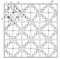
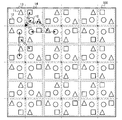
図1は、本実施例に係る光源装置100の構成の一例を示す。
図1に示すように、光源装置100は、マトリクス状に配置された複数の発光クラスタ13を有する。図1の例では、光源装置100は、3行3列の9個の発光クラスタ13を有する。
なお、複数の発光クラスタ13は、互いに分離されていてもよいし、互いに分離されていなくてもよい。
なお、発光クラスタの数は9個に限らない。発光クラスタの数は9個より多くても少なくてもよい。例えば、複数の発光クラスタは、2行2列の4個の発光クラスタであってもよいし、4行4列の16個の発光クラスタであってもよいし、2行5列の10個の発光クラスタであってもよい。
FIG. 1 shows an example of the configuration of a
As shown in FIG. 1, the
Note that the plurality of
Note that the number of light emitting clusters is not limited to nine. The number of light emitting clusters may be more or less than nine. For example, the plurality of light emitting clusters may be four light emitting clusters in 2 rows and 2 columns, 16 light emitting clusters in 4 rows and 4 columns, or 10 light emitting clusters in 2 rows and 5 columns. It may be a light emitting cluster.
発光クラスタ13は、第1の色の光を発する第1光源と、第1の色よりも輝度の違いが知覚されやすい第2の色の光を発する第2光源とを含む複数の光源を有する。具体的には、発光クラスタ13は、緑色LED10(G光源)、赤色LED11(R光源)、及び、青色LED12(B光源)を有する。緑色LED10は、緑色の光、具体的には主波長範囲が490nm〜549nmの光を発する光源である。赤色LED11は、赤色の光、具体的には主波長範囲が611nm以上の光を発する光源である。青色LED12は、青色の光、具体的には主波長範囲が430nm〜490nmの光を発する光源である。CIE1976UCS色度図からわかるように、人間の色覚上、赤色や青色は、緑色に比べて輝度の違いが知覚されやすい。そこで、本実施例では、緑色が第1の色、赤色が第2の色、青色が第3の色であり、緑色LED10が第1光源、赤色LED11が第2光源、青色LED12が第3光源であるものとする。また、本実施例では、発光クラスタ13の中心をP1と記載する。
なお、緑色が第1の色、赤色が第3の色、青色が第2の色であり、緑色LED10が第1光源、赤色LED11が第3光源、青色LED12が第2光源であってもよい。
なお、光源は発光ダイオード(LED)に限らない。例えば、光源は有機EL素子などであってもよい。
The
The green color may be the first color, the red color may be the third color, and the blue color may be the second color, the
The light source is not limited to a light emitting diode (LED). For example, the light source may be an organic EL element.
本実施例では、ローカルディミング制御を行う場合は、発光クラスタ毎に発する光の輝度が制御される。また、本実施例では、ローカルディミング制御を行う場合は、発光クラスタが有する複数の光源のそれぞれの発光輝度が、当該発光クラスタから所定の色の光が発せられるように制御される。具体的には、発光クラスタから白色の光が発せられるように、第1光源の発光輝度:第2光源の発光輝度:第3光源の発光輝度がおよそ7:3:1となるように第1光源〜第3光源の発光輝度が制御される。また、本実施例では、複数色の光源を使用することにより、単色の光源を使用する場合よりも、上記所定の色の光の色域を拡大することができる。具体的には、第1光源〜第3光源の発光輝度の比率を微調整することにより、上記所定の色の光の色度点を変更することができる。
なお、上記所定の色は白色でなくてもよい。
In the present embodiment, when local dimming control is performed, the luminance of light emitted for each light emitting cluster is controlled. In this embodiment, when local dimming control is performed, the light emission luminance of each of the plurality of light sources included in the light emission cluster is controlled so that light of a predetermined color is emitted from the light emission cluster. Specifically, the first light source luminance: the second light source luminance: the third light source luminance: about 7: 3: 1 so that white light is emitted from the light emission cluster. The light emission luminance of the light source to the third light source is controlled. Also, in this embodiment, by using a plurality of color light sources, the color gamut of the predetermined color light can be expanded as compared with the case of using a single color light source. Specifically, the chromaticity point of the predetermined color light can be changed by finely adjusting the ratio of the light emission luminance of the first light source to the third light source.
The predetermined color may not be white.
光源装置100が表示装置用の光源装置である場合、複数の発光クラスタ13は、画面を構成する複数の分割領域に対応するように設けられる。例えば、発光クラスタ13は、表示パネルの背面における対応分割領域(当該発光クラスタ13に対応する分割領域)に光を照射するように設けられる。具体的には、発光クラスタ13は、中心P1が対応分割領域の中心と一致するように設けられる。発光クラスタ13のサイズは、分割領域のサイズと同じであり、分割領域及び発光クラスタ13の形状は、正方形である。画面のアスペクト比が水平方向16:垂直方向9である場合、16の倍数で画面を水平方向に分割し、9の倍数で画面を垂直方向に分割することで正方形の分割領域が得られる。分割領域の数は、例えば、表示装置に求められるコントラストに基づいて決定される。
なお、発光クラスタ13のサイズは、分割領域のサイズより大きくても小さくてもよい。
また、分割領域や発光クラスタ13の形状は、正方形でなくてもよい。例えば、発光クラスタ13の形状は、正方形以外の四角形(長方形、平行四辺形、台形など)、円形、3角形、5角形などであってもよい。
When the
Note that the size of the
Further, the shape of the divided regions and the
発光クラスタ13は、2行2列の4つのサブ発光クラスタ14を有する。サブ発光クラスタ14は、上記複数の光源(第1光源と第2光源とを含む複数の光源)を有する。具体的には、サブ発光クラスタ14は、緑色LED10、赤色LED11、及び、青色LED12を有する。
なお、発光クラスタ13が有する4つのサブ発光クラスタは、互いに分離されていてもよいし、互いに分離されていなくてもよい。
The
Note that the four sub-light emitting clusters included in the
なお、光源装置100の外縁部(端部)には、外縁部における輝度と混色性(第1光源〜第3光源から発せられた光の合成性(混色性))を向上させるために、光の反射性が高い反射壁が設けられてもよい。光源装置100が表示装置用の光源装置である場合には、表示装置の表示領域(画面の領域)、または、表示領域を含む領域(表示領域より大きい領域)を囲むように、反射壁を設ければよい。
Note that the outer edge portion (end portion) of the
本実施例に係る光源装置における光源の配置について説明する。
まず、第1光源である緑色LED10の配置について説明する。
本実施例では、緑色LED10は、各サブ発光クラスタ14の中心に配置されている。図1の例では、光源装置100の発光領域(光が発せられる領域)の形状は正方形である。発光クラスタ13の発光領域は、光源装置100の発光領域を3行3列に等分割して得られる正方形の領域である。そして、サブ発光クラスタ14の発光領域は、発光クラスタ13の発光領域を2行2列に等分割して得られる正方形(1辺の長さがC1の正方形)の領域である。よって、本実施例では、光源装置は、計36個のサブ発光クラスタ14を有する。そして、緑色LED10は、水平方向(行方向)及び垂直方向(列方向)の間隔がC1となるように、各サブ発光クラスタ14に配置されている。上述したように、緑色LED10は、発光クラスタから光として白色の光を得る際に、複数の光源(緑色LED、赤色LED、青色LED)の中で最も高い輝度の光を発する光源である。そのような光源(緑色LED)をサブ発光クラスタの中心に配置することにより、全発光クラスタを同じ発光輝度で発光させた場合の輝度ムラを低減することができる。換言すれば、緑色LEDを等間隔に配置することにより、全発光クラスタを同じ発光輝度で発光させた場合の輝度ムラを低減することができる。
The arrangement of the light sources in the light source device according to this embodiment will be described.
First, the arrangement of the
In the present embodiment, the
次に、第2光源である赤色LED11と、第3光源である青色LED12との配置について説明する。
上述したように、赤色や青色は、緑色に比べて輝度の違いが知覚されやすい。そのため、ローカルディミング制御時に、互いに隣接する発光クラスタ間の赤色LED11の発光輝度の違いや、互いに隣接する発光クラスタ間の青色LED12の発光輝度の違いは色ム
ラとして知覚されやすい。
そこで、本実施例では、互いに隣接する発光クラスタ間の赤色LED11の間隔が短くなるように、赤色LED11を配置する。それにより、或る発光クラスタCL1が有する赤色LED11から発せられた赤色光と、当該発光クラスタCL1に隣接する発光クラスタCL2が有する赤色LED11から発せられた赤色光との混色性を高めることができる。その結果、互いに隣接する発光クラスタ間の赤色LED11の発光輝度の違いが知覚され難くなり、発光クラスタ間での色ムラを低減することができる。
同様に、本実施例では、互いに隣接する発光クラスタ間の青色LED12の間隔が短くなるように、青色LED12を配置する。それにより、或る発光クラスタCL1が有する青色LED12から発せられた青色光と、当該発光クラスタCL1に隣接する発光クラスタCL2が有する青色LED12から発せられた青色光との混色性を高めることができる。その結果、互いに隣接する発光クラスタ間の青色LED12の発光輝度の違いが知覚され難くなり、発光クラスタ間での色ムラを低減することができる。
Next, the arrangement of the red LED 11 as the second light source and the
As described above, red and blue are more likely to perceive a difference in luminance than green. Therefore, at the time of local dimming control, the difference in emission luminance of the red LED 11 between the adjacent emission clusters and the difference in emission luminance of the
Therefore, in this embodiment, the red LEDs 11 are arranged so that the interval between the red LEDs 11 between the light emitting clusters adjacent to each other is shortened. Accordingly, it is possible to improve the color mixing property between the red light emitted from the red LED 11 included in a certain light emitting cluster CL1 and the red light emitted from the red LED 11 included in the light emitting cluster CL2 adjacent to the light emitting cluster CL1. As a result, it becomes difficult to perceive the difference in light emission luminance of the red LEDs 11 between the light emitting clusters adjacent to each other, and color unevenness between the light emitting clusters can be reduced.
Similarly, in this embodiment, the
なお、赤色LED11と青色LED12の一方のLEDについてのみ、互いに隣接する発光クラスタ間のLEDの間隔が短くなるように、LEDが配置されてもよい。互いに隣接する発光クラスタ間のLED(輝度の違いが知覚されやすい色の光を発するLED)の間隔が短くなるように、当該LEDを配置すれば、当該LEDの発光輝度の違いによる色ムラを低減できる。 In addition, about only one LED of red LED11 and blue LED12, LED may be arrange | positioned so that the space | interval of LED between the mutually adjacent light emission clusters may become short. If the LEDs are arranged so that the interval between LEDs (LEDs that emit light of a color whose luminance difference is easily perceived) between adjacent light emitting clusters is shortened, color unevenness due to the difference in emission luminance of the LEDs is reduced. it can.
赤色LED11と青色LED12の配置についてより詳細に説明する。
本実施例では、以下の条件式1,2を満たすように、赤色LED11と青色LED12が配置される。条件式1,2において、A1は、発光クラスタの中心P1と、当該発光クラスタが有する緑色LED10との間の距離である。B1は、発光クラスタの中心P1と、当該発光クラスタが有する赤色LED11との間の距離、及び、発光クラスタの中心P1と、当該発光クラスタが有する青色LED12との間の距離である。C1は、発光クラスタが有する緑色LED10と、隣接する発光クラスタが有する緑色LED10との間の距離(緑色LED10の垂直方向及び水平方向の間隔)である。D1は、発光クラスタが有する赤色LED11と、隣接する発光クラスタが有する赤色LED11との間の距離、及び、発光クラスタが有する青色LED12と、隣接する発光クラスタが有する青色LED12との間の距離である。
A1≦B1 ・・・(条件式1)
D1<C1 ・・・(条件式2)
条件式1は、発光クラスタの中心と、当該発光クラスタが有する赤色LED及び青色LEDとの間の距離が、発光クラスタの中心と、当該発光クラスタが有する緑色LEDとの間の距離以上であるという条件を表す式である。条件式2は、発光クラスタが有する緑色LEDと、隣接する発光クラスタが有する緑色LEDとの間の距離が、発光クラスタが有する赤色LED及び青色LEDと、隣接する発光クラスタが有する緑色LEDとの間の距離よりも短いという条件を表す式である。条件式1,2を満たす配置により、互いに隣接する発光クラスタ間の赤色LED11の間隔及び青色LED12の間隔を、互いに隣接する発光クラスタ間の緑色LED10の間隔よりも短くすることができ、発光クラスタ間の色ムラを低減することができる。
The arrangement of the red LED 11 and the
In the present embodiment, the red LED 11 and the
A1 ≦ B1 (Condition 1)
D1 <C1 (Condition 2)
Conditional expression 1 indicates that the distance between the center of the light emitting cluster and the red LED and the blue LED included in the light emitting cluster is equal to or greater than the distance between the center of the light emitting cluster and the green LED included in the light emitting cluster. It is a formula representing a condition.
図1の例では、2行2列の4つのサブ発光クラスタのうち、1行2列目に配置されているサブ発光クラスタが有する3つのLED(緑色LED、赤色LED、及び、青色LED)は、水平方向に対する角度が45度の方向に並べて配置されている。2行1列目に配置されているサブ発光クラスタが有する3つのLEDも、水平方向に対する角度が45度の方向に並べて配置されている。また、1行1列目に配置されているサブ発光クラスタが有
する3つのLED、及び、2行2列目に配置されているサブ発光クラスタが有する3つのLEDは、水平方向に対する角度が135度の方向に並べて配置されている。
このような配置により、条件式1,2が満たされる。
In the example of FIG. 1, three LEDs (green LED, red LED, and blue LED) included in the sub light emitting cluster arranged in the first row and the second column among the four sub light emitting clusters of 2 rows and 2 columns are: The angle with respect to the horizontal direction is arranged in the direction of 45 degrees. The three LEDs of the sub-light emitting cluster arranged in the second row and the first column are also arranged side by side in a direction whose angle with respect to the horizontal direction is 45 degrees. In addition, the three LEDs included in the sub light emission cluster arranged in the first row and the first column and the three LEDs included in the sub light emission cluster arranged in the second row and the second column have an angle with respect to the horizontal direction of 135 degrees. Are arranged side by side.
以上述べたように、本実施例によれば、上述した条件式1,2を満たすように各光源が配置される。それにより、各々が複数色の光源を有する複数の発光クラスタを有する光源装置においてローカルディミング制御を行うことにより生じる発光クラスタ間での色ムラを低減することができる。
As described above, according to the present embodiment, each light source is arranged so as to satisfy the
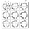
なお、図1は、A1<B1の場合の例であるが、条件式1からもわかるように、A1=B1であってもよい。A1=A2の場合の一例を図4に示す。図4の例においても、条件式1,2が満たされるため、発光クラスタ間の色ムラを低減することができる。
なお、条件式2を満たせば、互いに隣接する発光クラスタ間の赤色LED11の間隔及び青色LED12の間隔を短くすることができ、発光クラスタ間の色ムラを低減することができる。そのため、条件式2のみを満たすように各光源が配置されてもよい。条件式2のみを満たす場合の一例を図5に示す。また、条件式1を満たすように配置すれば、満たさない場合に比べて、隣接する発光クラスタまでの赤色LEDと青色LEDの距離を短くすることができ、発光クラスタ間の色ムラを低減することができる。そのため、条件式1のみを満たすように各光源が配置されてもよい。
なお、図5からわかるように、緑色LEDはサブ発光クラスタの中心に配置されていなくてもよい。
なお、図1は、発光クラスタが2行2列の4つのサブ発光クラスタを有する場合の例であるが、発光クラスタはサブ発光クラスタを有していなくてもよい。発光クラスタがサブ発光クラスタを有さない場合の例を図6に示す。図6の例においても、条件式2が満たされるため、発光クラスタ間の色ムラを低減することができる。
なお、発光クラスタの中心と、当該発光クラスタが有する赤色LEDとの間の距離、及び、発光クラスタの中心と、当該発光クラスタが有する青色LEDとの間の距離は互いに異なっていてもよい。そして、発光クラスタが有する赤色LEDと、隣接する発光クラスタが有する赤色LEDとの間の距離、及び、発光クラスタが有する青色LEDと、隣接する発光クラスタが有する青色LEDとの間の距離は、互いに異なっていてもよい。そのような構成であっても、条件式1、条件式2、または、それら両方を満たせば、発光クラスタ間の色ムラを低減することができる。
1 is an example in the case of A1 <B1, but as can be seen from the conditional expression 1, A1 = B1 may be used. An example in the case of A1 = A2 is shown in FIG. Also in the example of FIG. 4, since the
If
As can be seen from FIG. 5, the green LED does not have to be arranged at the center of the sub-emission cluster.
FIG. 1 shows an example in which the light emission cluster has four sub light emission clusters of 2 rows and 2 columns, but the light emission cluster may not have the sub light emission cluster. FIG. 6 shows an example in which the light emission cluster does not have a sub light emission cluster. Also in the example of FIG. 6, since the
Note that the distance between the center of the light emitting cluster and the red LED included in the light emitting cluster and the distance between the center of the light emitting cluster and the blue LED included in the light emitting cluster may be different from each other. The distance between the red LED of the light emitting cluster and the red LED of the adjacent light emitting cluster, and the distance between the blue LED of the light emitting cluster and the blue LED of the adjacent light emitting cluster are mutually different. May be different. Even in such a configuration, if the conditional expression 1, the
<実施例2>
以下、本発明の実施例2に係る光源装置について説明する。実施例1では、緑色LED、赤色LED、及び、青色LEDの3種類の光源を用いる構成について説明した。本実施例では、2種類の光源を用いる構成について説明する。具体的には、シアン色の光を発する光源であるシアン色LED(C光源)と、赤色の光を発する光源である赤色LED(R光源)とを用いる構成について説明する。赤色は、シアン色に比べて輝度の違いが知覚されやすい。そこで、本実施例では、シアン色が第1の色、赤色が第2の色であり、シアン色LEDが第1光源、赤色LEDが第2光源であるものとする。
なお、2種類の光源は、C光源とR光源に限らない。例えば、2種類の光源は、緑色の光を発するG光源とマゼンダ色の光を発するM光源とであってもよい。その場合、緑色が第1の色、マゼンダ色が第2の色となり、G光源が第1光源、M光源が第2光源となる。
<Example 2>
Hereinafter, a light source device according to a second embodiment of the invention will be described. In the first embodiment, the configuration using the three types of light sources of the green LED, the red LED, and the blue LED has been described. In this embodiment, a configuration using two types of light sources will be described. Specifically, a configuration using a cyan LED (C light source) that is a light source that emits cyan light and a red LED (R light source) that is a light source that emits red light will be described. In red, a difference in luminance is more easily perceived than in cyan. Therefore, in this embodiment, it is assumed that cyan is the first color, red is the second color, cyan LED is the first light source, and red LED is the second light source.
The two types of light sources are not limited to the C light source and the R light source. For example, the two types of light sources may be a G light source that emits green light and an M light source that emits magenta light. In that case, green is the first color, magenta is the second color, the G light source is the first light source, and the M light source is the second light source.
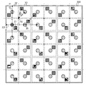
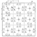
図2は、本実施例に係る光源装置200の構成の一例を示す。
光源装置200は、実施例1(図1)と同様に、マトリクス状に配置された複数の発光クラスタ22を有する。図2の例では、光源装置200は、3行3列の9個の発光クラスタ22を有する。ローカルディミング制御を行う場合は、発光クラスタ22毎に発する光の輝度が制御される。
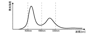
発光クラスタ22は、実施例1(図1)と同様に、2行2列の4つのサブ発光クラスタ23を有する。サブ発光クラスタ23は、シアン色LED20と赤色LED21を有する。シアン色LED20は、シアン色の光、具体的には主波長範囲が430nm〜490nmの光を緑色の蛍光体で励起した光を発する光源である。シアン色LED20から発せられる光は、例えば、図3に示すような分光特性を有する。即ち、シアン色LED20から発せられる光の分光特性は、例えば、ピークを2つ有する。図3の横軸は波長を示し、縦軸は発光強度を示す。赤色LED21は、赤色の光、具体的には主波長範囲が611nm以上の光を発する光源である。
FIG. 2 shows an example of the configuration of the
The
The light emitting cluster 22 has four sub
本実施例に係る光源装置における光源の配置について説明する。
まず、第1光源であるシアン色LED20の配置について説明する。
本実施例では、シアン色LED20は、各サブ発光クラスタ23の中心に配置されている。図2の例では、光源装置200の発光領域の形状は正方形である。発光クラスタ22の発光領域は、光源装置200の発光領域を3行3列に等分割して得られる正方形の領域である。そして、サブ発光クラスタ23の発光領域は、発光クラスタ22の発光領域を2行2列に等分割して得られる正方形(1辺の長さがC2の正方形)の領域である。よって、本実施例では、光源装置は、計36個のサブ発光クラスタ23を有する。そして、シアン色LED20は、水平方向(行方向)及び垂直方向(列方向)の間隔がC2となるように、各サブ発光クラスタ23に配置されている。シアン色LED20は、発光クラスタから光として白色の光を得る際に、赤色LED21よりも高い輝度の光を発する光源である。そのような光源(シアン色LED)をサブ発光クラスタの中心に配置することにより、全発光クラスタを同じ発光輝度で発光させた場合の輝度ムラを低減することができる。換言すれば、シアン色LEDを等間隔に配置することにより、全発光クラスタを同じ発光輝度で発光させた場合の輝度ムラを低減することができる。
The arrangement of the light sources in the light source device according to this embodiment will be described.
First, the arrangement of the
In this embodiment, the
次に、第2光源である赤色LED21の配置について説明する。
上述したように、赤色は、シアン色に比べて輝度の違いが知覚されやすい。そのため、ローカルディミング制御時に、互いに隣接する発光クラスタ間の赤色LED21の発光輝度の違いは色ムラとして知覚されやすい。
そこで、本実施例では、互いに隣接する発光クラスタ間の赤色LED21の間隔が短くなるように、赤色LED21を配置する。それにより、互いに隣接する発光クラスタ間の赤色LED21の発光輝度の違いが知覚され難くなり、発光クラスタ間での色ムラを低減することができる。
Next, the arrangement of the
As described above, red is more susceptible to perceived differences in luminance than cyan. Therefore, at the time of local dimming control, a difference in emission luminance of the
Therefore, in this embodiment, the
赤色LED21の配置についてより詳細に説明する。
本実施例では、以下の条件式3,4を満たすように、赤色LED21が配置される。条件式3,4において、A2は、発光クラスタの中心P2と、当該発光クラスタが有するシアン色LED20との間の距離である。B2は、発光クラスタの中心P2と、当該発光クラスタが有する赤色LED21との間の距離である。C2は、発光クラスタが有するシアン色LED20と、隣接する発光クラスタが有するシアン色LED20との間の距離(シアン色LED20の垂直方向及び水平方向の間隔)である。D2は、発光クラスタが有する赤色LED21と、隣接する発光クラスタが有する赤色LED21との間の距離である。
A2≦B2 ・・・(条件式3)
D2<C2 ・・・(条件式4)
即ち、本実施例では、距離B2が距離A2以上となり、距離D2が距離C2よりも短くなるように、各光源が配置される。そのような配置により、互いに隣接する発光クラスタ間の赤色LED21の間隔を、互いに隣接する発光クラスタ間のシアン色LED20の間
隔よりも短くすることができ、発光クラスタ間の色ムラを低減することができる。
The arrangement of the
In the present embodiment, the
A2 ≦ B2 (Condition 3)
D2 <C2 (Condition 4)
That is, in this embodiment, each light source is arranged so that the distance B2 is equal to or greater than the distance A2, and the distance D2 is shorter than the distance C2. With such an arrangement, the distance between the
図2の例では、2行2列の4つのサブ発光クラスタのうち、1行2列目に配置されているサブ発光クラスタが有する2つのLED(シアン色LEDと赤色LED)は、水平方向に対する角度が45度の方向に並べて配置されている。2行1列目に配置されているサブ発光クラスタが有する2つのLEDも、水平方向に対する角度が45度の方向に並べて配置されている。また、1行1列目に配置されているサブ発光クラスタが有する2つのLED、及び、2行2列目に配置されているサブ発光クラスタが有する2つのLEDは、水平方向に対する角度が135度の方向に並べて配置されている。
このような配置により、条件式3,4が満たされる。
In the example of FIG. 2, two LEDs (cyan LED and red LED) included in the sub light emitting cluster arranged in the first row and the second column among the four sub light emitting clusters of 2 rows and 2 columns are in the horizontal direction. The angles are arranged side by side in the direction of 45 degrees. The two LEDs of the sub-light emitting cluster arranged in the second row and the first column are also arranged side by side in a direction whose angle with respect to the horizontal direction is 45 degrees. In addition, the two LEDs included in the sub light emission cluster arranged in the first row and the first column and the two LEDs included in the sub light emission cluster arranged in the second row and the second column have an angle with respect to the horizontal direction of 135 degrees. Are arranged side by side.
Conditional expressions 3 and 4 are satisfied by such an arrangement.
以上述べたように、本実施例によれば、上述した条件3,4を満たすように各光源が配置される。それにより、各々が複数色の光源を有する複数の発光クラスタを有する光源装置においてローカルディミング制御を行うことにより生じる発光クラスタ間での色ムラを低減することができる。
なお、実施例1(図4〜6)と同様に、本実施例に係る光源装置の構成も、種々の変更が可能である。
As described above, according to the present embodiment, each light source is arranged so as to satisfy the conditions 3 and 4 described above. Accordingly, it is possible to reduce color unevenness between light emitting clusters caused by performing local dimming control in a light source device having a plurality of light emitting clusters each having a light source of a plurality of colors.
As in the first embodiment (FIGS. 4 to 6), the configuration of the light source device according to the present embodiment can be variously changed.
100,200:光源装置 13,22:発光クラスタ 14,23:サブ発光クラスタ 10:緑色LED 11,21:赤色LED 12:青色LED 20:シアン色L
ED
100, 200:
ED
Claims (7)
マトリクス状に配置された複数の発光クラスタを有し、
前記発光クラスタは、2行2列の4つのサブ発光クラスタを有し、
前記サブ発光クラスタは、第1の色の光を発する第1光源と、前記第1の色よりも輝度の違いが知覚されやすい第2の色の光を発する第2光源とを含む複数の光源を有し、
前記発光クラスタの中心と、当該発光クラスタが有する第2光源との間の距離は、前記発光クラスタの中心と、当該発光クラスタが有する第1光源との間の距離以上である
ことを特徴とする光源装置。 A light source device capable of controlling the brightness of light emitted for each light emitting cluster,
Having a plurality of light emitting clusters arranged in a matrix;
The light emission cluster has four sub light emission clusters of 2 rows and 2 columns,
The sub-light emitting cluster includes a plurality of light sources including a first light source that emits light of a first color and a second light source that emits light of a second color in which a difference in luminance is more easily perceived than the first color. Have
The distance between the center of the light emitting cluster and the second light source of the light emitting cluster is equal to or greater than the distance between the center of the light emitting cluster and the first light source of the light emitting cluster. Light source device.
マトリクス状に配置された複数の発光クラスタを有し、
前記発光クラスタは、第1の色の光を発する第1光源と、前記第1の色よりも輝度の違いが知覚されやすい第2の色の光を発する第2光源とを含む複数の光源を有し、
前記発光クラスタが有する第2光源と、隣接する発光クラスタが有する第2光源との間の距離は、前記発光クラスタが有する第1光源と、隣接する発光クラスタが有する第1光源との間の距離よりも短い
ことを特徴とする光源装置。 A light source device capable of controlling the brightness of light emitted for each light emitting cluster,
Having a plurality of light emitting clusters arranged in a matrix;
The light emitting cluster includes a plurality of light sources including a first light source that emits light of a first color and a second light source that emits light of a second color in which a difference in luminance is more easily perceived than the first color. Have
The distance between the second light source of the light emitting cluster and the second light source of the adjacent light emitting cluster is the distance between the first light source of the light emitting cluster and the first light source of the adjacent light emitting cluster. A light source device characterized in that the light source device is shorter.
ことを特徴とする請求項1に記載の光源装置。 The distance between the second light source of the light emitting cluster and the second light source of the adjacent light emitting cluster is the distance between the first light source of the light emitting cluster and the first light source of the adjacent light emitting cluster. The light source device according to claim 1, wherein the light source device is shorter.
前記サブ発光クラスタは、前記複数の光源を有し、
前記複数の光源のそれぞれの発光輝度は、前記発光クラスタから所定の色の光が発せられるように制御されるものであり、
前記第1光源は、前記複数の光源の中で最も高い輝度の光を発する光源であり、
前記第1光源は、前記サブ発光クラスタの中心に配置されている
ことを特徴とする請求項1〜3のいずれか1項に記載の光源装置。 The light emission cluster has four sub light emission clusters of 2 rows and 2 columns,
The sub-emission cluster has the plurality of light sources,
The light emission luminance of each of the plurality of light sources is controlled so that light of a predetermined color is emitted from the light emission cluster,
The first light source is a light source that emits light having the highest luminance among the plurality of light sources,
The light source device according to claim 1, wherein the first light source is disposed at a center of the sub light emission cluster.
前記第1光源はG光源であり、
前記第2光源はR光源またはB光源である
ことを特徴とする請求項1〜4のいずれか1項に記載の光源装置。 The plurality of light sources are an R light source that emits red light, a G light source that emits green light, and a B light source that emits blue light,
The first light source is a G light source;
5. The light source device according to claim 1, wherein the second light source is an R light source or a B light source.
前記第1光源はC光源であり、
前記第2光源はR光源である
ことを特徴とする請求項1〜4のいずれか1項に記載の光源装置。 The plurality of light sources are a C light source that emits cyan light and an R light source that emits red light,
The first light source is a C light source;
The light source device according to claim 1, wherein the second light source is an R light source.
前記サブ発光クラスタは、前記複数の光源を有し、
前記4つのサブ発光クラスタのうち、1行2列目に配置されているサブ発光クラスタが有する第1光源と第2光源、及び、2行1列目に配置されているサブ発光クラスタが有する第1光源と第2光源は、水平方向に対する角度が45度の方向に並べて配置されており
、
前記4つのサブ発光クラスタのうち、1行1列目に配置されているサブ発光クラスタが有する第1光源と第2光源、及び、2行2列目に配置されているサブ発光クラスタが有する第1光源と第2光源は、水平方向に対する角度が135度の方向に並べて配置されている
ことを特徴とする請求項1〜6のいずれか1項に記載の光源装置。 The light emission cluster has four sub light emission clusters of 2 rows and 2 columns,
The sub-emission cluster has the plurality of light sources,
Of the four sub-light-emitting clusters, the first light source and the second light source included in the sub-light-emitting cluster arranged in the first row and the second column, and the first light source cluster included in the second light-emitting cluster arranged in the second row and the first column. The first light source and the second light source are arranged side by side in a direction whose angle with respect to the horizontal direction is 45 degrees.
Of the four sub-light-emitting clusters, the first light source and the second light source included in the sub-light-emitting cluster arranged in the first row and the first column, and the first light source and the second light source included in the second row and the second column. The light source device according to claim 1, wherein the first light source and the second light source are arranged side by side in a direction having an angle of 135 degrees with respect to the horizontal direction.
Priority Applications (2)
| Application Number | Priority Date | Filing Date | Title |
|---|---|---|---|
| JP2013101238A JP2014222575A (en) | 2013-05-13 | 2013-05-13 | Light source device |
| US14/273,293 US9389457B2 (en) | 2013-05-13 | 2014-05-08 | Light source apparatus |
Applications Claiming Priority (1)
| Application Number | Priority Date | Filing Date | Title |
|---|---|---|---|
| JP2013101238A JP2014222575A (en) | 2013-05-13 | 2013-05-13 | Light source device |
Publications (2)
| Publication Number | Publication Date |
|---|---|
| JP2014222575A true JP2014222575A (en) | 2014-11-27 |
| JP2014222575A5 JP2014222575A5 (en) | 2016-06-16 |
Family
ID=51864642
Family Applications (1)
| Application Number | Title | Priority Date | Filing Date |
|---|---|---|---|
| JP2013101238A Pending JP2014222575A (en) | 2013-05-13 | 2013-05-13 | Light source device |
Country Status (2)
| Country | Link |
|---|---|
| US (1) | US9389457B2 (en) |
| JP (1) | JP2014222575A (en) |
Cited By (1)
| Publication number | Priority date | Publication date | Assignee | Title |
|---|---|---|---|---|
| JP2016184498A (en) * | 2015-03-26 | 2016-10-20 | シャープ株式会社 | Backlight device and liquid crystal display device including the same |
Families Citing this family (2)
| Publication number | Priority date | Publication date | Assignee | Title |
|---|---|---|---|---|
| CN112997234B (en) * | 2019-09-19 | 2023-03-24 | 瑞仪光电(苏州)有限公司 | Light source structure, backlight module and display device |
| CN110610930A (en) * | 2019-09-26 | 2019-12-24 | 纳米格有限公司 | LED packaging unit, LED lamp and manufacturing method |
Citations (2)
| Publication number | Priority date | Publication date | Assignee | Title |
|---|---|---|---|---|
| JP2005243347A (en) * | 2004-02-25 | 2005-09-08 | Sharp Corp | Light emitting device and display device using it |
| JP2008003220A (en) * | 2006-06-21 | 2008-01-10 | Sony Corp | Planar light source device |
Family Cites Families (2)
| Publication number | Priority date | Publication date | Assignee | Title |
|---|---|---|---|---|
| KR100809264B1 (en) | 2006-07-25 | 2008-03-03 | 삼성전기주식회사 | Surface light source device and backlight unit having the same |
| KR101488042B1 (en) * | 2007-05-20 | 2015-01-29 | 쓰리엠 이노베이티브 프로퍼티즈 컴파니 | Design parameters for thin hollow cavity backlights of the light-recycling type |
-
2013
- 2013-05-13 JP JP2013101238A patent/JP2014222575A/en active Pending
-
2014
- 2014-05-08 US US14/273,293 patent/US9389457B2/en active Active
Patent Citations (2)
| Publication number | Priority date | Publication date | Assignee | Title |
|---|---|---|---|---|
| JP2005243347A (en) * | 2004-02-25 | 2005-09-08 | Sharp Corp | Light emitting device and display device using it |
| JP2008003220A (en) * | 2006-06-21 | 2008-01-10 | Sony Corp | Planar light source device |
Cited By (1)
| Publication number | Priority date | Publication date | Assignee | Title |
|---|---|---|---|---|
| JP2016184498A (en) * | 2015-03-26 | 2016-10-20 | シャープ株式会社 | Backlight device and liquid crystal display device including the same |
Also Published As
| Publication number | Publication date |
|---|---|
| US9389457B2 (en) | 2016-07-12 |
| US20140334144A1 (en) | 2014-11-13 |
Similar Documents
| Publication | Publication Date | Title |
|---|---|---|
| JP6178027B2 (en) | Partially driven light source device and image display device using the same | |
| KR101750022B1 (en) | Organic Light Emitting Diode Display Device | |
| KR101531227B1 (en) | Lighting apparatus | |
| US8138687B2 (en) | Multicolor lighting system | |
| JP6243100B2 (en) | Light guide plate and backlight assembly including the same | |
| JP2007227389A (en) | Multi-colored led array with improved color uniformity | |
| JP2006338020A (en) | Backlight assembly for liquid crystal display device and liquid crystal display device using same | |
| BRPI1000097A2 (en) | color display unit | |
| JP6091559B2 (en) | Light source device and image display device | |
| US9784416B2 (en) | Multi-coloured light sources | |
| TW201448304A (en) | Organic light emitting diode display | |
| US8363182B2 (en) | Liquid crystal display device having illumination element emitting colors independently via time division | |
| US9389457B2 (en) | Light source apparatus | |
| US20120001964A1 (en) | Liquid crystal display apparatus | |
| US8876353B2 (en) | Lighting apparatus | |
| US20170336677A1 (en) | Lighting device and display device | |
| JP2008010392A (en) | Device with three-primary-color light emitting diodes arranged in matrix | |
| US20170168210A1 (en) | Backlight module, display module, and display device | |
| JP4241790B2 (en) | Lighting device, backlight device, liquid crystal display device | |
| US9627446B2 (en) | Display device | |
| JP2009181883A (en) | Backlight device | |
| RU2617558C2 (en) | Light emitting device for backlight device and method of operation light emitting device | |
| US20150055336A1 (en) | Pixel structure and display using the same | |
| US20090051642A1 (en) | Backlight assembly, method of driving the same and display system having the same thereof | |
| US8801259B2 (en) | Light emitting diode light bar structure and backlight module |
Legal Events
| Date | Code | Title | Description |
|---|---|---|---|
| A521 | Written amendment |
Free format text: JAPANESE INTERMEDIATE CODE: A523 Effective date: 20160419 |
|
| A621 | Written request for application examination |
Free format text: JAPANESE INTERMEDIATE CODE: A621 Effective date: 20160419 |
|
| A977 | Report on retrieval |
Free format text: JAPANESE INTERMEDIATE CODE: A971007 Effective date: 20170131 |
|
| A131 | Notification of reasons for refusal |
Free format text: JAPANESE INTERMEDIATE CODE: A131 Effective date: 20170228 |
|
| A02 | Decision of refusal |
Free format text: JAPANESE INTERMEDIATE CODE: A02 Effective date: 20170905 |