JP2014221468A - Airbrush - Google Patents
Airbrush Download PDFInfo
- Publication number
- JP2014221468A JP2014221468A JP2013102602A JP2013102602A JP2014221468A JP 2014221468 A JP2014221468 A JP 2014221468A JP 2013102602 A JP2013102602 A JP 2013102602A JP 2013102602 A JP2013102602 A JP 2013102602A JP 2014221468 A JP2014221468 A JP 2014221468A
- Authority
- JP
- Japan
- Prior art keywords
- needle cap
- nozzle
- cylindrical body
- air brush
- protrusion
- Prior art date
- Legal status (The legal status is an assumption and is not a legal conclusion. Google has not performed a legal analysis and makes no representation as to the accuracy of the status listed.)
- Granted
Links
- 239000003973 paint Substances 0.000 claims description 42
- XEEYBQQBJWHFJM-UHFFFAOYSA-N Iron Chemical compound [Fe] XEEYBQQBJWHFJM-UHFFFAOYSA-N 0.000 claims description 8
- 239000000696 magnetic material Substances 0.000 claims description 6
- 229910052742 iron Inorganic materials 0.000 claims description 4
- 239000011248 coating agent Substances 0.000 abstract description 2
- 238000000576 coating method Methods 0.000 abstract description 2
- 239000000463 material Substances 0.000 abstract 1
- 230000002093 peripheral effect Effects 0.000 description 8
- 238000010586 diagram Methods 0.000 description 5
- 238000002347 injection Methods 0.000 description 4
- 239000007924 injection Substances 0.000 description 4
- 239000007921 spray Substances 0.000 description 3
- 238000000034 method Methods 0.000 description 2
- 238000010422 painting Methods 0.000 description 2
- 238000007789 sealing Methods 0.000 description 2
- 238000005452 bending Methods 0.000 description 1
- 230000007547 defect Effects 0.000 description 1
- 238000003780 insertion Methods 0.000 description 1
- 230000037431 insertion Effects 0.000 description 1
- 239000007788 liquid Substances 0.000 description 1
- 239000002184 metal Substances 0.000 description 1
- 229910052751 metal Inorganic materials 0.000 description 1
- 239000003595 mist Substances 0.000 description 1
- 239000000203 mixture Substances 0.000 description 1
- 238000012986 modification Methods 0.000 description 1
- 230000004048 modification Effects 0.000 description 1
- 239000011347 resin Substances 0.000 description 1
- 229920005989 resin Polymers 0.000 description 1
- 238000001179 sorption measurement Methods 0.000 description 1
Images


Classifications
-
- B—PERFORMING OPERATIONS; TRANSPORTING
- B05—SPRAYING OR ATOMISING IN GENERAL; APPLYING FLUENT MATERIALS TO SURFACES, IN GENERAL
- B05B—SPRAYING APPARATUS; ATOMISING APPARATUS; NOZZLES
- B05B7/00—Spraying apparatus for discharge of liquids or other fluent materials from two or more sources, e.g. of liquid and air, of powder and gas
- B05B7/02—Spray pistols; Apparatus for discharge
-
- B—PERFORMING OPERATIONS; TRANSPORTING
- B05—SPRAYING OR ATOMISING IN GENERAL; APPLYING FLUENT MATERIALS TO SURFACES, IN GENERAL
- B05B—SPRAYING APPARATUS; ATOMISING APPARATUS; NOZZLES
- B05B15/00—Details of spraying plant or spraying apparatus not otherwise provided for; Accessories
- B05B15/14—Arrangements for preventing or controlling structural damage to spraying apparatus or its outlets, e.g. for breaking at desired places; Arrangements for handling or replacing damaged parts
- B05B15/16—Arrangements for preventing or controlling structural damage to spraying apparatus or its outlets, e.g. for breaking at desired places; Arrangements for handling or replacing damaged parts for preventing non-intended contact between spray heads or nozzles and foreign bodies, e.g. nozzle guards
-
- B—PERFORMING OPERATIONS; TRANSPORTING
- B43—WRITING OR DRAWING IMPLEMENTS; BUREAU ACCESSORIES
- B43K—IMPLEMENTS FOR WRITING OR DRAWING
- B43K8/00—Pens with writing-points other than nibs or balls
- B43K8/006—Pens with writing-points other than nibs or balls using a spraying system, e.g. airbrushes
-
- B—PERFORMING OPERATIONS; TRANSPORTING
- B05—SPRAYING OR ATOMISING IN GENERAL; APPLYING FLUENT MATERIALS TO SURFACES, IN GENERAL
- B05B—SPRAYING APPARATUS; ATOMISING APPARATUS; NOZZLES
- B05B7/00—Spraying apparatus for discharge of liquids or other fluent materials from two or more sources, e.g. of liquid and air, of powder and gas
- B05B7/24—Spraying apparatus for discharge of liquids or other fluent materials from two or more sources, e.g. of liquid and air, of powder and gas with means, e.g. a container, for supplying liquid or other fluent material to a discharge device
- B05B7/2402—Apparatus to be carried on or by a person, e.g. by hand; Apparatus comprising containers fixed to the discharge device
- B05B7/2405—Apparatus to be carried on or by a person, e.g. by hand; Apparatus comprising containers fixed to the discharge device using an atomising fluid as carrying fluid for feeding, e.g. by suction or pressure, a carried liquid from the container to the nozzle
- B05B7/2435—Apparatus to be carried on or by a person, e.g. by hand; Apparatus comprising containers fixed to the discharge device using an atomising fluid as carrying fluid for feeding, e.g. by suction or pressure, a carried liquid from the container to the nozzle the carried liquid and the main stream of atomising fluid being brought together by parallel conduits placed one inside the other
-
- B—PERFORMING OPERATIONS; TRANSPORTING
- B05—SPRAYING OR ATOMISING IN GENERAL; APPLYING FLUENT MATERIALS TO SURFACES, IN GENERAL
- B05B—SPRAYING APPARATUS; ATOMISING APPARATUS; NOZZLES
- B05B7/00—Spraying apparatus for discharge of liquids or other fluent materials from two or more sources, e.g. of liquid and air, of powder and gas
- B05B7/24—Spraying apparatus for discharge of liquids or other fluent materials from two or more sources, e.g. of liquid and air, of powder and gas with means, e.g. a container, for supplying liquid or other fluent material to a discharge device
- B05B7/2402—Apparatus to be carried on or by a person, e.g. by hand; Apparatus comprising containers fixed to the discharge device
- B05B7/2478—Gun with a container which, in normal use, is located above the gun
Landscapes
- Nozzles (AREA)
Abstract
Description
本発明はエアーブラシに係り、特に、そのノズルの先端にニードルキャップを備えるエアーブラシに関する。 The present invention relates to an air brush, and more particularly to an air brush having a needle cap at the tip of a nozzle.
エアーブラシは、圧縮した空気によって塗料を霧状に飛ばす道具であり、筆では難しいムラのない塗装が簡単にできるようになっている。 An air brush is a tool that blows paint in the form of a mist with compressed air, and can be easily applied without unevenness, which is difficult with a brush.
このようなエアーブラシは、たとえば下記特許文献1に記載されているように、ほぼペンシルに似た形状をなすエアーブラシ本体を具備する。そして、エアーブラシ本体の先端には、塗料流と空気流を噴射させるノズルが設けられている。ノズルの後部のエアーブラシ本体の上部には塗料容器が設けられ、該塗料容器内の塗料は後述の操作杆の操作によってノズル内に導かれるようになっている。エアーブラシ本体のほぼ中央には、圧縮空気を供給する空気供給口部と、この空気供給口部から供給された圧縮空気をノズルの外周に導く操作杆とが設けられている。エアーブラシ本体の軸芯部には、その先端が該ノズルの塗料噴射孔をシールするように付勢されたニードルが内蔵され、上述の操作杆の操作による該ニードルの後退によって該シールを解除できるようになっている。 Such an air brush includes an air brush body having a shape substantially similar to a pencil, as described in, for example, Patent Document 1 below. And the nozzle which injects a paint flow and an air flow is provided in the front-end | tip of the airbrush main body. A paint container is provided in the upper part of the airbrush main body at the rear of the nozzle, and the paint in the paint container is guided into the nozzle by an operation of an operation rod described later. An air supply port for supplying compressed air and an operating rod for guiding the compressed air supplied from the air supply port to the outer periphery of the nozzle are provided at substantially the center of the air brush body. The air brush body has a shaft core with a built-in needle whose tip is urged so as to seal the paint injection hole of the nozzle, and the seal can be released by the retraction of the needle by the operation of the operation rod described above. It is like that.
このように構成されるエアーブラシは、操作杆をエアーブラシ本体側へ押すことにより、空気供給口部からの圧縮空気をノズルの外周に沿って噴出させ、さらに、操作杆を後方へ移動させることにより、ニードルによるシールが解除されたノズルの塗料噴射孔を通して塗料を吹き出させるようになっている。 The airbrush configured in this manner causes the compressed air from the air supply port portion to be ejected along the outer periphery of the nozzle by pushing the operating rod toward the air brush main body, and further moves the operating rod backward. Thus, the paint is blown out through the paint injection hole of the nozzle whose seal by the needle is released.
ここで、ノズルの塗料噴射孔のニードルによるシールは、たとえば、ニードルの先端部をノズルの塗料噴射孔に抜き差し自在に貫通せしめる弁構造によって行っている。
塗料噴射孔からニードルが突出しているノズルの先端部は、被塗物等との接触によってニードルの破損や曲がり、変形が生じやすく、噴出される塗料の線の太さや噴出の向きが狂うなどの不具合を生じる。このため、ノズル先端部には前記ニードルを保護するニードルキャップが備えられている。
Here, the sealing of the nozzle with the needle of the paint injection hole of the nozzle is performed by, for example, a valve structure that allows the tip of the needle to be inserted into and removed from the paint injection hole of the nozzle.
The tip of the nozzle from which the needle protrudes from the paint spray hole is prone to breakage, bending, and deformation of the needle due to contact with the object to be coated, etc. It causes a defect. Therefore, a needle cap that protects the needle is provided at the nozzle tip.
このように構成されたエアーブラシは、ペインティング等において、たとえば極細線を描く際に、ニードルキャップをノズルから取り外し、該ノズルの先端を被塗装面にできるだけ近づけて描くようにする場合がある。
この場合、ノズルから取り外したニードルキャップは、比較的小さなものとして構成されているため、紛失し易いという不都合があった。
また、エアーブラシは、絵画やネイルアートなど芸術性・デザイン性が高い場面で使用される塗布機器であり、そのためエアーブラシ本体にも高い意匠性が要求された。
In the air brush configured as described above, for example, when drawing an ultrathin line, for example, the needle cap may be removed from the nozzle and the tip of the nozzle may be drawn as close as possible to the surface to be coated.
In this case, since the needle cap removed from the nozzle is configured as a relatively small one, there is a disadvantage that it is easily lost.
The airbrush is a coating device used in scenes with high artisticity and design such as painting and nail art. For this reason, the airbrush itself also requires high design.
本発明は、このような事情に鑑みてなされたものであり、その目的は、ノズルから取り外したニードルキャップを紛失し難くし、且つ意匠性を損なわないエアーブラシを提供することにある。 This invention is made | formed in view of such a situation, The objective is to provide the airbrush which makes it hard to lose the needle cap removed from the nozzle, and does not impair the designability.
本発明は、以下の構成によって把握される。
(1)本発明のエアーブラシは、エアーブラシ本体と、前記エアーブラシ本体の先端に設けられ、塗料流と空気流を噴出させるノズルと、前記ノズルに着脱自在に取付けられるニードルキャップと、前記エアーブラシ本体の後端に設けられ、前記ノズルから離脱させた前記ニードルキャップを仮装着させるニードルキャップ装着部と、を有することを特徴とする。
(2)本発明のエアーブラシは、(1)の構成において、前記ニードルキャップ装着部は、外周に前記ニードルキャップを仮装着可能な係止手段が形成された突起部を有することを特徴とする。
(3)本発明のエアーブラシは、(2)の構成において、前記ニードルキャップは、その内周に前記ノズルの外周に形成された雄ねじに螺合される雌ねじを有し、前記突起部は、その外周に前記ニードルキャップの前記雌ねじに螺合される雄ねじを有することを特徴とする。
(4)本発明のエアーブラシは、(3)の構成において、前記ニードルキャップ装着部は、さらに、前記突起部を囲んで形成される外側円筒体と、前記外側円筒体と前記突起部との間に配置される内側円筒体と、前記エアーブラシ本体と前記内側円筒体との間に配置されたコイルスプリングと、を有し、前記内側円筒体は、前記コイルスプリングの付勢力に抗してエアーブラシ本体側へ押すことにより、前記突起部の雄螺子を露出できることを特徴とする。
(5)本発明のエアーブラシは、(2)の構成において、前記ニードルキャップは、その内周に前記ノズルの外周に形成された凹部に嵌合される凸部を有し、前記突起部は、その外周に前記ニードルキャップの前記凸部に嵌合される凹部を有することを特徴とする。
(6)本発明のエアーブラシは、(5)の構成において、前記ニードルキャップ装着部は、さらに、前記突起部を囲んで形成される外側円筒体と、前記外側円筒体と前記突起部との間に配置される内側円筒体と、前記エアーブラシ本体と前記内側円筒体との間に配置されたコイルスプリングと、を有し、前記内側円筒体を、前記コイルスプリングの付勢力に抗してエアーブラシ本体側へ押すことにより、前記突起部の前記凹部およびその周辺の凸部を露出できることを特徴とする。
(7)本発明のエアーブラシは、(1)の構成において、前記ニードルキャップは磁石を備え、前記磁石は、前記ノズル及び前記ニードルキャップ装着部の取り付け側がN極又はS極のいずれか一方の磁極によって形成され、前記ノズルは前記ニードルキャップの磁石の磁極とは反対の磁極で形成され、前記ニードルキャップ装着部は前記ニードルキャップの磁石の磁極とは反対の磁極で形成されることを特徴とする。
(8)本発明のエアーブラシは、(1)の構成において、前記ニードルキャップは磁石を備え、前記磁石は、前記ノズル及び前記ニードルキャップ装着部の取り付け側がN極又はS極のいずれか一方の磁極によって形成され、前記ノズルは鉄などの磁性体によって形成され、前記ニードルキャップ装着部は鉄などの磁性体によって形成されることを特徴とする。
The present invention is grasped by the following composition.
(1) The air brush of the present invention includes an air brush main body, a nozzle that is provided at a tip of the air brush main body and ejects a paint flow and an air flow, a needle cap that is detachably attached to the nozzle, and the air A needle cap mounting portion provided at a rear end of the brush body and temporarily mounting the needle cap detached from the nozzle.
(2) The air brush of the present invention is characterized in that, in the configuration of (1), the needle cap mounting portion has a projection portion formed with a locking means capable of temporarily mounting the needle cap on the outer periphery. .
(3) In the air brush of the present invention, in the configuration of (2), the needle cap has an internal thread that is threadedly engaged with an external thread formed on the outer periphery of the nozzle on the inner periphery, It has a male screw threadedly engaged with the female screw of the needle cap on its outer periphery.
(4) In the air brush of the present invention, in the configuration of (3), the needle cap mounting portion further includes an outer cylindrical body formed surrounding the protruding portion, and the outer cylindrical body and the protruding portion. An inner cylinder disposed between, and a coil spring disposed between the air brush main body and the inner cylinder, and the inner cylinder resists the biasing force of the coil spring. By pushing to the air brush main body side, the male screw of the protrusion can be exposed.
(5) In the air brush of the present invention, in the configuration of (2), the needle cap has a convex portion fitted in a concave portion formed on the outer periphery of the nozzle on the inner periphery thereof, and the protruding portion is The outer periphery of the needle cap has a concave portion that fits into the convex portion.
(6) In the air brush of the present invention, in the configuration of (5), the needle cap mounting portion further includes an outer cylindrical body formed surrounding the protruding portion, and the outer cylindrical body and the protruding portion. An inner cylindrical body disposed between the air brush body and the inner cylindrical body, the inner cylindrical body against the biasing force of the coil spring. By pressing toward the air brush main body, the concave portion of the projection and the convex portion around the concave portion can be exposed.
(7) In the air brush of the present invention, in the configuration of (1), the needle cap includes a magnet, and the magnet is attached to either the N pole or the S pole on the attachment side of the nozzle and the needle cap mounting portion. The nozzle is formed of a magnetic pole opposite to the magnetic pole of the needle cap magnet, and the needle cap mounting portion is formed of a magnetic pole opposite to the magnetic pole of the needle cap magnet. To do.
(8) In the air brush of the present invention, in the configuration of (1), the needle cap includes a magnet, and the magnet is attached to either the N pole or the S pole on the nozzle and the needle cap mounting portion. The nozzle is formed of a magnetic material such as iron, and the needle cap mounting portion is formed of a magnetic material such as iron.
このように構成したエアーブラシによれば、ノズルから取り外したニードルキャップをニードルキャップ装着部に仮装着することができるので、紛失し難くすることができるようになる。 According to the air brush configured as described above, the needle cap removed from the nozzle can be temporarily mounted on the needle cap mounting portion, so that it can be made difficult to lose.
以下、添付図面を参照して、本発明を実施するための形態(以下、実施形態)について詳細に説明する。なお、実施形態の説明の全体を通して同じ要素には同じ番号を付している。
(実施形態1)
<全体の構成>
DESCRIPTION OF EMBODIMENTS Hereinafter, embodiments for carrying out the present invention (hereinafter referred to as embodiments) will be described in detail with reference to the accompanying drawings. Note that the same number is assigned to the same element throughout the description of the embodiment.
(Embodiment 1)
<Overall configuration>
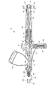
図1は、本発明のエアーブラシの全体の概略構成を示す断面図である。
図1に示すエアーブラシ10は、ほぼペンシルに似た形状をなすエアーブラシ本体20を具備している。すなわち、エアーブラシ本体20は、ほぼ直線状に延在する棒体をなし、ペンシルを握るようにして扱うことができるようになっている。
テーパ状に絞ったエアーブラシ本体20の先端部には塗料噴出ノズル30Aが取り付けられ、該塗料噴出ノズル30Aの後部の上部には塗料容器40が設けられている。
塗料容器40には液状の塗料(図示せず)が収納され、該塗料は塗料容器40の底面に形成された孔40Hを通して塗料噴出ノズル30A内に導かれるようになっている。なお、塗料噴出ノズル30Aの先端は塗料噴出孔30Hが形成され、この塗料噴出孔30Hは、通常時において、後述のニードル50の先端部によってシールされるようになっている。
FIG. 1 is a cross-sectional view showing an overall schematic configuration of the air brush of the present invention.
An
A
Liquid paint (not shown) is stored in the
また、エアーブラシ本体20の中間部の下部には、圧縮空気が供給される空気供給口部60が設けられている。この空気供給口部60は、たとえば圧縮空気の供給ホース(図示せず)を接続させる接続筒61からなり、その内部に給気バルブ62を備えている。給気バルブ62は、エアーブラシ本体20の空気供給口部60とは反対側の上部に設けられた操作杆70をエアーブラシ本体20側(図中α方向)へ押す操作によって開弁できるようになっている。
In addition, an air
操作杆70は、その先端部に枢軸71を介して押杆72を接続し、該押杆72を接続筒61の軸芯部に嵌装することにより、押し下げ自在に支持されている。
押杆72の先端は給気バルブ62に当接され、操作杆70の押し下げ操作によって給気バルブ62が開弁するようになっている。
そして、給気バルブ62の開弁によって、空気供給口部60から流入する圧縮空気は、エアーブラシ本体20内に形成された空気通路21、21’、21’’を通過して塗料噴出ノズル30Aの外周に沿って噴出するようになっている。
なお、塗料噴出ノズル30Aは、この塗料噴出ノズル30Aを囲むようにして空気噴出ノズル30Bが設けられ、圧縮空気は塗料噴出ノズル30Aと空気噴出ノズル30Bの間の隙間を通して噴出されるようになっている。そして、この明細書では、塗料噴出ノズル30Aと空気噴出ノズル30Bとを合せて、以下、単にノズル30と称する場合がある。
The
The tip end of the
When the
The
エアーブラシ本体20内には、ニードル50が軸芯部に沿ってスライド可能に配置され、このニードル50を操作杆70の操作によって後退させることができるようになっている。
すなわち、操作杆70は、枢軸71を中心に後方(図中β方向)へ傾動させることができ、この傾動によって、ニードル50およびニードルチャック51を後方へスライドできるようになっている。ニードルチャック51は、エアーブラシ本体20の後部の軸心部によって嵌装され、ニードル50を挿通によって支持している。
操作杆70の上述した操作により、塗料噴出ノズル30Aとニードル50とのシールが解除され、塗料容器40からの塗料を、空気噴出ノズル30Bからの圧縮空気の噴出とともに、塗料噴出ノズル30Aの塗料噴出孔30Hから吹き出すように構成されている。
In the air brush
That is, the operating
By the above-described operation of the operating
ここで、塗料噴出ノズル30Aの塗料噴出孔30Hのニードル50によるシールは、たとえば、ニードル50の先端部を塗料噴出ノズル30Aの塗料噴出孔30Hに抜き差し自在に貫通せしめる弁構造によって行っている。このため、塗料噴出孔30Hからニードル50が突出しているノズル30の先端部には、該ニードル50を保護するためのニードルキャップ80が備えられている。
ニードルキャップ80は、ノズル30(空気噴出ノズル30B)にたとえば螺合によって着脱自在に取付けられるようになっている。ニードルキャップ80は、通常時において、ノズル30に取り付けられているが、ペインティング等において、たとえば極細線を描く際に、ニードルキャップ80をノズル30から取り外し、該ノズル30の先端を被塗装面にできるだけ近づけて描くようにする場合がある。
Here, sealing by the
The
なお、ニードルチャック51は、コイルスプリング52を内包し、該コイルスプリング52の反発力によって常時前方に付勢されている。
また、ニードルチャック51の前端と操作杆70との間にはほぼS字状の作動板53が介在され、操作杆70を後方へ傾動させた場合に、作動板53を介してニードルチャック51およびニードル50を後方へスライドできるようになっている。
そして、エアーブラシ本体20の後端部にはニードルキャップ装着部90が形成されている。ここで、ニードルキャップ装着部90の説明に先立ち、ニードルキャップ80について詳述する。
The
Further, a substantially S-shaped
A needle
<ニードルキャップ80>
図2(a)、(b)は、エアーブラシ10のノズル30に着脱自在に取付けられるニードルキャップ80を示す斜視図である。
図2(a)は、ノズル30にニードルキャップ80が装着されている場合を示し、図2(b)は、ノズル30からニードルキャップ80を離脱させた場合を示している。
<
FIGS. 2A and 2B are perspective views showing a
2A shows a case where the
図2(a)、(b)から明らかとなるように、ニードルキャップ80は、ほぼ円筒形の部材からなっている。
上述したように、エアーブラシ10は、通常では、図2(a)に示すように、ノズル30にニードルキャップ80が装着された状態で使用されるようになっている。ノズル30の先端のニードル50を該ニードルキャップ80によって保護するためである。
しかし、ペインティング等において、たとえば極細線を描く際に、図2(b)に示すように、ニードルキャップ80をノズル30から取り外し、該ノズル30の先端を被塗装面にできるだけ近づけて描くようにする場合がある。
As is clear from FIGS. 2A and 2B, the
As described above, the
However, in drawing or the like, for example, when drawing an ultrathin line, as shown in FIG. 2B, the
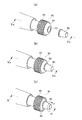
図3(a)は、図2(a)のIIIa−IIIa線における断面図を示し、図3(b)は、図2(b)のIIIb−IIIb線における断面図を示している。
図3(a)、(b)に示すように、ニードルキャップ80には、その内周に雌ねじ80Aが形成され、ノズル30には、その外周に雄ねじ30Cが形成されている。
ニードルキャップ80は、その雌ねじ80Aがノズル30の雄ねじ30Cに螺合することによって、ノズル30に装着されるようになっている(図3(a)参照)。そして、ニードルキャップ80は、その雌ねじ80Aがノズル30の雄ねじ30Cとの螺合を解除することによって、ノズル30から離脱されるようになっている(図3(b)参照)。
なお、ニードルキャップ80は、金属、あるいは樹脂のいずれで形成されていてもよい。
3A shows a cross-sectional view taken along the line IIIa-IIIa in FIG. 2A, and FIG. 3B shows a cross-sectional view taken along the line IIIb-IIIb in FIG. 2B.
As shown in FIGS. 3A and 3B, the
The
<ニードルキャップ装着部90>
図1に戻り、エアーブラシ本体20の後端部には、ニードルキャップ装着部90が形成されている。
図1において、ニードルキャップ装着部90は、エアーブラシ本体20の軸芯部に螺合された基台91を有し、この基台91の中心軸上に突出された突起部92が形成されている。突起部92の外周には雄ねじ92A(図5参照)が形成されている。この突起部92の雄ねじ92Aは、前記ニードルキャップ80の雌ねじ80Aが螺合されるようになっている。
なお、この基台91は、その中心軸に沿って孔91Hが形成され、この孔91Hにはニードル50が挿入されて支持されるようなっている。
また、基台91には突起部92との間に隙間を有し該突起部92を囲むようにして外側円筒体93が形成されている。そして、突起部92と外側円筒体93の間には、内側円筒体94が配置され、この内側円筒体94と基台91との間にはコイルスプリング95が配置されている。
<Needle
Returning to FIG. 1, a needle
In FIG. 1, the needle
The
An outer
ここで、内側円筒体94は、有底円筒体の底部の中心に孔94Aが形成された形状をなし、突起部92はそれに形成された棒体部92Pが有底円筒体の前記孔94Aおよび前記コイルスプリング95を貫通し、基台91に形成された前記孔91Hに挿入して固定されるようになっている。
これにより、内側円筒体94は、コイルスプリング95の反発力によって突起部92の雄ねじ92Aが形成された側面を隠すように配置されるようになっている。そして、内側円筒体94をコイルスプリング95の反発力に抗して基台91側に押すことによって、突起部92の雄ねじ92Aを内側円筒体94から露出させることができるようになっている。
Here, the inner
Thereby, the inner
図4(a)、(b)、(c)は、ニードルキャップ装着部90にニードルキャップ80が仮装着される手順を示した図である。
図4(a)は、ニードルキャップ80を装着させる前のニードルキャップ装着部90を示している。ニードルキャップ装着部90を構成する突起部92、内側円筒体94、および外側円筒体93は、それぞれの後端面においてほぼ滑らかに連続されて形成され、美観を考慮した曲面として構成されている。
図5(a)は、図4(a)のVa−Va線における断面を示す図であり、内側円筒体94は、コイルスプリング95によって突起部92の雄ねじ92Aが形成された側面を隠すように配置されている。
FIGS. 4A, 4 </ b> B, and 4 </ b> C are diagrams illustrating a procedure in which the
FIG. 4A shows the needle
5A is a view showing a cross section taken along the line Va-Va of FIG. 4A, and the inner
図4(b)は、ニードルキャップ80を突起部92に螺合させる直前のニードルキャップ装着部90を示している。ニードルキャップ80の一端は、突起部92を被って、内側円筒体94に当接されている。
図5(b)は、図4(b)のVb−Vb線における断面を示す図であり、突起部92とニードルキャップ80は同軸上に配置されている。
FIG. 4B shows the needle
FIG. 5B is a view showing a cross section taken along the line Vb-Vb in FIG. 4B, and the
図4(c)は、ニードルキャップ80をその軸周り(図中γ方向)に回転させている状態のニードルキャップ装着部90を示している。これにより、突起部92の雄ねじ92Aとニードルキャップ80の雌ねじ80Aは螺合し始めるとともに、ニードルキャップ80は、内側円筒体94をコイルスプリング95の反発力に抗して押し始めるようになる。これにより、ニードルキャップ80の突起部92への螺合がなされ、該ニードルキャップ80はニードルキャップ装着部90に仮装着されるようになる。
図6は、図4(c)のVI−VI線における断面を示す斜視図であり、ニードルキャップ80は、その雌ねじ80Aが突起部92の雄ねじ92Aに螺合されていることが明らかになる。
FIG. 4C shows the needle
FIG. 6 is a perspective view showing a cross section taken along line VI-VI in FIG. 4C, and it becomes clear that the
上述したことから明らかになるように、本発明のエアーブラシ10によれば、ノズル30から取り外したニードルキャップ80を、即、ニードルキャップ装着部90に、簡単に仮装着させることができることから、紛失し難くすることができるようになる。
As will be apparent from the above, according to the
(実施形態2)
実施形態1では、ニードルキャップ80は、ノズル30に螺合によって取り付けられ、ニードルキャップ装着部90に螺合によって仮装着されたものである。しかし、このような螺合に限定されることはなく、嵌合によって取付け、あるいは仮装着できるように構成してもよいことはもちろんである。
図7(a)、(b)、(c)は、このように構成した実施形態2のエアーブラシの説明図である。
図7(a)は、図3(a)に対応する図であり、ノズル30から外したニードルキャップ80の内周面の後端部にはその内周に沿って凸部101が形成されている。これにより、ニードルキャップ80の内周面の先端側には凹部101Aが形成されるようになる。また、ノズル30の外周面にはその外周に沿って凹部102が形成されている。これにより、ノズル30の該凹部102より先端側の外周面には凸部102Aが形成されるようになる。ニードルキャップ80のノズル30に対する取付けは、ニードルキャップ80の凸部101、凹部101Aが、それぞれ、ノズル30の凹部102、凸部102Aに嵌合することによってなされるようになっている。
図7(b)は、図5(a)に対応する図であり、ニードルキャップ装着部90の突起部92の外周面の先端側にはその外周に沿って凹部103が形成されている。これにより、突起部92の内周面の後端部には凸部103Aが形成されるようになる。突起部92の凹部103、凸部103Aは、通常において、コイルスプリング95の付勢力によって移動する内側円筒体94に隠されるようになるのは、図5(b)の場合と同様である。
図7(c)は、図5(b)に対応する図であり、ノズル30から外したニードルキャップ80をニードルキャップ装着部90に仮装着させた場合を示した図である。図7(c)に示すように、ニードルキャップ80のニードルキャップ装着部90に対する仮装着は、内側円筒体94のコイルスプリング95に抗する移動によって、突起部92の外周面に形成された凸部103A、凹部103を露出させ、ニードルキャップ80の凸部101、凹部101Aが、それぞれ、ニードルキャップ装着部90の突起部92の凹部103、凸部103Aに嵌合することによってなされるようになっている。
(Embodiment 2)
In the first embodiment, the
FIGS. 7A, 7B, and 7C are explanatory views of the air brush of the second embodiment configured as described above.
FIG. 7A is a view corresponding to FIG. 3A, and a
FIG. 7B is a diagram corresponding to FIG. 5A, and a
FIG. 7C is a view corresponding to FIG. 5B, and shows a case where the
(実施形態3)
実施形態2では、ニードルキャップ装着部90において、コイルスプリング95、内側円筒体94を設けるようにしたものである。しかし、これに限定されることはなく、該コイルスプリング95、内側円筒体94を除いた構成とするようにしてもよい。
図8(a)は、図7(b)に対応し、図8(b)は、図7(c)に対応した図である。図8(a)、(b)に示すように、図7(b)、(c)と比べて、コイルスプリング95、内側円筒体94がない構成となっている。そして、その他の構成は、図7(b)、(c)と同様となっている。
(Embodiment 3)
In the second embodiment, the needle
FIG. 8A corresponds to FIG. 7B, and FIG. 8B corresponds to FIG. 7C. As shown in FIGS. 8A and 8B, the
(実施形態4)
実施形態1ないし実施形態3では、ニードルキャップ80のノズル30およびニードルキャップ装着部90への取付けおよび仮装着は、螺合、あるいは嵌合で行ったものである。しかし、これらに限定されることはなく、磁石の吸着によって行ってもよいことはもちろんである。
図9(a)、(b)は、それぞれ、図8(a)、(b)に対応した図である。図9(a)、(b)に示すように、ニードルキャップ装着部90の突起部92は、磁性体(磁石)で形成され、その表面はたとえばN(S)極となっている。なお、図示していないが、ノズル30(図1参照)においても磁性体(磁石)で形成され、その表面はN(S)極となっている。一方、ニードルキャップ80は、磁性体(磁石)で形成され、その内周面はたとえばS(N)極となっている。
このようにした場合、ニードルキャップ80、ノズル30、ニードルキャップ装着部90に特別の工夫を凝らすことなく、ニードルキャップ80のノズル30およびニードルキャップ装着部90への取付けおよび仮装着を信頼性よく行うことができるようになる。
この場合、ニードルキャップ80、ノズル30、ニードルキャップ装着部90は磁石で構成されている必要はなく、その一部として形成されていてもよいことはもちろんである。
そして、このような磁石によるニードルキャップ80のノズル30およびニードルキャップ装着部90への取付けおよび仮装着は、実施形態1、2の構成において適用させることができる。
(Embodiment 4)
In the first to third embodiments, the
FIGS. 9A and 9B correspond to FIGS. 8A and 8B, respectively. As shown in FIGS. 9A and 9B, the
In such a case, the
In this case, the
The attachment and temporary mounting of the
(実施形態5)
実施形態1ないし4では、いわゆるペンシル型と称され、操作杆を備えるエアーブラシについて説明したものである。しかし、これに限定されることはなく、たとえばガン型と称され、該操作杆に替えて引金を備えたエアーブラシにも適用できることはいうまでもない。
(Embodiment 5)
In the first to fourth embodiments, a so-called pencil type is described, and an air brush having an operation rod is described. However, the present invention is not limited to this. For example, it is called a gun type, and it goes without saying that it can be applied to an air brush provided with a trigger instead of the operation rod.
以上、実施形態を用いて本発明を説明したが、本発明の技術的範囲は上記実施形態に記載の範囲には限定されないことは言うまでもない。上記実施形態に、多様な変更または改良を加えることが可能であることが当業者に明らかである。また、その様な変更または改良を加えた形態も本発明の技術的範囲に含まれ得ることが、特許請求の範囲の記載から明らかである。 As mentioned above, although this invention was demonstrated using embodiment, it cannot be overemphasized that the technical scope of this invention is not limited to the range as described in the said embodiment. It will be apparent to those skilled in the art that various modifications or improvements can be added to the above-described embodiments. Further, it is apparent from the description of the scope of claims that embodiments with such changes or improvements can also be included in the technical scope of the present invention.
10……エアーブラシ、
20……エアーブラシ本体、
21、21’、21’’……空気通路、
30……ノズル、
30A……塗料噴出ノズル、
30B……空気噴出ノズル、
30H……塗料噴出孔、
40……塗料容器、
50……ニードル、
51……ニードルチャック、
52……コイルスプリング、
53……作動板、
60……空気供給口部、
61……接続筒、
62……給気バルブ、
70……操作杆、
71……枢軸、
72……押杆、
80……ニードルキャップ、
90……ニードルキャップ装着部、
91……基台、
92……突起部、
92P……棒体部、
93……外側円筒体、
94……内側円筒体、
95……コイルスプリング。
101……凸部、
102、103……凹部、
10 …… Air brush,
20 …… Air brush body,
21, 21 ', 21''…… Air passage,
30 …… Nozzle,
30A: Paint spray nozzle,
30B …… Air jet nozzle,
30H: Paint spray hole,
40 …… Paint container,
50 …… Needle,
51 …… Needle chuck,
52 …… Coil spring,
53 …… Operating plate,
60 …… Air supply port,
61 …… Connection tube,
62 …… Air supply valve,
70 …… Operation 杆
71 …… Axis,
72 ....
80 …… needle cap,
90 …… Needle cap mounting part,
91 …… Base,
92 …… Protrusions,
92P ... Rod body part,
93 …… Outer cylinder,
94 …… Inner cylinder,
95 …… Coil spring.
101 …… Convex part,
102, 103 ...... concave,
Claims (8)
前記エアーブラシ本体の先端に設けられ、塗料流と空気流を噴出させるノズルと、
前記ノズルに着脱自在に取付けられるニードルキャップと、
前記エアーブラシ本体の後端に設けられ、前記ノズルから離脱させた前記ニードルキャップを仮装着させるニードルキャップ装着部と、
を有することを特徴とするエアーブラシ。 The airbrush body,
A nozzle provided at the tip of the airbrush main body, and ejecting a paint flow and an air flow;
A needle cap removably attached to the nozzle;
A needle cap mounting portion that is provided at a rear end of the air brush body and temporarily mounts the needle cap detached from the nozzle;
An air brush characterized by comprising:
前記突起部は、その外周に前記ニードルキャップの前記雌ねじに螺合される雄ねじを有することを特徴とする請求項2に記載のエアーブラシ。 The needle cap has an internal thread that is threadedly engaged with an external thread formed on the outer periphery of the nozzle on the inner periphery thereof,
The air brush according to claim 2, wherein the protrusion has an external thread that is screwed onto the external thread of the needle cap on an outer periphery thereof.
さらに、
前記突起部を囲んで形成される外側円筒体と、
前記外側円筒体と前記突起部との間に配置される内側円筒体と、
前記エアーブラシ本体と前記内側円筒体との間に配置されたコイルスプリングと、
を有し、
前記内側円筒体は、前記コイルスプリングの付勢力に抗してエアーブラシ本体側へ押すことにより、前記突起部の雄螺子を露出できることを特徴とする請求項3に記載のエアーブラシ。 The needle cap mounting part is
further,
An outer cylindrical body formed surrounding the protrusion,
An inner cylindrical body disposed between the outer cylindrical body and the protrusion;
A coil spring disposed between the airbrush body and the inner cylindrical body;
Have
4. The air brush according to claim 3, wherein the inner cylindrical body can expose the male screw of the protrusion by being pushed toward the air brush main body against the urging force of the coil spring.
前記突起部は、その外周に前記ニードルキャップの前記凸部に嵌合される凹部を有することを特徴とする請求項2に記載のエアーブラシ。 The needle cap has a convex part fitted in a concave part formed on the outer periphery of the nozzle on the inner periphery thereof,
The air brush according to claim 2, wherein the protrusion has a recess fitted to the protrusion of the needle cap on an outer periphery thereof.
さらに、
前記突起部を囲んで形成される外側円筒体と、
前記外側円筒体と前記突起部との間に配置される内側円筒体と、
前記エアーブラシ本体と前記内側円筒体との間に配置されたコイルスプリングと、
を有し、
前記内側円筒体を、前記コイルスプリングの付勢力に抗してエアーブラシ本体側へ押すことにより、前記突起部の前記凹部およびその周辺の凸部を露出できることを特徴とする請求項5に記載のエアーブラシ。 The needle cap mounting part is
further,
An outer cylindrical body formed surrounding the protrusion,
An inner cylindrical body disposed between the outer cylindrical body and the protrusion;
A coil spring disposed between the airbrush body and the inner cylindrical body;
Have
The said recessed part of the said projection part and the convex part of the circumference | surroundings can be exposed by pushing the said inner side cylindrical body to the airbrush main body side against the urging | biasing force of the said coil spring. Air brush.
前記磁石は、前記ノズル及び前記ニードルキャップ装着部の取り付け側がN極又はS極のいずれか一方の磁極によって形成され、
前記ノズルは前記ニードルキャップの磁石の磁極とは反対の磁極で形成され、
前記ニードルキャップ装着部は前記ニードルキャップの磁石の磁極とは反対の磁極で形成されることを特徴とする請求項1に記載のエアーブラシ。 The needle cap includes a magnet,
The magnet, the mounting side of the nozzle and the needle cap mounting portion is formed by one of the magnetic poles of N pole or S pole,
The nozzle is formed with a magnetic pole opposite to the magnetic pole of the needle cap magnet,
The air brush according to claim 1, wherein the needle cap mounting portion is formed with a magnetic pole opposite to a magnetic pole of the magnet of the needle cap.
前記ノズルは鉄などの磁性体によって形成され、
前記ニードルキャップ装着部は鉄などの磁性体によって形成されることを特徴とする請求項1に記載のエアーブラシ。 The needle cap includes a magnet, and the magnet is formed by either the N pole or the S pole on the mounting side of the nozzle and the needle cap mounting portion.
The nozzle is formed of a magnetic material such as iron,
The air brush according to claim 1, wherein the needle cap mounting portion is formed of a magnetic material such as iron.
Priority Applications (3)
| Application Number | Priority Date | Filing Date | Title |
|---|---|---|---|
| JP2013102602A JP6132396B2 (en) | 2013-05-14 | 2013-05-14 | Air brush |
| US14/274,993 US9555424B2 (en) | 2013-05-14 | 2014-05-12 | Airbrush |
| EP14168145.2A EP2803421B1 (en) | 2013-05-14 | 2014-05-13 | Airbrush gun |
Applications Claiming Priority (1)
| Application Number | Priority Date | Filing Date | Title |
|---|---|---|---|
| JP2013102602A JP6132396B2 (en) | 2013-05-14 | 2013-05-14 | Air brush |
Publications (2)
| Publication Number | Publication Date |
|---|---|
| JP2014221468A true JP2014221468A (en) | 2014-11-27 |
| JP6132396B2 JP6132396B2 (en) | 2017-05-24 |
Family
ID=50687379
Family Applications (1)
| Application Number | Title | Priority Date | Filing Date |
|---|---|---|---|
| JP2013102602A Active JP6132396B2 (en) | 2013-05-14 | 2013-05-14 | Air brush |
Country Status (3)
| Country | Link |
|---|---|
| US (1) | US9555424B2 (en) |
| EP (1) | EP2803421B1 (en) |
| JP (1) | JP6132396B2 (en) |
Cited By (2)
| Publication number | Priority date | Publication date | Assignee | Title |
|---|---|---|---|---|
| JP2017087195A (en) * | 2015-11-17 | 2017-05-25 | 藤倉化成株式会社 | Spray gun and groove coating method |
| WO2017191788A1 (en) * | 2016-05-05 | 2017-11-09 | 丈洋 熊谷 | Airbrush enabling pencil-like hold thereof |
Families Citing this family (5)
| Publication number | Priority date | Publication date | Assignee | Title |
|---|---|---|---|---|
| EP3103628B1 (en) | 2015-06-11 | 2020-08-12 | Walmec S.P.A. | Spray gun |
| CN204996622U (en) * | 2015-09-23 | 2016-01-27 | 奉化市必达机械制造有限公司 | Hydrocone type spraying pen |
| IT201800009634A1 (en) | 2018-10-19 | 2020-04-19 | Walmec Spa | Improved Paint Tank |
| IT201800010567A1 (en) | 2018-11-26 | 2020-05-26 | Walmec Spa | Sprayable product tank to feed an airbrush |
| CN112588489A (en) * | 2020-12-19 | 2021-04-02 | 咸阳职业技术学院 | Paint spraying manipulator for production and processing of automobile parts |
Citations (6)
| Publication number | Priority date | Publication date | Assignee | Title |
|---|---|---|---|---|
| JP2006524595A (en) * | 2003-04-28 | 2006-11-02 | サンフォード エル.ピー. | Writing assembly with eraser assembly |
| US7246757B2 (en) * | 2005-05-02 | 2007-07-24 | Victor Air Tools Co., Ltd. | Nozzle cover of air brush |
| US20080265057A1 (en) * | 2007-04-26 | 2008-10-30 | Phillip John Martin | Handheld device and method for clearing obstructions from spray nozzles |
| US20090297250A1 (en) * | 2008-05-28 | 2009-12-03 | Bon Artek Writing Industry Co., Ltd. | Pen cap and pen barrel coupling structure |
| JP2010052326A (en) * | 2008-08-29 | 2010-03-11 | Pilot Corporation | Cap-type writing instrument |
| WO2012150406A1 (en) * | 2011-05-02 | 2012-11-08 | Qualipac | Packaging device including an adjustable magnetic closure system |
Family Cites Families (4)
| Publication number | Priority date | Publication date | Assignee | Title |
|---|---|---|---|---|
| US2460529A (en) * | 1944-06-05 | 1949-02-01 | Jens A Paasche | Airbrush |
| JP3083285B2 (en) | 1998-11-11 | 2000-09-04 | 株式会社ビービーリッチ | Air brush |
| US6960039B2 (en) | 2003-05-20 | 2005-11-01 | Overbreak, L.L.C. | Drawing tool for using multiple markers |
| US8882000B2 (en) | 2011-02-25 | 2014-11-11 | Je Matadi, Inc. | Air brush |
-
2013
- 2013-05-14 JP JP2013102602A patent/JP6132396B2/en active Active
-
2014
- 2014-05-12 US US14/274,993 patent/US9555424B2/en active Active
- 2014-05-13 EP EP14168145.2A patent/EP2803421B1/en active Active
Patent Citations (6)
| Publication number | Priority date | Publication date | Assignee | Title |
|---|---|---|---|---|
| JP2006524595A (en) * | 2003-04-28 | 2006-11-02 | サンフォード エル.ピー. | Writing assembly with eraser assembly |
| US7246757B2 (en) * | 2005-05-02 | 2007-07-24 | Victor Air Tools Co., Ltd. | Nozzle cover of air brush |
| US20080265057A1 (en) * | 2007-04-26 | 2008-10-30 | Phillip John Martin | Handheld device and method for clearing obstructions from spray nozzles |
| US20090297250A1 (en) * | 2008-05-28 | 2009-12-03 | Bon Artek Writing Industry Co., Ltd. | Pen cap and pen barrel coupling structure |
| JP2010052326A (en) * | 2008-08-29 | 2010-03-11 | Pilot Corporation | Cap-type writing instrument |
| WO2012150406A1 (en) * | 2011-05-02 | 2012-11-08 | Qualipac | Packaging device including an adjustable magnetic closure system |
Cited By (2)
| Publication number | Priority date | Publication date | Assignee | Title |
|---|---|---|---|---|
| JP2017087195A (en) * | 2015-11-17 | 2017-05-25 | 藤倉化成株式会社 | Spray gun and groove coating method |
| WO2017191788A1 (en) * | 2016-05-05 | 2017-11-09 | 丈洋 熊谷 | Airbrush enabling pencil-like hold thereof |
Also Published As
| Publication number | Publication date |
|---|---|
| JP6132396B2 (en) | 2017-05-24 |
| EP2803421A1 (en) | 2014-11-19 |
| US9555424B2 (en) | 2017-01-31 |
| US20140339338A1 (en) | 2014-11-20 |
| EP2803421B1 (en) | 2017-02-08 |
Similar Documents
| Publication | Publication Date | Title |
|---|---|---|
| JP6132396B2 (en) | Air brush | |
| EP3508279B1 (en) | Air cap arrangement and spray gun | |
| US8096489B2 (en) | Spraying device apparatus | |
| US10835911B2 (en) | Trigger for a spray gun and spray gun having same | |
| ES2234074T3 (en) | CONVERTIBLE SPRAY GUN. | |
| JP5787407B2 (en) | Spray gun | |
| JPH09276756A (en) | Air brush | |
| JP6427785B2 (en) | Nebulizer | |
| WO2015141244A1 (en) | Atomizer | |
| JP5618925B2 (en) | Paint spray gun filter and paint spray gun using the same | |
| JP6233861B1 (en) | Nebulizer | |
| JP2013013842A6 (en) | Paint spray gun filter and paint spray gun using the same | |
| JP6191990B2 (en) | Makeup sprayer | |
| JP6427784B2 (en) | Nebulizer | |
| CN210545781U (en) | Spray pen | |
| JP2014136177A (en) | Spray gun for electrostatic coating | |
| JPH0230041Y2 (en) | ||
| KR102098521B1 (en) | An eyeliner equipped with a cap with a built-in hollow cosmetic ink storing member | |
| JP2006015218A (en) | Air brush for coating | |
| JP2016203300A (en) | Tool with marking function | |
| JP2000079360A (en) | Penholder in airbrush | |
| JP2005279563A (en) | Trigger type liquid injector | |
| JP2014177065A (en) | Direct liquid type coating tool | |
| JP2015127057A (en) | Spray gun | |
| JP2008132455A (en) | Atomizer and atomizing cartridge |
Legal Events
| Date | Code | Title | Description |
|---|---|---|---|
| A621 | Written request for application examination |
Free format text: JAPANESE INTERMEDIATE CODE: A621 Effective date: 20160411 |
|
| A977 | Report on retrieval |
Free format text: JAPANESE INTERMEDIATE CODE: A971007 Effective date: 20170119 |
|
| A131 | Notification of reasons for refusal |
Free format text: JAPANESE INTERMEDIATE CODE: A131 Effective date: 20170131 |
|
| A521 | Request for written amendment filed |
Free format text: JAPANESE INTERMEDIATE CODE: A523 Effective date: 20170330 |
|
| TRDD | Decision of grant or rejection written | ||
| A01 | Written decision to grant a patent or to grant a registration (utility model) |
Free format text: JAPANESE INTERMEDIATE CODE: A01 Effective date: 20170404 |
|
| A61 | First payment of annual fees (during grant procedure) |
Free format text: JAPANESE INTERMEDIATE CODE: A61 Effective date: 20170414 |
|
| R150 | Certificate of patent or registration of utility model |
Ref document number: 6132396 Country of ref document: JP Free format text: JAPANESE INTERMEDIATE CODE: R150 |
|
| R250 | Receipt of annual fees |
Free format text: JAPANESE INTERMEDIATE CODE: R250 |
|
| R250 | Receipt of annual fees |
Free format text: JAPANESE INTERMEDIATE CODE: R250 |
|
| R250 | Receipt of annual fees |
Free format text: JAPANESE INTERMEDIATE CODE: R250 |
|
| R250 | Receipt of annual fees |
Free format text: JAPANESE INTERMEDIATE CODE: R250 |