JP2014217618A - Beauty device - Google Patents

Beauty device Download PDF

Info

Publication number
JP2014217618A
JP2014217618A JP2013099309A JP2013099309A JP2014217618A JP 2014217618 A JP2014217618 A JP 2014217618A JP 2013099309 A JP2013099309 A JP 2013099309A JP 2013099309 A JP2013099309 A JP 2013099309A JP 2014217618 A JP2014217618 A JP 2014217618A
Authority
JP
Japan
Prior art keywords
heat
heat transfer
supply body
cold
heat supply
Prior art date
Legal status (The legal status is an assumption and is not a legal conclusion. Google has not performed a legal analysis and makes no representation as to the accuracy of the status listed.)
Granted
Application number
JP2013099309A
Other languages
Japanese (ja)
Other versions
JP6139967B2 (en
Inventor
岡本 祐介
Yusuke Okamoto
祐介 岡本
Current Assignee (The listed assignees may be inaccurate. Google has not performed a legal analysis and makes no representation or warranty as to the accuracy of the list.)
Maxell Ltd
Original Assignee
Hitachi Maxell Ltd
Priority date (The priority date is an assumption and is not a legal conclusion. Google has not performed a legal analysis and makes no representation as to the accuracy of the date listed.)
Filing date
Publication date
Application filed by Hitachi Maxell Ltd filed Critical Hitachi Maxell Ltd
Priority to JP2013099309A priority Critical patent/JP6139967B2/en
Publication of JP2014217618A publication Critical patent/JP2014217618A/en
Application granted granted Critical
Publication of JP6139967B2 publication Critical patent/JP6139967B2/en
Active legal-status Critical Current
Anticipated expiration legal-status Critical

Links

Images

Classifications

    • AHUMAN NECESSITIES
    • A61MEDICAL OR VETERINARY SCIENCE; HYGIENE
    • A61FFILTERS IMPLANTABLE INTO BLOOD VESSELS; PROSTHESES; DEVICES PROVIDING PATENCY TO, OR PREVENTING COLLAPSING OF, TUBULAR STRUCTURES OF THE BODY, e.g. STENTS; ORTHOPAEDIC, NURSING OR CONTRACEPTIVE DEVICES; FOMENTATION; TREATMENT OR PROTECTION OF EYES OR EARS; BANDAGES, DRESSINGS OR ABSORBENT PADS; FIRST-AID KITS
    • A61F7/00Heating or cooling appliances for medical or therapeutic treatment of the human body

Landscapes

  • Thermotherapy And Cooling Therapy Devices (AREA)
  • Health & Medical Sciences (AREA)
  • Engineering & Computer Science (AREA)
  • Biomedical Technology (AREA)
  • Heart & Thoracic Surgery (AREA)
  • Vascular Medicine (AREA)
  • Life Sciences & Earth Sciences (AREA)
  • Animal Behavior & Ethology (AREA)
  • General Health & Medical Sciences (AREA)
  • Public Health (AREA)
  • Veterinary Medicine (AREA)

Abstract

PROBLEM TO BE SOLVED: To provide a beauty device which simultaneously gives thermal stimulation at different temperatures on the center part and its peripheral part of a skin surface touched by a skin treatment head with little time and labor, and gives thermal stimulation at temperatures different from one another on the skin surface around the eyeball and the eyelid when structured as an eye care beauty device to exhibit beauty effect around eye parts.SOLUTION: A skin treatment head 2 includes: hot heat generation means 13 and cold heat generation means 14; a first heat-supplying body 30 conducting heat generated by the hot heat generation means 13 or the cold heat generation means 14 to a skin surface; and a second heat-supplying body 20 conducting heat generated by the cool heat generation means 14 or the hot heat generation means 13 to the skin surface. The second heat-supplying body 20 is arranged in a state of surrounding a periphery of the first heat-supplying body 30.

Description

本発明は、肌面に対して異なる温度の熱刺激を付与できる肌処理ヘッドを備えた美容機器に関する。美容機器は例えば目元ケア用の美容機器として使用することができる。   The present invention relates to a beauty device including a skin treatment head that can apply thermal stimulation at different temperatures to the skin surface. The beauty device can be used as a beauty device for eye care, for example.

肌面に冷熱刺激または温熱刺激を与える美容機器は、例えば特許文献1の冷温美顔器に開示されている。そこでは、本体部の一側面に、ペルチェ素子で冷却される冷熱部と、ヒーターで加熱される温熱部とが左右に隣接する状態で設けてある。冷熱部および温熱部の各面は、互いの面が所定の角度で交わるように配設されている。使用時には、冷熱部と温熱部とを肌面に交互に接触させて、冷熱刺激と温熱刺激を肌面に与える。   A beauty device for applying cold stimulation or thermal stimulation to the skin surface is disclosed in, for example, a cold and warm facial device disclosed in Patent Document 1. There, a cooling unit cooled by a Peltier element and a heating unit heated by a heater are provided on one side of the main body in a state adjacent to the left and right. The surfaces of the cold and hot portions are arranged such that the surfaces intersect at a predetermined angle. At the time of use, a cold part and a warm part are made to contact a skin surface alternately, and a cold stimulus and a thermal stimulus are given to the skin surface.

目元に冷熱刺激を与える美容機器は、例えば特許文献2の人体冷却器に開示されている。そこでは、左右一対の熱伝導手段が、ケース本体のインナーケースの外部に露出するように配設されており、熱伝導手段には、それぞれペルチェ素子が面接触状に配置されている。ケース本体には、頭部を抱持するバンドが着脱可能に設けられている。ペルチェ素子で発生した温熱は、放熱板に伝導し、ケース本体内に設けた冷却ファンにより、アウターケースに形成した開口部からケース本体の外部に排出される。使用時には、熱伝導手段がまぶたの肌面に密着するようにバンドでケース本体を頭部に装着して、ペルチェ素子を駆動することにより、冷熱刺激をまぶたの肌面に与える。   A beauty device that gives cold stimulation to the eyes is disclosed in, for example, the human body cooler of Patent Document 2. In this case, a pair of left and right heat conduction means are arranged so as to be exposed to the outside of the inner case of the case body, and Peltier elements are arranged in surface contact with the heat conduction means. The case body is provided with a detachable band for holding the head. The heat generated in the Peltier element is conducted to the heat radiating plate, and is discharged to the outside of the case body from the opening formed in the outer case by the cooling fan provided in the case body. At the time of use, the case body is attached to the head with a band so that the heat conducting means is in close contact with the skin surface of the eyelid, and the Peltier element is driven to apply a cold stimulus to the skin surface of the eyelid.

また、目元に温熱刺激を与える美容機器は、例えば特許文献3の目元ケア装置に開示されている。そこでは、目の周りを覆う一対の凹所を備えたゴーグル状のハウジングと、凹所の内奥に配置される水保持部と、ハウジングに埋設されて水保持部を加熱する加熱部などで美容機器を構成している。ハウジングの下縁寄りの左右には、下まぶたの周辺を加熱する第2の加熱部が設けてある。使用時には、スポンジ状の水保持部に水を含浸させ、バンドを後頭部に掛けてハウジングを顔面に密着させ、目元の周囲を凹所で覆う。この状態で、加熱部のヒーターに通電し、ヒーターの熱で水保持部の水を気化させ、凹所に充満する水蒸気で温熱刺激を目の周囲の皮膚や筋肉に与える。   A beauty device that gives thermal stimulation to the eyes is disclosed in, for example, an eye care device disclosed in Patent Document 3. There, a goggle-shaped housing provided with a pair of recesses that cover the eyes, a water holding part disposed inside the recess, a heating part that is embedded in the housing and heats the water holding part, etc. Make up beauty equipment. On the left and right sides near the lower edge of the housing, a second heating unit for heating the periphery of the lower eyelid is provided. In use, a sponge-like water holding part is impregnated with water, a band is hung on the back of the head, the housing is closely attached to the face, and the area around the eyes is covered with a recess. In this state, the heater of the heating unit is energized, the water of the water holding unit is vaporized by the heat of the heater, and thermal stimulation is given to the skin and muscles around the eyes with water vapor filling the recess.

特開昭63−257556号公報(第3頁左上欄、図7)JP 63-257556 A (page 3, upper left column, FIG. 7) 特開平11−128261号公報(段落番号0018、0021、0023、図2、図6)JP 11-128261 A (paragraph numbers 0018, 0021, 0023, FIG. 2, FIG. 6) 特開2011−045394号公報(段落番号0031〜0033、図2)JP 2011-045394 A (paragraph numbers 0031 to 0033, FIG. 2)

特許文献1の美容機器では、冷熱部および温熱部の各面が、本体の一側面に隣接させてあるので、本体の傾きを変更するだけで、肌面にそれぞれの面を交互に接触させて、冷熱と温熱の刺激を交互に与えることができる。また、肌面に冷熱部および温熱部の両面を同時に接触させた状態で、各面が隣接する方向に本体を移動させることにより、各面の移動方向の肌面に対して、順次冷熱と温熱を連続して交互に与えることができる。しかし、本体を垂直に移動させた場合には、各面の移動方向の肌面に対して、いずれか一方の刺激のみを連続して与えるだけである。また、円を描くように本体部を移動させた場合には、冷熱と温熱とが与えられる部分と、冷熱と温熱とのいずれか一方のみが与えられる部分とが発生し、肌面に対して均一に両熱刺激を与えることができない。   In the beauty device of Patent Document 1, each surface of the cooling unit and the heating unit is adjacent to one side surface of the main body. Therefore, by simply changing the inclination of the main body, the respective surfaces are alternately brought into contact with the skin surface. , Cold and warm stimulation can be given alternately. In addition, with both surfaces of the cold and hot parts in contact with the skin surface at the same time, by moving the body in the direction where each face is adjacent, the heat and heat are sequentially applied to the skin surface in the moving direction of each face. Can be given alternately in succession. However, when the main body is moved vertically, only one of the stimuli is continuously applied to the skin surface in the moving direction of each surface. In addition, when the main body is moved so as to draw a circle, a portion to which cold and warm heat is given and a portion to which only one of cold and warm heat is given occur, and the skin surface It is impossible to give both heat stimuli uniformly.

特許文献2および3の美容機器では、目元部分の肌面に冷熱あるいは温熱のいずれか一方の刺激しか与えることができない点に改良の余地がある。   In the beauty devices of Patent Documents 2 and 3, there is room for improvement in that only one of cold heat and warm heat can be applied to the skin surface of the eye area.

本発明の目的は、肌処理ヘッドを接触させた肌面の中央部とその周囲部とに、少ない手間で同時に異なる温度の熱刺激を与えることができる美容機器を提供することにある。
本発明の目的は、広範囲の肌面に対して熱刺激を与える場合でも、肌処理ヘッドの姿勢を変更することなく、肌面に対して簡便に異なる温度の熱刺激を交互に与えることができる美容機器を提供することにある。
本発明の目的は、眼球とまぶたの周辺の肌面に、それぞれ異なる温度の熱刺激を与えて目元部分に美容効果を発揮することができる目元ケア用の美容機器を提供することにある。
An object of the present invention is to provide a beauty device capable of simultaneously applying thermal stimuli at different temperatures to a central portion of a skin surface and a peripheral portion thereof in contact with a skin treatment head with little effort.
An object of the present invention is to provide thermal stimulation of different temperatures simply and alternately to the skin surface without changing the posture of the skin treatment head even when thermal stimulation is applied to a wide range of skin surfaces. To provide beauty equipment.
An object of the present invention is to provide a cosmetic device for eye care that can exert a cosmetic effect on the eye area by applying thermal stimulation at different temperatures to the skin surface around the eyeball and the eyelid.

本発明に係る美容機器は、肌処理ヘッド2に、温熱生成手段13および冷熱生成手段14と、温熱生成手段13または冷熱生成手段14で生成された熱を肌面に伝導する第1熱供給体30と、冷熱生成手段14または温熱生成手段13で生成された熱を肌面に伝導する第2熱供給体20とが設けられている。第2熱供給体20が、第1熱供給体30の周囲を囲む状態で配置してあることを特徴とする。なお、本発明における温熱生成手段13および冷熱生成手段14における「温熱」および「冷熱」とは、人の感覚を基準にした温熱あるいは冷熱ではなく、異なる温度のうち温度が高い側を温熱とし、温度が低い側を冷熱とする相対的な概念である。   The beauty device according to the present invention includes a first heat supply body that conducts heat generated by the heat generation means 13 and the cold heat generation means 14 to the skin treatment head 2 to the skin surface. 30 and a second heat supply body 20 that conducts heat generated by the cold heat generating means 14 or the hot heat generating means 13 to the skin surface. The second heat supply body 20 is arranged so as to surround the first heat supply body 30. In the present invention, the “heat” and “cold heat” in the heat generation means 13 and the cold heat generation means 14 are not the heat or cold based on human sense, but the higher temperature side of the different temperatures is the heat, It is a relative concept that the cold side is the low temperature side.

第2熱供給体20を、肌面との接触部分の側へ向かって開口するカップ形状に形成する。   The 2nd heat supply body 20 is formed in the cup shape opened toward the contact part side with a skin surface.

第2熱供給体20は、ベース壁21と、ベース壁21に連続して形成される湾曲壁22とを備えている。湾曲壁22を、カップ開口縁へ向かって徐々に拡開するラッパ状に形成する。   The second heat supply body 20 includes a base wall 21 and a curved wall 22 formed continuously with the base wall 21. The curved wall 22 is formed in a trumpet shape that gradually expands toward the cup opening edge.

第1熱供給体30に肌面と接触する第1伝熱面34を設ける。第1伝熱面34を、第2熱供給体20のカップ開口縁の第2伝熱面23よりカップ内奥側へ凹んだ位置に配置する。   The first heat supply body 30 is provided with a first heat transfer surface 34 that comes into contact with the skin surface. The first heat transfer surface 34 is disposed at a position recessed from the second heat transfer surface 23 at the cup opening edge of the second heat supply body 20 toward the inner side of the cup.

温熱生成手段13または冷熱生成手段14と第1熱供給体30とを、第1伝熱体37を介して熱移動可能に接続する。冷熱生成手段14または温熱生成手段13と第2熱供給体20とを、第2伝熱体24を介して熱移動可能に接続する。第1伝熱体37と第2伝熱体24との間に、両伝熱体37・24の間の熱移動を阻止するスペーサー46を配置する。   The hot heat generating means 13 or the cold heat generating means 14 and the first heat supply body 30 are connected via the first heat transfer body 37 so as to be capable of transferring heat. The cold heat generating means 14 or the warm heat generating means 13 and the second heat supply body 20 are connected via the second heat transfer body 24 so as to be able to transfer heat. A spacer 46 is disposed between the first heat transfer body 37 and the second heat transfer body 24 to prevent heat transfer between the heat transfer bodies 37 and 24.

第2熱供給体20のベース壁21に形成した連通開口27に断熱筒壁47を配置する。第1伝熱体37を前記断熱筒壁47の内部空間を介して第1熱供給体30に接続する。   A heat insulating cylindrical wall 47 is disposed in the communication opening 27 formed in the base wall 21 of the second heat supply body 20. The first heat transfer body 37 is connected to the first heat supply body 30 through the internal space of the heat insulating cylindrical wall 47.

断熱筒壁47をスペーサー46と一体に形成する。   The heat insulating cylinder wall 47 is formed integrally with the spacer 46.

第1伝熱体37と前記断熱筒壁47との間に、断熱空間Sを形成する。   A heat insulating space S is formed between the first heat transfer body 37 and the heat insulating cylindrical wall 47.

第2熱供給体20の外面に配置したスペーサー46を、第2締結体44で第2熱供給体20に締結固定する。第1伝熱体37は、断熱筒壁47に挿通される伝熱軸部38と、温熱生成手段13または冷熱生成手段14に接触する第1受熱部39とを一体に備えている。第1伝熱体37は、その第1受熱部39が位置決めされた状態でスペーサー46に接合されて、伝熱軸部38が断熱筒壁47を前後に貫通している。伝熱軸部38にねじ込んだ第1締結体43で、第1熱供給体30と第1伝熱体37とを締結固定した状態において、伝熱軸部38と前記断熱筒壁47との間に筒状の断熱空間Sを形成する。   The spacer 46 disposed on the outer surface of the second heat supply body 20 is fastened and fixed to the second heat supply body 20 by the second fastening body 44. The first heat transfer body 37 is integrally provided with a heat transfer shaft portion 38 that is inserted through the heat insulating cylindrical wall 47 and a first heat receiving portion 39 that is in contact with the heat generation means 13 or the cold heat generation means 14. The first heat transfer body 37 is joined to the spacer 46 in a state in which the first heat receiving portion 39 is positioned, and the heat transfer shaft portion 38 penetrates the heat insulating cylindrical wall 47 forward and backward. In a state in which the first heat supply body 30 and the first heat transfer body 37 are fastened and fixed by the first fastening body 43 screwed into the heat transfer shaft section 38, the heat transfer shaft section 38 and the heat insulating cylindrical wall 47 are interposed. A cylindrical heat-insulating space S is formed.

温熱生成手段13および冷熱生成手段14を1個の熱電変換素子15で構成する。第1熱供給体30は、熱電変換素子15の温熱面16と冷熱面17とのいずれか一方と第1伝熱体37を介して接続する。第2熱供給体20は、熱電変換素子15の冷熱面17と温熱面16とのいずれか一方と第2伝熱体24を介して接続する。第1伝熱面34を、環状に形成した第2伝熱面23の内部に配置する。   The hot heat generating means 13 and the cold heat generating means 14 are constituted by one thermoelectric conversion element 15. The first heat supply body 30 is connected to one of the hot surface 16 and the cold surface 17 of the thermoelectric conversion element 15 via the first heat transfer body 37. The second heat supply body 20 is connected to one of the cold surface 17 and the warm surface 16 of the thermoelectric conversion element 15 via the second heat transfer body 24. The 1st heat-transfer surface 34 is arrange | positioned inside the 2nd heat-transfer surface 23 formed in cyclic | annular form.

肌処理ヘッド2に、まぶたを介して眼球に熱刺激を付与する第1熱供給体30と、まぶたの周辺の肌面に熱刺激を付与する第2熱供給体20とを設け、まぶたおよびまぶたの周辺の肌面に熱刺激を与える目元ケア用の美容機器として構成する。   The skin treatment head 2 is provided with a first heat supply body 30 that applies thermal stimulation to the eyeball through the eyelids, and a second heat supply body 20 that applies thermal stimulation to the skin surface around the eyelids, and the eyelids and eyelids It is configured as a beauty device for eye care that gives thermal stimulation to the surrounding skin surface.

第1熱供給体30の第1伝熱面34をまぶた形状に対応して横長楕円状に形成する。第2熱供給体20の第2伝熱面23を第1伝熱面34の周囲を囲む横長の楕円リング状に形成する。第2伝熱面23の長軸方向の中心位置を、第1伝熱面34の長軸方向の中心位置に対して、鼻梁から離れる側に偏寄させる。   The first heat transfer surface 34 of the first heat supply body 30 is formed in a horizontally long oval shape corresponding to the eyelid shape. The second heat transfer surface 23 of the second heat supply body 20 is formed in a horizontally long elliptical ring shape surrounding the first heat transfer surface 34. The center position in the major axis direction of the second heat transfer surface 23 is biased toward the side away from the nose bridge with respect to the center position in the major axis direction of the first heat transfer surface 34.

まぶたと接触する第1熱供給体30の第1伝熱面34を、第1伝熱面34の長軸方向の中心位置が前側に向かって凹む凹曲面状に形成する。   The first heat transfer surface 34 of the first heat supply body 30 in contact with the eyelid is formed in a concave curved surface shape in which the center position of the first heat transfer surface 34 in the major axis direction is recessed toward the front side.

熱電変換素子15の作動状態を制御する制御手段6を備える。熱電変換素子15に供給される駆動電流の極性を、制御手段6で所定時間ごとに反転して、第1熱供給体30および第2熱供給体20による熱刺激態様を、温熱刺激態様と冷熱刺激態様とに交互に切換えるように構成する。   The control means 6 which controls the operation state of the thermoelectric conversion element 15 is provided. The polarity of the drive current supplied to the thermoelectric conversion element 15 is reversed every predetermined time by the control means 6, and the thermal stimulation mode by the first heat supply body 30 and the second heat supply body 20 is changed between the thermal stimulation mode and the cooling temperature. It is configured to switch alternately to the stimulation mode.

本発明においては、肌処理ヘッド2に、温熱生成手段13および冷熱生成手段14と、それぞれの熱生成手段13・14で生成された熱を肌面に伝導する、第1熱供給体30と、第2熱供給体20とを設け、第1熱供給体30の周囲を囲むように第2熱供給体20を配置した。これによれば、第1熱供給体30と、その周囲を囲む第2熱供給体20とを肌面に接触させて熱を伝導することができ、少ない手間で広範囲の肌面に同時に異なる温度の熱刺激を与えることができる。また、肌面に接触させた状態で、両熱供給体20・30を任意の方向へスライド移動させることにより、順次冷熱刺激と温熱刺激を連続して交互に与えることができ、広範囲の肌面に対して異なる温度の熱刺激を簡便に与えることができる。さらに、1方向に連続して肌処理ヘッド2をスライド移動させる場合には、肌処理ヘッド2が移動する方向の肌面に、第2熱供給体20、第1熱供給体30、第2熱供給体20を、交互に接触させて熱刺激を与えることができる利点もある。   In the present invention, the first heat supply body 30 that conducts heat generated by the heat generation means 13 and the cold heat generation means 14 and the heat generation means 13 and 14 to the skin surface in the skin treatment head 2, The 2nd heat supply body 20 was provided, and the 2nd heat supply body 20 was arranged so that the circumference of the 1st heat supply body 30 might be surrounded. According to this, the 1st heat supply body 30 and the 2nd heat supply body 20 surrounding the circumference | surroundings can be made to contact a skin surface, heat can be conducted, and it is simultaneously different temperature to a wide skin surface with little effort. Can give a thermal stimulus. In addition, by sliding the heat supply bodies 20 and 30 in an arbitrary direction while being in contact with the skin surface, it is possible to sequentially and alternately apply a cold stimulus and a thermal stimulus, and a wide range of skin surfaces. In contrast, thermal stimulation at different temperatures can be easily applied. Further, when the skin treatment head 2 is slid continuously in one direction, the second heat supply body 20, the first heat supply body 30, and the second heat are applied to the skin surface in the direction in which the skin treatment head 2 moves. There is also an advantage that the heat supply can be given by alternately contacting the supply body 20.

肌面との接触部分の側へ向かって開口するカップ形状に第2熱供給体20を形成すると、第1熱供給体30と第2熱供給体20を3次元空間を介して隣接させて、両熱供給体20・30が互いに熱干渉しあうのを防止できる。また、冷熱側の熱供給体の温度が周囲温度よりも充分に低い場合においては、冷熱側の熱供給体の表面に結露による水滴が発生するのを防いで、肌面を濡らすことなく快適に美容機器を使用することができる。詳しくは、冷熱側の熱供給体の温度が周囲温度よりも充分に低いと、周辺空気が冷却されて熱供給体の表面に結露が生じやすくなる。しかし、肌面とカップ形状の第2熱供給体20で囲まれる密閉空間内の空気は、温熱側の熱供給体で加熱されて、冷熱側の熱供給体で過度に冷却されることがない。これにより、第1熱供給体30および第2熱供給体20のいずれの熱供給体が冷熱を伝導する場合であっても、冷熱側の熱供給体の密閉空間に臨む表面における結露の発生を解消できるので、快適に美容機器を使用することができる。   When the second heat supply body 20 is formed in a cup shape that opens toward the contact portion with the skin surface, the first heat supply body 30 and the second heat supply body 20 are adjacent to each other via a three-dimensional space, It is possible to prevent the heat supply bodies 20 and 30 from interfering with each other. In addition, when the temperature of the cold-side heat supply body is sufficiently lower than the ambient temperature, water droplets due to condensation are prevented from forming on the surface of the cold-side heat supply body, making it comfortable without wetting the skin surface. Beauty equipment can be used. Specifically, when the temperature of the heat supply body on the cold side is sufficiently lower than the ambient temperature, the ambient air is cooled and condensation tends to occur on the surface of the heat supply body. However, the air in the sealed space surrounded by the skin surface and the cup-shaped second heat supply body 20 is not heated by the heat-side heat supply body and excessively cooled by the cold-side heat supply body. . Thereby, even if any heat supply body of the 1st heat supply body 30 and the 2nd heat supply body 20 conducts cold heat, generation | occurrence | production of the dew condensation on the surface which faces the sealed space of the heat supply body of the cold heat side Since it can be eliminated, the beauty equipment can be used comfortably.

第2熱供給体20が備える湾曲壁22を、カップ開口縁へ向かって徐々に拡開するラッパ状に形成すると、第2熱供給体20の湾曲壁22の内面を立体的な肌面に沿わせて、湾曲壁22と肌面との接触面積を大きくすることができる。従って、第2熱供給体20を肌面に強く押し当てた場合でも、押し付け力を分散させて肌面への接触刺激を軽減することができ、快適に美容機器を使用することができる。   When the curved wall 22 included in the second heat supply body 20 is formed in a trumpet shape that gradually expands toward the cup opening edge, the inner surface of the curved wall 22 of the second heat supply body 20 is aligned with the three-dimensional skin surface. Accordingly, the contact area between the curved wall 22 and the skin surface can be increased. Therefore, even when the second heat supply body 20 is strongly pressed against the skin surface, the pressing force can be dispersed to reduce contact stimulation to the skin surface, and the beauty device can be used comfortably.

第2熱供給体20の第2伝熱面23よりカップ内奥側へ凹んだ位置に、第1熱供給体30の第1伝熱面34を配置すると、肌処理ヘッド2の肌面に対する押し付け具合を加減することで、肌面に付与される熱刺激を異ならせることができる。例えば、肌処理ヘッド2を肌面に軽く押し付けた場合には、第2伝熱面23だけを肌面に接触させて、一方の熱刺激のみを肌面に与えることができる。肌処理ヘッド2をさらに押し付けると、第1伝熱面34と第2伝熱面23の両方を肌面に接触させることができ、異なる熱刺激を肌面に与えることができる。従って、肌処理ヘッド2の肌面への押し付け具合の違いによって、冷温いずれか一方の熱刺激または冷温の両熱刺激を選択して肌面に与えることができる。   When the first heat transfer surface 34 of the first heat supply body 30 is disposed at a position recessed from the second heat transfer surface 23 of the second heat supply body 20 toward the inner side of the cup, the skin treatment head 2 is pressed against the skin surface. By adjusting the condition, the thermal stimulation applied to the skin surface can be varied. For example, when the skin treatment head 2 is lightly pressed against the skin surface, only the second heat transfer surface 23 can be brought into contact with the skin surface, and only one thermal stimulus can be applied to the skin surface. When the skin treatment head 2 is further pressed, both the first heat transfer surface 34 and the second heat transfer surface 23 can be brought into contact with the skin surface, and different thermal stimuli can be given to the skin surface. Accordingly, depending on the degree of pressing of the skin treatment head 2 to the skin surface, either one of the cold and cold thermal stimuli or both cold and cold thermal stimuli can be selected and applied to the skin surface.

第1伝熱体37と第2伝熱体24との間にスペーサー46を配置すると、両伝熱体37・24の間の熱移動をスペーサー46の断熱作用で阻止できる。従って、温熱生成手段13で生成した温熱、および冷熱生成手段14で生成した冷熱を、それぞれ第1伝熱体37と第2伝熱体24を介して、第1熱供給体30または第2熱供給体20に効果的に伝導して、熱伝導経路における熱の無駄な消費を防止できる。また、熱の無駄な消費を防止することで、両熱供給体30・20が所定の温度に達するまでの待機時間を短縮できる利点もある。   If the spacer 46 is disposed between the first heat transfer body 37 and the second heat transfer body 24, the heat transfer between the heat transfer bodies 37 and 24 can be prevented by the heat insulating action of the spacer 46. Therefore, the warm heat generated by the warm heat generating means 13 and the cool heat generated by the cold heat generating means 14 are respectively supplied to the first heat supply body 30 or the second heat via the first heat transfer body 37 and the second heat transfer body 24. Effective conduction to the supply body 20 can prevent wasteful consumption of heat in the heat conduction path. Moreover, there is an advantage that waiting time until both the heat supply bodies 30 and 20 reach a predetermined temperature can be shortened by preventing wasteful consumption of heat.

ベース壁21に形成した連通開口27に配置した断熱筒壁47の内部空間を介して、第1伝熱体37を第1熱供給体30に接続すると、断熱筒壁47で、第2熱供給体20のベース壁21と、第1伝熱体37との間の熱移動を阻止できる。従って、第1伝熱体37から第1熱供給体30への熱移動、および第2伝熱体24から第2熱供給体20への熱移動を、さらに効果的に行って、熱伝導経路における熱の無駄な消費を確実に防止できる。   When the first heat transfer body 37 is connected to the first heat supply body 30 through the internal space of the heat insulation cylinder wall 47 disposed in the communication opening 27 formed in the base wall 21, the heat insulation cylinder wall 47 causes the second heat supply. Heat transfer between the base wall 21 of the body 20 and the first heat transfer body 37 can be prevented. Therefore, the heat transfer from the first heat transfer body 37 to the first heat supply body 30 and the heat transfer from the second heat transfer body 24 to the second heat supply body 20 are more effectively performed, and the heat conduction path. It is possible to reliably prevent wasteful consumption of heat.

断熱筒壁47をスペーサー46と一体に形成すると、断熱筒壁47を独立した部品として形成する場合に比べて、断熱構造の構成部品点数を少なくできるので、その分だけ肌処理ヘッド2の製造に要するコストを削減できる。   If the heat insulating cylindrical wall 47 is formed integrally with the spacer 46, the number of components of the heat insulating structure can be reduced as compared with the case where the heat insulating cylindrical wall 47 is formed as an independent part. Costs required can be reduced.

第1伝熱体37と断熱筒壁47との間に断熱空間Sを形成すると、断熱筒壁47に加え、断熱空間S部分の空気で、第2熱供給体20のベース壁21と第1伝熱体37との間の熱移動をさらに効果的に阻止できる。従って、第1伝熱体37から第1熱供給体30への熱移動、および第2伝熱体24から第2熱供給体20への熱移動を、さらに効果的に行って、熱伝導経路における熱の無駄な消費をさらに確実に防止できる。   When the heat insulating space S is formed between the first heat transfer body 37 and the heat insulating cylindrical wall 47, the air in the heat insulating space S is added to the base wall 21 of the second heat supply body 20 and the first heat in addition to the heat insulating cylindrical wall 47. The heat transfer between the heat transfer body 37 can be more effectively prevented. Therefore, the heat transfer from the first heat transfer body 37 to the first heat supply body 30 and the heat transfer from the second heat transfer body 24 to the second heat supply body 20 are more effectively performed, and the heat conduction path. It is possible to more reliably prevent wasteful consumption of heat.

スペーサー46を第2熱供給体20に締結し、第1熱供給体30と第1伝熱体37をスペーサー46に締結固定した状態において、第1伝熱体37の伝熱軸部38と前記断熱筒壁47との間に筒状の断熱空間Sが形成されるようにした。これによれば、スペーサー46と第1伝熱体37とが位置ずれすることなく、伝熱軸部38と断熱筒壁47との間に筒状の断熱空間Sを確実に形成して、断熱筒壁47および断熱空間Sでベース壁21と伝熱軸部38との間の熱移動を効果的に阻止することができる。また、第2熱供給体20と、断熱筒壁47を一体に形成したスペーサー46と、第2熱供給体20および第1伝熱体37とを、第1締結体43と第2締結体44とで強固に固定して一体化することができ、肌処理ヘッド2を1個のユニット部品として構成することができる。   In a state where the spacer 46 is fastened to the second heat supply body 20 and the first heat supply body 30 and the first heat transfer body 37 are fastened and fixed to the spacer 46, the heat transfer shaft portion 38 of the first heat transfer body 37 and the above-mentioned A cylindrical heat-insulating space S is formed between the heat-insulating cylindrical wall 47. According to this, the cylindrical heat insulating space S is reliably formed between the heat transfer shaft portion 38 and the heat insulating cylindrical wall 47 without causing the spacer 46 and the first heat transfer body 37 to be displaced, thereby insulating the heat. The cylindrical wall 47 and the heat insulating space S can effectively prevent heat transfer between the base wall 21 and the heat transfer shaft portion 38. In addition, the second heat supply body 20, the spacer 46 integrally formed with the heat insulating cylinder wall 47, the second heat supply body 20 and the first heat transfer body 37, the first fastening body 43 and the second fastening body 44. Thus, the skin treatment head 2 can be configured as a single unit component.

温熱生成手段13および冷熱生成手段14を1個の熱電変換素子15で構成すると、温熱生成手段13と冷熱生成手段14を個別に設ける場合に比べて、熱生成構造を簡素化して肌処理ヘッド2の製造に要するコストを削減できる。また、熱電変換素子15で生成される温熱と冷熱の双方を利用して肌面に熱刺激を付与するので、熱電変換素子15で生成した温熱と冷熱を無駄なく有効に活用できる。   When the heat generating means 13 and the cold heat generating means 14 are constituted by one thermoelectric conversion element 15, the heat generating structure is simplified and the skin treatment head 2 is compared with the case where the heat generating means 13 and the cold heat generating means 14 are provided separately. The cost required for manufacturing can be reduced. In addition, since heat stimulation is applied to the skin surface using both the heat and cold generated by the thermoelectric conversion element 15, the heat and cold generated by the thermoelectric conversion element 15 can be used effectively without waste.

まぶたを介して眼球に熱刺激を付与する第1熱供給体30と、まぶたの周辺の肌面に熱刺激を付与する第2熱供給体20とを肌処理ヘッド2に設けて、目元ケア用の美容機器を構成した。この美容機器によれば、眼球およびまぶたの周辺の肌面に異なる温度の熱刺激を与えて、美容効果を発揮することができる。   A first heat supply body 30 that applies thermal stimulation to the eyeball through the eyelids and a second heat supply body 20 that applies thermal stimulation to the skin surface around the eyelids are provided in the skin treatment head 2 for eye care. Configured beauty equipment. According to this beauty device, it is possible to exert a beauty effect by applying thermal stimulation at different temperatures to the skin surface around the eyeball and eyelid.

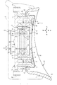
楕円リング状に形成された第2伝熱面23の長軸方向の中心位置C2を、横長楕円状に形成された第1伝熱面34の長軸方向の中心位置C1に対して、鼻梁から離れる側に偏寄させると、第1伝熱面34と、第2伝熱面23とで、眼球およびまぶたの周辺の肌面に的確に温度が異なる熱刺激を与えることができる。詳しくは、第2伝熱面23でまぶた全体を覆った状態において、まぶたおよびまぶたの周辺の肌面に、第1伝熱面34と第2伝熱面23とを確りとフィットさせて、眼球およびまぶたの周辺の肌面に温度が異なる熱刺激を的確に与えることができる。これは、まぶたの左右方向の中心位置が、眼球の左右方向の中心位置より鼻梁から離れる側に偏寄していることに対応して、第1伝熱面34の中心位置C1と、第2伝熱面23の中心位置C2を適合した対応位置に設定するからである。   The center position C2 in the major axis direction of the second heat transfer surface 23 formed in an elliptical ring shape is separated from the nose bridge with respect to the center position C1 in the major axis direction of the first heat transfer surface 34 formed in a laterally long elliptical shape. If it is biased toward the away side, the first heat transfer surface 34 and the second heat transfer surface 23 can accurately apply thermal stimuli having different temperatures to the skin surface around the eyeball and eyelid. Specifically, in a state where the entire eyelid is covered with the second heat transfer surface 23, the first heat transfer surface 34 and the second heat transfer surface 23 are securely fitted to the eyelid and the skin surface around the eyelid, and the eyeball In addition, heat stimulation with different temperatures can be given to the skin surface around the eyelids accurately. This corresponds to the fact that the center position in the left-right direction of the eyelid is offset from the center position in the left-right direction of the eyeball to the side away from the nose bridge, This is because the center position C2 of the heat transfer surface 23 is set to a compatible position.

長軸方向の中心位置が前側に向かって凹む凹曲面状に第1伝熱面34を形成すると、まぶたと第1伝熱面34との接触面積を大きくすることができ、より多くの熱刺激をまぶたを介して眼球に与えることができる。また、第1伝熱面34をまぶたにあてがった状態において、眼球に作用する圧迫力を分散させることができる。   When the first heat transfer surface 34 is formed in a concave curved surface shape whose center position in the long axis direction is recessed toward the front side, the contact area between the eyelid and the first heat transfer surface 34 can be increased, and more heat stimulation can be achieved. Can be given to the eyeball through the eyelid. Moreover, in the state which applied the 1st heat-transfer surface 34 to the eyelid, the compression force which acts on an eyeball can be disperse | distributed.

制御手段6で熱電変換素子15に供給される駆動電流の極性を所定時間ごとに反転して、第1熱供給体30および第2熱供給体20による熱刺激態様を、温熱刺激態様と冷熱刺激態様とに交互に切換えるように構成した。これによれば、第1伝熱面34と第2伝熱面23とに接触する肌面に冷熱刺激と温熱刺激を交互に与えて、美容効果を発揮することができる。   The polarity of the drive current supplied to the thermoelectric conversion element 15 by the control means 6 is reversed every predetermined time, and the thermal stimulation mode by the first heat supply body 30 and the second heat supply body 20 is changed into the thermal stimulation mode and the thermal stimulation mode. It was configured to switch alternately to the mode. According to this, it is possible to exert a beauty effect by alternately applying a cold stimulus and a warm stimulus to the skin surface contacting the first heat transfer surface 34 and the second heat transfer surface 23.

本発明の第1実施例に係る美容機器の肌処理ヘッドの横断平面図である。It is a cross-sectional top view of the skin treatment head of the beauty equipment which concerns on 1st Example of this invention. 本発明の第1実施例に係る美容機器の使用状態を示す正面図である。It is a front view which shows the use condition of the beauty equipment which concerns on 1st Example of this invention. 本発明の第1実施例に係る美容機器の全体を示す平面図である。It is a top view which shows the whole beauty equipment which concerns on 1st Example of this invention. 肌処理ヘッドの分解斜視図である。It is a disassembled perspective view of a skin treatment head. 肌処理ヘッドの要部拡大断面図である。It is a principal part expanded sectional view of a skin treatment head. 図1におけるA−A線断面図である。It is the sectional view on the AA line in FIG. 肌処理ヘッドの背面図である。It is a rear view of a skin treatment head. 美容機器の回路構成を示す模式図である。It is a schematic diagram which shows the circuit structure of beauty equipment. 本発明の第2実施例に係る美容機器の概略平面図である。It is a schematic plan view of the beauty equipment according to the second embodiment of the present invention. 本発明の第3実施例に係る肌処理ヘッドの横断平面図である。It is a cross-sectional top view of the skin treatment head which concerns on 3rd Example of this invention. 肌処理ヘッドの分解斜視図である。It is a disassembled perspective view of a skin treatment head. 本発明の第4実施例に係る肌処理ヘッドの横断平面図である。It is a cross-sectional top view of the skin treatment head which concerns on 4th Example of this invention. 肌処理ヘッドの分解斜視図である。It is a disassembled perspective view of a skin treatment head. 本発明の第5実施例に係る美容機器の肌処理ヘッドの横断平面図である。It is a cross-sectional top view of the skin treatment head of the beauty equipment which concerns on 5th Example of this invention. 本発明の第5実施例に係る美容機器の使用状態を示す正面図である。It is a front view which shows the use condition of the beauty equipment which concerns on 5th Example of this invention. アジャスト枠を装着した肌処理ヘッドの横断平面図である。It is a cross-sectional top view of the skin treatment head equipped with the adjustment frame. 本発明の第6実施例に係る美容機器の肌処理ヘッドの横断平面図である。It is a cross-sectional top view of the skin treatment head of the beauty equipment which concerns on 6th Example of this invention. 美容機器の使用状態を示す正面図である。It is a front view which shows the use condition of beauty equipment. 美容機器の全体を示す概略横断平面図である。It is a general | schematic cross-sectional top view which shows the whole beauty apparatus. 肌処理ヘッドの概略正面図である。It is a schematic front view of a skin treatment head. 本発明の第7実施例に係る美容機器の全体を示す概略横断平面図である。It is a general | schematic cross-sectional top view which shows the whole beauty equipment which concerns on 7th Example of this invention.

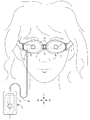
(第1実施例) 図1から図8に、本発明に係る美容機器を目元ケア用の美容機器に適用した第1実施例を示す。なお、本発明における前後、左右、上下とは、図中に示す交差矢印と、各矢印の近傍に表記した前後、左右、上下の表示に従う。図2において美容機器は、ゴーグル状に形成される本体部1と、本体部1に固定される左右一対の目元ヘッド(肌処理ヘッド)2・2と、本体部1を頭部に固定する固定バンド3と、本体部1とは別体に構成されて各目元ヘッド2に駆動電流を供給し制御するコントローラ4などで構成する。コントローラ4は、電源となる電池5と、目元ヘッド2に供給される駆動電流を生成し制御する制御基板(制御手段)6と、制御基板6の動作を切換えるスイッチ7などを備えている。 First Embodiment FIGS. 1 to 8 show a first embodiment in which a beauty device according to the present invention is applied to a beauty device for eye care. In the present invention, front / rear, left / right, and upper / lower follow the cross arrows shown in the figure and the front / rear, left / right, and upper / lower indications shown near each arrow. In FIG. 2, the beauty device includes a main body 1 formed in a goggle shape, a pair of left and right eye heads (skin treatment heads) 2 and 2 fixed to the main body 1, and fixing that fixes the main body 1 to the head. The band 3 and the main body 1 are configured separately from each other, and include a controller 4 that supplies and controls a driving current to each eye head 2. The controller 4 includes a battery 5 serving as a power source, a control board (control means) 6 that generates and controls a drive current supplied to the eye head 2, a switch 7 that switches the operation of the control board 6, and the like.

図2および図3に示すように、本体部1は、左右一対のハウジング10・10と、各ハウジング10を連結するヒンジ体11とからなり、一対のハウジング10・10には、目元ヘッド2がそれぞれ固定してある。ヒンジ体11は3個の回動軸を有する3軸ヒンジからなり、一対のハウジング10・10の相対距離および相対角度が所定の範囲内で変更可能に構成してある。これにより、ユーザーの眼球間の距離や目元部分の形状に応じて、各目元ヘッド2を目元部分の肌面に適正に接触させることができる。本体部1は、各ハウジング10の外側に連結した左右一対の固定バンド3・3で頭部に装着できるようになっており、後頭部側で一方の固定バンド3に縫着した雌側の面ファスナーに、他方の固定バンド3に縫着した雄側の面ファスナーを固定して頭部に装着することができる。   As shown in FIGS. 2 and 3, the main body 1 includes a pair of left and right housings 10, 10 and a hinge body 11 that couples the housings 10. Each is fixed. The hinge body 11 is composed of a three-axis hinge having three rotation axes, and is configured such that the relative distance and relative angle of the pair of housings 10 and 10 can be changed within a predetermined range. Thereby, each eye head 2 can be appropriately brought into contact with the skin surface of the eye part according to the distance between the user's eyeballs and the shape of the eye part. The main body 1 can be attached to the head with a pair of left and right fixing bands 3, 3 connected to the outside of each housing 10, and a female surface fastener that is sewn to one fixing band 3 on the rear head side. In addition, the male hook-and-loop fastener sewn on the other fixing band 3 can be fixed and attached to the head.

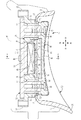
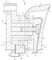
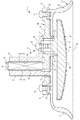
図1に示すように、目元ヘッド2には、温熱生成手段13および冷熱生成手段14と、温熱生成手段13または冷熱生成手段14で生成された熱を肌面に伝導するアイプレート(第1熱供給体)30と、冷熱生成手段14または温熱生成手段13で生成された熱を肌面に伝導するアイカップ(第2熱供給体)20とが設けてある。図1、図4および図6に示すように、アイカップ20は、肌面との接触部分の側へ向かって開口するカップ状に形成して、アイプレート30の周囲を囲む状態で配置してある。温熱生成手段13および冷熱生成手段14は1個の熱電変換素子15で構成してあり、その温熱を生成する温熱面16と、冷熱を生成する冷熱面17とが、それぞれ温熱生成手段13および冷熱生成手段14として機能する。熱電変換素子15は、各面16・17が前後に指向する状態で配置してあり、制御基板6で熱電変換素子15に順方向の駆動電流を供給したとき、前面側が温熱面16に、後面側が冷熱面17になるように配置してある。このように、温熱生成手段13および冷熱生成手段14を1個の熱電変換素子15で構成すると、温熱生成手段13と冷熱生成手段14を個別に設ける場合に比べて、熱生成構造を簡素化して肌処理ヘッド2の製造に要するコストを削減できる。また、熱電変換素子15で生成される温熱と冷熱の双方を利用して肌面に熱刺激を付与するので、熱電変換素子15で生成した温熱と冷熱を無駄なく有効に活用できる。   As shown in FIG. 1, the eye head 2 includes a heat generation means 13 and a cold heat generation means 14, and an eye plate (first heat) that conducts heat generated by the heat generation means 13 or the cold heat generation means 14 to the skin surface. (Supply body) 30 and an eye cup (second heat supply body) 20 that conducts the heat generated by the cold heat generating means 14 or the warm heat generating means 13 to the skin surface are provided. As shown in FIGS. 1, 4, and 6, the eye cup 20 is formed in a cup shape that opens toward the side of the contact portion with the skin surface, and is arranged so as to surround the periphery of the eye plate 30. is there. The warm heat generating means 13 and the cold heat generating means 14 are composed of a single thermoelectric conversion element 15, and a hot surface 16 that generates the heat and a cold surface 17 that generates the cold are respectively the hot heat generating means 13 and the cold heat. It functions as the generation means 14. The thermoelectric conversion element 15 is arranged in a state in which the surfaces 16 and 17 are directed forward and backward, and when a forward drive current is supplied to the thermoelectric conversion element 15 by the control board 6, the front side is the thermal surface 16, and the rear surface It arrange | positions so that the side may become the cold surface 17. FIG. Thus, when the heat generation means 13 and the cold heat generation means 14 are configured by one thermoelectric conversion element 15, the heat generation structure is simplified as compared with the case where the heat generation means 13 and the cold heat generation means 14 are provided separately. The cost required for manufacturing the skin treatment head 2 can be reduced. In addition, since heat stimulation is applied to the skin surface using both the heat and cold generated by the thermoelectric conversion element 15, the heat and cold generated by the thermoelectric conversion element 15 can be used effectively without waste.

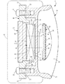
図1および図4に示すように、アイカップ20は、楕円板状のベース壁21と、ベース壁21に連続して形成される湾曲壁22とで全体がカップ状に形成してある。湾曲壁22は、カップ開口縁へ向かって徐々に拡開するラッパ状に形成してあり、湾曲壁22のカップ開口縁に第2伝熱面23が設けてある。図7に示すように、アイカップ20は、背面視において横長の楕円状に形成してあり、その第2伝熱面23は楕円リング状に形成してある。また、第2伝熱面23は、平面視においてまぶたの周辺の肌面形状に対応して、左右中央部が前側に向かって凹む凹曲面状に形成してあり、第2伝熱面23の全体が、まぶたの周辺の肌面に接触するようになっている。   As shown in FIGS. 1 and 4, the eye cup 20 is entirely formed in a cup shape with an elliptical plate-like base wall 21 and a curved wall 22 formed continuously with the base wall 21. The curved wall 22 is formed in a trumpet shape that gradually expands toward the cup opening edge, and a second heat transfer surface 23 is provided on the cup opening edge of the curved wall 22. As shown in FIG. 7, the eyecup 20 is formed in a horizontally long elliptical shape in the rear view, and the second heat transfer surface 23 is formed in an elliptical ring shape. Further, the second heat transfer surface 23 is formed in a concave curved surface shape in which the left and right central portions are recessed toward the front side in correspondence with the skin surface shape around the eyelid in plan view. The whole is in contact with the skin surface around the eyelids.

上記のように、アイカップ20の湾曲壁22をカップ開口縁へ向かって徐々に拡開するラッパ状に形成すると、第2熱供給体20の湾曲壁22の内面をまぶた周辺の肌面に沿わせて、湾曲壁22と肌面との接触面積を大きくすることができ、接触圧を分散させて接触による肌面への刺激を軽減でき、快適に美容機器を使用することができる。   As described above, when the curved wall 22 of the eye cup 20 is formed in a trumpet shape that gradually expands toward the cup opening edge, the inner surface of the curved wall 22 of the second heat supply body 20 is aligned with the skin surface around the eyelid. Accordingly, the contact area between the curved wall 22 and the skin surface can be increased, the contact pressure can be dispersed to reduce irritation to the skin surface by contact, and the beauty device can be used comfortably.

図5および図6に示すように、アイカップ20のベース壁21の前面中央部には、熱電変換素子15の冷熱面17と接触して熱を受取る第2伝熱体24が一体に突出形成してある。第2伝熱体24の中央には、熱電変換素子15の外形形状と一致する凹部25が形成してあり、凹部25の底面は、冷熱面17と接触して冷熱を受取る受熱面26となっている。このように、アイカップ20は第2伝熱体24を介して熱電変換素子15の冷熱面17と接続されているので、冷熱面17から伝導された冷熱で、アイカップ20の全体を冷却できる。また、第2伝熱面23をまぶたの周辺の肌面に接触させることにより、接触する肌面に冷熱刺激を与えることができる。冷熱面17と受熱面26とは、シリコーンゴム製の伝熱シートを介して密着させて、熱の伝導効率を向上させている。   As shown in FIGS. 5 and 6, a second heat transfer body 24 that contacts the cold surface 17 of the thermoelectric conversion element 15 and receives heat is integrally formed at the center of the front surface of the base wall 21 of the eye cup 20. It is. A recess 25 that matches the outer shape of the thermoelectric conversion element 15 is formed at the center of the second heat transfer body 24, and the bottom surface of the recess 25 is a heat receiving surface 26 that contacts the cooling surface 17 and receives cooling. ing. Thus, since the eyecup 20 is connected to the cooling surface 17 of the thermoelectric conversion element 15 via the second heat transfer body 24, the entire eyecup 20 can be cooled by the cooling heat conducted from the cooling surface 17. . Further, by bringing the second heat transfer surface 23 into contact with the skin surface around the eyelid, it is possible to give a cold stimulus to the contacting skin surface. The cold surface 17 and the heat receiving surface 26 are brought into close contact with each other through a heat transfer sheet made of silicone rubber to improve heat conduction efficiency.

図1および図6に示すように、ベース壁21の第2伝熱体24の左右には、円形の連通開口27・27がそれぞれ開設してあり、第2伝熱体24の上下には、ねじボス28・28がそれぞれ前方に向かって突設してある。連通開口27は、後述する断熱筒壁47を係合するために形成してあり、ねじボス28は、後述する断熱ホルダー46を締結するために設けてある。   As shown in FIG. 1 and FIG. 6, circular communication openings 27 and 27 are respectively opened on the left and right sides of the second heat transfer body 24 of the base wall 21, and above and below the second heat transfer body 24, Screw bosses 28 and 28 are projected forward. The communication opening 27 is formed to engage a heat insulating cylindrical wall 47 described later, and the screw boss 28 is provided for fastening a heat insulating holder 46 described later.

図1および図4に示すようにアイプレート30は、背面視においてまぶたの外郭形状に対応して横長楕円状に形成した伝熱ベース31と、伝熱ベース31の前面左右にそれぞれ突設される締結ボス32・32とを一体に形成してある。各締結ボス32部には、段付穴状の締結穴が前後に貫通する状態で形成してあり、この締結穴に締結ビス(第1締結体)43が挿通される。伝熱ベース31の後面は、楕円状の第1伝熱面34として形成してあり、第1伝熱面34は、眼球の膨らみ形状に対応して凹曲面状に形成してある。これにより、まぶたと第1伝熱面34との接触面積を大きくすることができ、より多くの熱刺激をまぶたを介して眼球に与えることができる。また、第1伝熱面34をまぶたにあてがった状態において、眼球に作用する圧迫力を分散させることができる。図1において、符号35は、第1伝熱面34と接触するまぶたの刺激を緩和するシリコーンゴム製のカバーである。   As shown in FIGS. 1 and 4, the eye plate 30 protrudes from the heat transfer base 31 formed in a horizontally long oval shape corresponding to the outer shape of the eyelid in rear view, and to the left and right of the front surface of the heat transfer base 31. The fastening bosses 32 and 32 are integrally formed. Each fastening boss 32 is formed with a stepped hole-like fastening hole extending in the front-rear direction, and a fastening screw (first fastening body) 43 is inserted into the fastening hole. The rear surface of the heat transfer base 31 is formed as an elliptical first heat transfer surface 34, and the first heat transfer surface 34 is formed in a concave curved surface shape corresponding to the bulge shape of the eyeball. Thereby, the contact area of an eyelid and the 1st heat-transfer surface 34 can be enlarged, and more thermal stimulation can be given to an eyeball via an eyelid. Moreover, in the state which applied the 1st heat-transfer surface 34 to the eyelid, the compression force which acts on an eyeball can be disperse | distributed. In FIG. 1, reference numeral 35 denotes a cover made of silicone rubber that relieves the irritation of the eyelid contacting the first heat transfer surface 34.

図1および図4に示すように、第1伝熱体37は、連結軸(伝熱軸部)38と、熱電変換素子15の温熱面16に接触する受熱プレート(第1受熱部)39とを一体に備えている。受熱プレート39の四隅は丸めてあり、その後面中央には受熱座41が突設してある。また、前面左右には左右一対の連結軸38が突設してある。受熱座41は、熱電変換素子15の外形形状より僅かに大きな四角形状に形成してあり、受熱座41の後面は、温熱面16と接触して温熱を受取る受熱面42となっている。温熱面16と受熱面42とは、シリコーンゴム製の伝熱シートを介して密着させて、熱の伝導効率を向上させている。   As shown in FIGS. 1 and 4, the first heat transfer body 37 includes a connecting shaft (heat transfer shaft portion) 38, and a heat receiving plate (first heat receiving portion) 39 that contacts the hot surface 16 of the thermoelectric conversion element 15. Is integrated. The four corners of the heat receiving plate 39 are rounded, and a heat receiving seat 41 projects from the center of the rear surface. A pair of left and right connecting shafts 38 project from the left and right sides of the front surface. The heat receiving seat 41 is formed in a rectangular shape that is slightly larger than the outer shape of the thermoelectric conversion element 15, and the rear surface of the heat receiving seat 41 is a heat receiving surface 42 that contacts the warm surface 16 and receives the heat. The hot surface 16 and the heat receiving surface 42 are in close contact with each other through a heat transfer sheet made of silicone rubber to improve heat conduction efficiency.

図5に示すように、各連結軸38にはねじ穴が形成してあり、連結軸38の後端をアイプレート30の締結ボス32に挿入した状態で、締結ビス43を締結穴の側からねじ穴にねじ込むことにより、アイプレート30と第1伝熱体37とを一体化できる。このように、アイプレート30は第1伝熱体37を介して熱電変換素子15の温熱面16と接続されているので、温熱面16から伝導された温熱で、アイプレート30および第1伝熱体37の全体を加熱できる。また、第1伝熱面34をまぶたの肌面に接触させることにより、まぶたを介して眼球に温熱刺激を与えることができる。   As shown in FIG. 5, each connecting shaft 38 is formed with a screw hole, and the fastening screw 43 is inserted from the fastening hole side with the rear end of the connecting shaft 38 inserted into the fastening boss 32 of the eye plate 30. By screwing into the screw holes, the eye plate 30 and the first heat transfer body 37 can be integrated. Thus, since the eye plate 30 is connected to the hot surface 16 of the thermoelectric conversion element 15 via the first heat transfer body 37, the eye plate 30 and the first heat transfer are heated by the heat conducted from the hot surface 16. The entire body 37 can be heated. In addition, by bringing the first heat transfer surface 34 into contact with the skin surface of the eyelid, it is possible to give a thermal stimulus to the eyeball through the eyelid.

アイカップ20、アイプレート30、および第1伝熱体37は、アルミニウム、真鍮、銅などの熱伝導率の高い金属材料を素材として形成することができる。本実施例では、アルミニウムを素材としたダイキャスト成形品に切削加工を施して、先の各部材20・30・37を形成した。熱伝導率の高いアルミニウムを素材としてアイカップ20、アイプレート30、および第1伝熱体37を形成するので、それぞれの全体に素早く熱を伝導して、より短い時間で所定の温度に冷却および加熱することができる。   The eye cup 20, the eye plate 30, and the first heat transfer body 37 can be formed using a metal material having high thermal conductivity such as aluminum, brass, or copper as a raw material. In this embodiment, the die-cast molded product made of aluminum was cut to form the respective members 20, 30, and 37. Since the eye cup 20, the eye plate 30, and the first heat transfer body 37 are formed using aluminum having a high thermal conductivity, the heat is quickly conducted to the whole, and cooled to a predetermined temperature in a shorter time. Can be heated.

図1、図4および図6に示すように、第1伝熱体37と第2伝熱体24との間に、両伝熱体24・37間の熱移動を阻止する断熱ホルダー(スペーサー)46が配置してある。断熱ホルダー46は、左右一対の断熱筒壁47と、両筒壁47の間に形成される四角枠状の断熱枠48と、断熱枠48の上下枠部に形成される一対の締結座51・51とを一体に備えた、断熱性に優れたフッ素樹脂を素材とする射出成形品からなる。一対の断熱筒壁47は断熱枠48の左右枠部と一体に形成されており、各断熱筒壁47には、アイカップ20のベース壁21を受止める半円弧状の受止座52が形成してある。断熱筒壁47の内径寸法は、連結軸38の外径寸法よりも大きく設定してある。上記のように、断熱ホルダー46と断熱筒壁47とを一体に形成すると、断熱筒壁47を独立した部品として形成する場合に比べて、断熱構造の構成部品点数を少なくできるので、目元ヘッド2の構造を簡素化し、目元ヘッド2の製造に要するコストを削減できる。各断熱筒壁47には、ハウジング10に固定するための筒軸状の固定部53がそれぞれ設けてある。   As shown in FIGS. 1, 4, and 6, a heat insulating holder (spacer) is provided between the first heat transfer body 37 and the second heat transfer body 24 to prevent heat transfer between the heat transfer bodies 24 and 37. 46 is arranged. The heat insulating holder 46 includes a pair of left and right heat insulating cylindrical walls 47, a square frame-shaped heat insulating frame 48 formed between the two cylindrical walls 47, and a pair of fastening seats 51 formed on the upper and lower frame portions of the heat insulating frame 48. It is made of an injection molded product made of a fluororesin excellent in heat insulation, which is integrally provided with 51. The pair of heat insulating cylinder walls 47 are formed integrally with the left and right frame portions of the heat insulating frame 48, and a semicircular arc receiving seat 52 for receiving the base wall 21 of the eye cup 20 is formed on each heat insulating cylinder wall 47. It is. The inner diameter dimension of the heat insulating cylinder wall 47 is set larger than the outer diameter dimension of the connecting shaft 38. As described above, when the heat insulating holder 46 and the heat insulating cylindrical wall 47 are integrally formed, the number of components of the heat insulating structure can be reduced as compared with the case where the heat insulating cylindrical wall 47 is formed as an independent component. The cost of manufacturing the eye head 2 can be reduced. Each heat insulating cylinder wall 47 is provided with a cylindrical shaft-like fixing portion 53 for fixing to the housing 10.

断熱ホルダー46は、上下の締結座51・51をそれぞれ締結ビス(第2締結体)44でベース壁21に形成したねじボス28・28に締結固定することにより、アイカップ20と一体に固定してある。図6に示すように、断熱ホルダー46の上下の締結座51に、ベース壁21のねじボス28をあてがった状態で、締結ビス44をねじボス28のねじ穴にねじ込むことにより、アイカップ20が断熱ホルダー46と一体化される。この締結状態では、各断熱筒壁47が各連通開口27と係合しており、また、両受止座52・52が、連通開口27の周囲のベース壁21を受止めるので、アイカップ20と断熱ホルダー46とを強固に固定できる。   The heat insulating holder 46 is fixed integrally with the eye cup 20 by fastening the upper and lower fastening seats 51 and 51 to screw bosses 28 and 28 formed on the base wall 21 with fastening screws (second fastening bodies) 44, respectively. It is. As shown in FIG. 6, with the screw boss 28 of the base wall 21 applied to the upper and lower fastening seats 51 of the heat insulating holder 46, the eye cup 20 is screwed into the screw hole of the screw boss 28 by screwing the fastening screw 44. It is integrated with the heat insulating holder 46. In this fastened state, each heat insulating cylindrical wall 47 is engaged with each communication opening 27, and both receiving seats 52 and 52 receive the base wall 21 around the communication opening 27. And the heat insulating holder 46 can be firmly fixed.

第1伝熱体37は、その受熱プレート39が断熱ホルダー46に位置決めされた状態で接合してある。詳しくは、受熱座41は、断熱枠48に嵌め込まれて、その内周面で位置決めされている。また、受熱プレート39と断熱枠48とが密着して、第1伝熱体37と断熱ホルダー46とが位置決めされており、この状態の連結軸38は断熱筒壁47を前後に貫通している。上記の位置決め状態において、締結ビス43を締結穴を介して連結軸38のねじ穴にねじ込むことにより、アイプレート30および第1伝熱体37と断熱ホルダー46とを強固に固定できる。この状態における断熱筒壁47は、伝熱ベース31と受熱プレート39とで、強固に挟持固定される。このとき、熱電変換素子15は、その温熱面16が第1伝熱体37の受熱面42と密着し、冷熱面17がアイカップ20の受熱面26と密着する状態で、アイカップ20と第1伝熱体37とで挟持固定されている。また、連結軸38の外周面と断熱筒壁47の内周面との間には、互いの面が全周囲において接触しない状態の断熱空間Sが形成されている。   The first heat transfer body 37 is joined in a state where the heat receiving plate 39 is positioned on the heat insulating holder 46. Specifically, the heat receiving seat 41 is fitted into the heat insulating frame 48 and positioned on the inner peripheral surface thereof. Further, the heat receiving plate 39 and the heat insulating frame 48 are in close contact with each other, and the first heat transfer body 37 and the heat insulating holder 46 are positioned, and the connecting shaft 38 in this state penetrates the heat insulating cylindrical wall 47 forward and backward. . In the above positioning state, the eye plate 30, the first heat transfer body 37, and the heat insulating holder 46 can be firmly fixed by screwing the fastening screw 43 into the screw hole of the connecting shaft 38 through the fastening hole. The heat insulating cylindrical wall 47 in this state is firmly clamped and fixed by the heat transfer base 31 and the heat receiving plate 39. At this time, the thermoelectric conversion element 15 has the hot surface 16 in close contact with the heat receiving surface 42 of the first heat transfer body 37, and the cold surface 17 is in close contact with the heat receiving surface 26 of the eye cup 20. The heat transfer body 37 is sandwiched and fixed. Further, a heat insulating space S is formed between the outer peripheral surface of the connecting shaft 38 and the inner peripheral surface of the heat insulating cylinder wall 47 in a state where the surfaces do not contact each other around the entire periphery.

上記のように、アイカップ20と、断熱ホルダー46と、アイプレート30および第1伝熱体37とは、締結ビス43・44で強固に固定された状態で一体化してある。この組立状態において、まぶたに接触する第1伝熱面34は、まぶたの周辺の肌面に接触する第2伝熱面23よりも、カップ内奥側、すなわちベース壁21に近接する側へ凹んだ位置に配置してある。このように、第1伝熱面34を第2伝熱面23よりも凹んだ位置に配置するのは、眼を閉じた状態におけるまぶたが、まぶたの周辺の肌面よりも前側に位置することに対応したものである。これにより、両伝熱面34・23をまぶたとまぶたの周辺の肌面に確りとフィットさせることができる。また、アイプレート30の周囲を囲む状態でカップ状のアイカップ20を配置していると、アイプレート30とアイカップ20を3次元空間を介して隣接させながら、両者20・30が互いに熱干渉しあうことを防止できる。   As described above, the eye cup 20, the heat insulating holder 46, the eye plate 30, and the first heat transfer body 37 are integrated in a state of being firmly fixed by the fastening screws 43 and 44. In this assembled state, the first heat transfer surface 34 that comes into contact with the eyelid is recessed to the inner side of the cup, that is, the side closer to the base wall 21 than the second heat transfer surface 23 that comes into contact with the skin surface around the eyelid. It is arranged in the position. As described above, the first heat transfer surface 34 is disposed at a position recessed from the second heat transfer surface 23 because the eyelid in a state where the eyes are closed is positioned in front of the skin surface around the eyelid. It corresponds to. Thereby, both the heat-transfer surfaces 34 and 23 can be reliably fitted on the skin surface around the eyelid and the eyelid. Further, when the cup-shaped eye cup 20 is disposed so as to surround the periphery of the eye plate 30, the eye plates 30 and the eye cup 20 are adjacent to each other via a three-dimensional space, and both 20 and 30 are in thermal interference with each other. You can prevent them from meeting.

図7に示すように、楕円リング状に形成された第2伝熱面23の長軸方向の中心位置C2を、横長楕円状に形成された第1伝熱面34の長軸方向の中心位置C1に対して、鼻梁から離れる側に偏寄させて配置してある。これは、まぶたの左右方向の中心位置が、眼球の左右方向の中心位置より鼻梁から離れる側に偏寄しているので、そのため、先のように中心位置C1・C2をずらしておくことにより、第2伝熱面23でまぶた全体を覆った状態において、第1伝熱面34を眼球およびまぶたに確りとフィットさせることができる。さらに、第2伝熱面23を、まぶたとまぶたの周辺の肌面に確りとフィットさせることができ、全体として眼球およびまぶたの周辺の肌面に的確に冷温の熱刺激を与えることができる。   As shown in FIG. 7, the center position C2 in the major axis direction of the second heat transfer surface 23 formed in an elliptical ring shape is the center position in the major axis direction of the first heat transfer surface 34 formed in a horizontally long ellipse shape. It is arranged so as to be offset from C1 on the side away from the nose bridge. This is because the center position in the left-right direction of the eyelid is offset from the center position in the left-right direction of the eyeball to the side away from the nasal bridge, so by shifting the center positions C1 and C2 as before, In a state where the entire eyelid is covered with the second heat transfer surface 23, the first heat transfer surface 34 can be surely fitted to the eyeball and the eyelid. Further, the second heat transfer surface 23 can be surely fitted to the skin surface around the eyelids and the eyelids, and as a whole, the heat stimulus of the cold temperature can be accurately given to the eyeball and the skin surface around the eyelids as a whole.

第1伝熱体37と第2伝熱体24との間に断熱ホルダー46を配置すると、両伝熱体37・24の間の熱移動を断熱ホルダー46の断熱作用で阻止できる。従って、温熱生成手段13で生成した温熱、および冷熱生成手段14で生成した冷熱を、それぞれ第1伝熱体37と第2伝熱体24を介して、アイプレート30またはアイカップ20に効果的に伝導して、熱伝導経路における熱の無駄な消費を防止できる。また、断熱筒壁47に加えて、断熱空間S部分の空気で、アイカップ20のベース壁21と第1伝熱体37との間の熱移動をさらに効果的に阻止できる。従って、第1伝熱体37からアイプレート30への熱移動、および第2伝熱体24からアイカップ20への熱移動を、さらに効果的に行って、熱伝導経路における熱の無駄な消費をさらに確実に防止できる。   If the heat insulating holder 46 is disposed between the first heat transfer body 37 and the second heat transfer body 24, heat transfer between the heat transfer bodies 37 and 24 can be prevented by the heat insulating action of the heat insulating holder 46. Therefore, the heat generated by the heat generating means 13 and the heat generated by the cold heat generating means 14 are effectively applied to the eye plate 30 or the eye cup 20 via the first heat transfer body 37 and the second heat transfer body 24, respectively. It is possible to prevent wasteful consumption of heat in the heat conduction path. Further, in addition to the heat insulating cylindrical wall 47, heat transfer between the base wall 21 of the eye cup 20 and the first heat transfer body 37 can be more effectively prevented by the air in the heat insulating space S portion. Therefore, the heat transfer from the first heat transfer body 37 to the eye plate 30 and the heat transfer from the second heat transfer body 24 to the eye cup 20 are further effectively performed, and wasteful consumption of heat in the heat conduction path is performed. Can be prevented more reliably.

ここで、目元ヘッド2の組立て手順を説明する。まず、アイカップ20の凹部25に、熱電変換素子15の冷熱面17が伝熱シートを介して受熱面26と密着するように配置する。断熱ホルダー46をアイカップ20の前面側から断熱筒壁47を連通開口27に挿通し、2個の締結ビス44を締結座51を介してねじボス28にねじ込み、アイカップ20と断熱ホルダー46を一体に固定する。このとき熱電変換素子15の接続リード56は、第2伝熱体24と断熱枠48との隙間に通してある(図6参照)。次に、固定したアイカップ20と断熱ホルダー46との前側から連結軸38を断熱筒壁47に挿通しながら、断熱枠48に受熱座41を嵌め込んで、第1伝熱体37を断熱ホルダー46に位置決めした状態で組付ける。さらに、アイプレート30を2個の締結ビス43を締結穴を介して連結軸38のねじ穴にねじ込んで、断熱ホルダー46と、アイプレート30および第1伝熱体37とを一体に固定して、目元ヘッド2を1個のユニット部品として一体化する。   Here, an assembly procedure of the eye head 2 will be described. First, it arrange | positions so that the cold surface 17 of the thermoelectric conversion element 15 may contact | adhere to the heat receiving surface 26 through a heat-transfer sheet | seat in the recessed part 25 of the eyecup 20. FIG. The heat insulating holder 46 is inserted from the front side of the eye cup 20 through the heat insulating cylindrical wall 47 into the communication opening 27, and two fastening screws 44 are screwed into the screw bosses 28 via the fastening seats 51, so that the eye cup 20 and the heat insulating holder 46 are connected. Fix together. At this time, the connection lead 56 of the thermoelectric conversion element 15 is passed through the gap between the second heat transfer body 24 and the heat insulating frame 48 (see FIG. 6). Next, the heat receiving seat 41 is fitted into the heat insulating frame 48 while the connecting shaft 38 is inserted into the heat insulating cylindrical wall 47 from the front side of the fixed eye cup 20 and the heat insulating holder 46, so that the first heat transfer body 37 is attached to the heat insulating holder. Assembled in the state positioned at 46. Further, the eye plate 30 is screwed into two screw holes of the connecting shaft 38 through the fastening holes, and the heat insulating holder 46, the eye plate 30 and the first heat transfer body 37 are fixed integrally. The eye head 2 is integrated as one unit part.

図3に示すように、1個のユニット部品とされた目元ヘッド2は、固定ビス55でハウジング10に固定してある。ハウジング10は、前ハウジング10aと、左右に分割できる後ハウジング10bとで構成してある。目元ヘッド2は、固定部53を間にして前後から前ハウジング10aおよび後ハウジング10bを装着し、前側から固定ビス55をねじ込むことによりハウジング10に固定される。左右の熱電変換素子15の接続リード56は、右側のハウジング10に設けた入力端子57(図2参照)に接続してあり、入力端子57に給電リード58の先端のプラグ59を差し込むことで、コントローラ4から熱電変換素子15に駆動電流を供給することができる。熱電変換素子15は、制御基板6から供給される駆動電流により温熱と冷熱を生成する。左右のハウジング10・10は、基本的には同一部材であり、入力端子57の有無で構造の差異がある。また、左右の目元ヘッド2・2も同一部材である。   As shown in FIG. 3, the eye head 2, which is a single unit component, is fixed to the housing 10 with a fixing screw 55. The housing 10 includes a front housing 10a and a rear housing 10b that can be divided into left and right. The eye head 2 is fixed to the housing 10 by attaching the front housing 10a and the rear housing 10b from the front and rear with the fixing portion 53 interposed therebetween and screwing the fixing screw 55 from the front side. The connection leads 56 of the left and right thermoelectric conversion elements 15 are connected to an input terminal 57 (see FIG. 2) provided on the right housing 10, and by inserting a plug 59 at the tip of the power supply lead 58 into the input terminal 57, A drive current can be supplied from the controller 4 to the thermoelectric conversion element 15. The thermoelectric conversion element 15 generates heat and cold by the drive current supplied from the control board 6. The left and right housings 10 and 10 are basically the same member, and there is a difference in structure depending on the presence or absence of the input terminal 57. The left and right eye heads 2 and 2 are also the same member.

次に、目元ケア用の美容機器の使用方法を説明する。まず、本体部1を固定バンド3で目元に装着する。詳しくは、左右のアイプレート30およびアイカップ20のそれぞれを、まぶたとまぶたの周辺の肌面に接触するように本体部1を目元にあてがい、左右の固定バンド3・3を後頭部側で重ねて、面ファスナーで固定する。このとき、左右のハウジング10・10は、ヒンジ体11で連結されているので、装着するユーザーの顔形状に合致するようにハウジング10・10の相対距離と相対角度を調整することができる。   Next, a method of using a beauty device for eye care will be described. First, the main body 1 is attached to the eyes with the fixing band 3. Specifically, the left and right eye plates 30 and eye cups 20 are respectively placed on the eyes so as to contact the eyelids and the skin surface around the eyelids, and the left and right fixing bands 3 and 3 are overlapped on the back of the head. Fasten with a hook-and-loop fastener. At this time, since the left and right housings 10 and 10 are connected by the hinge body 11, the relative distance and relative angle of the housings 10 and 10 can be adjusted so as to match the face shape of the wearing user.

コントローラ4のスイッチ7を押下すると、制御基板6が熱電変換素子15に順方向の駆動電流を供給し、その温熱面16および冷熱面17で温熱と冷熱が生成される。温熱面16で生成された温熱は、第1伝熱体37を介してアイプレート30に伝導され、その第1伝熱面34でまぶたを介して眼球に温熱刺激を与える。また、冷熱面17で生成された冷熱は、第2伝熱体24を介してアイカップ20に伝導され、その第2伝熱面23でまぶたの周辺の肌面に冷熱刺激を与える。これにより、眼球およびまぶたの周辺の肌面に異なる温度の熱刺激を与えて、美容効果を発揮することができる。制御基板6が供給する駆動電流は、予め設定された時間が経過し、あるいは再度スイッチ7を押下することで停止し、これにより熱刺激の付与が終了する。   When the switch 7 of the controller 4 is pressed, the control board 6 supplies a forward drive current to the thermoelectric conversion element 15, and hot and cold heat is generated on the hot and cold surfaces 16 and 17. The warm heat generated on the warm surface 16 is conducted to the eye plate 30 via the first heat transfer body 37, and the first heat transfer surface 34 gives a warm stimulus to the eyeball via the eyelid. Further, the cold heat generated on the cold surface 17 is conducted to the eye cup 20 through the second heat transfer body 24, and the second heat transfer surface 23 gives a cold stimulus to the skin surface around the eyelid. Thereby, the thermal stimulation of different temperature can be given to the skin of the eyeball and the periphery of an eyelid, and the beauty effect can be exhibited. The drive current supplied by the control board 6 stops when a preset time elapses or when the switch 7 is pressed again, whereby the application of thermal stimulation is completed.

本実施形態では、第1伝熱面34での温熱刺激の温度は、35℃から45℃に設定してある。温度が35℃より低いと、体表面とほぼ同温度であるため、加熱による肌面の温熱刺激効果が得られないからである。また、温度が45℃より高いと、肌面に低温やけどを生じるおそれがあるためである。第2伝熱面23での冷熱刺激の温度は、15℃から20℃に設定してある。温度が15℃より低いと、過度の冷却により肌面に痛みを生じるおそれがあるからである。また、温度が20℃より高いと、冷却による肌面の冷熱刺激効果が得られ難いからである。   In the present embodiment, the temperature of the thermal stimulation on the first heat transfer surface 34 is set to 35 ° C. to 45 ° C. This is because if the temperature is lower than 35 ° C., the temperature is almost the same as that of the body surface, so that the skin surface thermal stimulation effect by heating cannot be obtained. Moreover, it is because there exists a possibility of producing a low-temperature burn on the skin surface when temperature is higher than 45 degreeC. The temperature of the cold stimulus on the second heat transfer surface 23 is set to 15 ° C. to 20 ° C. This is because if the temperature is lower than 15 ° C., excessive cooling may cause pain on the skin surface. Further, when the temperature is higher than 20 ° C., it is difficult to obtain the effect of cooling the skin surface by cooling.

熱電変換素子15は、制御基板6で逆方向の駆動電流を供給することで、順方向の駆動電流が供給された場合とは逆の発熱状態にすることができる。詳しくは、熱電変換素子15に逆方向の駆動電流を供給すると、熱電変換素子15の前面側を冷熱を生成する冷熱面17として機能させ、後面側を温熱を生成する温熱面16として機能させることができる。これにより、第1伝熱面34で冷熱刺激を与え、第2伝熱面23で温熱刺激を与えることができる。また、制御基板6で駆動電流の極性を所定時間ごとに反転して交互に供給することで、アイプレート30およびアイカップ20による熱刺激態様を、温熱刺激態様と冷熱刺激態様とに交互に切換えるようにすることができる。これによれば、目元ヘッド2を目元部分に装着した状態のままで、眼球およびまぶたの周辺の肌面に冷熱刺激と温熱刺激を交互に与えて、美容効果を発揮することができる。   The thermoelectric conversion element 15 can be in a heat generation state opposite to the case where the forward drive current is supplied by supplying the reverse drive current with the control board 6. Specifically, when a reverse drive current is supplied to the thermoelectric conversion element 15, the front side of the thermoelectric conversion element 15 functions as the cooling surface 17 that generates cold, and the rear side functions as the heating surface 16 that generates heat. Can do. As a result, the first heat transfer surface 34 can give a cold stimulus, and the second heat transfer surface 23 can give a warm stimulus. Further, the polarity of the drive current is inverted every predetermined time on the control board 6 and supplied alternately so that the thermal stimulation mode by the eye plate 30 and the eye cup 20 is alternately switched between the thermal stimulation mode and the cold stimulation mode. Can be. According to this, it is possible to exert a beauty effect by alternately applying the cold stimulus and the warm stimulus to the skin surface around the eyeball and the eyelid while the eye head 2 is attached to the eye portion.

制御基板6による駆動電流の供給形態は、スイッチ7を押下するごとに順方向供給、逆方向供給、反転供給の3種の形態を順次切換え可能とすることができる。この場合には、ユーザーの好みに応じた熱刺激付与態様を選択して、眼球およびまぶたの周辺の肌面に熱刺激を与えることができる。   The drive current supply mode by the control board 6 can be switched sequentially among three types of forward supply, reverse supply, and reverse supply each time the switch 7 is pressed. In this case, it is possible to apply a thermal stimulus to the skin around the eyeball and eyelid by selecting a thermal stimulus application mode according to the user's preference.

上記のように、熱刺激を付与するアイプレート30と、まぶたの周辺の肌面に熱刺激を付与するアイカップ20とを肌処理ヘッド2に設けて、目元用の美容機器を構成した。この美容機器によれば、眼球およびまぶたの周辺の肌面に異なる温度の熱刺激を与えて、美容効果を発揮することができる。   As described above, the eye plate 30 for applying thermal stimulation and the eye cup 20 for applying thermal stimulation to the skin surface around the eyelids are provided in the skin treatment head 2 to constitute a beauty device for the eyes. According to this beauty device, it is possible to exert a beauty effect by applying thermal stimulation at different temperatures to the skin surface around the eyeball and eyelid.

目元ヘッド2のアイプレート30およびアイカップ20を、まぶたとまぶたの周辺の肌面に接触させると、カップ形状のアイカップ20と肌面とにより密閉空間が形成される。アイカップ20の温度が周囲温度よりも充分に低い場合には、この密閉空間内の空気が冷却されて、アイカップ20の内面に結露による水滴が生じる。しかし、密閉空間内の空気は、アイプレート30により加熱されるので、アイカップ20で過度に冷却されることがない。これにより、密閉空間に面したアイカップ20の内面に結露による水滴が生じるのを防ぐことができ、肌面が濡れることがなく、快適に美容機器を使用することができる。   When the eye plate 30 and the eye cup 20 of the eye head 2 are brought into contact with the eyelid and the skin surface around the eyelid, a sealed space is formed by the cup-shaped eye cup 20 and the skin surface. When the temperature of the eye cup 20 is sufficiently lower than the ambient temperature, the air in the sealed space is cooled, and water droplets due to condensation are generated on the inner surface of the eye cup 20. However, since the air in the sealed space is heated by the eye plate 30, it is not excessively cooled by the eye cup 20. Thereby, it can prevent that the water droplet by condensation forms on the inner surface of the eyecup 20 facing the sealed space, the skin surface does not get wet, and the beauty device can be used comfortably.

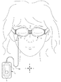
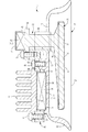
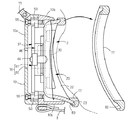
(第2実施例) 図9に、本発明に係る美容機器の第2実施例を示す。本実施例では、美容機器を手持ち式の美容機器として構成した点と、肌処理ヘッド2に設けた第1熱供給体30の第1伝熱面37の形状、および第2熱供給体20の第2伝熱面23の形状を変更する点とが第1実施例と異なっている。他は第1実施例と同じであるので、同じ部材に同じ符号を付してその説明を省略する。図9において、本実施例の美容機器は、グリップを兼ねる左右に長い本体部63の右端後面に1個の肌処理ヘッド2が固定してある。電源となる電池5と、目元ヘッド2に供給される駆動電流を生成し制御する制御基板(制御手段)6と、制御基板6の動作を切換えるスイッチ7などは、本体部63の内部に設けてある。 Second Embodiment FIG. 9 shows a second embodiment of the beauty device according to the present invention. In the present embodiment, the beauty device is configured as a hand-held beauty device, the shape of the first heat transfer surface 37 of the first heat supply body 30 provided in the skin treatment head 2, and the second heat supply body 20. The second embodiment differs from the first embodiment in that the shape of the second heat transfer surface 23 is changed. Since others are the same as those of the first embodiment, the same members are denoted by the same reference numerals and the description thereof is omitted. In FIG. 9, in the beauty device of the present embodiment, one skin treatment head 2 is fixed to the rear surface of the right end of the main body 63 that is long on the left and right that also serves as a grip. A battery 5 as a power source, a control board (control means) 6 for generating and controlling a drive current supplied to the eye head 2, a switch 7 for switching the operation of the control board 6 and the like are provided inside the main body 63. is there.

肌処理ヘッド2には、センターヘッド(第1熱供給体)30の周囲を囲む状態でラウンドヘッド(第2熱供給体20)が配置してある。ラウンドヘッド20は、楕円板状のベース壁21と、ベース壁21に連続して形成される湾曲壁22とを備え、全体がカップ状に形成してある。湾曲壁22は、カップ開口縁へ向かって徐々に拡開するラッパ状に形成してあり、湾曲壁22のカップ開口縁に第2伝熱面23が設けてある。ラウンドヘッド20は、背面視において横長の楕円状に形成する。また、カップ開口縁は同一平面状に位置させ、その第2伝熱面23を楕円リング状に形成する。センターヘッド30は、背面視において横長楕円状に形成した伝熱ベース31の後面を第1伝熱面34としており、第1伝熱面34は左右方向の中央位置が後面に向かって膨らむ凸曲面状に形成してある。第1伝熱面34は、肌処理ヘッド2を肌面に接触させたときに、第1伝熱面34が肌面にフィットし易く、的確に温熱刺激を与えることができる。第1伝熱面34は、ラウンドヘッド20の第2伝熱面23よりカップ内奥側へ僅かに凹んだ位置に配置してある。   In the skin treatment head 2, a round head (second heat supply body 20) is arranged so as to surround the center head (first heat supply body) 30. The round head 20 includes an elliptical plate-shaped base wall 21 and a curved wall 22 formed continuously with the base wall 21, and is entirely formed in a cup shape. The curved wall 22 is formed in a trumpet shape that gradually expands toward the cup opening edge, and a second heat transfer surface 23 is provided on the cup opening edge of the curved wall 22. The round head 20 is formed in a horizontally long oval shape in a rear view. Further, the cup opening edge is positioned on the same plane, and the second heat transfer surface 23 is formed in an elliptical ring shape. The center head 30 has a rear surface of the heat transfer base 31 formed in a horizontally long oval shape in the rear view as a first heat transfer surface 34, and the first heat transfer surface 34 is a convex curved surface whose center position in the left-right direction swells toward the rear surface. It is formed in a shape. When the skin heat treatment head 2 is brought into contact with the skin surface, the first heat transfer surface 34 can easily fit the skin surface, and can accurately give a thermal stimulus. The first heat transfer surface 34 is disposed at a position slightly recessed from the second heat transfer surface 23 of the round head 20 toward the inner side of the cup.

上記のように、センターヘッド30の周囲を囲む状態でラウンドヘッド20を配置すると、両ヘッド20・30を肌面に接触させた状態において、センターヘッド30で肌面に温熱刺激を与え、ラウンドヘッド20で肌面に冷熱刺激を与えることができる。これにより、少ない手間で広範囲の肌面に同時に異なる温度の熱刺激を与えることができる。また、両ヘッド20・30を肌面に接触させた状態で、任意の方向へスライド移動させることにより、順次冷熱刺激と温熱刺激を連続して交互に与えることができ、簡便に広範囲の肌面に対して冷温の熱刺激を簡便に与えることができる。さらに、1方向に連続して肌処理ヘッド2をスライド移動させる場合には、肌処理ヘッド2が移動する方向の肌面に、第2熱供給体20、第1熱供給体30、第2熱供給体20を、交互に接触させて熱刺激を与えることができる利点もある。   As described above, when the round head 20 is disposed so as to surround the center head 30, the center head 30 gives thermal stimulation to the skin surface in a state where both the heads 20 and 30 are in contact with the skin surface. 20 can give a cold stimulus to the skin surface. Thereby, the heat stimulation of different temperature can be simultaneously given to a wide range of skin surface with little effort. In addition, by moving the heads 20 and 30 in contact with the skin surface in an arbitrary direction, the thermal stimulus and the thermal stimulus can be sequentially and alternately applied to each other in a simple manner. On the other hand, it is possible to easily give a cold thermal stimulus. Further, when the skin treatment head 2 is slid continuously in one direction, the second heat supply body 20, the first heat supply body 30, and the second heat are applied to the skin surface in the direction in which the skin treatment head 2 moves. There is also an advantage that the heat supply can be given by alternately contacting the supply body 20.

また、第2伝熱面23よりカップ内奥側へ凹んだ位置に、第1伝熱面34を配置すると、肌処理ヘッド2の肌面に対する押し付け具合を加減することで、肌面に付与される熱刺激を異ならせることができる。例えば、肌処理ヘッド2を肌面に軽く押し付けた場合には、第2伝熱面23だけを肌面に接触させて、一方の熱刺激のみを肌面に与えることができる。肌処理ヘッド2をさらに押し付けると、第1伝熱面34と第2伝熱面23の両方を肌面に接触させることができ、冷温の熱刺激を肌面に与えることができる。従って、肌処理ヘッド2の肌面への押し付け具合の違いによって、冷温いずれか一方の熱刺激または冷温の両熱刺激を選択して肌面に与えることができる。   Moreover, when the 1st heat transfer surface 34 is arrange | positioned in the position dented in the cup inner side from the 2nd heat transfer surface 23, it is given to the skin surface by adjusting the pressing condition with respect to the skin surface of the skin treatment head 2. Different thermal stimuli can be used. For example, when the skin treatment head 2 is lightly pressed against the skin surface, only the second heat transfer surface 23 can be brought into contact with the skin surface, and only one thermal stimulus can be applied to the skin surface. When the skin treatment head 2 is further pressed, both the first heat transfer surface 34 and the second heat transfer surface 23 can be brought into contact with the skin surface, and a cold thermal stimulus can be given to the skin surface. Accordingly, depending on the degree of pressing of the skin treatment head 2 to the skin surface, either one of the cold and cold thermal stimuli or both cold and cold thermal stimuli can be selected and applied to the skin surface.

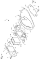
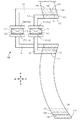
(第3実施例) 図10および図11に、本発明に係る美容機器の第3実施例を示す。本実施例では、肌処理ヘッド2に設けた熱電変換素子15を、その冷熱面17と温熱面16とが左右に指向する状態で配置した点が第2実施例と大きく異なる。他は第2実施例と同じであるので、同じ部材に同じ符号を付してその説明を省略する。肌処理ヘッド2には、センターヘッド(第1熱供給体)30の周囲を囲む状態でラウンドヘッド(第2熱供給体)20を配置してある。 (Third Embodiment) FIGS. 10 and 11 show a third embodiment of a beauty device according to the present invention. The present embodiment is largely different from the second embodiment in that the thermoelectric conversion element 15 provided in the skin treatment head 2 is arranged in a state where the cold surface 17 and the warm surface 16 are directed left and right. Since others are the same as those of the second embodiment, the same reference numerals are assigned to the same members and the description thereof is omitted. In the skin treatment head 2, a round head (second heat supply body) 20 is disposed so as to surround the center head (first heat supply body) 30.

図10および図11に示すように、ラウンドヘッド20が備えるベース壁21の前面の左端側には、熱電変換素子15の冷熱面17と接触して熱を受取る板状の第2伝熱体24が前方に向かって一体に突出形成してあり、第2伝熱体24の右面には、受熱面26が形成してある。これにより、ラウンドヘッド20は、第2伝熱体24を介して熱電変換素子15の冷熱面17と接続されている。第2伝熱体24の受熱面26に伝導した冷熱面17の熱は、ラウンドヘッド20全体を冷却する。ベース壁21には、右端側に断熱筒壁47が挿通される円状の連通開口27が開設してあり、第2伝熱体24のベース壁21の左右端には、締結ビス(第2締結体)44をねじ込むためのねじボス28・28がそれぞれ前方に向かって突設してある。   As shown in FIGS. 10 and 11, on the left end side of the front surface of the base wall 21 provided in the round head 20, a plate-like second heat transfer body 24 that receives heat by contacting the cold surface 17 of the thermoelectric conversion element 15. Are formed so as to project integrally toward the front, and a heat receiving surface 26 is formed on the right surface of the second heat transfer body 24. Thereby, the round head 20 is connected to the cooling surface 17 of the thermoelectric conversion element 15 via the second heat transfer body 24. The heat of the cold surface 17 conducted to the heat receiving surface 26 of the second heat transfer body 24 cools the entire round head 20. The base wall 21 is provided with a circular communication opening 27 through which the heat insulating cylindrical wall 47 is inserted on the right end side, and a fastening screw (second end) is provided at the left and right ends of the base wall 21 of the second heat transfer body 24. Screw bosses 28 and 28 for screwing the fastening body 44 are projected forward.

センターヘッド30は、背面視において横長楕円状に形成した伝熱ベース31と、伝熱ベース31の前面右側に突設される連結軸(伝熱軸部)38とを一体に形成してある。伝熱ベース31の後面は、第1伝熱面34として形成してあり、第1伝熱面34は、左右方向の中央位置が後面に向かって膨らむ凸曲面状に形成してある。   The center head 30 is integrally formed with a heat transfer base 31 formed in an oblong shape in a rear view and a connecting shaft (heat transfer shaft portion) 38 protruding from the front right side of the heat transfer base 31. The rear surface of the heat transfer base 31 is formed as a first heat transfer surface 34, and the first heat transfer surface 34 is formed in a convex curved shape in which the center position in the left-right direction swells toward the rear surface.

第1伝熱体37は、受熱プレート(第1受熱部)39と、受熱プレート39の後端に一体に形成される連結壁65とでL字状に形成してある。連結壁65の後面には締結ボス32が形成してあり、そのリング中央を前後に貫通するように締結穴が形成してある。受熱プレート39の左面は、温熱面16と接触して温熱を受取る受熱面42となっている。   The first heat transfer body 37 is formed in an L shape by a heat receiving plate (first heat receiving portion) 39 and a connecting wall 65 integrally formed at the rear end of the heat receiving plate 39. A fastening boss 32 is formed on the rear surface of the connecting wall 65, and a fastening hole is formed so as to penetrate the center of the ring forward and backward. The left surface of the heat receiving plate 39 is a heat receiving surface 42 that contacts the warm surface 16 and receives the heat.

センターヘッド30の連結軸38には、締結ビス43をねじ込むためのねじ穴が形成してある。連結壁65に形成した締結ボス32に、連結軸38の先端を挿入した状態で、締結穴を介して締結ビス43をねじ穴にねじ込むことにより、センターヘッド30と第1伝熱体37とを一体化できる。これにより、センターヘッド30は、第1伝熱体37を介して熱電変換素子15の温熱面16と接続されている。第1伝熱体37の受熱面42で受取った温熱面16の熱は、センターヘッド30および第1伝熱体37の全体を加熱する。   A screw hole for screwing the fastening screw 43 is formed in the connecting shaft 38 of the center head 30. The center head 30 and the first heat transfer body 37 are connected by screwing the fastening screw 43 into the screw hole through the fastening hole in a state where the tip of the connecting shaft 38 is inserted into the fastening boss 32 formed on the connecting wall 65. Can be integrated. Thereby, the center head 30 is connected to the hot surface 16 of the thermoelectric conversion element 15 via the first heat transfer body 37. The heat of the hot surface 16 received by the heat receiving surface 42 of the first heat transfer body 37 heats the center head 30 and the entire first heat transfer body 37.

断熱ホルダー46は、横臥T字状に形成してあり、四角枠状に形成された断熱枠48と、断熱枠48の後端と一体に形成される枠ベース66と、枠ベース66の左右端に形成される左右一対の締結座51・51とで構成してある。枠ベース66の後面の中央部には、断熱筒壁47が一体に形成してあり、左端には第2伝熱体24を受け入れる開口67が前後に貫通する状態で開設してある。   The heat insulating holder 46 is formed in a horizontal T shape, a heat insulating frame 48 formed in a square frame shape, a frame base 66 formed integrally with a rear end of the heat insulating frame 48, and left and right ends of the frame base 66 And a pair of left and right fastening seats 51, 51. A heat insulating cylindrical wall 47 is integrally formed at the center of the rear surface of the frame base 66, and an opening 67 for receiving the second heat transfer body 24 is opened at the left end so as to penetrate in the front-rear direction.

(第4実施例) 図12および図13に、本発明に係る美容機器の第4実施例を示す。本実施例では、肌処理ヘッド2に温熱生成手段13および冷熱生成手段14をそれぞれ設けた点が第2実施例と大きく異なる。他は第2実施例と同じであるので、同じ部材に同じ符号を付してその説明を省略する。肌処理ヘッド2には、センターヘッド(第1熱供給体)30の周囲を囲む状態でラウンドヘッド(第2熱供給体)20を配置してある。 (Fourth Embodiment) FIGS. 12 and 13 show a fourth embodiment of a beauty device according to the present invention. This embodiment is greatly different from the second embodiment in that the skin heat treatment head 2 is provided with the warm heat generating means 13 and the cold heat generating means 14 respectively. Since others are the same as those of the second embodiment, the same reference numerals are assigned to the same members and the description thereof is omitted. In the skin treatment head 2, a round head (second heat supply body) 20 is disposed so as to surround the center head (first heat supply body) 30.

図12および図13に示すように、温熱生成手段13は、PTCヒーター70で構成してあり、冷熱生成手段14は、熱電変換素子15の冷熱面17で構成してある。熱電変換素子15の温熱面16にはヒートシンク71が配置してあり、温熱面16で生成される温熱は、ヒートシンク71で放熱するようになっている。   As shown in FIGS. 12 and 13, the heat generation means 13 is configured by a PTC heater 70, and the cold heat generation means 14 is configured by a cold surface 17 of the thermoelectric conversion element 15. A heat sink 71 is disposed on the hot surface 16 of the thermoelectric conversion element 15, and the heat generated by the hot surface 16 is radiated by the heat sink 71.

ラウンドヘッド20が備えるベース壁21の右端側には、ベース壁21から湾曲壁22にわたってスリット状の連通開口27が形成してある。これにより、湾曲壁22のカップ開口端に形成される第2伝熱面23は、不連続な楕円リング状になっている。ベース壁21の前面の左端側には、熱電変換素子15の冷熱面17と接触して熱を受取る第2伝熱体24が一体に突出形成してあり、ラウンドヘッド20は、第2伝熱体24を介して熱電変換素子15の冷熱面17と接続されている。第2伝熱体24の受熱面26で受取った冷熱面17の熱は、ラウンドヘッド20全体を冷却する。ベース壁21の中央部には、締結ビス(第2締結体)44がねじ込まれるねじボス28が前方に向かって突設してある。   A slit-shaped communication opening 27 is formed from the base wall 21 to the curved wall 22 on the right end side of the base wall 21 provided in the round head 20. Thereby, the 2nd heat-transfer surface 23 formed in the cup opening end of the curved wall 22 is a discontinuous elliptical ring shape. On the left end side of the front surface of the base wall 21, a second heat transfer body 24 that contacts the cooling surface 17 of the thermoelectric conversion element 15 and receives heat is integrally formed to protrude, and the round head 20 has a second heat transfer function. The thermoelectric conversion element 15 is connected to the cooling surface 17 via the body 24. The heat of the cold surface 17 received by the heat receiving surface 26 of the second heat transfer body 24 cools the entire round head 20. At the center of the base wall 21, a screw boss 28 into which a fastening screw (second fastening body) 44 is screwed is projected forward.

本実施例においては、センターヘッド30と第1伝熱体37を一体に形成した。詳しくは、背面視において横長楕円状に形成した伝熱ベース31と、伝熱ベース31の前面右側に突設される連結軸(伝熱軸部)38と、連結軸38の前端に形成される受熱プレート(第1受熱部)39とを一体に形成してある。伝熱ベース31の後面は、第1伝熱面34として機能しており、第1伝熱面34は平坦な面で形成してある。受熱プレート39の前面は、PTCヒーター70と接触して温熱を受取る受熱面42となっている。PTCヒーター70は、受熱プレート39に取付金具72と固定ビス73とで固定してある。   In the present embodiment, the center head 30 and the first heat transfer body 37 are integrally formed. Specifically, the heat transfer base 31 is formed in a horizontally long oval shape in a rear view, a connecting shaft (heat transfer shaft portion) 38 protruding from the front right side of the heat transfer base 31, and a front end of the connecting shaft 38. A heat receiving plate (first heat receiving portion) 39 is integrally formed. The rear surface of the heat transfer base 31 functions as a first heat transfer surface 34, and the first heat transfer surface 34 is formed as a flat surface. The front surface of the heat receiving plate 39 is a heat receiving surface 42 that contacts the PTC heater 70 and receives the heat. The PTC heater 70 is fixed to the heat receiving plate 39 with a mounting bracket 72 and a fixing screw 73.

断熱ホルダー46は、四角枠状に形成された断熱枠48と、断熱枠48の右枠部に形成されるホルダー腕69と、ホルダー腕69の基部に形成される締結座51とで構成してある。ホルダー腕69には、スリットを設けて3/4円弧状に形成された断熱筒壁47が一体に形成してある。断熱枠48には、ヒートシンク71が固定ビス74で固定してある。   The heat insulating holder 46 includes a heat insulating frame 48 formed in a square frame shape, a holder arm 69 formed on the right frame portion of the heat insulating frame 48, and a fastening seat 51 formed on the base portion of the holder arm 69. is there. The holder arm 69 is integrally formed with a heat insulating cylindrical wall 47 provided with a slit and formed in a 3/4 arc shape. A heat sink 71 is fixed to the heat insulating frame 48 with fixing screws 74.

一体に形成したセンターヘッド30および第1伝熱体37の断熱ホルダー46への固定は、まず、ラウンドヘッド20に断熱ホルダー46を固定する。こののち、連結軸38をラウンドヘッド20の連通開口27に差し込むようにスライドさせながら挿入し、連結軸38を断熱筒壁47部分に配置した状態で、PTCヒーター70を固定する取付金具72とともに、固定ビス73で断熱ホルダー46に固定する。   The center head 30 and the first heat transfer body 37 that are integrally formed are fixed to the heat insulating holder 46 by first fixing the heat insulating holder 46 to the round head 20. Thereafter, the connecting shaft 38 is inserted while being slid so as to be inserted into the communication opening 27 of the round head 20, and the mounting shaft 72 is fixed to the heat insulating cylindrical wall 47 portion, with the mounting bracket 72 for fixing the PTC heater 70, Fix to the heat insulating holder 46 with fixing screws 73.

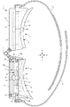
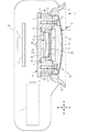
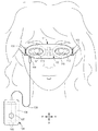
(第5実施例) 図14から図16に、本発明に係る美容機器を目元ケア用の美容機器に適用した第5実施例を示す。本実施例では、目元ヘッド2を目元に固定した状態で前方が視認できるように視認窓76を形成した点と、まぶたと第1伝熱面34とを離間させるためにアジャスト枠77を設けた点が第1実施例と異なっている。他は第1実施例と同じであるので、同じ部材に同じ符号を付してその説明を省略する。 (Fifth Embodiment) FIGS. 14 to 16 show a fifth embodiment in which the beauty device according to the present invention is applied to a beauty device for eye care. In this embodiment, an adjustment frame 77 is provided to separate the eyelid and the first heat transfer surface 34 from the point where the viewing window 76 is formed so that the front can be visually recognized with the eye head 2 fixed to the eye. This is different from the first embodiment. Since others are the same as those of the first embodiment, the same members are denoted by the same reference numerals and the description thereof is omitted.

熱電変換素子15はドーナツ状に構成してあり、その温熱面16および冷熱面17は円リング状に形成されている。アイカップ(第2熱供給体)20には、ベース壁21および第2伝熱体24を前後に貫通するカップ開口78が開設してある。アイプレート(第1熱供給体)30には、伝熱ベース31を前後に貫通するプレート開口79が開設してあり、第1伝熱体37には、受熱プレート39および受熱座41を前後に貫通する伝熱体開口80が開設してある。これら各開口78・79・80と、ドーナツ状に形成した熱電変換素子15とにより、目元ヘッド2には、前後に貫通するヘッド窓81が形成されている。また、前ハウジング10aには、ヘッド窓81に対応してハウジング窓82が開設してあり、これら両窓81・82で目元ヘッド2およびハウジング10を貫通する視認窓76が形成されている。   The thermoelectric conversion element 15 is configured in a donut shape, and its hot surface 16 and cold surface 17 are formed in a circular ring shape. The eye cup (second heat supply body) 20 has a cup opening 78 that penetrates the base wall 21 and the second heat transfer body 24 back and forth. The eye plate (first heat supply body) 30 has a plate opening 79 penetrating the heat transfer base 31 in the front-rear direction, and the first heat transfer body 37 includes a heat-receiving plate 39 and a heat-receiving seat 41 in the front-rear direction. A heat transfer body opening 80 is formed therethrough. A head window 81 penetrating in the front-rear direction is formed in the eye head 2 by the openings 78, 79, 80 and the thermoelectric conversion element 15 formed in a donut shape. The front housing 10 a has a housing window 82 corresponding to the head window 81, and a viewing window 76 penetrating the eye head 2 and the housing 10 is formed by both the windows 81 and 82.

目元ヘッド2を目元に固定した状態で、まぶたを第1伝熱面34から離間させるためのアジャスト枠77が設けてある。アジャスト枠77は、第2伝熱面23に対応した楕円枠状に形成してあり、その前面側には、湾曲壁22のカップ開口縁に嵌合装着するための嵌合凹部83が周回状に凹み形成してある。アジャスト枠77は、カップ開口縁に嵌合凹部83を嵌合させることにより、目元ヘッド2に着脱自在に装着できる。目元ヘッド2にアジャスト枠77を装着することにより、アジャスト枠77がまぶたの周辺の肌面に接触して、まぶたと第1伝熱面34とが離間した状態で、目元ヘッド2を目元に固定することができ、これにより、目を開けて視認窓76から前方を見ることができる。アジャスト枠77は、熱伝導率の高いアルミニウムで形成してあり、装着時に接触する第2伝熱面23を介して熱電変換素子15の冷熱面17と接続され、冷熱面17から伝導された冷熱で、アジャスト枠77を冷却できる。   An adjustment frame 77 for separating the eyelid from the first heat transfer surface 34 in a state where the eye head 2 is fixed to the eye is provided. The adjustment frame 77 is formed in an elliptical frame shape corresponding to the second heat transfer surface 23, and a fitting recess 83 for fitting and mounting on the cup opening edge of the curved wall 22 is formed in a circular shape on the front surface side thereof. A depression is formed on the surface. The adjustment frame 77 can be detachably attached to the eye head 2 by fitting the fitting recess 83 to the cup opening edge. By attaching the adjustment frame 77 to the eye head 2, the adjustment frame 77 comes into contact with the skin surface around the eyelid, and the eyelid 2 and the first heat transfer surface 34 are separated from each other. Thus, the user can open the eyes and see the front from the viewing window 76. The adjustment frame 77 is made of aluminum having a high thermal conductivity, and is connected to the cooling surface 17 of the thermoelectric conversion element 15 via the second heat transfer surface 23 that is in contact with the cooling frame 17. Thus, the adjustment frame 77 can be cooled.

本実施例の目元ケア用の美容機器においては、アジャスト枠77を装着しない状態では、プレート開口79の周囲の第1伝熱面34および第2伝熱面23で、眼球およびまぶたの周辺の肌面に異なる温度の熱刺激を与えて、美容効果を発揮することができる。また、アジャスト枠77を装着した状態では、まぶたが第1伝熱面34から離間するので、目を開けて視認窓76から前方を見ることができる。これにより、テレビや本等を見ながらまぶたの周辺の肌面に冷熱刺激を与えて、美容効果を発揮することができる。   In the cosmetic device for eye care according to the present embodiment, the skin around the eyeball and the eyelids at the first heat transfer surface 34 and the second heat transfer surface 23 around the plate opening 79 when the adjustment frame 77 is not attached. It is possible to exert a beauty effect by applying thermal stimulation at different temperatures to the surface. Further, when the adjustment frame 77 is attached, the eyelid is separated from the first heat transfer surface 34, so that the eyes can be opened and the front can be seen from the viewing window 76. Thereby, it is possible to exert a beauty effect by applying a cold stimulus to the skin surface around the eyelid while watching a television or a book.

上記の第1から第5実施例では、第1伝熱面34を楕円状に形成したが、円状や多角形状に形成することができる。第2伝熱面23は楕円リング状である必要はなく、円形リング状、多角形リング状、あるいは直線と曲線を組み合わせた枠状などに適宜形成することができる。また、第2伝熱面23は連続した面である必要はなく、断続的に形成して第1伝熱面34の周囲を囲むようにしてもよい。   In the first to fifth embodiments described above, the first heat transfer surface 34 is formed in an elliptical shape, but can be formed in a circular shape or a polygonal shape. The second heat transfer surface 23 does not need to have an elliptical ring shape, and can be appropriately formed in a circular ring shape, a polygonal ring shape, or a frame shape in which straight lines and curves are combined. Further, the second heat transfer surface 23 does not have to be a continuous surface, and may be formed intermittently to surround the first heat transfer surface 34.

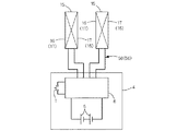
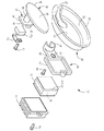
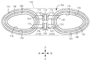
(第6実施例) 図17から図20に、本発明に係る美容機器を目元ケア用の美容機器に適用した第6実施例を示す。図18において美容機器は、両目元部を覆うように形成される本体部101と、本体部101に固定される目元ヘッド(肌処理ヘッド)102と、本体部101を頭部に固定する固定バンド103と、本体部101とは別体に構成されて、後述する温熱生成手段113および冷熱生成手段114に駆動電流を供給し制御するコントローラ104などで構成する。コントローラ104は、電源となる電池105と、温熱生成手段113および冷熱生成手段114に供給される駆動電流を生成し制御する制御基板(制御手段)106と、制御基板106の動作を切換えるスイッチ107などを備えている。 (Sixth Embodiment) FIGS. 17 to 20 show a sixth embodiment in which the beauty device according to the present invention is applied to a beauty device for eye care. In FIG. 18, the beauty device includes a main body 101 formed so as to cover both eyes, an eye head (skin treatment head) 102 fixed to the main body 101, and a fixing band for fixing the main body 101 to the head. 103 and the main body 101 are configured separately from each other, and include a controller 104 that supplies and controls drive current to a heat generation unit 113 and a cold generation unit 114, which will be described later. The controller 104 includes a battery 105 serving as a power source, a control board (control means) 106 that generates and controls drive current supplied to the heat generation means 113 and the cold generation means 114, a switch 107 that switches the operation of the control board 106, and the like. It has.

図18および図19に示すように、本体部101は、左右に長い長円状のハウジング110で構成されており、ハウジング110には、前後に貫通する左右一対のハウジング窓112が形成してある。本体部101は、ハウジング110の外側に連結した左右一対の固定バンド103・103で頭部に装着できるようになっており、後頭部側で一方の固定バンド103に縫着した雌側の面ファスナーに、他方の固定バンド103に縫着した雄側の面ファスナーを固定して頭部に装着することができる。   As shown in FIGS. 18 and 19, the main body 101 is composed of an oblong housing 110 that is long on the left and right, and the housing 110 has a pair of left and right housing windows 112 penetrating in the front-rear direction. . The main body 101 can be attached to the head with a pair of left and right fixing bands 103 and 103 connected to the outside of the housing 110, and is attached to a female surface fastener that is sewn to one fixing band 103 on the rear head side. The male hook-and-loop fastener sewn on the other fixing band 103 can be fixed and attached to the head.

図19および図20に示すように、目元ヘッド102は、温熱生成手段113および冷熱生成手段114と、温熱生成手段113または冷熱生成手段114で生成された熱を肌面に伝導する内リング体(第1熱供給体)130と、冷熱生成手段114または温熱生成手段113で生成された熱を肌面に伝導する外リング体(第2熱供給体)120とを含んで構成してある。外リング体120および内リング体130は、ハウジング110の左右に1対ずつ設けてある。   As shown in FIGS. 19 and 20, the eye head 102 includes a heat generation unit 113 and a cold heat generation unit 114, and an inner ring body that conducts heat generated by the heat generation unit 113 or the cold heat generation unit 114 to the skin surface ( (First heat supply body) 130 and an outer ring body (second heat supply body) 120 that conducts heat generated by the cold heat generation means 114 or the heat generation means 113 to the skin surface. The outer ring body 120 and the inner ring body 130 are provided in pairs on the left and right sides of the housing 110.

図20に示すように、内リング体130および外リング体120は、正面視において卵型の環状に形成してあり、それぞれに前後に貫通する窓118・119が形成してある。内リング体130と外リング体120とは径の異なる相似形状に形成してあり、両リング体130・120は同心状に配置してある。両リング体130・120は、外リング体120の窓119の内方空間に、内リング体130が隙間を介して対向する状態で配置してある。これにより、外リング体120は内リング体130の周囲を囲む状態で配置されている。このように、両リング体130・120を同心状に配置すると、まぶたの周囲の肌面に対して同心状に異なる熱刺激を与えることができる。   As shown in FIG. 20, the inner ring body 130 and the outer ring body 120 are formed in an egg-shaped ring shape in a front view, and windows 118 and 119 penetrating in the front-rear direction are formed. The inner ring body 130 and the outer ring body 120 are formed in similar shapes having different diameters, and both the ring bodies 130 and 120 are arranged concentrically. Both ring bodies 130 and 120 are disposed in the inner space of the window 119 of the outer ring body 120 with the inner ring body 130 facing each other with a gap. As a result, the outer ring body 120 is disposed so as to surround the inner ring body 130. Thus, when both ring bodies 130 and 120 are arranged concentrically, different thermal stimuli can be applied concentrically to the skin surface around the eyelid.

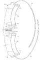
内リング体130と外リング体120との隙間には、両リング体130・120間の熱移動を阻止する断熱枠体(スペーサー)146が配置してある。断熱枠体146は、両リング体130・120を保持する保持体を兼ねている。内リング体130の後端面には第1伝熱面134が設けてあり、外リング体120の後端面には第2伝熱面123が設けてある。両伝熱面134・123は、それぞれ卵型の楕円リング状に形成してあり、断熱枠体146の後端面と、第1および第2の伝熱面134・123は、面一状に形成してある。   In the gap between the inner ring body 130 and the outer ring body 120, a heat insulating frame (spacer) 146 that prevents heat transfer between the ring bodies 130 and 120 is disposed. The heat insulating frame 146 also serves as a holding body that holds both the ring bodies 130 and 120. A first heat transfer surface 134 is provided on the rear end surface of the inner ring body 130, and a second heat transfer surface 123 is provided on the rear end surface of the outer ring body 120. Both the heat transfer surfaces 134 and 123 are each formed in an oval elliptical ring shape, and the rear end surface of the heat insulating frame 146 and the first and second heat transfer surfaces 134 and 123 are formed in the same plane. It is.

温熱生成手段113および冷熱生成手段114は1個の熱電変換素子115で構成してあり、その温熱を生成する温熱面116と、冷熱を生成する冷熱面117とが、それぞれ温熱生成手段113および冷熱生成手段114として機能する。目元ヘッド102には、2個の熱電変換素子115が設けてあり、各熱電変換素子115が上下に並ぶように配置してある。なお、図17および図19では、構成を理解しやすくするために、各熱電変換素子115が前後に位置をずらした状態で記載してある。熱電変換素子115は、各面116・117が左右に指向する状態で配置してあり、制御基板106で熱電変換素子115に順方向の駆動電流を供給したとき、一方の熱電変換素子115の右面側が温熱を生成する温熱面116の場合には、他方の熱電変換素子115の右面側が冷熱を生成する冷熱面117になるように、各熱電変換素子115の向きを逆に配置してある。本実施例では、上側の熱電変換素子115の右面および下側の熱電変換素子115の左面が冷熱面117となるように配置した。熱電変換素子115の接続リードは、ハウジング110に設けた入力端子157(図18参照)に接続してあり、入力端子157に給電リード158の先端のプラグ159を差し込むことで、コントローラ104から熱電変換素子115に駆動電流を供給することができる。   The hot heat generating means 113 and the cold heat generating means 114 are configured by one thermoelectric conversion element 115, and the hot surface 116 that generates the hot heat and the cold surface 117 that generates the cold are respectively the hot heat generating means 113 and the cold heat. It functions as the generation means 114. The eye head 102 is provided with two thermoelectric conversion elements 115, and the thermoelectric conversion elements 115 are arranged in the vertical direction. In FIG. 17 and FIG. 19, each thermoelectric conversion element 115 is illustrated in a state where the position is shifted back and forth for easy understanding of the configuration. The thermoelectric conversion element 115 is arranged in a state where the surfaces 116 and 117 are directed left and right. When a forward drive current is supplied to the thermoelectric conversion element 115 by the control board 106, the right surface of one of the thermoelectric conversion elements 115 is arranged. In the case of the hot surface 116 that generates warm heat on the side, the direction of each thermoelectric conversion element 115 is reversed so that the right surface side of the other thermoelectric conversion element 115 becomes the cold surface 117 that generates cold heat. In the present example, the right surface of the upper thermoelectric conversion element 115 and the left surface of the lower thermoelectric conversion element 115 are arranged to be the cooling surface 117. The connection lead of the thermoelectric conversion element 115 is connected to an input terminal 157 (see FIG. 18) provided in the housing 110. By inserting a plug 159 at the tip of the power supply lead 158 into the input terminal 157, thermoelectric conversion is performed from the controller 104. A driving current can be supplied to the element 115.

上記のように、温熱生成手段113および冷熱生成手段114を1個の熱電変換素子115で構成すると、温熱生成手段113と冷熱生成手段114を個別に設ける場合に比べて、熱生成構造を簡素化して美容機器の製造に要するコストを削減できる。また、熱電変換素子115で生成される温熱と冷熱の双方を利用するので、熱電変換素子115で生成した温熱と冷熱を無駄なく有効に活用できる。   As described above, when the heat generation means 113 and the cold heat generation means 114 are configured by one thermoelectric conversion element 115, the heat generation structure is simplified as compared with the case where the heat generation means 113 and the cold heat generation means 114 are provided separately. This reduces the cost of manufacturing beauty equipment. Further, since both the hot and cold generated by the thermoelectric conversion element 115 are used, the hot and cold generated by the thermoelectric conversion element 115 can be effectively used without waste.

外リング体120は、冷熱面117で生成された熱を伝導するL字状の第2伝熱体124を一体に備えている。第2伝熱体124の一端には、冷熱面117と接触して冷熱を受取る受熱面126が形成してあり、冷熱面117と受熱面126とは、シリコーンゴム製の伝熱シートを介して密着させて、熱の伝導効率を向上させている。このように、外リング体120は、第2伝熱体124を介して熱電変換素子115の冷熱面117と接続されているので、冷熱面117から伝導された冷熱で、外リング体120の全体を冷却できる。   The outer ring body 120 is integrally provided with an L-shaped second heat transfer body 124 that conducts heat generated on the cold surface 117. One end of the second heat transfer body 124 is formed with a heat receiving surface 126 that contacts the cold heat surface 117 and receives the cold heat, and the cold heat surface 117 and the heat receiving surface 126 are interposed via a heat transfer sheet made of silicone rubber. It is closely attached to improve heat conduction efficiency. Thus, since the outer ring body 120 is connected to the cold surface 117 of the thermoelectric conversion element 115 via the second heat transfer body 124, the entire outer ring body 120 is cooled by the cold conducted from the cold surface 117. Can be cooled.

同様に、内リング体130は、温熱面116で生成された熱を伝導するL字状の第1伝熱体137を一体に備えている。第1伝熱体137の一端には、温熱面116と接触して温熱を受取る受熱面142が形成してあり、温熱面116と受熱面142とは、シリコーンゴム製の伝熱シートを介して密着させて、熱の伝導効率を向上させている。このように、内リング体130は、第1伝熱体137を介して熱電変換素子115の温熱面116と接続されているので、温熱面116から伝導された温熱で、内リング体130の全体を加熱できる。   Similarly, the inner ring body 130 is integrally provided with an L-shaped first heat transfer body 137 that conducts heat generated on the hot surface 116. One end of the first heat transfer body 137 is formed with a heat receiving surface 142 that contacts the hot surface 116 and receives the heat, and the hot surface 116 and the heat receiving surface 142 are interposed via a heat transfer sheet made of silicone rubber. It is closely attached to improve heat conduction efficiency. Thus, since the inner ring body 130 is connected to the hot surface 116 of the thermoelectric conversion element 115 via the first heat transfer body 137, the entire inner ring body 130 is heated by the heat conducted from the hot surface 116. Can be heated.

外リング体130、および内リング体120は、アルミニウム、真鍮、銅などの熱伝導率の高い金属材料を素材として形成することができる。本実施例では、アルミニウムを素材としたダイキャスト成形品に切削加工を施して、先の各部材120・130を形成した。熱伝導率の高いアルミニウムを素材として外リング体130、および内リング体120を形成するので、それぞれの全体に素早く熱を伝導して、より短い時間で所定の温度に冷却および加熱することができる。   The outer ring body 130 and the inner ring body 120 can be formed using a metal material having high thermal conductivity such as aluminum, brass, or copper as a raw material. In this embodiment, the die-cast molded product made of aluminum was cut to form the respective members 120 and 130. Since the outer ring body 130 and the inner ring body 120 are formed using aluminum having a high thermal conductivity as a raw material, it is possible to conduct heat quickly to the whole and cool and heat to a predetermined temperature in a shorter time. .

目元ヘッド102に設けられる左右1対の外リング体120、内リング体130、および断熱枠体146は、同一部材で構成してある。目元ヘッド102は、断熱枠体146に設けた図示しない固定部がハウジング110に図示しない締結ビスで締結されて、ハウジング110と一体に固定される。目元ヘッド102をハウジング110に固定した状態では、ハウジング110に形成した左右一対のハウジング窓112と、各内リング体130の窓118とが対向している。これにより、目元ヘッド2を目元に装着した状態においては、窓118・119を介してハウジング窓112から前方を視認することができる。   The pair of left and right outer ring bodies 120, inner ring body 130, and heat insulating frame body 146 provided on the eye head 102 are made of the same member. The eye head 102 is fixed integrally with the housing 110 by fastening a fixing portion (not shown) provided on the heat insulating frame 146 to the housing 110 with a fastening screw (not shown). In a state where the eye head 102 is fixed to the housing 110, a pair of left and right housing windows 112 formed in the housing 110 and the windows 118 of the inner ring bodies 130 face each other. Thereby, in a state where the eye head 2 is attached to the eye, the front can be visually recognized from the housing window 112 through the windows 118 and 119.

ここで、目元ケア用の美容機器の使用方法を説明する。まず、外リング体130および内リング体120を目元に装着する。詳しくは、左右の第1伝熱面134および第2伝熱面123が、まぶたの周辺の肌面に接触するように本体部101を目元にあてがい、左右の固定バンド103・103を後頭部側で重ねて、面ファスナーで固定する。コントローラ104のスイッチ107を押下すると、制御基板106が各熱電変換素子115に順方向の駆動電流を供給し、各温熱面116および冷熱面117で温熱と冷熱が生成される。温熱面116で生成された温熱は、第1伝熱体137を介して内リング体130に伝導され、その第1伝熱面134で接触する肌面に温熱刺激を与える。また、冷熱面117で生成された冷熱は、第2伝熱体124を介して外リング体120に伝導され、その第2伝熱面123で接触する肌面に冷熱刺激を与える。これにより、まぶたの周辺の肌面に異なる温度の熱刺激を与えて、美容効果を発揮することができる。このとき、窓118・119を介してハウジング窓112から前方を視認できるので、テレビや本をみながら肌面に熱刺激を与えることができる。制御基板106が供給する駆動電流は、予め設定された時間が経過し、あるいは再度スイッチ107を押下することで停止し、これにより熱刺激の付与が終了する。   Here, a method of using a beauty device for eye care will be described. First, the outer ring body 130 and the inner ring body 120 are attached to the eyes. Specifically, the main body 101 is applied to the eyes so that the left and right first heat transfer surfaces 134 and the second heat transfer surface 123 are in contact with the skin surface around the eyelids, and the left and right fixing bands 103 and 103 are disposed on the back of the head. Stack and fix with hook-and-loop fasteners. When the switch 107 of the controller 104 is pressed, the control board 106 supplies a driving current in the forward direction to each thermoelectric conversion element 115, and hot and cold are generated on the hot and cold surfaces 116 and 117. The warm heat generated on the warm surface 116 is conducted to the inner ring body 130 via the first heat transfer body 137 and gives a thermal stimulus to the skin surface in contact with the first heat transfer surface 134. In addition, the cold generated on the cold surface 117 is conducted to the outer ring body 120 via the second heat transfer body 124 and gives a cold stimulus to the skin surface in contact with the second heat transfer surface 123. Thereby, the thermal effect of different temperature can be given to the skin surface around the eyelid, and the beauty effect can be exhibited. At this time, since the front can be visually recognized from the housing window 112 through the windows 118 and 119, the skin surface can be thermally stimulated while watching a television or a book. The drive current supplied by the control board 106 is stopped when a preset time elapses or when the switch 107 is pressed again, whereby the application of thermal stimulation is completed.

上記の第6実施例においても、制御基板106で熱電変換素子115に供給する駆動電流の極性を、所定時間ごとに反転して交互に供給することができる。このように、所定時間ごとに駆動電流の極性を反転させることで、目元ヘッド2を目元部分に装着した状態のままで、まぶたの周辺の肌面に冷熱刺激と温熱刺激を交互に与えて、美容効果を発揮することができる。   Also in the sixth embodiment, the polarity of the drive current supplied to the thermoelectric conversion element 115 by the control board 106 can be reversed and supplied alternately every predetermined time. In this way, by reversing the polarity of the drive current every predetermined time, with the eye head 2 attached to the eye area, the heat stimulus and the heat stimulus are alternately applied to the skin surface around the eyelid, The beauty effect can be demonstrated.

(第7実施例) 図21に、本発明に係る美容機器の第7実施例を示す。本実施例では、ハウジング110の左右に第1熱供給体130と第2熱供給体120を各1個ずつ設けた点と、熱電変換素子を1個とした点と、熱電変換素子115に供給される駆動電流の極性を、所定時間ごとに反転する点が第6実施例と異なる。他は第6実施例と同じであるので、同じ部材に同じ符号を付してその説明を省略する。 (Seventh Embodiment) FIG. 21 shows a seventh embodiment of a beauty device according to the present invention. In this embodiment, the first heat supply body 130 and the second heat supply body 120 are provided on the left and right sides of the housing 110, the thermoelectric conversion element is one, and the thermoelectric conversion element 115 is supplied. This embodiment is different from the sixth embodiment in that the polarity of the drive current to be reversed is reversed every predetermined time. Since others are the same as in the sixth embodiment, the same reference numerals are assigned to the same members, and descriptions thereof are omitted.

ハウジング110には、右目用リング体(第1熱供給体)130と、左目用リング体(第2熱供給体)120とが固定してある。熱電変換素子115は、温熱面116と冷熱面117とが左右に指向する状態で配置してあり、制御基板106で熱電変換素子115に順方向の駆動電流を供給したとき、熱電変換素子115の右面側が温熱を生成する温熱面116として機能させ、左面側が冷熱を生成する冷熱面117として機能させることができる。   A right-eye ring body (first heat supply body) 130 and a left-eye ring body (second heat supply body) 120 are fixed to the housing 110. The thermoelectric conversion element 115 is arranged in a state where the hot and cold surfaces 116 and 117 are directed left and right, and when a forward drive current is supplied to the thermoelectric conversion element 115 by the control board 106, the thermoelectric conversion element 115 The right surface side can function as the heating surface 116 that generates heat, and the left surface side can function as the cooling surface 117 that generates cooling.

左目用リング体120の第2伝熱体124の受熱面126は、シリコーンゴム製の伝熱シートを介して冷熱面117と接続してあり、冷熱面117から伝導された冷熱で、左目用リング体120の全体を冷却できる。また、右目用リング体130の第1伝熱体137の受熱面142は、シリコーンゴム製の伝熱シートを介して温熱面116と接続してあり、温熱面116から伝導された温熱で、右目用リング体130の全体を加熱できる。これにより、左のまぶたの周辺の肌面に冷熱刺激を与え、右のまぶたの周辺の肌面に温熱刺激を与えて、美容効果を発揮することができる。このとき、窓118・119を介してハウジング窓112から前方を視認できるので、テレビや本をみながら肌面に熱刺激を与えることができる。   The heat-receiving surface 126 of the second heat transfer body 124 of the left-eye ring body 120 is connected to the cooling surface 117 via a heat transfer sheet made of silicone rubber, and the left-eye ring is cooled by the heat transferred from the cooling surface 117. The entire body 120 can be cooled. Further, the heat receiving surface 142 of the first heat transfer body 137 of the right-eye ring body 130 is connected to the heating surface 116 via a heat transfer sheet made of silicone rubber, and the right eye is heated by the heat conducted from the heating surface 116. The entire ring body 130 can be heated. Thereby, a cold stimulus is given to the skin surface around the left eyelid, and a thermal stimulus is given to the skin surface around the right eyelid, so that a beauty effect can be exhibited. At this time, since the front can be visually recognized from the housing window 112 through the windows 118 and 119, the skin surface can be thermally stimulated while watching a television or a book.

制御基板106は、熱電変換素子115に供給する駆動電流の極性を所定時間ごとに反転して交互に供給するようになっている。このように、所定時間ごとに駆動電流の極性を反転させることで、右目用リング体130と、左目用リング体120による熱刺激態様を、温熱刺激態様と冷熱刺激態様とに交互に切換えるようにすることができる。従って、美容機器の構成を簡素化しながら、まぶた周囲の肌面に異なる温度刺激を交互に与えて、美容効果を発揮することができる。また、窓118・119を介してハウジング窓112から前方を視認できるので、テレビや本をみながら肌面に熱刺激を与えることができる。   The control board 106 is configured to alternately supply the polarity of the drive current supplied to the thermoelectric conversion element 115 by reversing the polarity every predetermined time. In this way, by reversing the polarity of the drive current every predetermined time, the thermal stimulation mode by the right-eye ring body 130 and the left-eye ring body 120 is alternately switched between the thermal stimulation mode and the thermal stimulation mode. can do. Therefore, while simplifying the configuration of the beauty device, different temperature stimuli can be alternately applied to the skin surface around the eyelids to exert a beauty effect. Moreover, since the front can be visually recognized from the housing window 112 through the windows 118 and 119, heat stimulation can be given to the skin surface while watching a television or a book.

第6および第7実施例では、第1伝熱面134および第2伝熱面123を楕円リング状に形成したが、円形リング状、多角形リング状、あるいは直線と曲線を組み合わせた枠状などに適宜形成することができる。また、第1伝熱面134および第2伝熱面123は連続した面である必要はなく、断続的に形成してもよい。   In the sixth and seventh embodiments, the first heat transfer surface 134 and the second heat transfer surface 123 are formed in an elliptical ring shape, but a circular ring shape, a polygonal ring shape, a frame shape in which straight lines and curves are combined, or the like. It can be suitably formed. Further, the first heat transfer surface 134 and the second heat transfer surface 123 need not be continuous surfaces, and may be formed intermittently.

上記の窓118・119を備えた目元ケア用の美容機器は、以下の形態で実施することができる。
肌処理ヘッド102は、温熱生成手段113および冷熱生成手段114と、温熱生成手段113または冷熱生成手段114で生成された熱を肌面に伝導する第1熱供給体130と、冷熱生成手段114または温熱生成手段113で生成された熱を肌面に伝導する第2熱供給体120とを含み、
第1熱供給体130および第2熱供給体120のそれぞれには、前後に貫通する窓118・119が形成されており、
第1熱供給体130および第2熱供給体120を目元に装着して肌面に熱を伝導する状態において、第1熱供給体130および第2熱供給体120の窓118・119を介して前方が視認可能に構成してある目元ケア用の美容機器。
The cosmetic device for eye care provided with the windows 118 and 119 can be implemented in the following manner.
The skin treatment head 102 includes a heat generation unit 113 and a cold heat generation unit 114, a first heat supply body 130 that conducts heat generated by the heat generation unit 113 or the cold heat generation unit 114 to the skin surface, and a cold heat generation unit 114 or A second heat supply body 120 that conducts heat generated by the heat generation means 113 to the skin surface,
Each of the first heat supply body 130 and the second heat supply body 120 is formed with windows 118 and 119 penetrating in the front-rear direction.
In a state where the first heat supply body 130 and the second heat supply body 120 are attached to the eyes and heat is conducted to the skin surface, the windows 118 and 119 of the first heat supply body 130 and the second heat supply body 120 are used. A beauty device for eye care that is visible in the front.

第1熱供給体130および第2熱供給体120はそれぞれ環状に形成されて、前後に貫通する窓118・119が形成されており、
第1熱供給体130と第2熱供給体120とが同心状に配設してある。
The first heat supply body 130 and the second heat supply body 120 are each formed in an annular shape, and have windows 118 and 119 penetrating in the front-rear direction.
The first heat supply body 130 and the second heat supply body 120 are arranged concentrically.

温熱生成手段113および冷熱生成手段114が1個の熱電変換素子115で構成されており、
左右いずれか一方の目元に第1熱供給体130が装着され、残る他方の目元に第2熱供給体120が装着されるようになっており、
熱電変換素子115は、制御手段106で作動状態が制御されるようになっており、
熱電変換素子115に供給される駆動電流の極性を、制御手段106で所定時間ごとに反転して、第1熱供給体130および第2熱供給体120による熱刺激態様を、温熱刺激態様と冷熱刺激態様とに交互に切換えるように構成してある。
The hot heat generating means 113 and the cold heat generating means 114 are composed of one thermoelectric conversion element 115,
The first heat supply body 130 is attached to one of the left and right eyes, and the second heat supply body 120 is attached to the remaining other eye,
The operation state of the thermoelectric conversion element 115 is controlled by the control means 106,
The polarity of the drive current supplied to the thermoelectric conversion element 115 is reversed every predetermined time by the control means 106, and the thermal stimulation mode by the first heat supply body 130 and the second heat supply body 120 is changed between the thermal stimulation mode and the cooling temperature. It is configured to switch alternately to the stimulation mode.

上記の各実施例では、冷温の熱刺激は温度差があればよく、例えば冷熱刺激側を35℃に設定し、温熱刺激側を45℃に設定してもよい。この場合には両熱刺激は共に肌面を加熱する。第1熱供給体30・130、第2熱供給体20・120、および第1伝熱体37などは、アルミニウムで形成したが、真鍮、銅などで形成できる。この場合には、ダイキャスト品に切削加工を施したのち、その表面にメッキや蒸着などでアルミニウムの金属皮膜を形成すればよい。   In each of the above embodiments, it is sufficient that the thermal stimulus of the cold temperature has a temperature difference. For example, the cold stimulus side may be set to 35 ° C. and the warm stimulus side may be set to 45 ° C. In this case, both thermal stimuli heat the skin surface. The first heat supply bodies 30 and 130, the second heat supply bodies 20 and 120, the first heat transfer body 37, and the like are formed of aluminum, but can be formed of brass, copper, or the like. In this case, after the die-cast product is cut, an aluminum metal film may be formed on the surface by plating or vapor deposition.

2 肌処理ヘッド(目元ヘッド)
6 制御手段(制御基板)
13 温熱生成手段
14 冷熱生成手段
15 熱電変換素子
16 温熱面
17 冷熱面
20 第2熱供給体(アイカップ・ラウンドヘッド)
21 ベース壁
22 湾曲壁
23 第2伝熱面
24 第2伝熱体
27 連通開口
30 第1熱供給体(アイプレート・センターヘッド)
34 第1伝熱面
37 第1伝熱体
38 伝熱軸部(連結軸)
39 第1受熱部(受熱プレート)
43 第1締結体(締結ビス)
44 第2締結体(締結ビス)
46 スペーサー(断熱ホルダー)
47 断熱筒壁
S 断熱空間
2 Skin treatment head (eye head)
6 Control means (control board)
13 Thermal generation means 14 Cold generation means 15 Thermoelectric conversion element 16 Hot surface 17 Cold surface 20 Second heat supply body (eye cup round head)
21 Base wall 22 Curved wall 23 2nd heat transfer surface 24 2nd heat transfer body 27 Communication opening 30 1st heat supply body (eye plate center head)
34 1st heat-transfer surface 37 1st heat-transfer body 38 Heat-transfer shaft part (connection shaft)
39 1st heat receiving part (heat receiving plate)
43 First fastening body (fastening screw)
44 Second fastening body (fastening screw)
46 Spacer (Insulation holder)
47 Insulated cylinder wall S Insulated space

Claims (14)

肌処理ヘッド(2)に、温熱生成手段(13)および冷熱生成手段(14)と、温熱生成手段(13)または冷熱生成手段(14)で生成された熱を肌面に伝導する第1熱供給体(30)と、冷熱生成手段(14)または温熱生成手段(13)で生成された熱を肌面に伝導する第2熱供給体(20)とが設けられており、
第2熱供給体(20)が、第1熱供給体(30)の周囲を囲む状態で配置してあることを特徴とする美容機器。
The heat treatment means (13), the cold heat generation means (14), and the first heat that conducts the heat generated by the heat generation means (13) or the cold heat generation means (14) to the skin treatment head (2). A supply body (30) and a second heat supply body (20) that conducts heat generated by the cold heat generation means (14) or the heat generation means (13) to the skin surface;
The beauty device, wherein the second heat supply body (20) is arranged in a state of surrounding the first heat supply body (30).
第2熱供給体(20)が、肌面との接触部分の側へ向かって開口するカップ形状に形成してある請求項1に記載の美容機器。   The beauty device according to claim 1, wherein the second heat supply body (20) is formed in a cup shape that opens toward a contact portion with the skin surface. 第2熱供給体(20)が、ベース壁(21)と、ベース壁(21)に連続して形成される湾曲壁(22)とを備えており、
湾曲壁(22)が、カップ開口縁へ向かって徐々に拡開するラッパ状に形成してある請求項2に記載の美容機器。
The second heat supply body (20) includes a base wall (21) and a curved wall (22) formed continuously with the base wall (21),
The cosmetic device according to claim 2, wherein the curved wall (22) is formed in a trumpet shape that gradually expands toward the cup opening edge.
第1熱供給体(30)に肌面と接触する第1伝熱面(34)が設けられており、
第1伝熱面(34)が、第2熱供給体(20)のカップ開口縁の第2伝熱面(23)よりカップ内奥側へ凹んだ位置に配置してある請求項2または3に記載の美容機器。
A first heat transfer surface (34) in contact with the skin surface is provided on the first heat supply body (30);
The first heat transfer surface (34) is disposed at a position recessed from the second heat transfer surface (23) of the cup opening edge of the second heat supply body (20) toward the inner side of the cup. Beauty equipment described in.
温熱生成手段(13)または冷熱生成手段(14)と第1熱供給体(30)とが、第1伝熱体(37)を介して熱移動可能に接続されており、
冷熱生成手段(14)または温熱生成手段(13)と第2熱供給体(20)とが、第2伝熱体(24)を介して熱移動可能に接続されており、
第1伝熱体(37)と第2伝熱体(24)との間に、両伝熱体(37・24)の間の熱移動を阻止するスペーサー(46)が配置してある請求項1から4のいずれかひとつに記載の美容機器。
The heat generating means (13) or the cold heat generating means (14) and the first heat supply body (30) are connected to each other through the first heat transfer body (37) so as to be capable of transferring heat,
The cold heat generating means (14) or the warm heat generating means (13) and the second heat supply body (20) are connected via the second heat transfer body (24) so as to be capable of transferring heat,
A spacer (46) is disposed between the first heat transfer body (37) and the second heat transfer body (24) to prevent heat transfer between the heat transfer bodies (37, 24). The beauty device according to any one of 1 to 4.
第2熱供給体(20)のベース壁(21)に形成した連通開口(27)に断熱筒壁(47)が配置されており、
第1伝熱体(37)が前記断熱筒壁(47)の内部空間を介して第1熱供給体(30)に接続してある請求項5に記載の美容機器。
A heat insulating cylindrical wall (47) is disposed in the communication opening (27) formed in the base wall (21) of the second heat supply body (20),
The beauty device according to claim 5, wherein the first heat transfer body (37) is connected to the first heat supply body (30) through an internal space of the heat insulating cylindrical wall (47).
前記断熱筒壁(47)が前記スペーサー(46)と一体に形成してある請求項6に記載の美容機器。   The beauty device according to claim 6, wherein the heat insulating cylindrical wall (47) is formed integrally with the spacer (46). 第1伝熱体(37)と前記断熱筒壁(47)との間に、断熱空間(S)が形成してある請求項6から7のいずれかひとつに記載の美容機器。   The beauty device according to any one of claims 6 to 7, wherein a heat insulating space (S) is formed between the first heat transfer body (37) and the heat insulating cylindrical wall (47). 第2熱供給体(20)の外面に配置したスペーサー(46)が、第2締結体(44)で第2熱供給体(20)に締結固定されており、
第1伝熱体(37)が、前記断熱筒壁(47)に挿通される伝熱軸部(38)と、温熱生成手段(13)または冷熱生成手段(14)に接触する第1受熱部(39)とを一体に備えており、
第1伝熱体(37)は、その第1受熱部(39)が位置決めされた状態でスペーサー(46)に接合されて、伝熱軸部(38)が前記断熱筒壁(47)を前後に貫通しており、
伝熱軸部(38)にねじ込んだ第1締結体(43)で、第1熱供給体(30)と第1伝熱体(37)とを締結固定した状態において、伝熱軸部(38)と前記断熱筒壁(47)との間に筒状の断熱空間(S)が形成してある請求項8に記載の美容機器。
The spacer (46) disposed on the outer surface of the second heat supply body (20) is fastened and fixed to the second heat supply body (20) by the second fastening body (44),
The first heat transfer body (37) is in contact with the heat transfer shaft (38) inserted through the heat insulating cylindrical wall (47) and the heat generation means (13) or the cold heat generation means (14). (39) and
The first heat transfer body (37) is joined to the spacer (46) in a state where the first heat receiving section (39) is positioned, and the heat transfer shaft section (38) moves back and forth along the heat insulating cylindrical wall (47). And penetrates
In a state where the first heat supply body (30) and the first heat transfer body (37) are fastened and fixed by the first fastening body (43) screwed into the heat transfer shaft section (38), the heat transfer shaft section (38 ) And the heat insulating cylindrical wall (47), a cylindrical heat insulating space (S) is formed.
温熱生成手段(13)および冷熱生成手段(14)が1個の熱電変換素子(15)で構成されており、
第1熱供給体(30)は、熱電変換素子(15)の温熱面(16)と冷熱面(17)とのいずれか一方と第1伝熱体(37)を介して接続されており、
第2熱供給体(20)は、熱電変換素子(15)の冷熱面(17)と温熱面(16)とのいずれか一方と第2伝熱体(24)を介して接続されており、
第1熱供給体(30)が、環状に形成した第2熱供給体(20)の内部に配置してある請求項5から9のいずれかひとつに記載の美容機器。
The heat generation means (13) and the cold heat generation means (14) are composed of one thermoelectric conversion element (15),
The first heat supply body (30) is connected to one of the hot surface (16) and the cold surface (17) of the thermoelectric conversion element (15) via the first heat transfer body (37),
The second heat supply body (20) is connected to one of the cold surface (17) and the hot surface (16) of the thermoelectric conversion element (15) via the second heat transfer body (24),
The beauty device according to any one of claims 5 to 9, wherein the first heat supply body (30) is arranged inside a second heat supply body (20) formed in an annular shape.
肌処理ヘッド(2)に、まぶたを介して眼球に熱刺激を付与する第1熱供給体(30)と、まぶたの周辺の肌面に熱刺激を付与する第2熱供給体(20)とが設けられており、
まぶたおよびまぶたの周辺の肌面に熱刺激を与える目元ケア用の美容機器として構成してある請求請1から10のいずれかひとつに記載の美容機器。
A first heat supply body (30) for applying thermal stimulation to the eyeball via the eyelids to the skin treatment head (2), and a second heat supply body (20) for applying thermal stimulation to the skin surface around the eyelids Is provided,
The beauty device according to any one of claims 1 to 10, wherein the beauty device is configured as a beauty device for eye care that applies thermal stimulation to the eyelids and the skin surface around the eyelids.
第1熱供給体(30)の第1伝熱面(34)がまぶた形状に対応して横長楕円状に形成されており、
第2熱供給体(20)の第2伝熱面(23)が第1伝熱面(34)の周囲を囲む横長の楕円リング状に形成されており、
第2伝熱面(23)の長軸方向の中心位置(C2)が、第1伝熱面(34)の長軸方向の中心位置(C1)に対して、鼻梁から離れる側に偏寄させてある請求項11に記載の美容機器。
The first heat transfer surface (34) of the first heat supply body (30) is formed in an oblong shape corresponding to the shape of the eyelid,
The second heat transfer surface (23) of the second heat supply body (20) is formed in a horizontally long elliptical ring shape surrounding the first heat transfer surface (34),
The center position (C2) in the major axis direction of the second heat transfer surface (23) is biased toward the side away from the nose bridge with respect to the center position (C1) in the major axis direction of the first heat transfer surface (34). The beauty device according to claim 11.
まぶたと接触する第1熱供給体(30)の第1伝熱面(34)が、第1伝熱面(34)の長軸方向の中心位置が前側に向かって凹む凹曲面状に形成してある請求項11または12に記載の美容機器。   The first heat transfer surface (34) of the first heat supply body (30) in contact with the eyelid is formed in a concave curved surface shape in which the center position in the major axis direction of the first heat transfer surface (34) is recessed toward the front side. The beauty device according to claim 11 or 12. 熱電変換素子(15)の作動状態を制御する制御手段(6)を備えており、
熱電変換素子(15)に供給される駆動電流の極性を、制御手段(6)で所定時間ごとに反転して、第1熱供給体(30)および第2熱供給体(20)による熱刺激態様を、温熱刺激態様と冷熱刺激態様とに交互に切換えるように構成してある請求項10から13のいずれかひとつに記載の美容機器。
A control means (6) for controlling the operating state of the thermoelectric conversion element (15);
The polarity of the drive current supplied to the thermoelectric conversion element (15) is reversed every predetermined time by the control means (6), and the heat stimulation by the first heat supply body (30) and the second heat supply body (20). The beauty device according to any one of claims 10 to 13, wherein the mode is configured to be switched alternately between a thermal stimulation mode and a cold stimulation mode.
JP2013099309A 2013-05-09 2013-05-09 Beauty Equipment Active JP6139967B2 (en)

Priority Applications (1)

Application Number Priority Date Filing Date Title
JP2013099309A JP6139967B2 (en) 2013-05-09 2013-05-09 Beauty Equipment

Applications Claiming Priority (1)

Application Number Priority Date Filing Date Title
JP2013099309A JP6139967B2 (en) 2013-05-09 2013-05-09 Beauty Equipment

Publications (2)

Publication Number Publication Date
JP2014217618A true JP2014217618A (en) 2014-11-20
JP6139967B2 JP6139967B2 (en) 2017-05-31

Family

ID=51936667

Family Applications (1)

Application Number Title Priority Date Filing Date
JP2013099309A Active JP6139967B2 (en) 2013-05-09 2013-05-09 Beauty Equipment

Country Status (1)

Country Link
JP (1) JP6139967B2 (en)

Cited By (5)

* Cited by examiner, † Cited by third party
Publication number Priority date Publication date Assignee Title
JP2016101410A (en) * 2014-11-28 2016-06-02 日立マクセル株式会社 Beauty appliance
JP2018183622A (en) * 2018-07-10 2018-11-22 マクセルホールディングス株式会社 Beauty equipment
CN113181037A (en) * 2021-06-02 2021-07-30 欧普康视科技股份有限公司 Oxygen supply device and method for sclera of myopia prevention and control eye
WO2022186045A1 (en) * 2021-03-03 2022-09-09 株式会社資生堂 Beauty equipment
JP2023153464A (en) * 2022-04-05 2023-10-18 株式会社アイリカ Facial instrument

Citations (5)

* Cited by examiner, † Cited by third party
Publication number Priority date Publication date Assignee Title
JPS55173314U (en) * 1979-05-29 1980-12-12
JPS6083617U (en) * 1983-11-16 1985-06-10 渡邉 鍾藏 poultice
JPS63257556A (en) * 1987-04-15 1988-10-25 松下電工株式会社 Heating and cooling beauty device
JPH11128261A (en) * 1997-10-31 1999-05-18 Marutaka Co Ltd Human body cooler
JP2001190586A (en) * 2000-01-11 2001-07-17 Ohiro Seisakusho:Kk Facial treatment implement

Patent Citations (5)

* Cited by examiner, † Cited by third party
Publication number Priority date Publication date Assignee Title
JPS55173314U (en) * 1979-05-29 1980-12-12
JPS6083617U (en) * 1983-11-16 1985-06-10 渡邉 鍾藏 poultice
JPS63257556A (en) * 1987-04-15 1988-10-25 松下電工株式会社 Heating and cooling beauty device
JPH11128261A (en) * 1997-10-31 1999-05-18 Marutaka Co Ltd Human body cooler
JP2001190586A (en) * 2000-01-11 2001-07-17 Ohiro Seisakusho:Kk Facial treatment implement

Cited By (7)

* Cited by examiner, † Cited by third party
Publication number Priority date Publication date Assignee Title
JP2016101410A (en) * 2014-11-28 2016-06-02 日立マクセル株式会社 Beauty appliance
JP2018183622A (en) * 2018-07-10 2018-11-22 マクセルホールディングス株式会社 Beauty equipment
WO2022186045A1 (en) * 2021-03-03 2022-09-09 株式会社資生堂 Beauty equipment
JP7590027B2 (en) 2021-03-03 2024-11-26 株式会社 資生堂 Beauty Equipment
CN113181037A (en) * 2021-06-02 2021-07-30 欧普康视科技股份有限公司 Oxygen supply device and method for sclera of myopia prevention and control eye
CN113181037B (en) * 2021-06-02 2023-04-28 欧普康视科技股份有限公司 Myopia prevention and control eye sclera oxygen supply device and method
JP2023153464A (en) * 2022-04-05 2023-10-18 株式会社アイリカ Facial instrument

Also Published As

Publication number Publication date
JP6139967B2 (en) 2017-05-31

Similar Documents

Publication Publication Date Title
JP6139967B2 (en) Beauty Equipment
CA2933803C (en) Eye massaging device
JPH07222782A (en) Cosmetic treatment device
KR102227349B1 (en) Portable Eye Massager
JP6621640B2 (en) Beauty equipment
JP6173772B2 (en) Eye beauty equipment
CN205268825U (en) Beauty apparatus
JP6588297B2 (en) Beauty equipment
JP2014200498A (en) Cosmetic instrument
WO2016000387A1 (en) Wearable device
JP2017221564A (en) Beauty device
JP6130217B2 (en) Eye beauty equipment
JP3231431U (en) Head-mounted eye beauty device
KR101469871B1 (en) Potable skin massager
JP6266935B2 (en) Warmth
JP6440493B2 (en) Stimulation device
JP5995369B2 (en) Beauty equipment
JP2016022017A (en) Beauty equipment
JP6496152B2 (en) Heating device
KR101668613B1 (en) Portable complex beauty device having camera
JP7071795B2 (en) Cosmetology device
CN210612496U (en) Massage instrument
KR20190066757A (en) Eyes massage and heat treatement device for recovering tired eyes
JP2017070674A (en) Beauty instrument
JP5925520B2 (en) Beauty equipment

Legal Events

Date Code Title Description
A621 Written request for application examination

Free format text: JAPANESE INTERMEDIATE CODE: A621

Effective date: 20160218

A131 Notification of reasons for refusal

Free format text: JAPANESE INTERMEDIATE CODE: A131

Effective date: 20161116

A977 Report on retrieval

Free format text: JAPANESE INTERMEDIATE CODE: A971007

Effective date: 20161121

A521 Request for written amendment filed

Free format text: JAPANESE INTERMEDIATE CODE: A523

Effective date: 20170112

TRDD Decision of grant or rejection written
A01 Written decision to grant a patent or to grant a registration (utility model)

Free format text: JAPANESE INTERMEDIATE CODE: A01

Effective date: 20170419

A61 First payment of annual fees (during grant procedure)

Free format text: JAPANESE INTERMEDIATE CODE: A61

Effective date: 20170428

R150 Certificate of patent or registration of utility model

Ref document number: 6139967

Country of ref document: JP

Free format text: JAPANESE INTERMEDIATE CODE: R150

S531 Written request for registration of change of domicile

Free format text: JAPANESE INTERMEDIATE CODE: R313531

S533 Written request for registration of change of name

Free format text: JAPANESE INTERMEDIATE CODE: R313533

R350 Written notification of registration of transfer

Free format text: JAPANESE INTERMEDIATE CODE: R350

R250 Receipt of annual fees

Free format text: JAPANESE INTERMEDIATE CODE: R250

R250 Receipt of annual fees

Free format text: JAPANESE INTERMEDIATE CODE: R250

R250 Receipt of annual fees

Free format text: JAPANESE INTERMEDIATE CODE: R250

R250 Receipt of annual fees

Free format text: JAPANESE INTERMEDIATE CODE: R250