JP2014216655A - Heat transfer management apparatus and composite lamina - Google Patents
Heat transfer management apparatus and composite lamina Download PDFInfo
- Publication number
- JP2014216655A JP2014216655A JP2014092535A JP2014092535A JP2014216655A JP 2014216655 A JP2014216655 A JP 2014216655A JP 2014092535 A JP2014092535 A JP 2014092535A JP 2014092535 A JP2014092535 A JP 2014092535A JP 2014216655 A JP2014216655 A JP 2014216655A
- Authority
- JP
- Japan
- Prior art keywords
- heat
- heat transfer
- region
- insulating substrate
- component
- Prior art date
- Legal status (The legal status is an assumption and is not a legal conclusion. Google has not performed a legal analysis and makes no representation as to the accuracy of the status listed.)
- Pending
Links
Images


Classifications
-
- H—ELECTRICITY
- H05—ELECTRIC TECHNIQUES NOT OTHERWISE PROVIDED FOR
- H05K—PRINTED CIRCUITS; CASINGS OR CONSTRUCTIONAL DETAILS OF ELECTRIC APPARATUS; MANUFACTURE OF ASSEMBLAGES OF ELECTRICAL COMPONENTS
- H05K1/00—Printed circuits
- H05K1/02—Details
- H05K1/0201—Thermal arrangements, e.g. for cooling, heating or preventing overheating
- H05K1/0203—Cooling of mounted components
- H05K1/0209—External configuration of printed circuit board adapted for heat dissipation, e.g. lay-out of conductors, coatings
-
- H—ELECTRICITY
- H05—ELECTRIC TECHNIQUES NOT OTHERWISE PROVIDED FOR
- H05K—PRINTED CIRCUITS; CASINGS OR CONSTRUCTIONAL DETAILS OF ELECTRIC APPARATUS; MANUFACTURE OF ASSEMBLAGES OF ELECTRICAL COMPONENTS
- H05K2201/00—Indexing scheme relating to printed circuits covered by H05K1/00
- H05K2201/03—Conductive materials
- H05K2201/0332—Structure of the conductor
- H05K2201/0364—Conductor shape
- H05K2201/0376—Flush conductors, i.e. flush with the surface of the printed circuit
-
- H—ELECTRICITY
- H05—ELECTRIC TECHNIQUES NOT OTHERWISE PROVIDED FOR
- H05K—PRINTED CIRCUITS; CASINGS OR CONSTRUCTIONAL DETAILS OF ELECTRIC APPARATUS; MANUFACTURE OF ASSEMBLAGES OF ELECTRICAL COMPONENTS
- H05K2201/00—Indexing scheme relating to printed circuits covered by H05K1/00
- H05K2201/09—Shape and layout
- H05K2201/09209—Shape and layout details of conductors
- H05K2201/09654—Shape and layout details of conductors covering at least two types of conductors provided for in H05K2201/09218 - H05K2201/095
- H05K2201/09718—Clearance holes
-
- H—ELECTRICITY
- H05—ELECTRIC TECHNIQUES NOT OTHERWISE PROVIDED FOR
- H05K—PRINTED CIRCUITS; CASINGS OR CONSTRUCTIONAL DETAILS OF ELECTRIC APPARATUS; MANUFACTURE OF ASSEMBLAGES OF ELECTRICAL COMPONENTS
- H05K2201/00—Indexing scheme relating to printed circuits covered by H05K1/00
- H05K2201/09—Shape and layout
- H05K2201/09818—Shape or layout details not covered by a single group of H05K2201/09009 - H05K2201/09809
- H05K2201/09972—Partitioned, e.g. portions of a PCB dedicated to different functions; Boundary lines therefore; Portions of a PCB being processed separately or differently
-
- H—ELECTRICITY
- H05—ELECTRIC TECHNIQUES NOT OTHERWISE PROVIDED FOR
- H05K—PRINTED CIRCUITS; CASINGS OR CONSTRUCTIONAL DETAILS OF ELECTRIC APPARATUS; MANUFACTURE OF ASSEMBLAGES OF ELECTRICAL COMPONENTS
- H05K2201/00—Indexing scheme relating to printed circuits covered by H05K1/00
- H05K2201/10—Details of components or other objects attached to or integrated in a printed circuit board
- H05K2201/10431—Details of mounted components
- H05K2201/10553—Component over metal, i.e. metal plate in between bottom of component and surface of PCB
Abstract
Description
本願は、2013年4月29日に出願された米国仮出願シリアル番号61/816917号の利益を主張し、その全開示は、参照により本願に組み込まれる。 This application claims the benefit of US Provisional Application Serial No. 61/816917, filed April 29, 2013, the entire disclosure of which is incorporated herein by reference.
本明細書は、概して温度管理装置に関し、より詳細には、温度管理機能を有する複合薄板(composite lamina)を組み込む温度管理装置に関する。 The present specification relates generally to temperature management devices, and more particularly to a temperature management device incorporating a composite lamina having a temperature management function.
概して、電気部品は、電気部品の動作に起因する熱を生じる。 In general, electrical components generate heat due to the operation of the electrical component.
しかしながら、概して発熱の増加は、電気部品の性能及び動作に有害となり得る。従って、電気部品の動作による発熱は、周囲環境へと放出される(rejected)。いくつかの用途において、耐熱性の低い(heat-sensitive)電気部品は、他の電気部品からの熱が耐熱性の低い電気部品の動作に悪影響を与える位置に配置され得る。 However, in general, increased heat generation can be detrimental to the performance and operation of electrical components. Therefore, heat generated by the operation of the electrical component is rejected to the surrounding environment. In some applications, heat-sensitive electrical components can be placed at locations where heat from other electrical components adversely affects the operation of less heat-resistant electrical components.
従って、熱エネルギの流れに影響を与える温度管理装置が必要とされる。 Therefore, there is a need for a temperature management device that affects the flow of thermal energy.
1つの実施形態において、伝熱管理装置は、絶縁基板及び絶縁基板に少なくとも部分的に組み込まれた導熱体(thermal conductor)を有する複合薄板と、複合薄板に結合された耐熱性の低い部品と、複合薄板に結合され且つ耐熱性の低い部品から遠位に配置された耐熱性の高い部品と、を有する。耐熱性の高い部品は、動作中に発熱する。導熱体及び絶縁基板は、耐熱性の低い部品の近傍にある、目的とする伝熱領域、及び、耐熱性の高い部品の近傍にある、バルク領域(bulk region)に構成される。目的とする伝熱領域及びバルク領域は、互いに熱的導通状態(thermal continuity)にある。 In one embodiment, a heat transfer management device includes a composite sheet having an insulating substrate and a thermal conductor at least partially incorporated in the insulating substrate, a low heat resistant component coupled to the composite sheet, A high heat resistant component coupled to the composite sheet and disposed distally from the low heat resistant component. Parts with high heat resistance generate heat during operation. The heat conductor and the insulating substrate are configured in a target heat transfer region in the vicinity of a component having low heat resistance and a bulk region in the vicinity of a component having high heat resistance. The target heat transfer region and the bulk region are in thermal continuity with each other.
別の実施形態において、伝熱を方向付けるための複合薄板は、絶縁基板と、絶縁基板に少なくとも部分的に組み込まれた熱伝導体(thermal conductor)と、耐熱性の低い部品の設置領域と、耐熱性の高い部品の設置領域と、を有する。導熱体及び絶縁基板は、耐熱性の低い部品の設置領域近傍にある、目的とする伝熱領域、及び、耐熱性の高い部品の設置領域近傍にある、バルク領域に構成される。目的とする伝熱領域及びバルク領域は、互いに熱的導通状態にある。 In another embodiment, a composite sheet for directing heat transfer includes an insulating substrate, a thermal conductor at least partially incorporated in the insulating substrate, and an installation area for a low heat resistant component; And an installation area for parts having high heat resistance. The heat conductor and the insulating substrate are configured in a target heat transfer area in the vicinity of the installation area of the low heat resistance component and a bulk area in the vicinity of the installation area of the high heat resistance component. The target heat transfer region and the bulk region are in thermal conduction with each other.
ここで説明された実施形態によって提供されるこれらの付加的な機能は、図面と共に以下の詳細な説明によって、より詳細に理解される。 These additional features provided by the embodiments described herein will be understood in more detail by the following detailed description in conjunction with the drawings.
図中で説明された実施形態は、本質的には概略的且つ例示にすぎず、請求の範囲により定義される主題を限定しようとするものではない。例示的実施形態に係る以下の詳細な説明は、以下の図面と共に参照することにより理解されることができ、同等の構造は、同等の参照符号で示される。 The embodiments described in the figures are merely schematic and exemplary in nature and are not intended to limit the subject matter defined by the claims. The following detailed description of the exemplary embodiments can be understood by reference to the following drawings, wherein like structure is indicated with like reference numerals.
ここで、伝熱管理装置に沿って熱流を方向付ける構造的な機能を有する、伝熱管理装置の実施形態について詳細に説明する。伝熱管理装置は、絶縁基板に少なくとも部分的に組み込まれた絶縁基板及び導熱体を備える複合薄板を有する。導熱体は、複合薄板に配置された電子部品に対して構成される。導熱体は、熱エネルギを、等方性の基板(isotropic substrate)に沿った熱流(heat flux)の方向及び/又は流速とは異なる方向及び/又は流速で、複合薄板に沿って送る(directs)。等方性の構成で複合薄板を設けることによって、熱エネルギは、複合薄板に結合された電気部品の動作を向上させる方向及び/又は流速で送られ得る。ここで、伝熱管理装置の様々な実施形態をより詳細に説明する。 Here, an embodiment of a heat transfer management device having a structural function of directing heat flow along the heat transfer management device will be described in detail. The heat transfer management device has a composite thin plate comprising an insulating substrate and a heat conductor at least partially incorporated in the insulating substrate. The heat conductor is configured with respect to an electronic component disposed on the composite thin plate. The heat conductors direct the heat energy along the composite sheet at a direction and / or flow rate different from the direction and / or flow rate of the heat flux along the isotropic substrate. . By providing the composite sheet in an isotropic configuration, thermal energy can be delivered in a direction and / or flow rate that improves the operation of electrical components coupled to the composite sheet. Various embodiments of the heat transfer management device will now be described in more detail.
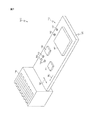
ここで図1を参照すると、伝熱管理装置100の1つの実施形態が示される。この実施形態において、伝熱管理装置100は、複合薄板120と、複合薄板120に結合された耐熱性の高い部品112と、複合薄板120に結合された耐熱性の低い部品114と、を有する回路基板組立体110である。ある実施形態において、複合薄板120は、プリント基板であってもよい。
Referring now to FIG. 1, one embodiment of a heat
本開示による実施形態は、複合薄板120に結合された複数の電気部品116を含んでもよい。伝熱管理装置100は、熱エネルギを周囲環境へと放出するように構成され、複合薄板120に結合されたヒートシンク118を有してもよい。
Embodiments in accordance with the present disclosure may include a plurality of
図1に示された実施形態において、耐熱性の高い部品112は、その動作に起因して発熱するパワーエレクトロニクスデバイスであってもよい。耐熱性の高い部品112は、例えばコンピュータ処理ユニット、グラフィカル処理ユニット及びチップセット等の集積回路を含む様々な電子デバイスであってもよい。ある実施形態において、耐熱性の高い部品112は、パワーインバータ、電圧整流器及び電圧調整器等において使用されるようなパワー半導体デバイスであってもよい。限定されるものではないが、例示的なパワー半導体デバイスは、パワー絶縁ゲートバイポーラトランジスタ及び金属酸化膜電界効果トランジスタ等を含む。別の実施形態において、耐熱性の高い部品112は、電気モーター又は発電器(generator)を含んでもよい。動作中、概して耐熱性の高い部品112は、耐熱性の高い部品112の設計された動作機能に起因する排熱として熱を生じる。電気部品は従来、温度過上昇の状態となった場合の温度誤動作又は温度による非一時的障害の影響を受けやすいため、伝熱管理装置において耐熱性の高い部品112によって生成された熱は、概して望ましいものではない。それにもかかわらず、耐熱性の高い部品112は、広い温度範囲に亘り動作し続ける。
In the embodiment shown in FIG. 1, the heat
更に、図1で示された実施形態において、耐熱性の低い部品114は、例えば平面的なカプラ、インダクタ/変圧器、Q値の高い共振回路、検出器、電流検知レジスタ、水晶発振器、配列された光学的部品又はヒューマンインタフェース制御ボタン等を含む様々な耐熱性の低い電子デバイスから選択され得る。耐熱性の低い部品114の動作は、耐熱性の高い部品112によって生成された熱エネルギによって悪い影響を受け得る。逆に、他の実施形態において、耐熱性の低い部品114は、例えば熱電発電器又は圧電ファン等の、上昇した熱エネルギで向上した効率で動作する耐熱性の低い電子デバイスであってもよい。更に別の実施形態において、耐熱性の低い部品114は、例えば多相ヒートパイプ及び対流ヒートシンク等の、上昇した温度で向上した効率で動作する熱機械デバイスであってもよい。こうした耐熱性の低い部品114へと流された上昇した熱エネルギは、耐熱性の低い部品114の性能を向上させ得る。従って、複合薄板120に結合された耐熱性の低い部品114の温度を管理するため、複合薄板120は、複合薄板120に沿って流れる熱流の方向及び/又は強度を変更する複数の伝熱管理機能を有する。
Further, in the embodiment shown in FIG. 1, the low
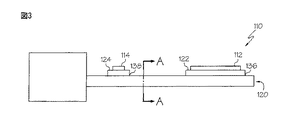
ここで図2から図4を参照すると、示された伝熱管理装置100の実施形態は、絶縁基板140と、絶縁基板140に少なくとも部分的に組み込まれた導熱体142と、絶縁基板140に少なくとも部分的に組み込まれた導電体144と、を備える複合薄板120を有する。複合薄板120は、少なくとも1つの電子部品取付モジュール122、124を更に有し、それぞれ複合薄板120に取付けられる。電子部品取付モジュール122、124は、耐熱性の高い部品112又は耐熱性の低い部品114のそれぞれと、複合薄板120に組み込まれた導電体144と、の間の電気接続部を提供する。複数の電子リードは、絶縁基板140を通って、電子部品取付モジュール122、124から従来知られているような、一連のビア内の(in a series of vias)導電体144へと延びる。電子部品取付モジュール122、124は、耐熱性の高い部品112又は耐熱性の低い部品114のそれぞれを、スナップインフィット又はロック保持カラー又はサーマルパッド(図示せず)によるアタッチメントによって固定してもよい。他の実施形態において、耐熱性の高い部品及び/又は耐熱性の低い部品112、114は、複合薄板120に結合されてもよく、且つ、例えば、はんだ又は溶接によって、導電体144と電気的導通状態で配置されてもよい。
2 through 4, the illustrated embodiment of the heat
図2から図4に示された実施形態において、複合薄板120は、絶縁基板140内に少なくとも部分的に組み込まれるように配置された導熱体142及び導電体144を含む。導熱体142は、例えば銅、銀、金及びこれらの合金を含む、高い熱伝導特性を有する任意の様々な材料から選択されてもよい。導熱体142は、絶縁基板の熱伝導率の係数kiよりも大きな熱伝導率の係数kcを有してもよく、kcが少なくともkiよりも大きな強度のオーダーであることを含んでもよい。同様に、導電体144は、例えば銅、銀、金及びこれらの合金等を含む、高い電子伝導特性を有する任意の様々な材料から選択されてもよい。絶縁基板140は、例えばカーボン強化材又はガラス強化材と結合され得るポリプロピレン、ポリエステル、ナイロン及びエポキシ等のようなプラスチックを含む、低い電子伝導性を有する任意の様々な材料から選択されてもよい。1つの実施形態において、絶縁基板140は、ガラス強化エポキシであるFR−4から作られてもよい。絶縁基板140は、熱伝導率の係数kiを有するが、これは、導熱体の熱伝導率の係数kcより小さい。
In the embodiment shown in FIGS. 2-4, the
図2から図4に示されたように、複合薄板120の実施形態は、絶縁基板140の一方の側部に沿って少なくとも部分的に組み込まれた導熱体142の内部接続された、より線(strand)の格子(lattice)を有するバルク領域132を含む。バルク領域132における導熱体142の格子は、概して耐熱性の高い部品112において生成された熱をヒートシンク118へと流す配向で配置される。示された実施形態において、格子は、導熱体142によって形成される複数の正方形のセルを有する。当然のことながら、様々な多角形形状、幅、深さ及び長さを有することを含むこうした格子の様々な構成は、本開示の範囲から逸脱することなく複合薄板120へと組み込まれ得る。示された実施形態において、導熱体142の格子は、耐熱性の高い部品112からヒートシンク118へと主方向(principal direction)90に延び、且つ、耐熱性の高い部品112からヒートシンク118へと主方向90に対して横断する交差方向92に延びるより線を含む。熱エネルギを交差方向92へと方向付けることによって、導熱体142の向上した比率は、熱エネルギをヒートシンク118へと方向付けるのに使用されてもよく、耐熱性の高い部品112からヒートシンク118及び周囲環境へと排出される熱の複合薄板120の効率を向上させ得る。
As shown in FIGS. 2-4, an embodiment of the
複合薄板120は、耐熱性の低い部品114近傍に配置された目的とする伝熱領域130を更に含む。目的とする伝熱領域130は、耐熱性の低い部品114を包囲する導熱体142の構成を有する。目的とする伝熱領域130の導熱体142は、バルク領域132の導熱体142と熱的導通状態であってもよく、これによって、熱流は、バルク領域132と目的とする伝熱領域130との間の導熱体142に沿って容易に流れる。導熱体142は、導電性も有するため、バルク領域132及び目的とする伝熱領域130の導熱体142間の熱的導通性は、バルク領域132及び目的とする伝熱領域130間の評価する(evaluating)電気的導通性によって変化し得る。これらの実施形態において、バルク領域132及び目的とする伝熱領域130は、熱流を、耐熱性の低い部品114から離れた方へと導いて(steer)もよい。目的とする伝熱領域130は、目的とする伝熱領域130近傍の位置において、複合薄板120の熱伝導率及び/又は熱容量を変化させる一方で、目的とする伝熱領域130から遠位に配置された位置において概して伝導性の伝熱(conductive heat transfer)を維持する。複合薄板120の熱伝導率を変更することによって、複合薄板120に沿った伝熱の安定状態が制御され得る。同様に、複合薄板120の熱容量を変更することによって、複合薄板120の、熱流の変化に対する一時的な(transient)熱的応答が制御され得る。
The composite
目的とする伝熱領域130、230、330の様々な実施形態は、図5から図7により詳細に示される。ここで示された目的とする伝熱領域130、230、330は、略円形であったが、当然のことながら、本開示に係る目的とする伝熱領域130、230、330の実施形態は、幾何学的形状によって限定されるべきものではない。従って、目的とする伝熱領域130、230、330の様々な実施形態は、様々な形状及び構成を呈してもよい。図5に示された実施形態において、目的とする伝熱領域130は、導熱体142及び絶縁基板140の複合構造によって形成される温度管理機能を有し、導熱体142は、耐熱性の低い部品の設置領域138を包囲する同心状のリング150で構成され、ここに、第2の電子部品取付モジュール124がある。目的とする伝熱領域130のリング150は、互いに交差しておらず、絶縁基板140によって互いに分離される。最も外側のリング150は、絶縁基板140に沿ってバルク領域132に配置された導熱体142の格子と熱的導通状態であってもよい。
Various embodiments of the targeted
目的とする伝熱領域130のリング150は、目的とする伝熱領域130を通して熱流を低減させつつ熱エネルギをリング150に沿って送る。従って、目的とする伝熱領域130は、耐熱性の低い部品114へと流れる熱エネルギの量を低減させ得る。こうして、目的とする伝熱領域130は、耐熱性の低い部品114を、複合薄板120に沿って流れ得る熱流から覆って(mask)もよい。目的とする伝熱領域130の使用(Incorporation)は、耐熱性の低い部品114が動作する温度に対してセンシティヴであり、且つ/又は温度の時間変化によって耐熱性の低い部品114の寸法を横断する用途において有用となり得る。目的とする伝熱領域130のリング150は、熱流の主方向90において目的とする伝熱領域130に亘り評価される温度降下を低減してもよい。温度降下の低減及び目的とする伝熱領域130に亘り方向付けられた関連する熱流の低減は、耐熱性の低い部品114の、耐熱性の高い部品112からの熱的絶縁性を提供する一方で、複合薄板120内における電気的導通性を維持する。
The
図5に示された目的とする伝熱領域130は、概して耐熱性の低い部品の設置領域138に亘り一定の温度を維持することによって、複合薄板120に等温領域を形成してもよい。従って、等温領域は、目的とする伝熱領域130内の温度変化の低減を示し、温度勾配にさらされるときに悪影響を受ける耐熱性の低い電気部品にとって有益となり得る。
The target
目的とする伝熱領域130、ここではリング150の温度管理機能は、目的とする伝熱領域130の有効熱伝導率(effective thermal conductivity)がバルク領域132の有効熱伝導率と同等となるように選択され得る。これは、低減された目的とする伝熱領域130及びバルク領域132の熱伝導率の係数の平均の比較によって評価されてもよく(すなわち、kb=f・kc+(1−f)・ks)、ここで、kbは、低減されたバルク領域132の熱伝導率の係数の平均であり、kcは、導熱体142の熱伝導率の係数であり、ksは、絶縁基板140の熱伝導率の係数であり、fは、バルク領域132内の導熱体142の体積分率(volume fraction)である。更に、ある実施形態において、リング150の幅及び深さは、目的とする伝熱領域130の熱容量を変化させるため、互いに対して変化し、且つ/又は、それらの長さに沿って変化してもよい。ある実施形態において、目的とする伝熱領域130の有効熱伝導率は、バルク領域132の有効熱伝導率の約10%の範囲内にある。他の実施形態において、目的とする伝熱領域130の有効熱伝導率は、バルク領域132の有効熱伝導率の約5%の範囲内にある。更に別の実施形態において、目的とする伝熱領域130の有効熱伝導率は、バルク領域132の有効熱伝導率に略等しい。目的とする伝熱領域130とバルク領域132との間の有効熱伝導率間の差の最小化は、目的とする伝熱領域130から離された位置における熱流の中断(disruption)を低減する。
The temperature management function of the target
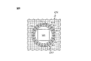
ここで図6を参照すると、目的とする伝熱領域230の別の実施形態が示される。目的とする伝熱領域230は、導熱体142及び絶縁基板140の複合構造を有し、導熱体142は、耐熱性の低い部品の設置領域138、ここでは、第2の電子部品取付モジュール124、を包囲するリング150と、複数のスポーク152であって同心円状のリング150を互いに熱的導通状態となるように配置するために同心円状のリング150間で径方向に延びる複数のスポーク152と、で構成される。図6に示されたスポーク152は径方向の配向で配置されるが、当然のことながら、スポーク152は、用途の要求に基づいた様々な構成で配置されてもよい。最も外側のリング150は、絶縁基板140に沿って配置された導熱体142の格子と熱的導通状態であってもよい。
Referring now to FIG. 6, another embodiment of the intended
目的とする伝熱領域230の同心円状のリング150及びスポーク152は、熱流を、スポーク152に沿って、リング150間で流し、それによって、目的とする伝熱領域230を通る熱流は、格子のような構成に導熱体142及び絶縁基板140を組み込む複合薄板120のバルク領域132と比較して増加する。この実施形態において、格子のような構成の導熱体142が複合薄板120の耐熱性の高い部品の設置領域136の周りに配置される一方で、目的とする伝熱領域230は、耐熱性の低い部品の設置領域138を包囲する。従って、目的とする伝熱領域230は、耐熱性の低い部品114へと流れる熱流を増加させ得る。こうして、目的とする伝熱領域230は、耐熱性の低い部品114へと熱エネルギを集中させる。目的とする伝熱領域230の使用は、例えば熱電部品を備え、上昇した温度勾配において向上した効率で耐熱性の低い部品114が動作する用途において有益となり得る。目的とする伝熱領域230の同心円状のリング150間のスポーク152は、熱流の主方向90において目的とする伝熱領域230に亘り評価される温度降下を増し得る。温度降下の増加及び目的とする伝熱領域230に亘り流れる熱流の同様な増加は、複合薄板120内の電気的導通が維持される一方で、耐熱性の高い部品112によって生成された熱から、耐熱性の低い部品114の熱量増幅を生じさせ得る。
The
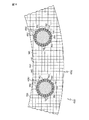
ここで図7を参照すると、目的とする伝熱領域330の更に別の実施形態が示される。目的とする伝熱領域330は、導熱体142及び絶縁基板140の複合薄板を有し、導熱体142は、耐熱性の低い部品の設置領域138、ここでは第2の電子部品取付モジュール124を包囲するために螺旋状の配向で延びる複数のスポーク154で構成される。図7で示されたスポーク154は、スポーク154の半径が格子のような領域からの距離の増加につれて減じられる螺旋状の配向で構成される一方で、当然のことながら、スポーク154は、用途の要求によって様々な構成で構成されてもよい。
Referring now to FIG. 7, yet another embodiment of the intended
目的とする伝熱領域330のスポーク154は、スポーク154に沿って且つ目的とする伝熱領域330を通る線形方向の移動(travelling)から離れるように熱エネルギを送り、それによって、目的とする伝熱領域330に案内された熱エネルギは、スポーク154の方向に従って回転させられる。こうして、目的とする伝熱領域330は、熱エネルギを耐熱性の低い部品114の周りに方向付けてもよく、これによって、目的とする伝熱領域330内の熱エネルギの輸送方向を回転させる。ある実施形態において、目的とする伝熱領域330は、耐熱性の低い部品の設置領域138近傍の、目的とする伝熱領域330の内部に沿って評価された温度降下が目的とする伝熱領域330の外部に沿って評価された温度降下とは逆となるように(inverted)熱流を回転させてもよい。目的とする伝熱領域330の使用は、熱が特定の方向に流れるときに、耐熱性の低い部品114が向上した効率で動作する用途において有益となり得る。温度降下及び目的とする伝熱領域330に亘り流れる同様な熱流の減少は、耐熱性の低い部品114の、耐熱性の高い部品112によって生成された熱からの熱的絶縁性を提供し得る一方で、複合薄板120内の電気的導通を維持する。
The
本開示に係る目的とする伝熱領域130、230、330の、複合薄板120における使用は、複合薄板120の表面に沿った伝導性の伝熱の変化を可能とする。上述したように、回路基板組立体の実施形態が、上昇した温度又は高い温度勾配にさらされるときに悪影響を被る電気部品を有するとき、電気部品を熱流から覆い(shield)、又は、部品に対する熱エネルギの流入を低減するために熱流を回転させる、目的とする伝熱領域が望まれる。これらの実施形態において、目的とする伝熱領域の使用は、耐熱性の低い部品が電気的導通のため複合薄板へと取り付けられることを可能とする一方で、耐熱性の低い電気部品における上昇した温度のいかなる影響も最小化する。更に、上述したように、目的とする伝熱領域は、熱的環境を形状化するため(to provide shape the thermal environment)、耐熱性の低い部品を包囲する複合薄板に沿った別の幾何学的形状で構成されてもよい。
Use of the intended
同様に、上昇した温度において向上した効率で動作する電気部品のため、回路基板組立体の実施形態は、電気部品へと熱流を集める目的とする伝熱領域を組み込んでもよく、これによって、電気部品周りの温度を上昇させる。これらの実施形態において、温度の上昇は、耐熱性の低い電子部品の性能を向上させ得る。従って、熱エネルギを耐熱性の低い電子部品に集めることによって、耐熱性の低い電子部品の向上した性能が実現され得る。 Similarly, for electrical components that operate with increased efficiency at elevated temperatures, circuit board assembly embodiments may incorporate a heat transfer area intended to collect heat flow into the electrical components, thereby providing electrical components. Increase the ambient temperature. In these embodiments, an increase in temperature can improve the performance of electronic components with low heat resistance. Therefore, by collecting thermal energy in electronic components with low heat resistance, improved performance of electronic components with low heat resistance can be realized.
再度図2から図4を参照すると、当然のことながら、導電体144及び絶縁基板140は、導熱体142によって伝えられる熱エネルギに加えて、耐熱性の高い部品112からヒートシンク118及び/又は耐熱性の低い部品114へと熱エネルギを伝えてもよい。しかしながら、導熱体142は、絶縁基板140及び導電体144の熱伝導率より大きな、(導熱体142の熱伝導率及び幅及び厚さに基づいた)熱伝導率を示してもよい。導熱体142の熱伝導率は、絶縁基板140及び導電体144より大きいため、耐熱性の高い部品112によって放出された熱エネルギの大部分(substantial portion)が導熱体142によって送られ得る。本開示に係る複合薄板120の詳細な設計は、導熱体142の位置が決定されたときに絶縁基板140及び導電体144の配置、寸法及び熱伝導率を決定し得る(may account for)。従って、複合薄板120の設計は、回路基板組立体110の様々な電気部品の熱分散(thermal dissipation)及び電気的導通要求の両方を決定し得る。
Referring again to FIGS. 2-4, it will be appreciated that the
ある実施形態において、導熱体は、複合薄板においていかなる付加的な導電体も必要とせず耐熱性の高い部品を耐熱性の低い部品と電気的導通状態で配置してもよい。これらの実施形態において、導熱体は、例えば耐熱性の低い部品及び耐熱性の高い部品を含む、複合薄板に取付けられた部品間の電気導通状態を同時に維持する一方で、熱流の流れを複合薄板に沿って送るように構成される。従って、こうした実施形態において、導熱体は、熱エネルギ及び電気エネルギの両方を導通させる。 In certain embodiments, the heat conductor may not require any additional conductors in the composite sheet and may place the high heat resistant component in electrical communication with the low heat resistant component. In these embodiments, the heat conductor simultaneously maintains electrical continuity between components mounted on the composite sheet, including, for example, low heat resistant parts and high heat resistant parts, while the flow of heat flow is reduced to the composite sheet. Configured to send along. Thus, in such embodiments, the heat conductor conducts both thermal and electrical energy.
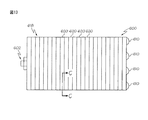
ここで図8から図10を参照すると、伝熱管理装置400の別の実施形態が示される。この実施形態において、伝熱管理装置400は、複数の薄板422、424を備える複合積層板組立体420を有する。図8から図10に示された実施形態において、複合積層板組立体420は、第1の薄板422及び第2の薄板424を有する。当然のことながら、本開示に係る複合積層板組立体420は、特定の用途の要求に基づいて任意の数の薄板を有してもよい。第1の薄板422は、耐熱性の高い部品112及び耐熱性の低い部品114がそれぞれ結合され得る、第1の電子部品取付モジュール122及び第2の電子部品取付モジュール124を有する。複合積層板組立体420の第1の薄板422は、絶縁基板140に少なくとも部分的に組み込まれた複数の導電体144を有してもよい。示された実施形態において、導電体144は、第1の電子部品取付モジュール122及び第2の電子部品取付モジュール124に対向する第1の薄板422の内面に沿って配置される。電子部品取付モジュール122、124は、導電体144と電気的導通状態で維持される。示された実施形態において、複数の電子リード444は、第1の電子部品取付モジュール122及び第2の電子部品取付モジュール124から導電体144へと延び、第1の電子部品取付モジュール122及び第2の電子部品取付モジュール124を、導電体144と電気的導通状態で配置する。
With reference now to FIGS. 8-10, another embodiment of a heat
第1の薄板422は、組み込まれた導熱体442も有する。組み込まれた導熱体442は、絶縁基板140内に少なくとも部分的に組み込まれ、導電体144から電気的に絶縁される。図8から図10に示された実施形態において、組み込まれた導熱体442は、第1の薄板422であってこれに沿って第1の電子部品取付モジュール122及び第2の電子部品取付モジュール124が配置される第1の薄板422の、外面から離される。組み込まれた導熱体442は、第1の電子部品取付モジュール122及び第2の電子部品取付モジュール124に対向する第1の薄板422の内面に沿って配置される(exposed)。
The first
第2の薄板424は、絶縁基板440に少なくとも部分的に組み込まれた絶縁基板440及び導熱体142を有する。図8から図10に示された実施形態において、導熱体142は、第2の薄板424の上面に沿って配置される。導熱体142は、上述した図2から図4で説明したのと同様な格子内に配置されることを含む様々な構成で配置されてもよい。導熱体142は、導熱体142及び導電体144が互いに電気的に絶縁されたままであるように、導電体144から離されるように配置される。導熱体142は、第1の薄板422の組み込まれた導熱体442と熱的導通状態で配置される。
The second
第2の薄板424は、第2の薄板424の絶縁基板440内に少なくとも部分的に組み込まれた、目的とする伝熱領域130を更に含む。上述した目的とする伝熱領域130の実施形態と同様、目的とする伝熱領域130は、複合積層板組立体420に沿って送られる熱流を形状化(shape)するため、複合積層板組立体420の近位の(local)熱伝導率を変更してもよい。目的とする伝熱領域130の実施形態は、耐熱性の高い部品112によって生成された熱エネルギから耐熱性の低い部品114を保護してもよく(shield)、或いは、耐熱性の高い部品112から耐熱性の低い部品114へと熱エネルギを集めてもよい。
The second
電気信号は、耐熱性の高い部品112から或いは耐熱性の高い部品112へと、導電体144を通して伝えられる。耐熱性の高い部品112によって生成された熱は、複合積層板組立体420の第1の薄板422へと送られる。耐熱性の高い部品112によって生成された熱エネルギの大部分は、第1の薄板422の組み込まれた導熱体442へと送られる。熱エネルギは、複合積層板組立体420に沿って組み込まれた導熱体442から第2の薄板424の導熱体142へと、ヒートシンク118及び/又は耐熱性の低い部品114へと向かう熱的経路に沿って送られる。耐熱性の高い部品112からの熱エネルギは、目的とする伝熱領域130の構成に基づいて、選択的に耐熱性の低い部品114からシールドされ、耐熱性の低い部品114へと集められ、或いは、耐熱性の低い部品114に関連して案内される。
The electric signal is transmitted through the
当然のことながら、複数の薄板の複合積層板組立体420の様々な構成は、複合積層板組立体420に沿った熱流の輸送が、複合積層板組立体420に取付けられた電気部品間の電気的導通を維持する一方で、目的の効果を提供するべく制御され得るように、互いに電気的に絶縁された導熱体142及び導電体144を組み込んでもよい。電気部品、導熱体及び/又は導電体を絶縁基板440へと組み込む付加的な薄板は、目的の電子的組立体が、要求に応じて、熱エネルギを周囲環境へと放熱でき、シールドし、或いは、耐熱性の低い部品電子部品へと集めることができるように回路基板組立体410に含まれてもよい。従って、当然のことながら、本開示に係る複合積層板組立体420の実施形態は、回路基板組立体410の電気部品の熱分散を生じさせ、且つ電気的導通要求を満たすように設計されてもよい。更に、複合積層板組立体420の導熱体142及び導電体144は、熱流が、導電体144の熱伝導の影響を最小化する導熱体142に沿って選択的に送られ得るように絶縁基板440によって互いに分離されてもよい。
It will be appreciated that the various configurations of the multi-lamellar
複数の薄板の複合積層板組立体の更に別の実施形態において、特定の層の導熱体は、熱的導通及び電気的導通の両方を伝熱管理装置の部品に提供してもよい。ある実施形態において、伝熱管理装置の部品間の電気的導通は、部品が取付けられたプリント基板から離された複合薄板へと方向付けられてもよい。こした実施形態において、部品間の熱的導通及び電気的導通は、複数の薄板の複合積層板組立体の別の層を通して維持されてもよい。 In yet another embodiment of a multi-lamellar composite laminate assembly, a particular layer of heat conductor may provide both thermal conduction and electrical conduction to a component of the heat transfer management device. In certain embodiments, electrical continuity between components of the heat transfer management device may be directed to a composite sheet separated from the printed circuit board on which the components are attached. In such embodiments, thermal and electrical continuity between components may be maintained through separate layers of a multi-lamellar composite laminate assembly.
ここで図11を参照すると、複合積層板組立体510を組み込む伝熱管理装置500の別の実施形態が示される。この実施形態において、複合積層板組立体510は、複数の電子部品取付モジュール122を備え、且つ、少なくとも1つの、第2の電子部品取付モジュール124を備える複合薄板520を有する。耐熱性の高い部品112は、電子部品取付モジュール122及び耐熱性の低い部品114へとそれぞれ取り付けられ、耐熱性の低い電子部品は、第2の電子部品取付モジュール124に結合される。上述した実施形態と同様、複合薄板520は、絶縁基板540へと少なくとも部分的に組み込まれた導熱体542も有する。導熱体542は、その要素に沿って熱を伝えるように構成される。図11に示された実施形態において、導熱体542は、互いに熱的導通状態にある複数のより線を有する格子内に構成される。更に導熱体12は、目的とする伝熱領域530に構成される。目的とする伝熱領域530は、導熱体142のバルク領域532と比較して変形されたパターンを有し、それによって、バルク領域532における熱流の方向は、目的とする伝熱領域530における方向とは異なる。
Referring now to FIG. 11, another embodiment of a heat
図11に示された実施形態において、目的とする伝熱領域530は、熱エネルギを、それぞれの耐熱性の高い部品112から、耐熱性の低い部品114へと送り、熱エネルギを耐熱性の高い部品112から耐熱性の低い部品114へと集める。こうした構成は、耐熱性の低い部品114が上昇した温度において向上した効率で動作する耐熱性の低い電子部品である用途に好適である。耐熱性の高い部品112、耐熱性の低い部品114、及び目的とする伝熱領域530の構成は、耐熱性の低い部品114へと流れる熱流を増加させ得る。
In the embodiment shown in FIG. 11, the target
ここで図12から図14を参照すると、伝熱管理装置600の別の実施形態が示される。この実施形態において、伝熱管理装置600は、複合積層板組立体618を形成するために互いに結合された複数の複合薄板620を有する。複合薄板620は、電気モーター602の周りで組み立てられる。電気モーター602は、回転子の原動力を生成する固定子604内で回転するように構成された回転子606を有する。示された実施形態において、原動力の強さは、固定子604のコイル(図示せず)を流れる電気量、及び、回転子606の磁力の強さに基づく。コイルを流れる電気量が増加すると、概して回転子606によって提供される原動力が増加する。
Referring now to FIGS. 12-14, another embodiment of a heat
しかしながら、コイルを流れる電気の増加は、概して電気モーター602の動作温度の増加に関連する。電気モーター602の固定子604の温度を管理するため、伝熱管理装置600は、固定子604から熱流を引き出す複数の除熱装置610を有してもよく、これによって、固定子604の温度を低下させる。除熱装置610は、上昇した温度及び/又は上昇した温度勾配において向上した効率で駆動することができ、このため、除熱装置610は、耐熱性の低い部品である。ある実施形態において、除熱装置610は、例えば、非限定的に、ヒートパイプ、熱電クーラー及び伝導性ヒートシンク等であってもよい。
However, the increase in electricity flowing through the coil is generally associated with an increase in the operating temperature of the
ここで図14を参照すると、複合薄板620の1つが示される。複合積層板組立体618(図13に示される)におけるそれぞれの複合薄板620は、導熱体142及び絶縁基板140の同等な層を有してもよい。図14に示された実施形態において、複合薄板620は、絶縁基板140に少なくとも部分的に組み込まれた導熱体142を有する。導熱体142は、バルク領域632及び複数の目的とする伝熱領域630に構成され、バルク領域632の伝導性の伝熱係数は、目的とする伝熱領域630の伝導性の伝熱係数より低い。図14に示された実施形態において、目的とする伝熱領域630は、互いに同心の関係で構成された複数のリング150と、径方向の関係に構成され且つ複数のリング150を互いに相互連結する複数のスポーク152と、を有する。上述したように、目的とする伝熱領域630は、熱流を除熱装置610へと送るために、耐熱性の高い部品(ここでは固定子604)から熱流を集めようとする。目的とする伝熱領域630のそれぞれを横断する熱流を増加させることによって、固定子604から排出される熱エネルギは、高い効率で除熱装置610へと送られ得る。排熱の効率の増加は、設計包絡線(design envelope)を横断する固定子604の温度を維持するのに必要とされる除熱装置610の数を減らすことができる。更に、この実施形態において、複合薄板620のバルク領域632及び目的とする伝熱領域360は、熱流を除熱装置610(すなわち耐熱性の低い部品)へと導いてもよい。従って、目的とする伝熱領域630の使用は、伝熱管理装置600のコスト及び複雑さを低減し得る。
Referring now to FIG. 14, one of the
当然のことながら、本開示に係る伝熱管理装置は、少なくとも、基板において少なくとも部分的に組み込まれた絶縁基板及び導熱体を備える複合薄板を有してもよい。導熱体は、目的とする伝熱領域及びバルク領域において構成される。プリント回路基板の熱伝導率は、複合薄板に沿った熱流の流れが目的とする伝熱領域においてバルク領域と比較して変化するように、導熱体によって局所的に変化する。目的とする伝熱領域における熱エネルギの流れの変化は、耐熱性の低い部品が複合薄板に配置され、且つ、バルク領域に配置される耐熱性の低い部品と比較して、向上した効率で動作することを可能とする。 Of course, the heat transfer management device according to the present disclosure may include at least a composite thin plate including an insulating substrate and a heat conductor at least partially incorporated in the substrate. A heat conductor is comprised in the target heat-transfer area | region and a bulk area | region. The thermal conductivity of the printed circuit board is locally changed by the heat conductor so that the flow of heat flow along the composite sheet changes in the intended heat transfer area compared to the bulk area. The change in the flow of thermal energy in the target heat transfer area is due to the fact that parts with low heat resistance are placed on a composite sheet and operate with improved efficiency compared to parts with low heat resistance placed in the bulk area. It is possible to do.
4つのサンプルが上述した目的とする伝熱領域によって提案された伝熱特性を評価する試験のため準備された。標準の試験片(coupons)は、0.69W/(m・K)の熱伝導率の係数を有する絶縁基板としてRO4350B材を用いて作られる。試験片は、115mmの全長と、50mmの幅を有する。絶縁基板は、508μmの厚さを有する。400W/(m・K)の熱伝導率の係数を有する銀めっきされた銅は、化学的エッチングによって、絶縁基板の上面及び底面に沿った35μmの厚さでバルク領域へと形成され、プリント回路基板試験片の全体厚さを578μmとする。銀めっきされた銅は、2.5mmの長さ及び幅寸法を有した複数の正方形のセルを備える200μmの厚さを有してバルク領域において構成された。絶縁基板の両端から37.5mm延びる完全に銀めっきされた銅の熱的ブスバー(thermal bus bars)は、内部流れ及び外部流れの熱を目的の領域、試験片の中心における40mmの所へと提供するためにも組み込まれる。正確な熱画像を容易とするため、高い放射率(emissivity)(ε=0.96〜0.98)の薄い一様なコーティング、平面的な黒いペイント、クライロン1618が、それぞれの試験片の目的の領域に塗布された。それぞれの複合構造の露出された上側の熱的輪郭は、試験装置の上方に直接配置された、校正されたIRカメラ(FLIR SC7650)によって得られる。10mmの径を有する同心円状のリングの内径に対応して横断する温度勾配が計測される。 Four samples were prepared for testing to evaluate the heat transfer characteristics proposed by the target heat transfer region described above. Standard coupons are made using RO4350B material as an insulating substrate with a coefficient of thermal conductivity of 0.69 W / (m · K). The test piece has a total length of 115 mm and a width of 50 mm. The insulating substrate has a thickness of 508 μm. Silver-plated copper having a coefficient of thermal conductivity of 400 W / (m · K) is formed into a bulk region with a thickness of 35 μm along the top and bottom surfaces of the insulating substrate by chemical etching, and printed circuit The total thickness of the substrate test piece is 578 μm. Silver plated copper was constructed in the bulk region with a thickness of 200 μm with a plurality of square cells with 2.5 mm length and width dimensions. Fully silvered copper thermal bus bars extending 37.5mm from both ends of the insulating substrate provide internal and external flow heat to the target area, 40mm in the center of the specimen It is also incorporated to do. To facilitate accurate thermal imaging, a thin uniform coating with high emissivity (ε = 0.96-0.98), planar black paint, Crylon 1618 is the purpose of each specimen. Applied to the area. The exposed upper thermal profile of each composite structure is obtained by a calibrated IR camera (FLIR SC7650) placed directly above the test apparatus. A transverse temperature gradient is measured corresponding to the inner diameter of a concentric ring having a diameter of 10 mm.
最大動力50Wを有する1つの120Vのカートリッジヒーターを受け入れるように縦に機械加工された中心孔を有する30mm×30mm×50mmの銅製のブロックヒーターでそれぞれの試験片に動力が付与される。11Wの最大冷却動力を有する直空(direct-to-air)熱電クーラーは、ヒーターに対向して配置され、ヒートシンクとして使用される。試験装置は、目的の領域以外絶縁部によって覆われ、大気環境に露出される。 Each specimen is powered with a 30 mm × 30 mm × 50 mm copper block heater with a central hole machined vertically to accept one 120V cartridge heater with a maximum power of 50W. A direct-to-air thermoelectric cooler with a maximum cooling power of 11 W is placed opposite the heater and used as a heat sink. The test apparatus is covered with an insulating portion other than the target area and exposed to the atmospheric environment.
コンピュータシミュレーションモデルは、それぞれのテストケースの安定状態の伝熱をシミュレーションするように構成される。 The computer simulation model is configured to simulate the steady state heat transfer of each test case.
ベースライン。ベースライン試験片は、バルク領域が目的の領域に沿って延びる複数の正方形セルを有するように目的とする伝熱領域なく準備される。 Base line. The baseline specimen is prepared without a target heat transfer region such that the bulk region has a plurality of square cells extending along the target region.
目的の領域を横断する35Kの温度差を形成するため、動力をベースライン試験片に付与すると、他の試験片の同心円状のリングの内径に相当する距離で評価された温度勾配は、∇T≒8.3K/cmで評価される。比較において、シミュレーションモデルは、温度勾配が∇T≒9K/cmであることを示した。 When power is applied to the baseline specimen to create a 35K temperature difference across the region of interest, the temperature gradient evaluated at a distance corresponding to the inner diameter of the concentric ring of the other specimen is ∇T Approximately 8.3 K / cm. In comparison, the simulation model showed that the temperature gradient was ∇T≈9 K / cm.
サンプル1。複数の同心円状のリングを備えた図5に対応する、目的とする伝熱領域を有する試験片は、9つの250μm幅の同心の銅リングを有して生成され、それぞれのリングは、均一に互いに離して配置され、同心円状のリングの外径は、18.5mmとなり、内径は10mmとなった。 Sample 1. A specimen with the desired heat transfer area, corresponding to FIG. 5 with a plurality of concentric rings, was produced with nine 250 μm wide concentric copper rings, each ring being uniformly The outer diameter of the concentric rings arranged apart from each other was 18.5 mm, and the inner diameter was 10 mm.
目的の領域を横断する35Kの温度差を形成するために動力をベースライン試験片に付与すると、同心円状のリングの内径を横断する、評価された温度勾配は、∇≒0.22K/cmと評価された。比較において、シミュレーションモデルは、温度勾配が∇T≒0.86K/cmであることを示した。 When power is applied to the baseline specimen to create a 35 K temperature difference across the region of interest, the estimated temperature gradient across the inner diameter of the concentric ring is ∇≈0.22 K / cm. It was evaluated. In comparison, the simulation model showed that the temperature gradient was ∇T≈0.86 K / cm.
サンプル2。目的とする伝熱領域を有する試験片は、同心円状のリングを相互に連結する径方向のスポークを備えて複数の同心円状のリングを有する図6に対応し、2つの250μm幅の同心の銅リング、18.5mmの外径を有する外部のリング、及び、10mmの内径を有する内部のリングが形成される。サンプルは、同心円状のリング周りに一様に配列され且つ外部リング及び内部リングを接続する90の径方向スポークを有する。 Sample 2. The specimen having the intended heat transfer region corresponds to FIG. 6 with a plurality of concentric rings with radial spokes interconnecting the concentric rings, and two 250 μm wide concentric copper. A ring, an outer ring having an outer diameter of 18.5 mm, and an inner ring having an inner diameter of 10 mm are formed. The sample has 90 radial spokes uniformly arranged around the concentric rings and connecting the outer and inner rings.
目的の領域を横断する35Kの温度差を形成するために動力をベースライン試験片へと付与すると、同心円状のリングの内径を横断して評価される温度勾配は、∇T≒16.7K/cmと評価された。比較において、シミュレーションモデルは、温度勾配が∇T≒19.5K/cmであることを示した。 When power is applied to the baseline specimen to create a 35 K temperature difference across the region of interest, the temperature gradient evaluated across the inner diameter of the concentric ring is ∇T≈16.7 K / cm. In comparison, the simulation model showed that the temperature gradient was ∇T≈19.5 K / cm.
サンプル3。複数のスポークを備えた、図7に相当する目的とする伝熱領域を有する試験片は、25mmの外径を有し、且つ、10mmの内径を有して形成された。サンプルは、16の同等に配置された対数螺旋状の(logarithmic spiral)銅スポークを有し、内径周りで略300°覆われる。それぞれの螺旋状スポークは、テーパー状であり、177μmの内径幅及び414μmの外径幅を有する。 Sample 3. A test piece having a target heat transfer region corresponding to FIG. 7 and having a plurality of spokes was formed with an outer diameter of 25 mm and an inner diameter of 10 mm. The sample has 16 equally arranged logarithmic spiral copper spokes, covered approximately 300 ° around the inner diameter. Each helical spoke is tapered and has an inner diameter width of 177 μm and an outer diameter width of 414 μm.
目的の領域を横断する35Kの温度差を形成するためにベースライン試験片に動力付与すると、同心円状のリングの内径を横断して評価された温度勾配は、∇T≒1.1K/cmと評価し、温度勾配は、負であり、熱流が目的とする伝熱領域を横断して逆に流れることを示し、熱流は効果的に回転されることを示した。比較において、シミュレーションモデルは、負の温度勾配が∇T≒1.9K/cmとなることを示した。 When powering the baseline specimen to form a 35K temperature difference across the region of interest, the temperature gradient evaluated across the inner diameter of the concentric ring is ∇T≈1.1 K / cm. Evaluated, the temperature gradient was negative, indicating that the heat flow flows back across the intended heat transfer region, indicating that the heat flow is effectively rotated. In comparison, the simulation model showed that the negative temperature gradient was ∇T≈1.9 K / cm.
任意の定量比較、値、計測値又は他の代表値に元々備わり得る不確かさの本来の程度(inherent degree)を示すために「概して」という語がここで使用されてきたことに留意されたい。ここで、この語は、本主題の基本的機能の変更なく、言及された参照から定量的代表値が変化し得る程度を示すためにも使用される。 Note that the term “generally” has been used herein to indicate the inherent degree of uncertainty that may inherently be present in any quantitative comparison, value, measurement, or other representative value. Here, the term is also used to indicate the extent to which the quantitative representative value can vary from the referenced reference without changing the basic function of the subject matter.
特定の実施形態がここで示され且つ説明されてきたが、当然のことながら、特許請求された主題の精神及び範囲から逸脱することなく、様々な他の変形例及び変更がなされ得る。更に、請求された主題の様々な態様がここで説明されてきたが、こうした態様は、組合せて使用される必要はない。従って、添付の請求の範囲は、特許請求の範囲内の主題のこうした全ての変形例及び変更を包含する。 While particular embodiments have been shown and described herein, it will be appreciated that various other modifications and changes can be made without departing from the spirit and scope of the claimed subject matter. Moreover, although various aspects of the claimed subject matter have been described herein, these aspects need not be used in combination. Accordingly, the appended claims encompass all such variations and modifications of the subject matter as claimed.
90 主方向
92 交差方向
100 伝熱管理装置
110 回路基板組立体
112 耐熱性の高い部品
114 耐熱性の低い部品
116 電気部品
118 ヒートシンク
120 複合薄板
122 電子部品取付モジュール
124 電子部品取付モジュール
130 目的とする伝熱領域
132 バルク領域
136 耐熱性の高い部品の設置領域
138 耐熱性の低い部品の設置領域
140 絶縁基板
142 導熱体
144 導電体
150 リング
152 スポーク
154 スポーク
230 目的とする伝熱領域
330 目的とする伝熱領域
400 伝熱管理装置
410 回路基板組立体
420 複合積層板組立体
422 第1の薄板
424 第2の薄板
440 絶縁基板
442 導熱性
444 電子リード
500 伝熱管理装置
510 複合積層板組立体
520 複合薄板
532 バルク領域
600 伝熱管理装置
602 電気モーター
604 固定子
606 回転子
610 除熱装置
618 複合積層板組立体
620 複合薄板
630 目的とする伝熱領域
632 バルク領域
90 Main direction 92
Claims (20)
絶縁基板及び該絶縁基板に少なくとも部分的に組み込まれた導熱体を有する複合薄板と、
該複合薄板に結合された耐熱性の低い部品と、
前記複合薄板に結合され且つ前記耐熱性の低い部品から遠位に配置された耐熱性の高い部品であって動作中に発熱する耐熱性の高い部品と、を具備する伝熱管理装置であって、
前記導熱体及び前記絶縁基板が、前記耐熱性の低い部品近傍にある目的とする伝熱領域内及び前記耐熱性の高い部品近傍にあるバルク領域内に構成され、且つ、前記目的とする伝熱領域及び前記バルク領域が、互いに熱的導通状態にある伝熱管理装置。 A heat transfer management device,
A composite thin plate having an insulating substrate and a heat conductor at least partially incorporated in the insulating substrate;
A low heat-resistant component bonded to the composite sheet;
A heat-resistant management device comprising: a high-heat-resistant component coupled to the composite thin plate and disposed distally from the low-heat-resistant component; and a high-heat-resistant component that generates heat during operation. ,
The heat conductor and the insulating substrate are configured in a target heat transfer region in the vicinity of the low heat-resistant component and in a bulk region in the vicinity of the high heat-resistant component, and the target heat transfer A heat transfer management device in which the region and the bulk region are in thermal conduction with each other.
絶縁基板と、
前記絶縁基板に少なくとも部分的に組み込まれた導熱体と、
耐熱性の低い部品の設置領域と、耐熱性の高い部品の設置領域と、を具備する複合薄板であって、
前記導熱体及び前記絶縁基板が、前記耐熱性の低い部品の設置領域近傍にある目的とする伝熱領域及び前記耐熱性の高い部品の設置領域近傍にあるバルク領域に配置され、且つ、前記目的とする伝熱領域及び前記バルク領域が、互いに熱的導通状態にある複合薄板。 A composite sheet for directing heat transfer,
An insulating substrate;
A heat conductor at least partially incorporated in the insulating substrate;
A composite thin plate having an installation area for parts having low heat resistance and an installation area for parts having high heat resistance,
The heat conducting body and the insulating substrate are disposed in a target heat transfer area in the vicinity of the installation area of the low heat resistant component and a bulk area in the vicinity of the installation area of the high heat resistant component, and the object A composite thin plate in which the heat transfer region and the bulk region are in thermal conduction with each other.
Applications Claiming Priority (4)
| Application Number | Priority Date | Filing Date | Title |
|---|---|---|---|
| US201361816917P | 2013-04-29 | 2013-04-29 | |
| US61/816,917 | 2013-04-29 | ||
| US14/038,837 | 2013-09-27 | ||
| US14/038,837 US20140318758A1 (en) | 2013-04-29 | 2013-09-27 | Composite laminae having thermal management features and thermal management apparatuses comprising the same |
Publications (2)
| Publication Number | Publication Date |
|---|---|
| JP2014216655A true JP2014216655A (en) | 2014-11-17 |
| JP2014216655A5 JP2014216655A5 (en) | 2017-06-15 |
Family
ID=51788257
Family Applications (2)
| Application Number | Title | Priority Date | Filing Date |
|---|---|---|---|
| JP2014092535A Pending JP2014216655A (en) | 2013-04-29 | 2014-04-28 | Heat transfer management apparatus and composite lamina |
| JP2014092593A Active JP6306418B2 (en) | 2013-04-29 | 2014-04-28 | Printed circuit board, circuit board assembly, and heat transfer management device |
Family Applications After (1)
| Application Number | Title | Priority Date | Filing Date |
|---|---|---|---|
| JP2014092593A Active JP6306418B2 (en) | 2013-04-29 | 2014-04-28 | Printed circuit board, circuit board assembly, and heat transfer management device |
Country Status (2)
| Country | Link |
|---|---|
| US (2) | US9433074B2 (en) |
| JP (2) | JP2014216655A (en) |
Families Citing this family (11)
| Publication number | Priority date | Publication date | Assignee | Title |
|---|---|---|---|---|
| US9511549B2 (en) * | 2014-06-02 | 2016-12-06 | Toyota Motor Engineering & Manufacturing North America, Inc. | Anisotropic thermal energy guiding shells and methods for fabricating thermal energy guiding shells |
| US9779199B2 (en) * | 2014-07-25 | 2017-10-03 | Toyota Motor Engineering & Manufacturing North America, Inc. | Circuit boards with thermal control and methods for their design |
| US9699883B2 (en) * | 2015-01-08 | 2017-07-04 | Toyota Motor Engineering & Manufacturing North America, Inc. | Thermal switches for active heat flux alteration |
| US10316852B2 (en) * | 2015-05-11 | 2019-06-11 | Hanon Systems | Air conditioner for vehicle |
| US10193047B2 (en) | 2015-08-14 | 2019-01-29 | Toyota Motor Engineering & Manufacturing North America, Inc. | Electronic assemblies incorporating heat flux routing structures for thermoelectric generation |
| US9990457B2 (en) | 2016-01-12 | 2018-06-05 | Toyota Motor Engineering & Manufacturing North America, Inc. | Switching circuit including wire traces to reduce the magnitude of voltage and current oscillations |
| US10206310B2 (en) | 2017-04-07 | 2019-02-12 | Toyota Motor Engineering & Manufacturing North America, Inc. | Electronics assemblies incorporating three-dimensional heat flow structures |
| JP2018192534A (en) * | 2017-05-12 | 2018-12-06 | 国立大学法人 東京大学 | Heat flow direction control structure |
| US10627653B2 (en) | 2017-08-28 | 2020-04-21 | Toyota Motor Engineering & Manufacturing North America, Inc. | Thermal guiding for photonic components |
| US10962422B2 (en) | 2018-09-05 | 2021-03-30 | Hamilton Sundstrand Corporation | Differential and high rate of change temperature sensing circuit |
| CN112001080B (en) * | 2020-08-25 | 2021-07-20 | 西南交通大学 | Method for calculating average attenuation of terminal temperature of winding of lightweight vehicle-mounted traction transformer |
Citations (3)
| Publication number | Priority date | Publication date | Assignee | Title |
|---|---|---|---|---|
| JPH04116146U (en) * | 1991-03-25 | 1992-10-16 | ジエコー株式会社 | circuit board structure |
| JPH11330708A (en) * | 1998-05-11 | 1999-11-30 | Nec Corp | Multi-layer wiring substrate |
| JP2008060430A (en) * | 2006-08-31 | 2008-03-13 | Daikin Ind Ltd | Power converter |
Family Cites Families (40)
| Publication number | Priority date | Publication date | Assignee | Title |
|---|---|---|---|---|
| US4853828A (en) * | 1985-08-22 | 1989-08-01 | Dart Controls, Inc. | Solid state device package mounting apparatus |
| US5123074A (en) * | 1988-02-26 | 1992-06-16 | Fujitsu Limited | Substrate for mounting optical components and electric circuit components thereon and method for making same |
| EP0529837B1 (en) * | 1991-08-26 | 1996-05-29 | Sun Microsystems, Inc. | Method and apparatus for cooling multi-chip modules using integral heatpipe technology |
| JPH06209060A (en) * | 1992-10-15 | 1994-07-26 | Sun Microsyst Inc | Device and method for cooling semiconductor chip |
| US5419780A (en) * | 1994-04-29 | 1995-05-30 | Ast Research, Inc. | Method and apparatus for recovering power from semiconductor circuit using thermoelectric device |
| TW346566B (en) * | 1996-08-29 | 1998-12-01 | Showa Aluminiun Co Ltd | Radiator for portable electronic apparatus |
| US6257329B1 (en) * | 1998-08-17 | 2001-07-10 | Alfiero Balzano | Thermal management system |
| US6225571B1 (en) * | 1999-02-19 | 2001-05-01 | Lucent Technologies Inc. | Heatsink with high thermal conductivity dielectric |
| US6380633B1 (en) * | 2000-07-05 | 2002-04-30 | Siliconware Predision Industries Co., Ltd. | Pattern layout structure in substrate |
| JP3753995B2 (en) * | 2002-03-13 | 2006-03-08 | インターナショナル・ビジネス・マシーンズ・コーポレーション | Cooling device and information processing device |
| US6657866B2 (en) * | 2002-03-15 | 2003-12-02 | Robert C. Morelock | Electronics assembly with improved heatsink configuration |
| DE10262012A1 (en) * | 2002-10-09 | 2004-04-22 | Infineon Technologies Ag | Storage module with a heat dissipation device |
| TW547918U (en) * | 2002-10-25 | 2003-08-11 | Hon Hai Prec Ind Co Ltd | Heat dissipating device |
| US7308008B2 (en) | 2002-11-08 | 2007-12-11 | Finisar Corporation | Magnetically controlled heat sink |
| JP4325263B2 (en) * | 2003-04-21 | 2009-09-02 | ソニー株式会社 | Circuit device and electronic device |
| US6901994B1 (en) * | 2004-01-05 | 2005-06-07 | Industrial Technology Research Institute | Flat heat pipe provided with means to enhance heat transfer thereof |
| US6957692B1 (en) * | 2004-08-31 | 2005-10-25 | Inventec Corporation | Heat-dissipating device |
| TWI273210B (en) * | 2004-12-30 | 2007-02-11 | Delta Electronics Inc | Heat-dissipation device and fabricating method thereof |
| TWI309549B (en) * | 2005-08-29 | 2009-05-01 | Via Tech Inc | Printed circuit board with improved thermal dissipating structure and electronic device with the same |
| US20070108595A1 (en) | 2005-11-16 | 2007-05-17 | Ati Technologies Inc. | Semiconductor device with integrated heat spreader |
| JP4277036B2 (en) * | 2006-09-29 | 2009-06-10 | Tdk株式会社 | Semiconductor embedded substrate and manufacturing method thereof |
| TW200928203A (en) * | 2007-12-24 | 2009-07-01 | Guei-Fang Chen | LED illuminating device capable of quickly dissipating heat and its manufacturing method |
| US7942196B2 (en) * | 2007-12-27 | 2011-05-17 | Fu Zhun Precision Industry (Shen Zhen) Co., Ltd. | Heat spreader with vapor chamber |
| JP2009164273A (en) * | 2007-12-28 | 2009-07-23 | Hitachi Ltd | Circuit board |
| US7800904B2 (en) * | 2008-01-15 | 2010-09-21 | Mcgough William L | Electronic assembly and heat sink |
| US8110446B2 (en) * | 2008-03-25 | 2012-02-07 | Bridge Semiconductor Corporation | Method of making a semiconductor chip assembly with a post/base heat spreader and a conductive trace |
| US7952114B2 (en) * | 2008-09-23 | 2011-05-31 | Tyco Electronics Corporation | LED interconnect assembly |
| JP2010165728A (en) * | 2009-01-13 | 2010-07-29 | Kyocera Corp | Multilayer substrate and portable communication device |
| US20100188848A1 (en) * | 2009-01-28 | 2010-07-29 | Been-Yu Liaw | Electro-thermal separation light emitting diode light engine module |
| TWI377465B (en) | 2010-03-11 | 2012-11-21 | Delta Electronics Inc | Heat dissipating module and electronic device using such heat dissipating module |
| US20110272179A1 (en) * | 2010-05-06 | 2011-11-10 | Vasoya Kalu K | Printed Circuit Board with Embossed Hollow Heatsink Pad |
| US8391009B2 (en) * | 2010-06-18 | 2013-03-05 | Sunonwealth Electric Machine Industry Co., Ltd. | Heat dissipating assembly |
| CN102548341A (en) | 2010-12-10 | 2012-07-04 | 旭丽电子(广州)有限公司 | Heat dissipation shell structure |
| CN102026496A (en) * | 2010-12-24 | 2011-04-20 | 乐健线路板(珠海)有限公司 | Method for preparing printed circuit board with insulated micro radiator |
| US8649179B2 (en) * | 2011-02-05 | 2014-02-11 | Laird Technologies, Inc. | Circuit assemblies including thermoelectric modules |
| KR20130027611A (en) * | 2011-05-18 | 2013-03-18 | 삼성전자주식회사 | Led module and back light unit having the same, manufacturing method of led module |
| US8976527B2 (en) * | 2012-09-29 | 2015-03-10 | Apple Inc. | Force and heat spreading PCB for LCD protection and interconnection |
| US9125299B2 (en) * | 2012-12-06 | 2015-09-01 | Apple Inc. | Cooling for electronic components |
| US9282596B2 (en) * | 2012-12-13 | 2016-03-08 | Power Gold LLC | Intelligent lighting system |
| CN104112724A (en) * | 2013-04-22 | 2014-10-22 | 华硕电脑股份有限公司 | Radiating element |
-
2013
- 2013-09-27 US US14/038,834 patent/US9433074B2/en active Active
- 2013-09-27 US US14/038,837 patent/US20140318758A1/en not_active Abandoned
-
2014
- 2014-04-28 JP JP2014092535A patent/JP2014216655A/en active Pending
- 2014-04-28 JP JP2014092593A patent/JP6306418B2/en active Active
Patent Citations (3)
| Publication number | Priority date | Publication date | Assignee | Title |
|---|---|---|---|---|
| JPH04116146U (en) * | 1991-03-25 | 1992-10-16 | ジエコー株式会社 | circuit board structure |
| JPH11330708A (en) * | 1998-05-11 | 1999-11-30 | Nec Corp | Multi-layer wiring substrate |
| JP2008060430A (en) * | 2006-08-31 | 2008-03-13 | Daikin Ind Ltd | Power converter |
Also Published As
| Publication number | Publication date |
|---|---|
| JP6306418B2 (en) | 2018-04-04 |
| US20140318758A1 (en) | 2014-10-30 |
| JP2014216656A (en) | 2014-11-17 |
| US9433074B2 (en) | 2016-08-30 |
| US20140318829A1 (en) | 2014-10-30 |
Similar Documents
| Publication | Publication Date | Title |
|---|---|---|
| JP6306418B2 (en) | Printed circuit board, circuit board assembly, and heat transfer management device | |
| JP5769823B2 (en) | Circuit assembly including thermoelectric module | |
| CN104282679B (en) | Electronic building brick with power semiconductor | |
| JP6119602B2 (en) | Electronic equipment | |
| US8730674B2 (en) | Magnetic fluid cooling devices and power electronics assemblies | |
| JP7171725B2 (en) | heat converter | |
| KR102434261B1 (en) | Heat conversion device | |
| JP2014216655A5 (en) | ||
| JP2016031763A (en) | Circuit boards with thermal control and methods for their design | |
| JP5963732B2 (en) | Method for setting surface area of radiator installation on back surface of wiring part of chip support substrate, chip support substrate, and chip mounting structure | |
| JP6856730B2 (en) | Heat transfer management device with a composite layer | |
| US10367498B2 (en) | Thermally controlled electronic device | |
| JP2022522413A (en) | Interconnect | |
| CN104125707B (en) | Printed wiring board, circuit board assembly, transfer pipes manage device | |
| JP7072004B2 (en) | Heat converter | |
| US10028413B2 (en) | Heat transfer management apparatuses having a composite lamina | |
| Cairnie et al. | Thermal and thermomechanical analysis of a 10 kV SiC MOSFET package with double-sided cooling | |
| CN109391095A (en) | Electronic equipment | |
| US20130160808A1 (en) | Thermoelectric generating apparatus and module | |
| CN104125755A (en) | Composite layer with heat management characteristic and heat management device with same | |
| Lv et al. | Asymmetric thermal rectifier with designed in-plane temperature gradient zones for thermoelectric generator | |
| Jaziri et al. | A novel 2-in-1 heat management and recovery system for sustainable electronics | |
| JP3100714U (en) | Heat dissipation plate module | |
| CN109089374A (en) | A kind of PCB circuit board part heat dissipating method | |
| CN116314068A (en) | Heat dissipation method and device for IGBT power module |
Legal Events
| Date | Code | Title | Description |
|---|---|---|---|
| A521 | Request for written amendment filed |
Free format text: JAPANESE INTERMEDIATE CODE: A523 Effective date: 20170427 |
|
| A621 | Written request for application examination |
Free format text: JAPANESE INTERMEDIATE CODE: A621 Effective date: 20170427 |
|
| A977 | Report on retrieval |
Free format text: JAPANESE INTERMEDIATE CODE: A971007 Effective date: 20180326 |
|
| A131 | Notification of reasons for refusal |
Free format text: JAPANESE INTERMEDIATE CODE: A131 Effective date: 20180508 |
|
| A02 | Decision of refusal |
Free format text: JAPANESE INTERMEDIATE CODE: A02 Effective date: 20181127 |