JP2014207534A - Reference signal generation device and reference signal generation method - Google Patents
Reference signal generation device and reference signal generation method Download PDFInfo
- Publication number
- JP2014207534A JP2014207534A JP2013083369A JP2013083369A JP2014207534A JP 2014207534 A JP2014207534 A JP 2014207534A JP 2013083369 A JP2013083369 A JP 2013083369A JP 2013083369 A JP2013083369 A JP 2013083369A JP 2014207534 A JP2014207534 A JP 2014207534A
- Authority
- JP
- Japan
- Prior art keywords
- reference signal
- signal
- control
- difference
- output signal
- Prior art date
- Legal status (The legal status is an assumption and is not a legal conclusion. Google has not performed a legal analysis and makes no representation as to the accuracy of the status listed.)
- Pending
Links
Images


Abstract
Description
本発明は、様々な無線通信設備に設置される基準信号発生装置に関する。詳細には、適切なリファレンス信号を連続して取得できなくなったときの対応に関する。 The present invention relates to a reference signal generator installed in various wireless communication facilities. Specifically, the present invention relates to a case where an appropriate reference signal cannot be acquired continuously.
従来から、携帯電話の基地局やデジタル放送の送信局等では、信号を送信するタイミングや周波数の同期を行うために、基準信号発生装置が発生させた基準信号が用いられる。基準信号発生装置は、発振器が出力した信号と、GNSS受信機等から得られる高精度なリファレンス信号と、を比較して位相差を求める。基準信号発生装置は、この位相差をゼロに近づけるように発振器を制御することで高精度な信号を発生させる。 2. Description of the Related Art Conventionally, a reference signal generated by a reference signal generator is used to synchronize signal transmission timing and frequency in a mobile phone base station, a digital broadcast transmission station, and the like. The reference signal generator compares the signal output from the oscillator with a highly accurate reference signal obtained from a GNSS receiver or the like to obtain a phase difference. The reference signal generator generates a highly accurate signal by controlling the oscillator so that the phase difference approaches zero.
また、一般的に基準信号発生装置は、リファレンス信号が取得できる場合は、当該リファレンス信号に基づいて基準信号を生成して出力するとともに、基準信号の変化等を記憶する。一方、基準信号発生装置は、リファレンス信号が取得できない場合は、制御値等を推定して発振器を制御する自走制御を行うことで基準信号を生成して出力する。 In general, when a reference signal can be acquired, the reference signal generator generates and outputs a reference signal based on the reference signal, and stores changes in the reference signal and the like. On the other hand, when the reference signal cannot be obtained, the reference signal generator generates and outputs a reference signal by performing self-running control that estimates the control value and controls the oscillator.
ここで、GNSS受信機はGNSS衛星からの測位信号に基づいてリファレンス信号を生成しているが、近年、信号レベルの低い測位信号を受信可能なGNSS受信機(以下、高感度受信機)が注目されている。高感度受信機を用いることにより、GNSS衛星の初期捕捉を素早く行うことができるほか、追尾感度も向上させることができる。特許文献1は、この高感度受信機の測位方法に関する技術を開示する。 Here, the GNSS receiver generates a reference signal based on a positioning signal from a GNSS satellite. In recent years, a GNSS receiver that can receive a positioning signal with a low signal level (hereinafter referred to as a high-sensitivity receiver) has attracted attention. Has been. By using a high-sensitivity receiver, initial acquisition of the GNSS satellite can be performed quickly and tracking sensitivity can be improved. Patent Document 1 discloses a technique related to the positioning method of the high sensitivity receiver.
一般的に、高感度でない受信機では、測位信号が−135dBm以下となった場合、リファレンス信号を生成できなくなる(図5(a)を参照)。これに対し、特許文献1に記載の高感度受信機では、測位方法によるが例えば−142dBmまでの測位信号に基づいてリファレンス信号を連続的に生成可能である(図5(b)を参照)。 In general, in a receiver that does not have high sensitivity, a reference signal cannot be generated when the positioning signal is −135 dBm or less (see FIG. 5A). On the other hand, the high-sensitivity receiver described in Patent Document 1 can continuously generate a reference signal based on a positioning signal up to −142 dBm, for example, depending on the positioning method (see FIG. 5B).
ところで、高感度受信機は、測位信号が−142dBmを下回る場合であっても、複数の(例えば数秒分の)微弱な測位信号を積算し、積算した信号に基づいてリファレンス信号を生成することができる。しかし、この方法でリファレンス信号を生成する場合、リファレンス信号が数秒に1回だけ生成されることとなる。 By the way, even when the positioning signal is below -142 dBm, the high-sensitivity receiver can integrate a plurality of weak positioning signals (for example, for several seconds) and generate a reference signal based on the integrated signals. it can. However, when the reference signal is generated by this method, the reference signal is generated only once every few seconds.
この結果、基準信号発生装置には、数秒に1回だけリファレンス信号が供給される、つまり、リファレンス信号が供給される状態とリファレンス信号が供給されない状態とが断続的に切り替わることとなる。この場合、数秒に1回のリファレンス信号では、リファレンス信号が得られている期間が短すぎるため、発振器の制御に必要な処理時間分だけリファレンス信号を担保できず、結果として自走状態同然となってしまう。従って、一般的な基準信号発生装置では、基準信号を安定させることができない。 As a result, the reference signal generator is supplied with the reference signal only once every few seconds, that is, the state in which the reference signal is supplied and the state in which the reference signal is not supplied are intermittently switched. In this case, with the reference signal once every few seconds, the reference signal is obtained for too short a period, so that the reference signal cannot be secured for the processing time required for controlling the oscillator, and as a result, it is as if it is in a free-running state. End up. Therefore, a general reference signal generator cannot stabilize the reference signal.
また、この課題は、高感度受信機を用いた場合に限られず、例えば処理速度が遅いためリファレンス信号が数秒に1回しか得られない場合にも当てはまる。 This problem is not limited to the case where a high-sensitivity receiver is used. For example, the reference signal can be obtained only once every few seconds because the processing speed is low.
本発明は以上の事情に鑑みてされたものであり、その主要な目的は、一定周期でない不連続のリファレンス信号しか得られない場合であっても、基準信号の誤差を抑える基準信号発生装置を提供することにある。 The present invention has been made in view of the above circumstances, and a main object of the present invention is to provide a reference signal generator that suppresses an error of a reference signal even when only a discontinuous reference signal that is not a fixed period can be obtained. It is to provide.
本発明の解決しようとする課題は以上の如くであり、次にこの課題を解決するための手段とその効果を説明する。 The problems to be solved by the present invention are as described above. Next, means for solving the problems and the effects thereof will be described.
本発明の第1の観点によれば、以下の構成の基準信号発生装置が提供される。即ち、この基準信号発生装置は、発振部と、制御部と、出力部と、を備える。前記発振部は、所定の周波数の信号を生成し、出力信号として出力する。前記制御部は、前記発振部の制御又は前記出力信号の補正を行う。前記出力部は、前記出力信号又は当該出力信号に基づく信号を基準信号として出力する。前記制御部は、適切なリファレンス信号を連続的に取得している場合は、当該リファレンス信号に基づいて、前記発振部の制御又は前記出力信号の補正を行う。前記制御部は、適切なリファレンス信号を連続的に取得していない場合は、前記出力信号と前記リファレンス信号との位相又は周波数の差分を求め、当該差分が閾値を超えない場合は、前記発振部の制御値又は前記出力信号の補正量を推定して、前記発振部の制御又は前記出力信号の補正を行う。制御部は、適切なリファレンス信号を連続的に取得していない場合であって、前記差分が前記閾値を超え、更にリファレンス信号を不連続的に取得している場合は、当該差分を所定の時間を掛けて0に近づける制御である差分低減制御を行う。 According to a first aspect of the present invention, a reference signal generator having the following configuration is provided. That is, the reference signal generator includes an oscillating unit, a control unit, and an output unit. The oscillating unit generates a signal having a predetermined frequency and outputs it as an output signal. The control unit controls the oscillation unit or corrects the output signal. The output unit outputs the output signal or a signal based on the output signal as a reference signal. When the control unit continuously acquires appropriate reference signals, the control unit controls the oscillation unit or corrects the output signal based on the reference signals. The control unit obtains a phase or frequency difference between the output signal and the reference signal when the appropriate reference signal is not continuously acquired, and when the difference does not exceed a threshold value, the oscillation unit The control value or the correction amount of the output signal is estimated, and the oscillation unit is controlled or the output signal is corrected. When the control unit does not continuously acquire an appropriate reference signal, the difference exceeds the threshold value, and when the reference signal is discontinuously acquired, the difference is determined for a predetermined time. Difference reduction control is performed, which is control for multiplying to 0.
即ち、微弱な測位信号を検出している場合、又は、演算速度が遅い場合、リファレンス信号の取得間隔が長くなることがある。この点、本願の構成では、差分が大きい場合には差分低減制御を行うため、リファレンス信号に基づいて求めた位相差を有効に活用して、出力信号の誤差を抑えることができる。 That is, when a weak positioning signal is detected, or when the calculation speed is slow, the reference signal acquisition interval may be long. In this regard, in the configuration of the present application, since the difference reduction control is performed when the difference is large, it is possible to effectively utilize the phase difference obtained based on the reference signal and suppress the error of the output signal.
前記の基準信号発生装置においては、前記差分低減制御中に新たな前記リファレンス信号を取得したときに、前記差分を求め直し、求め直した前記差分を所定の時間を掛けて0に近づける制御を行うことが好ましい。 In the reference signal generation device, when a new reference signal is acquired during the difference reduction control, the difference is recalculated, and the recalculated difference is controlled to approach 0 over a predetermined time. It is preferable.
これにより、新たに取得したリファレンス信号に基づいて差分を求め直すことで、最新の差分(精度の高い差分)を求めることができる。従って、出力信号の誤差を一層抑えることができる。 Accordingly, the latest difference (highly accurate difference) can be obtained by recalculating the difference based on the newly acquired reference signal. Therefore, the error of the output signal can be further suppressed.
前記の基準信号発生装置においては、前記差分低減制御中に新たな前記リファレンス信号を取得したときに、前記差分を求め直さず、実行中の前記差分低減制御を続行することが好ましい。 In the reference signal generation device, it is preferable that when the new reference signal is acquired during the difference reduction control, the difference reduction control being executed is continued without obtaining the difference again.
これにより、制御を単純にすることができるとともに、制御部の処理量を低減できる。 Thereby, while being able to simplify control, the processing amount of a control part can be reduced.
前記の基準信号発生装置においては、前記差分低減制御では、前記リファレンス信号の取得間隔に基づいて決定した時間を掛けて、前記差分を0に近づける制御を行うことが好ましい。 In the reference signal generation device, in the difference reduction control, it is preferable to perform control to bring the difference closer to 0 by multiplying a time determined based on the acquisition interval of the reference signal.
これにより、次のリファレンス信号を取得するまでの時間を掛けて差分を0に近づけることで、周波数の大きな変動を防止できる。 Thereby, it is possible to prevent a large variation in frequency by multiplying the difference to 0 by multiplying the time until the next reference signal is acquired.
前記の基準信号発生装置においては、以下の構成とすることが好ましい。即ち、この基準信号発生装置は、前記発振部が使用される環境を示す環境値を取得する環境値取得部を備える。前記制御部は、適切な前記リファレンス信号を連続的に取得している場合は、前記環境値と前記出力信号との関連性を記憶する。 The reference signal generator preferably has the following configuration. That is, the reference signal generator includes an environment value acquisition unit that acquires an environment value indicating an environment in which the oscillation unit is used. The controller stores the relationship between the environmental value and the output signal when the appropriate reference signal is continuously acquired.
これにより、例えば温度及び湿度に基づく発振周波数の変化を考慮して自走制御を行うことができるので、出力信号の誤差を一層抑えることができる。 Thereby, for example, since self-running control can be performed in consideration of a change in oscillation frequency based on temperature and humidity, an error in the output signal can be further suppressed.
前記の基準信号発生装置においては、前記差分低減制御を行うか否かを判定するための前記閾値は、設定又は状況に応じて可変であることが好ましい。 In the reference signal generation device, it is preferable that the threshold value for determining whether or not to perform the difference reduction control is variable depending on a setting or a situation.
これにより、リファレンス信号の取得状況等に応じて閾値を変化させることで、適切な条件下で差分低減制御を行うことができる。 Thereby, the difference reduction control can be performed under an appropriate condition by changing the threshold according to the acquisition state of the reference signal and the like.
本発明の第2の観点によれば、以下の基準信号発生方法が提供される。即ち、この基準信号発生方法は、発振工程と、制御工程と、出力工程と、を含む。前記発振工程では、所定の周波数の信号を生成し、発振部から出力信号として出力する。前記制御工程では、前記発振部の制御又は前記出力信号の補正を行う。前記出力工程では、前記出力信号又は当該出力信号に基づく信号を基準信号として出力する。前記制御工程では、適切なリファレンス信号を連続的に取得している場合は、当該リファレンス信号に基づいて、前記発振部の制御又は前記出力信号の補正を行う。前記制御工程では、適切なリファレンス信号を連続的に取得していない場合は、前記出力信号と前記リファレンス信号との位相又は周波数の差分を求め、当該差分が閾値を超えない場合は、前記発振部の制御値又は前記出力信号の補正量を推定して、前記発振部の制御又は前記出力信号の補正を行う。前記制御工程では、適切なリファレンス信号を連続的に取得していない場合であって、前記差分が前記閾値を超え、更にリファレンス信号を不連続的に取得している場合は、当該差分を所定の時間を掛けて0に近づける制御である差分低減制御を行う。 According to a second aspect of the present invention, the following reference signal generation method is provided. That is, the reference signal generation method includes an oscillation process, a control process, and an output process. In the oscillation step, a signal having a predetermined frequency is generated and output as an output signal from the oscillation unit. In the control step, the oscillation unit is controlled or the output signal is corrected. In the output step, the output signal or a signal based on the output signal is output as a reference signal. In the control step, when an appropriate reference signal is continuously acquired, the oscillation unit is controlled or the output signal is corrected based on the reference signal. In the control step, when an appropriate reference signal is not continuously acquired, a phase or frequency difference between the output signal and the reference signal is obtained, and when the difference does not exceed a threshold value, the oscillation unit The control value or the correction amount of the output signal is estimated, and the oscillation unit is controlled or the output signal is corrected. In the control step, if the appropriate reference signal is not continuously acquired, the difference exceeds the threshold value, and if the reference signal is discontinuously acquired, the difference is determined as a predetermined value. Difference reduction control, which is control that takes time to approach 0, is performed.
これにより、リファレンス信号が数秒に1回しか取得できない場合であっても、取得したリファレンス信号を有効に活用して、出力信号の誤差を抑えることができる。 As a result, even if the reference signal can be acquired only once every few seconds, the acquired reference signal can be effectively used to suppress an error in the output signal.
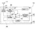
次に発明の実施の形態について説明する。初めに、図1を参照して、基準信号発生装置10の全体構成について説明する。図1は、本実施形態の基準信号発生装置10を概略的に示したブロック図である。
Next, an embodiment of the invention will be described. First, the overall configuration of the
本実施形態の基準信号発生装置10は、携帯電話の基地局、地上デジタル放送の送信局及びWiMAX(Worldwide Interoperability for Microwave Access)の通信設備等に用いられるものであり、接続されるユーザ側の機器に基準信号(基準タイミング信号や基準周波数信号)を提供するものである。以下に、基準信号発生装置10の各部の構成について説明する。
The
図1に示すように、本実施形態の基準信号発生装置10は、制御部20と、GPS受信部21と、スイッチ23と、電圧制御発振器(発振部)24と、分周部25と、温度センサ(環境値取得部)26と、を備える。制御部20は、PLL制御部22と、補助制御部27と、を備えている。また、PLL制御部22、電圧制御発振器24、及び分周部25は、PLL回路(同期回路)44を構成している。
As shown in FIG. 1, the
基準信号発生装置10の入力部41には、GPSアンテナ(GNSSアンテナ)11が接続されている。GPSアンテナ11がGPS衛星(GNSS衛星)から受信した測位信号は、この入力部41を介して、GPS受信部21へ入力される。GPS受信部21は、この測位信号に基づいて測位計算を行うことで、リファレンス信号を生成する。このリファレンス信号は、協定世界時(UTC)の1秒に正確に同期するように適宜較正されている。なお、本実施形態では、GPS受信部21は高感度受信機である。従って、測位信号の信号レベルが小さい場合、リファレンス信号を数秒に1回しか出力できない。
A GPS antenna (GNSS antenna) 11 is connected to the
電圧制御発振器24は、外部から印加される電圧のレベルによって出力する周波数を変更可能に構成されている。電圧制御発振器24としては、例えば水晶振動子を共振器として使用したTCXO(Temperature Compensated Crystal Oscillator、温度補償型水晶発振器)や、OCXO(Oven Controlled Crystal Oscillator、恒温槽付き水晶発振器)を用いることができる。この電圧制御発振器24によって出力された信号は、基準周波数信号として出力部42から外部のユーザ側のシステムへ出力されるとともに、分周部25へ出力される。
The voltage controlled
分周部25は、電圧制御発振器24から入力される基準周波数信号を分周して高い周波数から低い周波数に変換し、得られた位相比較用信号をPLL制御部22へ出力するように構成されている。また、この位相比較用信号は、基準タイミング信号(1PPS信号)として出力部43から外部のユーザ側のシステムに対しても出力される。例えば、電圧制御発振器24が出力する基準周波数が10MHzである場合、分周部25は、電圧制御発振器24が出力する10MHzの信号を分周比1/10000000で分周して、1Hzの位相比較用信号を生成する。
The
PLL制御部22には、前記リファレンス信号と、この位相比較用信号と、が入力される。PLL制御部22は、これらの信号の位相を比較して位相差を求め、その位相差に基づく第1制御信号を生成する。
The reference signal and the phase comparison signal are input to the
また、PLL制御部22は、この位相差信号の高周波成分の遮断及び雑音の除去を行った後に、スイッチ23を介して、第1制御信号を電圧制御発振器24へ出力する。このようにして、PLL制御部22は、リファレンス信号に基づいて電圧制御発振器24を制御する。なお、PLL制御部22は、電圧制御発振器24の出力信号又はそれに基づく信号とリファレンス信号の比較結果を第1制御信号として出力する構成であれば良く、信号の処理方法は任意である。
The
以上に説明した構成によって、PLL回路44のループが構成され、リファレンス信号としての1PPS信号に出力信号が同期するように電圧制御発振器24が制御される。従って、GPS受信部21が1PPS信号を生成して基準信号発生装置10に供給し、当該1PPS信号に対してPLLロックしている限り、経時変化や周囲の温度変化等に起因して電圧制御発振器24の特性の変動が生じたとしても、基準信号発生装置10の基準信号を高精度に保つことができる。
With the configuration described above, a loop of the
次に、マルチパス、妨害電波、及び障害物等によって適切なリファレンス信号を取得できない場合に基準信号発生装置10が行う制御について説明する。基準信号発生装置10は、この制御を行うための構成として、スイッチ23と、温度センサ26と、補助制御部27と、を備える。
Next, control performed by the
なお、この制御は、PLL制御部22が出力した第1制御信号を補助制御部27が補正して第2制御信号を生成して、当該第2制御信号によって電圧制御発振器24を制御する。具体的には、(1)PLLがロックしている間に取得した出力信号の変化及びそのときの温度等から、適切な制御電圧を推定して第2制御信号とする方法と、(2)検出時点における位相差を所定時間掛けて0にするように第2制御信号を設定する方法と、の2つが存在する。以下では、(1)の制御を自走制御と称し、(2)の制御を差分低減制御と称する。
In this control, the
スイッチ23は、PLL制御部22から第1制御信号が入力されるとともに、補助制御部27から第2制御信号が入力される。スイッチ23は、入力された2つの制御信号のうち何れか一方を電圧制御発振器24へ出力する。
The
温度センサ26は、電圧制御発振器24の周囲の温度を取得する。温度センサ26は、温度を直接的に取得する構成であっても良いし、温度を間接的に(例えばOCXOのヒータの電流値等から)取得する構成であっても良い。温度センサ26は、取得した温度を補助制御部27へ出力する。
The
補助制御部27には、GPS受信部21からリファレンス信号が入力されている。補助制御部27は、適切な(正常な)リファレンス信号が連続的に取得できているか否かを判定し、取得できていないと判断した場合は、第2制御信号が電圧制御発振器24に出力されるようにスイッチ23を切り替える。
A reference signal is input from the
また、補助制御部27には、分周部25が出力した位相差が、PLL制御部22を介して入力される。補助制御部27は、この位相差に基づいて、上記の自走制御と差分低減制御のうち何れを行うかを決定する。
Further, the phase difference output from the
ここで、制御部20が行う制御を選択する具体的な方法について図2を参照して説明する。制御部20は、適切なリファレンス信号を連続的に取得できているか否かを判断する(S101)。そして、制御部20(PLL制御部22)は、適切なリファレンス信号を連続的に取得できている場合は、上述のように、リファレンス信号に基づいて電圧制御発振器24を制御する(S102)。
Here, a specific method for selecting the control performed by the
制御部20は、適切なリファレンス信号を連続的に取得できない場合は、出力信号(正確には分周後の出力信号)とリファレンス信号の位相差(差分)が所定の閾値を超えるか否かを判断する(S103)。制御部20(補助制御部27)は、位相差が閾値を超えない場合、上述の自走制御を行う(S104)。また、制御部20(補助制御部27)は、位相差が閾値を超える場合、リファレンス信号を不連続的に取得可能か否かを判断する(S105)。リファレンス信号が不連続的に取得可能であれば、上述の差分低減制御を行う(S106)。なお、制御部20(補助制御部27)は、リファレンス信号を不連続的にも取得できない場合、上述の自走制御を行う(S104)。
When the
次に、自走制御について説明する。補助制御部27には、PLL制御部22から第1制御信号が入力されるとともに、温度センサ26から温度が入力されている。補助制御部27は、温度及び経過時間等に基づいて出力信号のズレを算出し、このズレ量に基づいて制御電圧(制御値)を推定する。そして、補助制御部27は、推定した制御電圧の第2制御信号を生成して、スイッチ23に出力する。
Next, self-running control will be described. The
この自走制御を行うことにより、適切なリファレンス信号が取得できない場合であっても、高精度な基準信号を出力し続けることができる。 By performing this self-running control, it is possible to continue outputting a highly accurate reference signal even when an appropriate reference signal cannot be acquired.
次に、図3を参照して、差分低減制御について説明する。差分低減制御とは、出力信号とリファレンス信号の位相差を所定の時間を掛けて0に近づける制御である。具体的には、補助制御部27は、位相差を減らす方向に第2制御信号の制御電圧を少しずつ変化させる。
Next, the difference reduction control will be described with reference to FIG. Difference reduction control is control in which the phase difference between the output signal and the reference signal is brought close to 0 over a predetermined time. Specifically, the
ここで、図3には、縦軸を位相差として横軸を時間としたグラフが示されている。また、横軸には、リファレンス信号が取得可能な場合にAを付し、リファレンス信号が取得不能な場合にBを付している。つまり、図3に示す例は、信号レベルが低い測位信号を取得した場合の例であり、基本的に5秒に1度リファレンス信号が取得可能であることが分かる。なお、高感度受信機では、信号レベルが低い場合、複数のリファレンス信号を積算してリファレンス信号を生成するため、信号レベルが一定である限り、同じ間隔でリファレンス信号が生成されることが多い。 Here, FIG. 3 shows a graph in which the vertical axis represents phase difference and the horizontal axis represents time. The horizontal axis is indicated by A when the reference signal can be acquired, and B when the reference signal cannot be acquired. That is, the example shown in FIG. 3 is an example when a positioning signal with a low signal level is acquired, and it can be seen that a reference signal can be acquired basically once every 5 seconds. In a high sensitivity receiver, when a signal level is low, a plurality of reference signals are integrated to generate a reference signal. Therefore, as long as the signal level is constant, reference signals are often generated at the same interval.
ここで、図3に示す例では、5秒に1回しかリファレンス信号を取得できないので、適切なリファレンス信号が連続的に取得できないと判断される。また、制御部20は、グラフにおける4秒の時点において、位相差が閾値(下限)を超えていることを検出できるので、差分低減制御を行う。制御部20は、過去のリファレンス信号の取得状況に基づいて、5秒毎にリファレンス信号が取得可能であることを検知し、5秒掛けてこの位相差を0に近づけるように制御を行う。
Here, in the example shown in FIG. 3, since the reference signal can be acquired only once every 5 seconds, it is determined that an appropriate reference signal cannot be acquired continuously. Further, since the
もちろん、差分低減制御を行う5秒の間にも環境は変化するため、5秒後に位相差が0になる訳ではない。しかし、基本的には位相差を大幅に低減できると考えられる。 Of course, since the environment also changes during the 5 seconds during which the difference reduction control is performed, the phase difference does not become 0 after 5 seconds. However, basically, it is considered that the phase difference can be greatly reduced.
このように位相差を瞬時に0に近づけないのは、周波数が大幅に変化することを防止するためである。従って、周波数の変化の許容量によっては5秒よりも早く位相差を0に近づけても良いし、5秒よりも遅く位相差を0に近づけても良い。更には、リファレンス信号の取得間隔に関係ない時間を定め、この時間を掛けて位相差を0に近づけても良い。 The reason why the phase difference is not brought close to 0 instantaneously in this way is to prevent the frequency from changing significantly. Accordingly, depending on the amount of change in frequency, the phase difference may be brought closer to 0 earlier than 5 seconds, or the phase difference may be brought closer to 0 later than 5 seconds. Furthermore, a time not related to the reference signal acquisition interval may be determined, and this phase may be multiplied to bring the phase difference closer to zero.
その後、グラフにおける14秒の時点において、制御部20は、位相差が閾値(上限)を超えていることを検出できるので、差分低減制御を行う。制御部20は、上記と同様に5秒掛けてこの位相差を0に近づけるように制御を行う。
Thereafter, at the time point of 14 seconds in the graph, the
ここで、グラフにおける16秒の時点において、新たにリファレンス信号が取得される。このとき、制御部20は、新しく取得した位相差(求め直した位相差)を用いて、当該位相差を5秒掛けて0に近づけるように制御を修正する。この場合、直近の位相差を利用するため、位相差を効果的に低減させることができる。もちろん、14秒の時点で取得した位相差に基づく差分低減制御を続行することもできる。
Here, a reference signal is newly acquired at the time point of 16 seconds in the graph. At this time, the
上記のように差分低減制御を行うことで、数秒に1回しかリファレンス信号が取得できない場合であっても位相差を効果的に低減させることができる。 By performing the difference reduction control as described above, the phase difference can be effectively reduced even when the reference signal can be acquired only once every few seconds.
なお、閾値は予め値を定めておき、その値を使い続けても良いし、ユーザの設定により変更可能であっても良い。更には、状況(測位信号の信号レベル等)に応じて自動的に値を変化させることもできる。 Note that a threshold value may be determined in advance, and the value may be used continuously, or may be changed by a user setting. Further, the value can be automatically changed according to the situation (signal level of the positioning signal, etc.).
次に、図4を参照して上記実施形態の変形例を説明する。なお、本変形例の説明においては、前述の実施形態と同一又は類似の部材には図面に同一の符号を付し、説明を省略する場合がある。図4に示すように、基準信号発生装置10は、測位信号を処理するための構成として、電圧制御発振器24に加え、シンセサイザ52と、ダウンコンバータ部53と、ベースバンド処理部54と、を備える。
Next, a modification of the above embodiment will be described with reference to FIG. In the description of this modification, the same or similar members as those in the above-described embodiment may be denoted by the same reference numerals in the drawings, and description thereof may be omitted. As shown in FIG. 4, the reference
ダウンコンバータ部53は、この出力信号を復調用信号として使用して、測位信号をダウンコンバートしてIF信号へ変換する。ベースバンド処理部54は、IF信号からベースバンド信号に復調して測位演算部61へ出力する。
The down-
また、基準信号発生装置10は、ベースバンド信号に基づいて基準信号を生成するための構成として、制御部20と、可変分周部71と、分周部72,73と、を備える。また、制御部20は、測位演算部61と、特性算出部62と、周波数補正部64と、タイミング補正部65と、を備える。
The reference
測位演算部61は、ベースバンド処理部54が出力したベースバンド信号に基づいて、自機の位置と、自機側の時計の誤差を公知の方法で計算する。特性算出部62は、電圧制御発振器24の温度特性及び経時変化特性を算出する。
Based on the baseband signal output from the
また、測位演算部61の演算結果からは、シンセサイザ52が出力した出力信号の周波数のズレ及びタイミングのズレを求めることができる。
Further, from the calculation result of the
周波数補正部64は、この出力信号の周波数のズレ等を補正するための補正量を算出する。具体的には、周波数補正部64は、出力信号の周波数のズレ量に基づいて適用する補正量(詳細には分周比)を決定し、可変分周部71へ出力する。可変分周部71には、出力信号が入力されている。可変分周部71は、周波数補正部64によって指定された分周比で出力信号を分周することで、出力信号を補正する。可変分周部71が出力する信号は、分周部72で再び分周されることで、1PPS信号(基準タイミング信号)に変換される。
The
タイミング補正部65は、測位演算部61の演算結果から求められるタイミングのズレに基づいて、1PPS信号のパルスの立ち上がり又は立ち下がりのタイミングをオフセットするための補正量を算出して分周部72へ出力することで、1PPS信号が協定世界時(UTC)に同期するように補正を行う。これにより、基準信号発生装置10は、UTCに同期した1PPS信号を基準タイミング信号として出力部43から外部へ出力することができる。
The
また、適切なリファレンス信号を連続的に取得できない場合、制御部20は、上記の自走制御又は差分低減制御とを行う。制御部20は、上記実施形態と同様に、測位演算部61により得られた周波数やタイミングのズレ(差分)等が閾値を超えていない場合は自走制御を行い、閾値を超えていた場合は差分低減制御を行う。
Moreover, when an appropriate reference signal cannot be acquired continuously, the
自走制御では、制御部20は、特性算出部62が求めた温度特性及び経時変化特性と、温度センサ26が検出した温度等と、に基づいて出力信号の補正量を求め、この補正量により出力信号を補正する。
In the self-running control, the
差分低減制御では、制御部20は、測位演算部61により得られた周波数やタイミングのズレを所定の時間を掛けて0に近づけるように出力信号の補正量を求め、この補正量により出力信号を補正する。
In the difference reduction control, the
以上により、PLL回路を有しない基準信号発生装置においても本願の構成を適用して、数秒に1回程度リファレンス信号が取得できる場合であっても、リファレンス信号を有効に活用して基準信号の誤差を抑えることができる。 As described above, even in a reference signal generator that does not have a PLL circuit, even if the reference signal can be acquired about once every few seconds by applying the configuration of the present application, the reference signal error can be effectively utilized. Can be suppressed.
以上に説明したように、本実施形態の基準信号発生装置10は、電圧制御発振器24と、制御部20と、出力部42,43と、を備える。電圧制御発振器24は、所定の周波数の信号を生成し、出力信号として出力する。制御部20は、電圧制御発振器24の制御又は出力信号の補正を行う。出力部42,43は、出力信号又は当該出力信号に基づく信号を基準信号として出力する。制御部20は、適切なリファレンス信号を連続的に取得している場合は、当該リファレンス信号に基づいて、電圧制御発振器24の制御を行う。制御部20は、適切なリファレンス信号を連続的に取得していない場合は、出力信号とリファレンス信号との位相差(差分)を求め、当該位相差が閾値を超えない場合は、電圧制御発振器24の制御値(制御電圧)を推定して、電圧制御発振器24の制御を行う。制御部20は、適切なリファレンス信号を連続的に取得していない場合であって、差分が閾値を超え、更にリファレンス信号を不連続的に取得している場合は、当該差分を所定の時間を掛けて0に近づける制御である差分低減制御を行う。
As described above, the
これにより、微弱な測位信号を検出することでリファレンス信号の取得間隔が長くなる場合であっても、位相差が大きい場合には差分低減制御を行うことで、リファレンス信号に基づいて求めた位相差を有効に活用して、出力信号の誤差を抑えることができる。 As a result, even if the reference signal acquisition interval is increased by detecting a weak positioning signal, if the phase difference is large, the phase difference obtained based on the reference signal can be obtained by performing difference reduction control. Can be used effectively to suppress errors in the output signal.
以上に本発明の好適な実施の形態及び変形例を説明したが、上記の構成は例えば以下のように変更することができる。 The preferred embodiments and modifications of the present invention have been described above, but the above configuration can be modified as follows, for example.
上記では、発振部の例として、水晶振動子を共振器として使用したTCXO及びOCXOを例として挙げて説明したが、水晶以外(例えばルビジウム)を使用した発振器を代わりに用いることができる。また、デジタル制御発振器を用いることもできる。 In the above description, TCXO and OCXO using a crystal resonator as a resonator have been described as examples of the oscillation unit. However, an oscillator using other than quartz (for example, rubidium) can be used instead. A digitally controlled oscillator can also be used.
上記では、環境値の例として温度を挙げたが、湿度や圧力等も環境値として使用することができる。 In the above description, temperature is given as an example of the environmental value, but humidity, pressure, and the like can also be used as the environmental value.
上記では、位相差を比較するPLL回路を用いているが、周波数差を比較するFLL回路を用いることもできる。この場合、差分低減制御では、周波数差を差分として、周波数差を0に近づける処理を行う。 In the above, a PLL circuit that compares phase differences is used, but an FLL circuit that compares frequency differences can also be used. In this case, in the difference reduction control, a process of making the frequency difference close to 0 using the frequency difference as a difference is performed.
上記では、高感度受信機を使用したことにより、リファレンス信号が数秒に1回しか取得できない事態が発生することを説明したが、例えばGPS受信部21の処理能力が低い場合、同様の事態が発生する。この場合であっても本願の制御を用いることができる。
In the above description, it has been explained that the use of a high-sensitivity receiver causes a situation in which a reference signal can be acquired only once every few seconds. However, for example, when the processing capability of the
上記では、GNSS衛星からの測位信号をリファレンス信号として基準信号を生成する構成であるが、GNSS衛星としては、GPS衛星、GLONASS衛星及びGALILEO衛星等を利用することができる。また、リファレンス信号として、他の機器が出力した信号を利用することもできる。 In the above description, the reference signal is generated using the positioning signal from the GNSS satellite as a reference signal. However, a GPS satellite, a GLONASS satellite, a GALILEO satellite, or the like can be used as the GNSS satellite. In addition, a signal output from another device can be used as the reference signal.
基準信号発生装置10は、1PPSに代えて、PP2S等の1Hz以外の信号を基準タイミング信号として出力部43から出力する構成に変更することができる。
The
基準信号発生装置10が備える各部は、ハードウェアとして構成することに代えて、ソフトウェアにより構成することもできる。
Each unit included in the reference
10 基準信号発生装置
20 制御部
21 GPS受信部
22 PLL制御部
23 スイッチ
24 電圧制御発振器(発振部)
25 分周部
26 温度センサ(環境値取得部)
27 補助制御部
DESCRIPTION OF
25
27 Auxiliary control unit
Claims (7)
前記発振部の制御又は前記出力信号の補正を行う制御部と、
前記出力信号又は当該出力信号に基づく信号を基準信号として出力する出力部と、
を備え、
前記制御部は、
適切なリファレンス信号を連続的に取得している場合は、当該リファレンス信号に基づいて、前記発振部の制御又は前記出力信号の補正を行い、
適切なリファレンス信号を連続的に取得していない場合は、前記出力信号と前記リファレンス信号との位相又は周波数の差分を求め、当該差分が閾値を超えない場合は、前記発振部の制御値又は前記出力信号の補正量を推定して、前記発振部の制御又は前記出力信号の補正を行い、
適切なリファレンス信号を連続的に取得していない場合であって、前記差分が前記閾値を超え、更にリファレンス信号を不連続的に取得している場合は、当該差分を所定の時間を掛けて0に近づける制御である差分低減制御を行うことを特徴とする基準信号発生装置。 An oscillation unit that generates a signal of a predetermined frequency and outputs it as an output signal;
A control unit for controlling the oscillation unit or correcting the output signal;
An output unit that outputs the output signal or a signal based on the output signal as a reference signal;
With
The controller is
If the appropriate reference signal is obtained continuously, based on the reference signal, control the oscillation unit or correct the output signal,
If the appropriate reference signal is not continuously acquired, obtain the phase or frequency difference between the output signal and the reference signal, and if the difference does not exceed the threshold, the control value of the oscillation unit or the Estimating the correction amount of the output signal, performing control of the oscillation unit or correction of the output signal,
If the appropriate reference signal is not continuously acquired, the difference exceeds the threshold value, and if the reference signal is acquired discontinuously, the difference is multiplied by a predetermined time to 0. A reference signal generator characterized by performing difference reduction control which is control close to
前記差分低減制御中に新たな前記リファレンス信号を取得したときに、前記差分を求め直し、求め直した前記差分を所定の時間を掛けて0に近づける制御を行うことを特徴とする基準信号発生装置。 The reference signal generator according to claim 1,
A reference signal generating device characterized in that, when a new reference signal is acquired during the difference reduction control, the difference is recalculated, and the recalculated difference is controlled to approach 0 over a predetermined time. .
前記差分低減制御中に新たな前記リファレンス信号を取得したときに、前記差分を求め直さず、実行中の前記差分低減制御を続行することを特徴とする基準信号発生装置。 The reference signal generator according to claim 1,
A reference signal generation device characterized in that when the new reference signal is acquired during the difference reduction control, the difference reduction control being executed is continued without obtaining the difference again.
前記差分低減制御では、前記リファレンス信号の取得間隔に基づいて決定した時間を掛けて、前記差分を0に近づける制御を行うことを特徴とする基準信号発生装置。 The reference signal generator according to any one of claims 1 to 3,
In the difference reduction control, the reference signal generation device is characterized in that the difference is brought close to 0 by multiplying a time determined based on the reference signal acquisition interval.
前記発振部が使用される環境を示す環境値を取得する環境値取得部を備え、
前記制御部は、適切な前記リファレンス信号を連続的に取得している場合は、前記環境値と前記出力信号との関連性を記憶することを特徴とする基準信号発生装置。 The reference signal generator according to any one of claims 1 to 4, wherein
An environment value acquisition unit that acquires an environment value indicating an environment in which the oscillation unit is used;
The control unit stores a relationship between the environmental value and the output signal when the appropriate reference signal is continuously acquired.
前記差分低減制御を行うか否かを判定するための前記閾値は、設定又は状況に応じて可変であることを特徴とする基準信号発生装置。 A reference signal generator according to any one of claims 1 to 5,
The reference signal generator according to claim 1, wherein the threshold for determining whether or not to perform the difference reduction control is variable according to a setting or a situation.
前記発振部の制御又は前記出力信号の補正を行う制御工程と、
前記出力信号又は当該出力信号に基づく信号を基準信号として出力する出力工程と、
を含み、
前記制御工程では、
適切なリファレンス信号を連続的に取得している場合は、当該リファレンス信号に基づいて、前記発振部の制御又は前記出力信号の補正を行い、
適切なリファレンス信号を連続的に取得していない場合は、前記出力信号と前記リファレンス信号との位相又は周波数の差分を求め、当該差分が閾値を超えない場合は、前記発振部の制御値又は前記出力信号の補正量を推定して、前記発振部の制御又は前記出力信号の補正を行い、
適切なリファレンス信号を連続的に取得していない場合であって、前記差分が前記閾値を超え、更にリファレンス信号を不連続的に取得している場合は、当該差分を所定の時間を掛けて0に近づける制御である差分低減制御を行うことを特徴とする基準信号発生方法。 An oscillation process for generating a signal of a predetermined frequency and outputting it as an output signal from the oscillation unit;
A control step of controlling the oscillation unit or correcting the output signal;
An output step of outputting the output signal or a signal based on the output signal as a reference signal;
Including
In the control step,
If the appropriate reference signal is obtained continuously, based on the reference signal, control the oscillation unit or correct the output signal,
If the appropriate reference signal is not continuously acquired, obtain the phase or frequency difference between the output signal and the reference signal, and if the difference does not exceed the threshold, the control value of the oscillation unit or the Estimating the correction amount of the output signal, performing control of the oscillation unit or correction of the output signal,
If the appropriate reference signal is not continuously acquired, the difference exceeds the threshold value, and if the reference signal is acquired discontinuously, the difference is multiplied by a predetermined time to 0. A reference signal generation method characterized by performing difference reduction control which is control close to.
Priority Applications (1)
| Application Number | Priority Date | Filing Date | Title |
|---|---|---|---|
| JP2013083369A JP2014207534A (en) | 2013-04-11 | 2013-04-11 | Reference signal generation device and reference signal generation method |
Applications Claiming Priority (1)
| Application Number | Priority Date | Filing Date | Title |
|---|---|---|---|
| JP2013083369A JP2014207534A (en) | 2013-04-11 | 2013-04-11 | Reference signal generation device and reference signal generation method |
Publications (1)
| Publication Number | Publication Date |
|---|---|
| JP2014207534A true JP2014207534A (en) | 2014-10-30 |
Family
ID=52120783
Family Applications (1)
| Application Number | Title | Priority Date | Filing Date |
|---|---|---|---|
| JP2013083369A Pending JP2014207534A (en) | 2013-04-11 | 2013-04-11 | Reference signal generation device and reference signal generation method |
Country Status (1)
| Country | Link |
|---|---|
| JP (1) | JP2014207534A (en) |
Cited By (1)
| Publication number | Priority date | Publication date | Assignee | Title |
|---|---|---|---|---|
| JP2016119540A (en) * | 2014-12-19 | 2016-06-30 | 古野電気株式会社 | Reference signal generation device and reference signal generation method |
-
2013
- 2013-04-11 JP JP2013083369A patent/JP2014207534A/en active Pending
Cited By (1)
| Publication number | Priority date | Publication date | Assignee | Title |
|---|---|---|---|---|
| JP2016119540A (en) * | 2014-12-19 | 2016-06-30 | 古野電気株式会社 | Reference signal generation device and reference signal generation method |
Similar Documents
| Publication | Publication Date | Title |
|---|---|---|
| US8736394B2 (en) | Reference frequency generating device | |
| US10187074B2 (en) | Timing signal generation device, electronic device, and moving object | |
| US10782415B2 (en) | Timing signal generation device and electronic apparatus | |
| KR101822222B1 (en) | Navigation signal transmitter and navigation signal generating method | |
| JP2016225708A (en) | Timing signal generation device, electronic apparatus and moving body | |
| US10222482B2 (en) | Position information generation device, timing signal generation device, electronic apparatus, and moving object | |
| JP6276700B2 (en) | Reference signal generator and reference signal generation method | |
| WO2014045929A1 (en) | Standard signal generation device, gnss module, and standard signal generation method | |
| JP2014207534A (en) | Reference signal generation device and reference signal generation method | |
| JP2014060682A (en) | Oscillator control method, reference signal generation device and oven-controlled oscillator | |
| JP6452434B2 (en) | Reference signal generator and reference signal generation method | |
| JP6681231B2 (en) | Reference signal generator and reference signal generation method | |
| JP2017153024A (en) | Reference frequency generation device | |
| JP2008281538A (en) | Gps (global positioning system) receiver | |
| JP2017138197A (en) | Timing signal generating device, electronic equipment, and mobile body | |
| JP5064358B2 (en) | Reference signal generator | |
| WO2016088449A1 (en) | Reference signal generation device | |
| JP6534200B2 (en) | Reference signal generator | |
| JP2016195347A (en) | Timing signal generator, electronic apparatus and moving body | |
| JP2017138234A (en) | Timing signal generating device, electronic equipment, and mobile body | |
| JP2016220157A (en) | Standard signal generating device | |
| WO2016199592A1 (en) | Receiving device and receiving method | |
| JP2017059971A (en) | Timing signal generator, electronic apparatus and movable body | |
| JP2016063392A (en) | Reference signal generator |