JP2014204635A - Cord short-circuit detection circuit, and outlet device - Google Patents
Cord short-circuit detection circuit, and outlet device Download PDFInfo
- Publication number
- JP2014204635A JP2014204635A JP2013081383A JP2013081383A JP2014204635A JP 2014204635 A JP2014204635 A JP 2014204635A JP 2013081383 A JP2013081383 A JP 2013081383A JP 2013081383 A JP2013081383 A JP 2013081383A JP 2014204635 A JP2014204635 A JP 2014204635A
- Authority
- JP
- Japan
- Prior art keywords
- circuit
- voltage
- output
- cord short
- specific
- Prior art date
- Legal status (The legal status is an assumption and is not a legal conclusion. Google has not performed a legal analysis and makes no representation as to the accuracy of the status listed.)
- Granted
Links
Images
Abstract
Description
本発明は、コード短絡を検出するコード短絡検出回路、及びコード短絡が発生したら電路を遮断する機能を備えたコンセント装置に関する。 The present invention relates to a cord short-circuit detection circuit for detecting a cord short-circuit, and an outlet device having a function of interrupting an electric circuit when a cord short-circuit occurs.
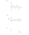
このコード短絡は、最初は撚り線1本程度の電線が短絡する所謂ヒゲコード短絡からスタートすることが知られている。よって、このヒゲコード短絡を精度良く検出できれば、コード短絡の初期を検出でき電線の焼損や火災が発生する前に対処できる。そのため本発明者は、ヒゲコード短絡を精度良く検出できる回路を特許文献1で提案した。
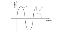
これは、ヒゲコード短絡では数百アンペアの電流は流れず、電圧波形をみると図5に示すような独特な形状を示すことが実験から確認されており、Sで示すようなピーク付近から大きく切り欠いたような波形が発生する。この波形は過電流や突入電流の波形とは異なるため、この特徴ある特定の歪んだ電圧波形を2つの閾値を設定して検出し、コード短絡の初期の段階を検出可能とした。
It is known that this cord short circuit starts at first from a so-called beard cord short circuit in which an electric wire of about one stranded wire is short-circuited. Therefore, if the whisker cord short circuit can be detected with high accuracy, the initial stage of the cord short circuit can be detected, and it can be dealt with before the burnout of the electric wire or the fire occurs. Therefore, the present inventor has proposed a circuit capable of detecting a whisker code short circuit with high accuracy in
It has been confirmed from experiments that a current of several hundred amperes does not flow when a whisker cord is short-circuited, and the voltage waveform shows a unique shape as shown in FIG. A missing waveform is generated. Since this waveform is different from the waveforms of overcurrent and inrush current, this characteristic specific distorted voltage waveform is detected by setting two thresholds, and the initial stage of the cord short circuit can be detected.
上記特許文献1の技術は、図5に示すようなヒゲコード短絡の発生による独特の電圧波形を検出することはできた。しかしながら、例えば一度に多量の電灯をオンした場合等に発生する所謂突入電流によって一瞬電圧が低下する現象を完全に排除することができず、ヒゲコード短絡に伴う特定の電圧歪みと誤認識してしまう場合があり、突入電流対策が十分ではなかった。
The technique of
そこで、本発明はこのような問題点に鑑み、突入電流に反応すること無くヒゲコード短絡を高い精度で検出し、コード短絡発生を早期に検出できるコード短絡検出回路、及びコード短絡が発生したら電路を遮断するコンセント装置を提供することを目的としている。 Therefore, in view of such a problem, the present invention detects a whisker cord short-circuit with high accuracy without reacting to an inrush current, a cord short-circuit detection circuit capable of early detection of a cord short-circuit occurrence, and an electric circuit when a cord short-circuit occurs. The object is to provide an outlet device that shuts off.
上記課題を解決する為に、請求項1の発明に係るコード短絡検出回路は、負荷へ商用電力を供給する電路の電圧波形を整流する整流回路と、ヒゲコード短絡発生による特定の波形歪みを検出するために、商用電圧波形の波高値を下回る特定の2値と整流回路出力電圧の瞬時値とを比較し、瞬時値が特定の2値の間にある間は一定の信号を出力するウインドウコンパレータ回路と、ウインドウコンパレータ回路の出力を基に特定の波形歪みの発生を判断する特定歪み判定回路と、整流回路が出力する電圧波形の波高値の低下を監視する電圧監視回路と、特定歪み判定回路が特定歪み発生と判断し、且つ電圧監視回路が電圧の低下がないと判断したら、コード短絡発生と判定する判定回路とを有することを特徴とする。
この構成によれば、特定歪み判定回路がヒゲコード短絡発生による特定歪み発生と判断しても、電圧監視回路が突入電流による電路電圧の低下を検出したらコード短絡発生を判断しないため、突入電流による電圧低下を排除してコード短絡の発生を早期に且つ高精度で検出できる。
In order to solve the above problems, a cord short-circuit detection circuit according to the first aspect of the present invention detects a specific waveform distortion caused by a rectifier circuit that rectifies a voltage waveform of an electric circuit that supplies commercial power to a load, and a whisker cord short-circuit occurrence. Therefore, a window comparator circuit that compares a specific binary value lower than the peak value of the commercial voltage waveform with an instantaneous value of the rectifier circuit output voltage and outputs a constant signal while the instantaneous value is between the specific binary values A specific distortion determination circuit that determines the occurrence of a specific waveform distortion based on the output of the window comparator circuit, a voltage monitoring circuit that monitors a decrease in the peak value of the voltage waveform output from the rectifier circuit, and a specific distortion determination circuit And a determination circuit that determines that a cord short-circuit has occurred when it is determined that specific distortion has occurred and the voltage monitoring circuit determines that there is no voltage drop.
According to this configuration, even if the specific distortion determination circuit determines that a specific distortion has occurred due to the occurrence of a mustache cord short circuit, the voltage monitoring circuit does not determine the occurrence of a cord short circuit if it detects a decrease in the circuit voltage due to the inrush current. The occurrence of the cord short circuit can be detected early and with high accuracy by eliminating the decrease.
請求項2の発明に係るコンセント装置は、負荷が接続されるコンセントと、コンセントに商用電力を供給するための電路と、電路上に設けられて電路の開閉を行う開閉手段と、開閉手段を開動作させる遮断手段と、請求項1に記載のコード短絡検出回路と、コード短絡検出回路が出力するコード短絡発生信号を基に遮断手段を駆動する出力回路とを有することを特徴とする。
この構成によれば、コード短絡が発生を早期に検知してコンセント出力を停止するので、コード短絡による火災発生を確実に防止できる。
According to a second aspect of the present invention, there is provided an outlet device in which a load is connected, an electric circuit for supplying commercial power to the electric outlet, an opening / closing means provided on the electric circuit for opening and closing the electric circuit, and an opening / closing means. It is characterized by having a shut-off means to be operated, a cord short-circuit detecting circuit according to
According to this configuration, since the occurrence of the cord short circuit is detected early and the outlet output is stopped, it is possible to reliably prevent the occurrence of a fire due to the cord short circuit.
本発明に係るコード短絡検出回路によれば、特定歪み判定回路がヒゲコード短絡発生による特定歪み発生と判断しても、電圧監視回路が突入電流による電路電圧の低下を検出したらコード短絡発生を判断しないため、突入電流による電圧低下を排除して、コード短絡の発生を早期に且つ高精度で検出できる。
また、本発明のコンセント装置によれば、コード短絡が発生を早期に検知してコンセント出力を停止するので、コード短絡による火災発生を確実に防止できる。
According to the cord short circuit detection circuit according to the present invention, even if the specific distortion determination circuit determines that the specific distortion occurs due to the beard code short circuit occurrence, if the voltage monitoring circuit detects a decrease in the circuit voltage due to the inrush current, the code short circuit detection is not determined. Therefore, the voltage drop due to the inrush current is eliminated, and the occurrence of the cord short circuit can be detected early and with high accuracy.
Further, according to the outlet device of the present invention, since the occurrence of the cord short circuit is detected at an early stage and the outlet output is stopped, it is possible to reliably prevent the occurrence of a fire due to the cord short circuit.
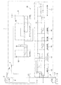
以下、本発明を具体化した実施の形態を、図面を参照して詳細に説明する。図1は本発明に係るコンセント装置の一例を示す回路図であり、1はコンセント装置、2は分電盤等から供給される商用電源、3はテレビや照明等の負荷、4は負荷3を接続するコンセント、L1は商用電源2からコンセント装置1に至る電路、L2はコンセント4に接続されたプラグ(図示せず)から負荷3に至る負荷電路である。尚、コンセント装置1は通常は壁面に埋設設置される。
DESCRIPTION OF THE PREFERRED EMBODIMENTS Embodiments embodying the present invention will be described below in detail with reference to the drawings. FIG. 1 is a circuit diagram showing an example of an outlet device according to the present invention, in which 1 is an outlet device, 2 is a commercial power source supplied from a distribution board, etc., 3 is a load such as a television or lighting, and 4 is a
コンセント装置1は、図1に示すように商用電源2が接続された電路L1を接続する電源接続部からコンセント4に至る内部電路L3上に設けた開閉接点6、開閉接点6を開動作させるプランジャ7aを備えた電磁コイル7、電磁コイル7を駆動するための出力回路8、コード短絡を検出するコード短絡検出回路10を備えている。
As shown in FIG. 1, the
コード短絡検出回路10は、内部電路L3の電路電圧を全波整流する整流回路11、コード短絡検出回路10の各部に電源を供給する電源回路12、整流回路11が整流した電圧波形を特定の2値と比較するウインドウコンパレータ回路13、ウインドウコンパレータ回路13の出力波形を成形する波形成形回路14、波形成形回路14の出力波形を積分する積分回路15、積分回路15の出力を所定の閾値と比較して特定の歪み発生を判定する特定歪み判定回路としての第1比較回路16、第1比較回路16の出力を受けてパルス信号を出力する第1ワンショットパルス回路17、整流回路11が整流した電圧波形を特定の閾値と比較する電圧監視回路としての第2比較回路18、第2比較回路18の出力及び第1ワンショットパルス回路17の出力を基にヒゲコード短絡発生を判定してパルス信号を出力する判定回路としての第2ワンショットパルス回路19等を備えている。
The cord short-
上記の如く構成されたコード短絡検出回路10の動作は以下の様である。図2〜図4の波形説明図を参照して説明する。ウインドウコンパレータ回路13は、予め設定した電路電圧波形(商用電圧波形)の波高値を下回る特定の2値(高い方の第1固定値EH、及び低い方の第2固定値ELの2値)と整流回路11が出力する電圧波形とを比較し、この2つの固定値の間に電路電圧の瞬時値がある間は特定の信号を出力する。
具体的に、ウインドウコンパレータ回路13には電路電圧が分圧されて入力され、例えば10分の1に分圧された電圧が入力される。その結果、波高値約14ボルトの電圧が入力される。この値の電圧に対しては、例えば第1固定値EH=5ボルト、第2固定値EL=1ボルトに設定される。この設定により、上記図5に示すヒゲコード短絡により発生する電路電圧の独特の変化を検出することが可能となる。
The operation of the cord short
Specifically, the electric circuit voltage is divided and inputted to the
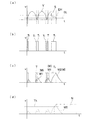
ここで、図2はコード短絡検出回路10の要部の波形を示し、図2(a)はウインドウコンパレータ回路13に入力される電圧波形Vと特定の2値EH,ELとの関係、図2(b)は波形成形回路14の出力、図2(c)は積分回路15の出力、図2(d)は第1比較回路16の出力波形をそれぞれ示している。
図2(a)に示すように、ヒゲコード短絡により発生する電路電圧の独特の変化を挟むように特定の2値EH,ELは設定される。そして波形成形回路14が、図2(b)に示すように正常時は時間幅T1の矩形波を出力するが、ヒゲコード短絡が発生したら長い時間幅T2の矩形波を出力する。ヒゲコード短絡が発生すると特徴ある電圧波形が発生するため、瞬時値が数十ボルトから波高値の約50%となる70ボルト程度の間に数ms留まる状態が発生すると見ることができる。よって、第1固定値EHと第2固定値ELを上記の如く設定することでその状態を検出し、ヒゲコード短絡が検出可能となる。
Here, FIG. 2 shows the waveform of the main part of the cord short
As shown in FIG. 2A, specific binary values EH and EL are set so as to sandwich a unique change in the circuit voltage caused by a beard code short circuit. As shown in FIG. 2B, the
そして積分回路15は、波形成形回路14が出力する矩形波を積分して図2(c)に示すような波形の信号Mを出力する。図2(c)に示すように、正常時の正弦波に対してはピーク値の小さい波形M1を出力するが、コード短絡(ヒゲコード短絡)により発生するT2の矩形波を受けて、M2に示すように大きなピーク値の波形が出力される。
The integrating
第1比較回路16は、積分回路15の出力を所定の閾値Thと比較し、閾値Thを越えたら図2(d)に示すように信号Nを出力する。こうして、通常の正弦波の場合は出力されることが無く、図5のSに示すような歪みが発生したら信号Nが出力される。そして、第1ワンショットパルス回路17が、第1比較回路16の出力Nを受けてパルス信号を出力する。
The
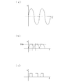
一方、第2比較回路18は、整流された電路電圧波形を所定の閾値と比較して、電路電圧の瞬時値が所定値に達しなければ、出力を発生しない。図3,図4は、この第2比較回路18の出力を具体的に示し、図3は過大な突入電流の発生により電路電圧が大きく減少した場合、図4は電路電圧が正常な通常状態をそれぞれ示し、Vthは所定の閾値を示している。図3,図4に示すように、第2比較回路18は通常状態では電圧のピークに合わせて矩形波を常時出力するが、突入電流発生時は図3(c)に示すように出力が一時的に無くなる。
第2ワンショットパルス回路19は、この第2比較回路18及び第1ワンショットパルス回路17の出力信号を受けて、双方が矩形波を出力したら即ち[H]の信号を出力したら、出力回路8を起動させるパルス信号を出力する。
On the other hand, the
The second one-
出力回路8はこの信号を受けてオン動作し、電磁コイル7を駆動してプランジャ7aが引き外し動作する。その結果、開閉接点6は開動作し、負荷3への電力の供給は停止される。
The
このように、第1比較回路16が特定歪みの発生と判断しても、第2比較回路18が突入電流による電路電圧の低下を検出したらコード短絡発生と判断しないため、突入電流による電圧低下を排除して、コード短絡の発生を高精度で検出できる。そして、ヒゲコード短絡を検出して遮断動作するため、コード短絡を早期に検出できる。
また、コード短絡が発生したらそれを検知して電路を遮断してコンセント出力を停止するので、コード短絡による火災発生を確実に防止できる。
Thus, even if the
Also, if a cord short-circuit occurs, it is detected and the electrical circuit is shut off to stop the outlet output, so that a fire due to a cord short-circuit can be reliably prevented.
尚、上記実施形態は、コード短絡検出回路10をコンセントに組み込んだ場合を説明したが、分岐ブレーカ等の回路遮断器に内蔵させても良いし、コンセントに接続して使用されるタップコンセントに内蔵させても良い。
また、コンセント装置に遮断機能を設けているが、コード短絡が発生したら音やLEDの発光で通知する構成としても良い。
In addition, although the said embodiment demonstrated the case where the cord short
Moreover, although the interruption | blocking function is provided in the outlet apparatus, it is good also as a structure which notifies by sound or light emission of LED, when a cord short circuit generate | occur | produces.
1・・コンセント装置、4・・コンセント、6・・開閉接点(開閉手段)、7・・電磁コイル(遮断手段)、8・・出力回路、10・・コード短絡検出回路、11・・整流回路、13・・ウィンドウコンパレータ回路、16・・第1比較回路(特定歪み検出回路)、18・・第2比較回路(電圧監視回路)、19・・第2ワンショットパルス回路(判定回路)、L3・・内部電路(電路)。
1 .... Outlet device, 4 .... Outlet, 6 .... Open / close contact (open / close means), 7 .... Electromagnetic coil (breaking means), 8 .... Output circuit, 10 .... Cord short circuit detection circuit, 11 .... Rectifier circuit , 13 .. Window comparator circuit, 16... First comparison circuit (specific distortion detection circuit), 18... Second comparison circuit (voltage monitoring circuit), 19 .. Second one-shot pulse circuit (determination circuit),
Claims (2)
ヒゲコード短絡発生による特定の波形歪みを検出するために、商用電圧波形の波高値を下回る特定の2値と前記整流回路出力電圧の瞬時値とを比較し、瞬時値が前記特定の2値の間にある間は一定の信号を出力するウインドウコンパレータ回路と、
前記ウインドウコンパレータ回路の出力を基に前記特定の波形歪みの発生を判断する特定歪み判定回路と、
前記整流回路が出力する電圧波形の波高値の低下を監視する電圧監視回路と、
前記特定歪み判定回路が特定歪み発生と判断し、且つ前記電圧監視回路が電圧の低下がないと判断したら、コード短絡発生と判定する判定回路とを有することを特徴とするコード短絡検出回路。 A rectifier circuit that rectifies the voltage waveform of the electric circuit that supplies commercial power to the load;
In order to detect a specific waveform distortion due to the occurrence of a whisker code short circuit, a specific binary value lower than a peak value of a commercial voltage waveform is compared with an instantaneous value of the rectifier circuit output voltage, and the instantaneous value is between the specific binary values. A window comparator circuit that outputs a constant signal while
A specific distortion determination circuit that determines the occurrence of the specific waveform distortion based on an output of the window comparator circuit;
A voltage monitoring circuit for monitoring a drop in the peak value of the voltage waveform output by the rectifier circuit;
A cord short circuit detection circuit comprising: a determination circuit that determines that a cord short circuit has occurred when the specific distortion determination circuit determines that a specific distortion has occurred and the voltage monitoring circuit determines that there is no voltage drop.
Priority Applications (1)
| Application Number | Priority Date | Filing Date | Title |
|---|---|---|---|
| JP2013081383A JP6058455B2 (en) | 2013-04-09 | 2013-04-09 | Cord short-circuit detection circuit and outlet device |
Applications Claiming Priority (1)
| Application Number | Priority Date | Filing Date | Title |
|---|---|---|---|
| JP2013081383A JP6058455B2 (en) | 2013-04-09 | 2013-04-09 | Cord short-circuit detection circuit and outlet device |
Publications (2)
| Publication Number | Publication Date |
|---|---|
| JP2014204635A true JP2014204635A (en) | 2014-10-27 |
| JP6058455B2 JP6058455B2 (en) | 2017-01-11 |
Family
ID=52354609
Family Applications (1)
| Application Number | Title | Priority Date | Filing Date |
|---|---|---|---|
| JP2013081383A Active JP6058455B2 (en) | 2013-04-09 | 2013-04-09 | Cord short-circuit detection circuit and outlet device |
Country Status (1)
| Country | Link |
|---|---|
| JP (1) | JP6058455B2 (en) |
Cited By (1)
| Publication number | Priority date | Publication date | Assignee | Title |
|---|---|---|---|---|
| DE102014226164A1 (en) * | 2014-12-17 | 2016-06-23 | Bayerische Motoren Werke Aktiengesellschaft | Semiconductor line protection |
Citations (7)
| Publication number | Priority date | Publication date | Assignee | Title |
|---|---|---|---|---|
| JPS57103516U (en) * | 1980-12-16 | 1982-06-25 | ||
| JP2001157355A (en) * | 1999-11-26 | 2001-06-08 | Kawamura Electric Inc | Wiring breaker |
| US6262872B1 (en) * | 1999-06-03 | 2001-07-17 | General Electric Company | Electronic trip unit with user-adjustable sensitivity to current spikes |
| JP2007159344A (en) * | 2005-12-08 | 2007-06-21 | Nec Computertechno Ltd | Current limiting circuit, power-supply circuit, and current limiting method |
| JP2011171244A (en) * | 2010-02-22 | 2011-09-01 | Kawamura Electric Inc | Circuit breaker |
| JP2012085425A (en) * | 2010-10-08 | 2012-04-26 | Kawamura Electric Inc | Cord short-circuit detection circuit and outlet device |
| JP2012186953A (en) * | 2011-03-07 | 2012-09-27 | Kawamura Electric Inc | Cord short-circuit detection circuit and outlet device |
-
2013
- 2013-04-09 JP JP2013081383A patent/JP6058455B2/en active Active
Patent Citations (7)
| Publication number | Priority date | Publication date | Assignee | Title |
|---|---|---|---|---|
| JPS57103516U (en) * | 1980-12-16 | 1982-06-25 | ||
| US6262872B1 (en) * | 1999-06-03 | 2001-07-17 | General Electric Company | Electronic trip unit with user-adjustable sensitivity to current spikes |
| JP2001157355A (en) * | 1999-11-26 | 2001-06-08 | Kawamura Electric Inc | Wiring breaker |
| JP2007159344A (en) * | 2005-12-08 | 2007-06-21 | Nec Computertechno Ltd | Current limiting circuit, power-supply circuit, and current limiting method |
| JP2011171244A (en) * | 2010-02-22 | 2011-09-01 | Kawamura Electric Inc | Circuit breaker |
| JP2012085425A (en) * | 2010-10-08 | 2012-04-26 | Kawamura Electric Inc | Cord short-circuit detection circuit and outlet device |
| JP2012186953A (en) * | 2011-03-07 | 2012-09-27 | Kawamura Electric Inc | Cord short-circuit detection circuit and outlet device |
Cited By (1)
| Publication number | Priority date | Publication date | Assignee | Title |
|---|---|---|---|---|
| DE102014226164A1 (en) * | 2014-12-17 | 2016-06-23 | Bayerische Motoren Werke Aktiengesellschaft | Semiconductor line protection |
Also Published As
| Publication number | Publication date |
|---|---|
| JP6058455B2 (en) | 2017-01-11 |
Similar Documents
| Publication | Publication Date | Title |
|---|---|---|
| US9246402B2 (en) | Converter and semiconductor device | |
| US8390964B2 (en) | Protection apparatus and method for an isolated type power supply | |
| US9985543B1 (en) | Switching power supply | |
| KR101333648B1 (en) | Arc detection apparatus and method | |
| JP6895647B2 (en) | Arc detection circuit, switch system, power conditioner system and arc detection method | |
| JP6000193B2 (en) | DC arc detector | |
| CN103368143A (en) | Overpower protection circuit for current-type switching power supply | |
| WO2018150877A1 (en) | Arc detection circuit, switch system, power conditioner system and arc detection method | |
| JP5683329B2 (en) | Cord short circuit detection circuit and outlet device | |
| US20170062163A1 (en) | Latching relay drive circuit | |
| JP6165023B2 (en) | Cord short circuit detection circuit and outlet device | |
| JP6058455B2 (en) | Cord short-circuit detection circuit and outlet device | |
| JP2006246666A (en) | Air conditioner | |
| CN110383613B (en) | Electronic circuit breaker | |
| JP6372926B2 (en) | Switch | |
| TWI625032B (en) | Low phase surge protection device | |
| JP6211865B2 (en) | Cord short circuit detection circuit and outlet device | |
| KR102300128B1 (en) | Instantaneous power failure compensation device for SMPS | |
| TW201639281A (en) | Power supply apparatus and power processing method | |
| JP6513546B2 (en) | LED power supply | |
| KR20150070590A (en) | Circuit for driving synchronous rectifier and power supply apparatus including the same | |
| JP5587127B2 (en) | Cord short circuit detection circuit and outlet device | |
| TWI704737B (en) | Over power protection circuit, charger and over power protection method | |
| US20190027921A1 (en) | Low phase surge protection device | |
| JP7279879B2 (en) | Signal converter and motor drive system |
Legal Events
| Date | Code | Title | Description |
|---|---|---|---|
| A621 | Written request for application examination |
Free format text: JAPANESE INTERMEDIATE CODE: A621 Effective date: 20160222 |
|
| A977 | Report on retrieval |
Free format text: JAPANESE INTERMEDIATE CODE: A971007 Effective date: 20161108 |
|
| TRDD | Decision of grant or rejection written | ||
| A01 | Written decision to grant a patent or to grant a registration (utility model) |
Free format text: JAPANESE INTERMEDIATE CODE: A01 Effective date: 20161115 |
|
| A61 | First payment of annual fees (during grant procedure) |
Free format text: JAPANESE INTERMEDIATE CODE: A61 Effective date: 20161207 |
|
| R150 | Certificate of patent or registration of utility model |
Ref document number: 6058455 Country of ref document: JP Free format text: JAPANESE INTERMEDIATE CODE: R150 |
|
| R250 | Receipt of annual fees |
Free format text: JAPANESE INTERMEDIATE CODE: R250 |
|
| R250 | Receipt of annual fees |
Free format text: JAPANESE INTERMEDIATE CODE: R250 |