JP2014203604A - Lighting device - Google Patents

Lighting device Download PDF

Info

Publication number
JP2014203604A
JP2014203604A JP2013077337A JP2013077337A JP2014203604A JP 2014203604 A JP2014203604 A JP 2014203604A JP 2013077337 A JP2013077337 A JP 2013077337A JP 2013077337 A JP2013077337 A JP 2013077337A JP 2014203604 A JP2014203604 A JP 2014203604A
Authority
JP
Japan
Prior art keywords
light
light source
optical
optical element
shade
Prior art date
Legal status (The legal status is an assumption and is not a legal conclusion. Google has not performed a legal analysis and makes no representation as to the accuracy of the status listed.)
Pending
Application number
JP2013077337A
Other languages
Japanese (ja)
Other versions
JP2014203604A5 (en
Inventor
誠治 村田
Seiji Murata
誠治 村田
別井 圭一
Keiichi Betsui
圭一 別井
Current Assignee (The listed assignees may be inaccurate. Google has not performed a legal analysis and makes no representation or warranty as to the accuracy of the list.)
Hitachi Appliances Inc
Original Assignee
Hitachi Appliances Inc
Priority date (The priority date is an assumption and is not a legal conclusion. Google has not performed a legal analysis and makes no representation as to the accuracy of the date listed.)
Filing date
Publication date
Application filed by Hitachi Appliances Inc filed Critical Hitachi Appliances Inc
Priority to JP2013077337A priority Critical patent/JP2014203604A/en
Publication of JP2014203604A publication Critical patent/JP2014203604A/en
Publication of JP2014203604A5 publication Critical patent/JP2014203604A5/ja
Pending legal-status Critical Current

Links

Images

Abstract

PROBLEM TO BE SOLVED: To provide a technology which is suitable for improving the luminance uniformity of a light emitting face of a lighting device.SOLUTION: This lighting device comprises a plurality of light sources (1), and a shade (3) as a shield case which has transparency, and diffuses and emits light from the light sources. An optical member (2) in which a plurality of optical elements (21) having lens shapes for refracting the light from the light sources are two-dimensionally aligned is arranged between a plurality of the light sources (1) and the shade (3), and emission light from the light sources (1) is radiated to the shade (3) via the optical elements (21). The optical elements (21) are arranged in a plurality of numbers so as to correspond to a plurality of the light sources (1), respectively.

Description

本発明は、例えばシーリングライトなどの照明装置に関する。   The present invention relates to an illumination device such as a ceiling light.

光源として、例えばLED(Light Emitting Diode)を使用したシーリングライトやベース照明等の照明装置では、照明装置の光照射側の外装ケースとなるセードと呼ばれる透過性を有する樹脂等の材質で構成される部材を有している。セードとは、照明装置の照射面となる部材であり、照明装置に搭載された光源からの光を拡散しながら透過する機能を有している。このセードを透過し出射した光が照明装置の照射光となって、所定範囲或いは領域を照明する。   In a lighting device such as a ceiling light or base illumination using, for example, an LED (Light Emitting Diode) as a light source, it is made of a material such as a resin having transparency called a shade that becomes an exterior case on the light irradiation side of the lighting device. It has a member. The seed is a member serving as an irradiation surface of the lighting device, and has a function of transmitting light from a light source mounted on the lighting device while diffusing. The light transmitted through the shade and emitted is used as illumination light of the illumination device to illuminate a predetermined range or region.

かかる照明装置、例えばシーリングライトでは、セード上で光源に対応する位置の部分が局所的に輝度が高くなるような極端な明暗が発生しないこと、すなわち均一な照度分布が得られていることが望ましい。   In such an illuminating device, for example, a ceiling light, it is desirable that an extreme brightness and darkness in which a portion at a position corresponding to the light source on the shade does not increase in brightness locally, that is, a uniform illuminance distribution is obtained. .

均一な照度分布を得るための従来技術として、例えば特許文献1に記載のものが知られている。特許文献1には、指向性のある複数の光源を実装した基板を備えた照明装置において、光源が基板上において光が均一となるように配置され、光源からの光を拡散する拡散板を、光源から拡散板までの距離が複数の光源間の距離より大きくなるように配置することで、光源の配置による拡散板上の明暗の発生を抑えることを開示している。   As a conventional technique for obtaining a uniform illuminance distribution, for example, one described in Patent Document 1 is known. In Patent Literature 1, in a lighting device including a substrate on which a plurality of directional light sources are mounted, a diffusion plate is disposed so that light is uniform on the substrate and diffuses light from the light source. It discloses that the occurrence of light and darkness on the diffusion plate due to the arrangement of the light sources is suppressed by arranging the distance from the light source to the diffusion plate to be larger than the distance between the plurality of light sources.

特許第4996998号公報Japanese Patent No. 4996998

上記特許文献1に記載の構成では、拡散板と光源間の距離が光源の配置ピッチよりも大きく確保する必要がある。この場合、照明装置の厚さ(照明装置の照射面と直交する方向の寸法)が増し、小型、薄型の照明装置の実現が困難となる。また拡散板と光源間の距離を短くするために光源の配置ピッチを短くしようとすると多数の光源が必要となり、発熱の増加、部品点数及びコストの上昇の問題が生じる。また、照明光の照度分布の均一性を向上させようとして拡散板の光拡散度を高くすると、拡散板の透過率が減少するため照明光の輝度や発光効率が低下する。   In the configuration described in Patent Document 1, it is necessary to ensure that the distance between the diffusion plate and the light source is larger than the arrangement pitch of the light sources. In this case, the thickness of the lighting device (dimension in the direction orthogonal to the irradiation surface of the lighting device) increases, and it becomes difficult to realize a small and thin lighting device. In order to shorten the distance between the diffuser plate and the light source, an attempt to shorten the arrangement pitch of the light sources requires a large number of light sources, resulting in problems of increased heat generation, the number of parts and cost. Further, if the light diffusion degree of the diffusion plate is increased in order to improve the uniformity of the illuminance distribution of the illumination light, the transmittance of the diffusion plate is reduced, so that the luminance and luminous efficiency of the illumination light are reduced.

本発明は、上記従来技術の課題に鑑みて為されたものであり、複数の光源を備えた照明装置において、照明装置の厚さや光源数の増加を抑制しつつ照明光の明るさ及び照度均一性を向上するために好適な技術を提供するものである。   The present invention has been made in view of the above-described problems of the prior art, and in an illumination device including a plurality of light sources, the brightness of the illumination light and the illuminance uniformity are suppressed while suppressing an increase in the thickness of the illumination device and the number of light sources. The present invention provides a suitable technique for improving the performance.

本発明は例えば特許請求の範囲に記載された構成を特徴とするものである。より具体的には、本発明に係る照明装置は、複数の光源と、透光性を有し該光源からの光を拡散して出射するための、外装ケースとしてのセードとを備えた照明装置において、前記複数の光源と前記セードとの間に配置され、かつ前記光源からの光を屈折させるレンズ形状を有する複数の光学要素が二次元的に配列された光学部材を備え、前記光学部材に配列された光学要素の数は前記光源の数よりも多く、前記光学要素を介して前記光源からの出射光を前記セードに照射するように構成したことを特徴とする。   The present invention is characterized by, for example, the structures described in the claims. More specifically, an illuminating device according to the present invention includes a plurality of light sources and a shade as an exterior case that has translucency and diffuses and emits light from the light sources. The optical member includes a plurality of optical elements that are arranged between the plurality of light sources and the shade and have a lens shape that refracts light from the light sources and is two-dimensionally arranged. The number of optical elements arranged is larger than the number of the light sources, and the shade is irradiated with light emitted from the light sources via the optical elements.

上記本発明の構成によれば、光源からの発光光束を各光学要素で屈折して出射させることにより、上記光学部材上で光源の数よりも多い複数の擬似的な発光部(発光領域)を形成することができ、空間的に輝度が均一化された光束をセードに入射させることが可能となる。従って、本発明によれば、照明装置の厚さ及び光源数の増加を抑制しつつもさセード上の照度均一性を改善し、明るい照明光を得ることが可能な照明装置を提供することが可能である。   According to the configuration of the present invention, a plurality of pseudo light-emitting portions (light-emitting regions) larger than the number of light sources on the optical member are refracted by each optical element and emitted from the light beam from the light source. It is possible to form a light flux having a uniform brightness spatially and incident on the shade. Therefore, according to the present invention, it is possible to provide an illuminating device capable of improving the illuminance uniformity on the shade and suppressing the increase in the thickness of the illuminating device and the number of light sources, and obtaining bright illumination light. Is possible.

本発明の第一実施例に係る照明装置の一構成例を示す分解斜視図。The disassembled perspective view which shows one structural example of the illuminating device which concerns on 1st Example of this invention. 第一実施例に係る照明装置の断面図。Sectional drawing of the illuminating device which concerns on a 1st Example. 第一実施例の光学要素21の一例を示す図。The figure which shows an example of the optical element 21 of a 1st Example. 第一実施例の光学要素21の他の例を示す図。The figure which shows the other example of the optical element 21 of a 1st Example. 本発明の第二実施例に係る照明装置の一構成例を示す断面図Sectional drawing which shows one structural example of the illuminating device which concerns on 2nd Example of this invention. 第二実施例の光学的作用を説明する図The figure explaining the optical effect | action of 2nd Example 本発明の第三実施例に係る照明装置の一構成例を示す断面図Sectional drawing which shows one structural example of the illuminating device which concerns on 3rd Example of this invention. 本発明の第四実施例であって、光学部材2における光学要素の第1の配列例を示す図FIG. 6 is a diagram showing a first example of arrangement of optical elements in the optical member 2 according to the fourth embodiment of the present invention. 本発明の第四実施例であって、光学部材2における光学要素の第2の配列例を示す図FIG. 9 is a diagram showing a second example of the arrangement of the optical elements in the optical member 2 according to the fourth embodiment of the present invention. 本発明の第四実施例であって、光学部材2における光学要素の第3の配列例を示す図FIG. 6 is a diagram showing a third example of the arrangement of the optical elements in the optical member 2 according to the fourth embodiment of the present invention.

以下、本発明の実施の形態について、添付の図面を参照して説明する。尚、各図において、同一の機能、構成を有する要素については同一の符号を付して重複した説明を省略するものとする。   Hereinafter, embodiments of the present invention will be described with reference to the accompanying drawings. In each figure, elements having the same function and configuration are denoted by the same reference numerals, and redundant description is omitted.

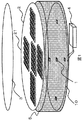
まず図1を用いて、本発明の第一実施例の構成を説明する。ここで、図1は、第一の実施例に係る照明装置の分解斜視図を示している。以下、本実施例に係る照明装置として、シーリングライトを例にして本実施例について説明する。   First, the configuration of the first embodiment of the present invention will be described with reference to FIG. Here, FIG. 1 shows an exploded perspective view of the illumination device according to the first embodiment. Hereinafter, as a lighting device according to the present embodiment, a ceiling light is taken as an example to describe the present embodiment.

図1に示されるように、本実施例に係る照明装置は、複数の光源1と、この複数の光源1が実装された光源基板10と、照明装置の照射面であって、かつ照明装置の光照射側の外装ケースである、透光性及び光拡散性を有するセード3を備えている。尚、紙面上方が本実施例に係る照明装置の光照射方向(光照射側)である。図1に示されたセードは平面状であるが、光照射側に凸を向けて湾曲された形状であってもよい。   As shown in FIG. 1, the illumination device according to the present embodiment includes a plurality of light sources 1, a light source substrate 10 on which the plurality of light sources 1 are mounted, an irradiation surface of the illumination device, and the illumination device. A shade 3 having translucency and light diffusibility, which is an exterior case on the light irradiation side, is provided. The upper side of the drawing is the light irradiation direction (light irradiation side) of the illumination device according to the present embodiment. The shade shown in FIG. 1 has a planar shape, but may have a shape curved with a convex toward the light irradiation side.

そして、本実施例では、光源1とセード3との間に、複数の光学要素21が二次元的に形成された光学部材2を配置している。この光学部材2は、例えば透明な樹脂で構成された板状の部材であり、その表面(セード3側)、裏面(光源1側)又はその両面に、例えば凸レンズの形状を為す複数の光学要素21が形成されている。   In this embodiment, an optical member 2 in which a plurality of optical elements 21 are two-dimensionally formed is disposed between the light source 1 and the shade 3. The optical member 2 is a plate-like member made of, for example, a transparent resin, and has a plurality of optical elements that form, for example, convex lenses on the front surface (the shade 3 side), the back surface (the light source 1 side), or both surfaces thereof. 21 is formed.

光源基板10及び光学部材2は、照明装置の側面周囲を覆う円筒状の外装ケースである側面カバー5に収納されて所定の位置に例えばネジやピン或いは係合部品などによって固定される。またセード3は、円筒状の側面カバー5の光照射側端部に結合或いは係合される。光源基板10の背面側には電源部4が接続されており、この電源部4からの電源が光源基板10に形成された配線パターンを通じて各光源1に供給される。   The light source substrate 10 and the optical member 2 are housed in a side cover 5 that is a cylindrical outer case that covers the periphery of the side surface of the lighting device, and fixed at predetermined positions by screws, pins, engaging parts, or the like. The shade 3 is coupled or engaged with the light irradiation side end of the cylindrical side cover 5. A power supply unit 4 is connected to the back side of the light source substrate 10, and power from the power supply unit 4 is supplied to each light source 1 through a wiring pattern formed on the light source substrate 10.

尚、本実施例に係る照明装置は、照射面が円形であるためセード3、光学部材2、光源基板10及び側面バー5の光照射側から見た形状が円形となっているが、これに限定されるものではない。これらの光照射側から見た形状を正方形等の矩形上としてもよいし、六角形などの多角形状としてもよい。また、本実施例では外装ケースを照射面側の外装ケースであるセード3と側面側の外装ケースである側面カバー5の2つで構成しているが、セード3を光照射側に凸を向けくように湾曲したものを用い、その内部に光学部材2を収納して光源基板10に結合するように構成すれば、セード3を側面カバー5と兼用することができ、その場合は側面カバー5は不要となる。   In addition, since the illumination device according to the present embodiment has a circular irradiation surface, the shape of the shade 3, the optical member 2, the light source substrate 10, and the side bar 5 viewed from the light irradiation side is circular. It is not limited. The shape viewed from the light irradiation side may be a rectangle such as a square, or may be a polygon such as a hexagon. Further, in this embodiment, the exterior case is composed of the shade 3 which is the exterior case on the irradiation surface side and the side cover 5 which is the exterior case on the side surface, but the shade 3 is convex toward the light irradiation side. If the optical member 2 is housed inside the optical member 2 and configured to be coupled to the light source substrate 10, the shade 3 can be used also as the side cover 5. In this case, the side cover 5 Is no longer necessary.

本実施例において、光源1は、例えば発光ダイオード(Light Emitting Diode, LED)であり、その光放出面に対向するように配置される光学部材2に発光のピークが向くように光束を出射する。本実施例では、LEDとして例えば白色光を出射する白色LEDを用いることができる。白色LEDは、例えば電力を受けて青色光を発光する発光チップ部分と、該発光チップからの青色光を受けて励起され、緑から赤にかけた波長領域のスペクトルを持つ光を発光する蛍光体とを有している。この蛍光体として、赤と緑の光を同時に励起して黄色に見える発光スペクトルを有する蛍光体を用いることもできる。さらに、一つのLEDにおいて、複数の発光チップを搭載した大光量タイプのLEDを利用してもよい。複数の発光チップを搭載したLEDでは、LEDの発光面(光放出面)の中心を規準にして対称となるように、発光チップを例えば矩形状、同心円状に配置することが好ましいが、配置はこれに限定されるものではない。   In the present embodiment, the light source 1 is, for example, a light emitting diode (LED), and emits a light flux so that the peak of light emission is directed to the optical member 2 disposed so as to face the light emitting surface thereof. In this embodiment, for example, a white LED that emits white light can be used as the LED. The white LED includes, for example, a light emitting chip portion that emits blue light when receiving power, a phosphor that is excited by receiving blue light from the light emitting chip, and emits light having a spectrum in a wavelength range from green to red. have. As this phosphor, a phosphor having an emission spectrum that appears to be yellow by exciting red and green light simultaneously can be used. Further, in one LED, a large light quantity type LED on which a plurality of light emitting chips are mounted may be used. In an LED equipped with a plurality of light emitting chips, it is preferable to arrange the light emitting chips in, for example, a rectangular shape or a concentric circle so that they are symmetrical with respect to the center of the light emitting surface (light emitting surface) of the LED. It is not limited to this.

また光源1には、配光の調整や光の取り出し効率を改善するためのレンズやリフレクタなどの光調節部品が備えられていてもよい。かかる光調節部品として、例えば、透過性を有する材質で成形された凸レンズや、金属蒸着されたミラーなどを用いることができる。   The light source 1 may be provided with light adjusting components such as a lens and a reflector for improving light distribution adjustment and light extraction efficiency. As such a light adjusting component, for example, a convex lens formed of a transmissive material, a metal-deposited mirror, or the like can be used.

光源基板10は、そのセード3側の面に複数の光源1が二次元的に実装されている。図1では光源基板10上に光源1が5つ実装されている例を図示しているが、必要に応じて光源の実装数を変更してもよい。光源1が光源基板10に二次元的に実装される場合、光源基板10の中心に対して、光源1を同心円状に配置してもよいし、矩形を形成するように配置されていてもよいし、放射状に配置されていてもよい。更に、光源1の配置は幾何的に対称な配置であってもよいし、千鳥配置であってもよい。光源基板10中心や周辺に光源1が追加された配置でもよく、かかる光源1の配置は、本発明を限定するものではない。   A plurality of light sources 1 are two-dimensionally mounted on the surface of the light source substrate 10 on the shade 3 side. Although FIG. 1 illustrates an example in which five light sources 1 are mounted on the light source substrate 10, the number of light sources mounted may be changed as necessary. When the light source 1 is two-dimensionally mounted on the light source substrate 10, the light source 1 may be arranged concentrically with respect to the center of the light source substrate 10, or may be arranged so as to form a rectangle. However, they may be arranged radially. Furthermore, the arrangement of the light sources 1 may be a geometrically symmetrical arrangement or a staggered arrangement. An arrangement in which the light source 1 is added at the center or the periphery of the light source substrate 10 may be used, and the arrangement of the light source 1 does not limit the present invention.

また光源基板10は、光源1の他に、電源部4からの電源に基づき光源1を駆動するための駆動電圧を生成して光源1に供給するための駆動回路(ドライバ)、配線及び/または光源1への電力供給量(電流量)を制御するための制御回路などの電子部品や電気回路が設けられている。これら電子部品や電気回路は、光源基板10の光源1の実装面とは反対側の面に設けてもよい。   In addition to the light source 1, the light source substrate 10 generates a drive voltage for driving the light source 1 based on the power supply from the power supply unit 4 and supplies it to the light source 1, wiring, and / or Electronic components such as a control circuit for controlling the power supply amount (current amount) to the light source 1 and an electric circuit are provided. These electronic components and electric circuits may be provided on the surface of the light source substrate 10 opposite to the mounting surface of the light source 1.

ここで、光源基板10の表面(セード3側の面)の光学特性は、光の吸収が少なく反射率の高い特性であることが望ましい。光学部材2は透明な材質で構成されているが、光源1から出射して光学部材2に入射した光線は、光学部材2と空気との界面で発生するフレネル反射のため、全ての光線を透過させることができない。照明装置では理想的には光源1からの光線が全て光学部材2を透過することが望ましいので、フレネル反射で透過しなかった光線を再び光学部材2へ向かって入射させることが好ましい。本実施例では、光学部材2と空気の界面で反射した光線を再び光学部材2へ向かって入射させるために、光源基板10の表面に反射性が高い材質を設けている。これは、例えば白色塗料(インク)を光源基板10の表面に塗布することで実現できる。これによって、光源基板10上の表面に反射特性を持たせ、光学部材2で反射して光源1側(光源基板10側)に戻ってきた光線を光源基板10の表面で再び光学部材2へ向かって反射させることができる。光源基板10の表面に反射特性を持たせるために、上記の例では白色塗料を光源基板10の表面に塗布したが、白色の反射シートや反射フィルムを光源基板10の表面に配置或いは積層するようにしてもよい。また光源基板10に吸収が少ない金属光沢面を露出させた構成であってもよいし、更にまた光源基板10を鏡面加工してもよい。   Here, it is desirable that the optical characteristics of the surface of the light source substrate 10 (the surface on the shade 3 side) have a high reflectance with little light absorption. The optical member 2 is made of a transparent material, but the light beam emitted from the light source 1 and incident on the optical member 2 transmits all the light beams because of Fresnel reflection generated at the interface between the optical member 2 and air. I can't let you. In the illuminating device, ideally, it is desirable that all the light rays from the light source 1 pass through the optical member 2, so that the light rays that have not been transmitted by Fresnel reflection enter the optical member 2 again. In the present embodiment, a highly reflective material is provided on the surface of the light source substrate 10 so that the light beam reflected at the interface between the optical member 2 and the air is incident again on the optical member 2. This can be realized, for example, by applying a white paint (ink) to the surface of the light source substrate 10. As a result, the surface on the light source substrate 10 has a reflection characteristic, and the light beam reflected by the optical member 2 and returning to the light source 1 side (light source substrate 10 side) is directed again toward the optical member 2 on the surface of the light source substrate 10. Can be reflected. In the above example, the white paint is applied to the surface of the light source substrate 10 in order to give the surface of the light source substrate 10 reflection characteristics. However, a white reflection sheet or reflection film is arranged or laminated on the surface of the light source substrate 10. It may be. Moreover, the structure which exposed the metal glossy surface with little absorption to the light source substrate 10 may be sufficient, and also the light source substrate 10 may be mirror-finished.

尚、光源基板10は放熱性が良いアルミなどの金属で構成されていてもよい。もし光源基板10へ供給される電力が少なく放熱性が重要視されない場合には金属以外の材質、例えばガラスエポキシ樹脂等で構成されていてもよい。   The light source substrate 10 may be made of a metal such as aluminum having good heat dissipation. If the power supplied to the light source substrate 10 is small and heat dissipation is not important, the light source substrate 10 may be made of a material other than metal, such as glass epoxy resin.

光学部材2は、例えばガラスやプラスチックなどの光透過性を有する透明材質により構成されている。かかる透明材質は、例えば、生産性に優れたプラスチックを例に挙げると、ポリカーボネート、アクリルなどを利用することができる。光学部材2を製造する方法として、たとえば、アクリルなどの透明樹脂を熱して流動性を高めて金型に流し込み、これを冷やし固めて成型する射出成形を利用することができる。このとき、光学部材2の光入射面、出射面を成形する金型の表面は研磨されていることが好ましい。   The optical member 2 is made of a transparent material having optical transparency such as glass or plastic. As the transparent material, for example, polycarbonate, acrylic, or the like can be used when a plastic having excellent productivity is taken as an example. As a method of manufacturing the optical member 2, for example, injection molding can be used in which a transparent resin such as acrylic is heated to increase the fluidity and poured into a mold, which is cooled and solidified. At this time, it is preferable that the surface of the mold for molding the light incident surface and the light emitting surface of the optical member 2 is polished.

光学部材2に形成される光学要素21は、光源1からの光線を屈折または反射させる形状をしている。その形状は、典型的には凸レンズ形状である。また光学要素21の形状として、たとえば、球面、平面、またはその他の種類の曲面で構成されていてもよい。かかる光学要素21は、図1に示されるように、1つの光源1に対して複数個(図1の例では30個)光学部材2に設けられている。すなわち複数の光源1のそれぞれに対して複数の光学要素21群が対応して設けられている。   The optical element 21 formed on the optical member 2 has a shape that refracts or reflects light from the light source 1. The shape is typically a convex lens shape. Moreover, as a shape of the optical element 21, you may be comprised by the spherical surface, the plane, or another kind of curved surface, for example. As shown in FIG. 1, a plurality of optical elements 21 (30 in the example of FIG. 1) are provided on the optical member 2 for one light source 1. That is, a plurality of optical element groups 21 are provided corresponding to each of the plurality of light sources 1.

光学要素21を製造する方法として、例えば金型による射出成型がある。光学部材2を射出成型する金型に光学要素21の形状を彫り込んでおけば、光学部材2の表面に一体で光学要素21を成型する事ができる。この製造方法は光学部材2と光学要素21を一体成型できるため、製造工程が比較的少なくなり製造コストを抑えることが可能となる。   As a method for manufacturing the optical element 21, there is, for example, injection molding using a mold. If the shape of the optical element 21 is engraved in a mold for injection molding the optical member 2, the optical element 21 can be integrally molded on the surface of the optical member 2. In this manufacturing method, since the optical member 2 and the optical element 21 can be integrally formed, the manufacturing process is relatively reduced, and the manufacturing cost can be suppressed.

その他の製造方法として、光学要素21を光学部材2とは別のシート状の部材として製造し、光学部材2の表面又は裏面或いはその両方に張り付ける方法がある。光学要素21が複雑な形状である場合、金型による射出成型では成型が困難な場合がある。射出成型では、成型品の厚みが大きい場合、冷えて固まる際に収縮する。細かい形状は前記の収縮によって形状が歪んでしまう問題がある。従って、光学要素21を細かく複雑な形状とする場合には、厚さが薄いシートの表面に光学要素21を形成する方法が有効である。光学要素21を形成したシートは、形状保持のため光学部材2に貼り付ける必要がある。貼り付けに利用する接着剤は透明で、その屈折率は光学部材2と光学要素21の中間の値であることが望ましい。それは、異なる媒質間の屈折率の差は、両者の界面で反射光が発生する原因となるためである。すなわち、上記の構成であれば光学部材21と光学部材2との間に挟まれる接着剤の界面で発生する反射光を抑えることができ、透過率を高めることができる。このため、光源1から出射された光束を効率的に光学部材2と光学部材21を透過させ、セード3に入射される光量を増加させることができる。   As another manufacturing method, there is a method in which the optical element 21 is manufactured as a sheet-like member different from the optical member 2 and attached to the front surface, the back surface, or both of the optical member 2. When the optical element 21 has a complicated shape, molding may be difficult by injection molding using a mold. In injection molding, when the thickness of a molded product is large, it shrinks when it cools and hardens. The fine shape has a problem that the shape is distorted by the contraction. Therefore, in the case where the optical element 21 has a fine and complicated shape, a method of forming the optical element 21 on the surface of a thin sheet is effective. The sheet on which the optical element 21 is formed needs to be attached to the optical member 2 in order to maintain the shape. The adhesive used for pasting is transparent, and its refractive index is preferably an intermediate value between the optical member 2 and the optical element 21. This is because the difference in refractive index between different media causes reflected light to be generated at the interface between the two media. That is, if it is said structure, the reflected light which generate | occur | produces in the interface of the adhesive agent pinched | interposed between the optical member 21 and the optical member 2 can be suppressed, and the transmittance | permeability can be raised. For this reason, the light beam emitted from the light source 1 can be efficiently transmitted through the optical member 2 and the optical member 21, and the amount of light incident on the shade 3 can be increased.

上記光学部材2に形成された光学要素21によって、光源1から出射した光線を屈折もしくは反射されてセード3に入射される。この光学部材2に形成された光学要素21の光学的作用について図2を参照して更に説明する。   The light emitted from the light source 1 is refracted or reflected by the optical element 21 formed on the optical member 2 and enters the shade 3. The optical action of the optical element 21 formed on the optical member 2 will be further described with reference to FIG.

図2は本実施例に係る照明装置の照射面と直交する断面を示している。この例では、1つの光源1に対して3つの光学要素21a〜21cが光学部材21に形成されており、各光学要素21a〜21cは、それぞれ、光源1(光源基板10)側に凸を向けた球面の入射面211とセード3側に凸を向けた球面の出射面212含む球面両凸レンズ形状を有しているものとする。尚、図2の例では光学要素21を3つとしているが、勿論これとは異なる数であってもよく、光源1の数より多ければよい。   FIG. 2 shows a cross section orthogonal to the irradiation surface of the illumination apparatus according to the present embodiment. In this example, three optical elements 21 a to 21 c are formed on the optical member 21 for one light source 1, and each optical element 21 a to 21 c is convex toward the light source 1 (light source substrate 10) side. It is assumed that it has a spherical biconvex lens shape including a spherical incident surface 211 and a spherical exit surface 212 convex toward the shade 3 side. In the example of FIG. 2, the number of the optical elements 21 is three, but it is needless to say that the number of optical elements 21 may be different from that of the light source 1.

図2に示された例において、光源1から出射した光束は、光学要素21a、21bおよび21cに入射した光束ごとに光路が分離される。具体的には、光学要素21aの入射面211に入射した光線は、その表面で屈折される。光学要素21aの入射面211によって屈折された光線は、光学要素21aの出射面で再び屈折させられる。その結果、光源1から出射した光束のうち、光学要素21aに入射した光束はセード上のある領域(光学要素21aのほぼ直上)に向かって出射される。同様に、光源1から出射した光束のうち光学要素21bに入射した光束は、光学要素21aを通過した光束が到達したセード3の領域とは別の領域(光学要素21bのほぼ直上)を照明し、光学要素21cに入射した光束は、光学要素21a及び21bを通過した光束が到達したセード3の領域とはまた別の領域(光学要素21cのほぼ直上)を照明する。当然、各学要素21a〜21cによってセード3上に照射される光束の範囲は、部分的に互いに重複していてもよい。   In the example shown in FIG. 2, the optical path of the light beam emitted from the light source 1 is separated for each light beam incident on the optical elements 21a, 21b, and 21c. Specifically, the light beam incident on the incident surface 211 of the optical element 21a is refracted on the surface. The light beam refracted by the incident surface 211 of the optical element 21a is refracted again by the output surface of the optical element 21a. As a result, of the light beams emitted from the light source 1, the light beam incident on the optical element 21a is emitted toward a certain area on the shade (almost directly above the optical element 21a). Similarly, the light beam incident on the optical element 21b out of the light beam emitted from the light source 1 illuminates a region (almost directly above the optical element 21b) different from the region of the shade 3 where the light beam having passed through the optical element 21a has reached. The light beam incident on the optical element 21c illuminates a region (substantially directly above the optical element 21c) different from the region of the shade 3 where the light beams that have passed through the optical elements 21a and 21b have reached. Naturally, the ranges of the light beams irradiated onto the shade 3 by the respective academic elements 21a to 21c may partially overlap each other.

かかる光学要素21a〜21cの光学的作用によれば、光源1から出射した光束は、光学部材2に設けられた光学要素21a〜21cによって分離され、それぞれの光学要素21があたかも複数の光源であるようにセード3を照明する。すなわち、各光学要素21を擬似的な光源として機能させることができる。セード3を均一に照射するためには、セード3と光源1との距離に対して光源を密に配置することが有効であるが、本実施例の構成であれば、各光源1からの出射光束を、該各光源のそれぞれに対応して光学部材2に設けられた、光源1の間隔よりも密に配置された複数の光学要素21によって複数の光束に分離してセード3を照明するので、セード3上に照射される各光学要素21からの出射光束間の間隔(距離)を光源基板10上に配置された光源1間の間隔(距離)よりも短くすることができる。その結果、光源1とセード3の距離が一定であるとき、光学部材2を利用せずに光源1の光束を直接的にセード3に照射するときに比べて、セード3を均一に照射できる。   According to the optical action of the optical elements 21a to 21c, the light beam emitted from the light source 1 is separated by the optical elements 21a to 21c provided on the optical member 2, and each optical element 21 is as if it were a plurality of light sources. Illuminate the shade 3 as follows. That is, each optical element 21 can function as a pseudo light source. In order to uniformly irradiate the shade 3, it is effective to arrange the light sources densely with respect to the distance between the shade 3 and the light source 1. Since the light beam is separated into a plurality of light beams by a plurality of optical elements 21 disposed on the optical member 2 corresponding to each of the light sources and arranged more densely than the interval between the light sources 1, the shade 3 is illuminated. The interval (distance) between the emitted light beams from the optical elements 21 irradiated onto the shade 3 can be made shorter than the interval (distance) between the light sources 1 arranged on the light source substrate 10. As a result, when the distance between the light source 1 and the shade 3 is constant, the shade 3 can be irradiated more uniformly than when the light beam from the light source 1 is directly irradiated onto the shade 3 without using the optical member 2.

ここで、光学部材2に設けられた光学要素21の形状の一例について図3及び図4を参照して説明する。図3は光学要素21の形状の一例を示すものであって、1つの光学要素21の、光学要素21の中心を含み且つ光学部材2の面と直交する断面の拡大図を示している。図4は、光学要素21の形状の他の例を示すものであって、1つの光学要素21の、光学要素21の中心を含み且つ光学部材2の面と直交する断面の拡大図を示している。   Here, an example of the shape of the optical element 21 provided in the optical member 2 will be described with reference to FIGS. 3 and 4. FIG. 3 shows an example of the shape of the optical element 21, and shows an enlarged view of a cross section of one optical element 21 including the center of the optical element 21 and perpendicular to the surface of the optical member 2. FIG. 4 shows another example of the shape of the optical element 21, and shows an enlarged view of a cross section of one optical element 21 including the center of the optical element 21 and perpendicular to the surface of the optical member 2. Yes.

図3及び図4に示された光学要素21は、それぞれ、光源1(光源基板10)側に凸を向いた、光源1からの光が入射される入射面211と、セード4側に凸を向いた、光を出射する出射面212とを備えており、光の入射側及び出射側の両方に凸を向けた両凸形状の正レンズである。ここで、入射面211の中心と出射面212の中心は、互いに一致しているものとする。換言すれば、図3及び図4に示された光学要素21は、それぞれ、入射面211を有する半円形状の入射側レンズと出射面212を有する半円形状の出射側レンズから構成され、入射側レンズの光軸と出射側レンズの光軸とが互いに一致している。   The optical elements 21 shown in FIG. 3 and FIG. 4 are respectively convex toward the light source 1 (light source substrate 10) and are incident toward the incident surface 211 on which light from the light source 1 is incident and convex toward the shade 4 side. This is a biconvex positive lens that has a light exit surface 212 that emits light and has convex faces on both the light incident side and the light exit side. Here, it is assumed that the center of the entrance surface 211 and the center of the exit surface 212 coincide with each other. In other words, each of the optical elements 21 shown in FIGS. 3 and 4 is composed of a semicircular incident side lens having an incident surface 211 and a semicircular exit side lens having an output surface 212. The optical axis of the side lens and the optical axis of the exit side lens coincide with each other.

そして図3に示される光学要素21は、図示されるように、入射面211の焦点が光学要素21の出射面212に略一致するように構成されている。かかる構成であれば、入射面211に入射した光束のうち出射面212に入射する光束が増加するため、通過率が高くなり光学部材2の通過率を改善することができる。   The optical element 21 shown in FIG. 3 is configured such that the focal point of the incident surface 211 substantially coincides with the exit surface 212 of the optical element 21 as shown. With such a configuration, the luminous flux incident on the exit surface 212 out of the luminous flux incident on the incident surface 211 increases, so that the transmission rate is increased and the transmission rate of the optical member 2 can be improved.

このとき、入射面211(の径)が十分に小さく、入射面211の大きさに対して光源1と光学要素21の距離が十分に遠い条件を想定すると、入射面211に入射する光束は略平行光となる。光学要素21の入射面211に入射した平行光は、入射面211の焦点に一点で収束する。図3に示された例では、入射面211の焦点は出射面212に略一致させているので、出射面212において光源1からの出射光束を収束させ、通過率(光学要素21に入射される光束に対する出射光束の比)を高くすることが可能となる。ところが、実際には光源1が有限の大きさを持っているため、入射面211に入射する光束は完全な平行光束ではなく、出射面212上では有限の大きさに収束している。また、光学要素21の大きさが光源1と光学要素21との距離に比べて十分に小さくない場合、光学要素21には、ある角度で発散した光束として入射するため、光学要素21の出射面212上で略収束した光源1の像がぼけてしまう傾向にある。従って、十分な通過率を確保するためには、出射面212のサイズ(径)が、入射面211が光源像を結像するサイズよりも大きいことが望ましい。   At this time, assuming that the incident surface 211 (the diameter thereof) is sufficiently small and the distance between the light source 1 and the optical element 21 is sufficiently large with respect to the size of the incident surface 211, the light beam incident on the incident surface 211 is approximately. It becomes parallel light. The parallel light incident on the incident surface 211 of the optical element 21 converges at one point on the focal point of the incident surface 211. In the example shown in FIG. 3, since the focal point of the incident surface 211 is substantially coincident with the emission surface 212, the emitted light beam from the light source 1 is converged on the emission surface 212, and the pass rate (enters the optical element 21). The ratio of the emitted light beam to the light beam can be increased. However, since the light source 1 actually has a finite size, the light beam incident on the incident surface 211 is not a perfect parallel light beam but converges to a finite size on the output surface 212. In addition, when the size of the optical element 21 is not sufficiently small compared to the distance between the light source 1 and the optical element 21, the optical element 21 is incident on the optical element 21 as a divergent light beam. There is a tendency that the image of the light source 1 that has substantially converged on 212 is blurred. Therefore, in order to ensure a sufficient passing rate, it is desirable that the size (diameter) of the exit surface 212 is larger than the size at which the entrance surface 211 forms a light source image.

また、図4に示される光学要素21の別の例では、図示されるように、出射面212の焦点を入射面211に略一致するように構成されている。この図4に示された光学要素21の別の例の光学的作用を以下に説明する。   Further, in another example of the optical element 21 shown in FIG. 4, the focal point of the exit surface 212 is configured to substantially coincide with the entrance surface 211 as illustrated. The optical operation of another example of the optical element 21 shown in FIG. 4 will be described below.

光源1から出射した光束は、光学要素21の入射面211に到達するまでの間に発散しながら伝播するため、入射面211上における光源1からの光束によって形成される照度分布は、比較的均一となる。この光束は、図4の実線及び点線に示されるように光学要素21の内部を通過して出射面212から出射される。   Since the light beam emitted from the light source 1 propagates while diverging before reaching the incident surface 211 of the optical element 21, the illuminance distribution formed by the light beam from the light source 1 on the incident surface 211 is relatively uniform. It becomes. This light beam passes through the inside of the optical element 21 as shown by the solid line and the dotted line in FIG.

ここで、出射面の焦点を入射面に一致させた構成のレンズは、出射面の焦点上の空間的な照度分布に応じて出射光の配光分布を形成する機能を有する。従って、本例のように出射面212の焦点を入射面212に一致させれば、上述のように入射面211上の照度分布はほぼ均一であるため、出射面212からの出射光は略均一な配光分布を持つようになる。このとき、光学要素21からの出射光束の強度は、出射角(出射方向)に依存せずにほぼ一定となる。その結果、光学要素21を通して光源1が見える範囲であれば、方向によらず光学要素21が発光しているように見えるので、光源1が密に配置されていると見ることができる。従って、本例に係る光学要素21によれば、光源1からの光をセード3上で照度分布が均一になるように照射することができ、セード3上の照度分布を改善しながら通過率が高い光学系を提供できる。   Here, the lens having a configuration in which the focal point of the emission surface coincides with the incident surface has a function of forming a light distribution of the emitted light according to the spatial illuminance distribution on the focal point of the emission surface. Therefore, if the focal point of the exit surface 212 coincides with the entrance surface 212 as in this example, the illuminance distribution on the entrance surface 211 is substantially uniform as described above, and thus the exit light from the exit surface 212 is substantially uniform. Have a good light distribution. At this time, the intensity of the emitted light beam from the optical element 21 becomes substantially constant without depending on the emission angle (outgoing direction). As a result, if the light source 1 can be seen through the optical element 21, the optical element 21 appears to emit light regardless of the direction, so that it can be seen that the light sources 1 are densely arranged. Therefore, according to the optical element 21 according to the present example, the light from the light source 1 can be irradiated so that the illuminance distribution on the shade 3 is uniform, and the passage rate is improved while improving the illuminance distribution on the shade 3. A high optical system can be provided.

このように、本実施例によれば、各光源1に対して光源1の間隔よりも密に配置された複数の光源を設け、これを介して光源1からの光をセードに3照射しているので、光学部材2を光照射側から見たときに、複数の光源が密に配置されて光を照射しているように見える。このため、実際の光源1の数を増加させたり、光源1とセード3間の距離を長くしたり、また照明光の空間的な輝度均一性を高めるためにセード3の拡散度を高めたりなくても空間的な輝度均一性を向上させることができる。このため、本実施例によれば、光源1の数を増加させず、また照明装置の厚さを厚くすること無く、またセード3の拡散度を高めることなく輝度均一性の高い照明装置を提供することができる。一般的に、セード3の拡散度を下げるとセード3の透過率を高くすることができるため、照明装置の発光効率を高くすることができる。   Thus, according to the present embodiment, a plurality of light sources arranged more densely than the interval between the light sources 1 are provided for each light source 1, and three shades of light from the light source 1 are irradiated to the shades through this. Therefore, when the optical member 2 is viewed from the light irradiation side, it appears that a plurality of light sources are arranged densely and irradiate light. For this reason, the number of actual light sources 1 is not increased, the distance between the light sources 1 and the shade 3 is increased, and the diffusivity of the shade 3 is not increased in order to improve the spatial luminance uniformity of the illumination light. However, spatial brightness uniformity can be improved. For this reason, according to the present embodiment, an illumination device with high luminance uniformity is provided without increasing the number of light sources 1, without increasing the thickness of the illumination device, and without increasing the diffusivity of the shade 3. can do. Generally, when the diffusivity of the shade 3 is lowered, the transmittance of the shade 3 can be increased, so that the luminous efficiency of the lighting device can be increased.

従って、本実施例によれば、コストの上昇を抑え厚さを薄くしつつも、輝度均一性が高くかつ明るい照明光を照射することが可能な照明装置を提供することができる。   Therefore, according to the present embodiment, it is possible to provide an illuminating device that can irradiate bright illumination light with high brightness uniformity while suppressing an increase in cost and reducing the thickness.

尚、本実施例では照明装置としてシーリングライトを例にして説明したが、他の照明装置にも適用可能であることは言うまでもない。また、本実施例では1つの光源1に対して複数の光学要素21を設けたが、複数の光源を有する光源群(例えば近接して配置された2〜3つの光源)に対して該光源群の光源数よりも多い複数の光学要素21を設けるようにしてもよい。   In this embodiment, the ceiling light is described as an example of the lighting device, but it goes without saying that the present invention can be applied to other lighting devices. In the present embodiment, a plurality of optical elements 21 are provided for one light source 1, but the light source group is provided for a light source group having a plurality of light sources (for example, two to three light sources arranged close to each other). A plurality of optical elements 21 larger than the number of the light sources may be provided.

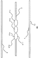
次に、図5及び図6を用いて本発明の第二実施例の一構成例を説明する。図5は、第二実施例に係る光学系の、光源1の中心と光学要素21bの中心を含み且つ光学部材21の面と直交する面の断面図を示している。図示されるように、本実施例では、光学要素21a及び21cの出射面212の中心が、光学要素21a及び21cの入射面211の中心よりも光源1に対して外側に位置している
本実施例の光学的作用の説明の前に、図6を参照して、第一実施例のように光学要素21a入射面211の中心と出射面212の中心が一致している場合の光学的作用を説明する。簡単のため、入射面211が十分に小さく、入射面211の大きさに対して光源1との距離が十分に遠い条件を想定する。この条件下では、光源1から入射面211に入射する光束は略平行光となる。光学要素21に対して入射面211から入射した平行光は、入射面211の焦点に一点で収束する。図6の例では、入射面211の焦点が出射面212に略一致しているものとする。
Next, a configuration example of the second embodiment of the present invention will be described with reference to FIGS. FIG. 5 is a cross-sectional view of a surface of the optical system according to the second embodiment that includes the center of the light source 1 and the center of the optical element 21 b and is orthogonal to the surface of the optical member 21. As shown in the figure, in the present embodiment, the centers of the exit surfaces 212 of the optical elements 21a and 21c are located outside the light source 1 with respect to the centers of the entrance surfaces 211 of the optical elements 21a and 21c. Before the description of the optical action of the example, referring to FIG. 6, the optical action when the center of the incident surface 211 of the optical element 21a and the center of the outgoing face 212 are coincident as in the first embodiment. explain. For simplicity, it is assumed that the incident surface 211 is sufficiently small and the distance from the light source 1 is sufficiently far from the size of the incident surface 211. Under this condition, the light beam incident on the incident surface 211 from the light source 1 becomes substantially parallel light. The parallel light incident on the optical element 21 from the incident surface 211 converges at one point on the focal point of the incident surface 211. In the example of FIG. 6, it is assumed that the focal point of the incident surface 211 substantially coincides with the output surface 212.

このとき、光源1から光学要素21の入射面211に入射した光束は、入射面211で屈折させられて出射面212に収まる範囲に収束されるが、この光束は様々な角度を有する光線を含んでいる。このため、出射面212の法線に対して臨界角度よりも大きな角度で入射する光線は、出射面212で全反射して出射面212を通過することができず、戻り光となって入射面211に向かう。かかる戻り光の発生は、光学要素21又は光学部材2の透過率を低下させる要因となる。   At this time, the light beam incident on the incident surface 211 of the optical element 21 from the light source 1 is refracted by the incident surface 211 and converged in a range that fits on the output surface 212. However, this light beam includes light beams having various angles. It is out. For this reason, a light ray incident at an angle larger than the critical angle with respect to the normal line of the emission surface 212 cannot be totally reflected by the emission surface 212 and pass through the emission surface 212, and becomes return light as an incident surface. Head to 211. The generation of such return light becomes a factor that reduces the transmittance of the optical element 21 or the optical member 2.

これに対し本実施例に係る照明装置は、図5に示されるように、光学要素21a〜21cのそれぞれはセード3側に凸を向けた出射面212と光源1側に凸を向けた入射面211を持つ両凸レンズ形状を有しているが、、光源1の光軸上に位置する光学要素21bの周囲(つまり光学要素21bよりも外側)に位置する光学要素21a及び21cの出射面212の中心が、光源1に対して光学要素21a及び21cの入射面211の中心よりも外側に位置している。すなわち、本実施例は、光学要素21a及び21cのそれぞれの出射面212の中心を、入射面211の中心よりも外側に位置するように、出射面212の中心と入射面211の中心をずらした構成となっている。このような構成によって、入射面211を通過して入射面211の焦点に向かうように収束している光束は、図示されるように出射面212に対して深い角度で入射させることができるようになる。このため、出射面212で全反射して入射面211側に向かう戻り光を抑えることができ、光学部材2の通過率を高くすることができる。   On the other hand, in the illumination device according to the present embodiment, as shown in FIG. 5, each of the optical elements 21 a to 21 c has an exit surface 212 that is convex toward the shade 3 side and an incident surface that is convex toward the light source 1 side. Although it has a biconvex lens shape having 211, the optical elements 21a and 21c located on the periphery of the optical element 21b located on the optical axis of the light source 1 (that is, outside the optical element 21b) The center is located outside the center of the incident surface 211 of the optical elements 21 a and 21 c with respect to the light source 1. That is, in the present embodiment, the center of the exit surface 212 and the center of the entrance surface 211 are shifted so that the center of the exit surface 212 of each of the optical elements 21a and 21c is positioned outside the center of the entrance surface 211. It has a configuration. With such a configuration, the light beam that has converged so as to pass through the incident surface 211 toward the focal point of the incident surface 211 can be incident on the exit surface 212 at a deep angle as illustrated. Become. For this reason, it is possible to suppress the return light that is totally reflected by the exit surface 212 and travels toward the entrance surface 211, and the passing rate of the optical member 2 can be increased.

また、本実施例の構成において第一実施例のように出射面212の焦点を入射面211に略一致するように光学要素21を構成すれば、上記第一実施例で説明したように入射面211上の照度分布は均一であるため、出射面212から均一な配光分布の出射光を得ることができる。その結果、セード3上では照度分布が均一になるように照明される。   Further, in the configuration of the present embodiment, if the optical element 21 is configured so that the focal point of the emission surface 212 substantially coincides with the incident surface 211 as in the first embodiment, the incident surface as described in the first embodiment. Since the illuminance distribution on 211 is uniform, outgoing light having a uniform light distribution can be obtained from the outgoing surface 212. As a result, illumination is performed on the shade 3 so that the illuminance distribution is uniform.

このように、本実施例の構成によれば、入射面211からの入射光が出射面212で全反射されることが抑制されるため、セード3上の照度分布を改善しながら発光効率を高めることができる。   As described above, according to the configuration of this embodiment, since the incident light from the incident surface 211 is suppressed from being totally reflected by the output surface 212, the luminous efficiency is improved while improving the illuminance distribution on the shade 3. be able to.

次に、図7を用いて本発明の第三実施例の一構成例を説明する。図7は、第三実施例に係る光学系及び光学部材2の、光源1の中心と光学部材2の中心を含み且つ光学部材2の面と直交する面の断面図を示している。   Next, a configuration example of the third embodiment of the present invention will be described with reference to FIG. FIG. 7 shows a cross-sectional view of the surface of the optical system and the optical member 2 according to the third embodiment that includes the center of the light source 1 and the center of the optical member 2 and is orthogonal to the surface of the optical member 2.

図4に示されるように、本実施例に係る照明装置は、光学部材2に形成する光学要素21として、両凸レンズに代えてフレネルレンズの一部を形成している。より詳細には、本実施例は、図7に示されるように光学部材2の入射面(光源1側)に、光源1側に凸を向けた入射面フレネルレンズ214を形成し、光学部材2の出射面(セード4側)にセード4側に凸を向けた出射面フレネルレンズ215を形成している。入射面フレネルレンズ214及び出射面フレネルレンズ215は、複数の光源1のそれぞれに対応して設けられている。すなわち、入射面フレネルレンズ214及び出射面フレネルレンズ215は、光学部材2の面状に各光源1に対応させて複数設けられている。ここで、入射側フレネルレンズ214及び/または出射側フレネルレンズ215の焦点距離は、光学部材2上の位置に応じて変化させている。   As shown in FIG. 4, the illumination device according to the present embodiment forms a part of a Fresnel lens as an optical element 21 formed on the optical member 2 instead of a biconvex lens. More specifically, in this embodiment, as shown in FIG. 7, an incident surface Fresnel lens 214 having a convex surface directed toward the light source 1 is formed on the incident surface (light source 1 side) of the optical member 2. The exit surface Fresnel lens 215 is formed on the exit surface (side of the shade 4) with the convex toward the shade 4 side. The entrance surface Fresnel lens 214 and the exit surface Fresnel lens 215 are provided corresponding to each of the plurality of light sources 1. That is, a plurality of incident surface Fresnel lenses 214 and output surface Fresnel lenses 215 are provided in correspondence with each light source 1 on the surface of the optical member 2. Here, the focal length of the entrance-side Fresnel lens 214 and / or the exit-side Fresnel lens 215 is changed according to the position on the optical member 2.

かかる本実施例の構成によれば、光源1から出射して光学部材2に入射される光束に対し、広い領域で光学部材2での入射位置に応じた所望の光学特性を実現することができる。例えば、光源1から出射した光束のうち、光源1の光軸に近い方向の光線に対しては入射側フレネルレンズ214及び/または出射側フレネルレンズ215レンズのパワーを弱く、光源1の光軸から離れる方向に向かう光線に対しては入射側フレネルレンズ214及び/または出射側フレネルレンズ215レンズのパワーを強める構成とすることができる。すなわち、本実施例の構成によれば、光源1の出射光束を有効にセード3上に照射することできるので、効率を高めつつセード3上に光を均一に照射することが可能となる。   According to the configuration of the present embodiment, desired optical characteristics corresponding to the incident position on the optical member 2 can be realized in a wide area with respect to the light beam emitted from the light source 1 and incident on the optical member 2. . For example, the power of the incident-side Fresnel lens 214 and / or the emission-side Fresnel lens 215 lens is weak for the light beam emitted from the light source 1 in the direction close to the optical axis of the light source 1, and from the optical axis of the light source 1. For light rays traveling in the direction away from the light source, the power of the incident-side Fresnel lens 214 and / or the output-side Fresnel lens 215 can be increased. That is, according to the configuration of the present embodiment, the emitted light beam of the light source 1 can be effectively irradiated onto the shade 3, so that the light can be uniformly irradiated onto the shade 3 while improving the efficiency.

入射側フレネルレンズ214の焦点を、例えば図示されるように光源1の光放出面に位置させるように構成してもよい。この構成において、光源1から出射した光束は、入射側フレネルレンズ214に入射して屈折され、出射側フレネルレンズ215で再度屈折されて出射するが、出射側フレネルレンズ215から出射した光束は、光源1の光軸に対して略平行に出射する。出射側フレネルレンズ215から光源1の光軸と平行な方向に光束を出射させれば、セード3が光源1の光軸方向(光学要素2或いは光源基板2と直交する方向)に移動したとしても、出射側フレネルレンズ215からの出射光が照射されるセード3上の領域での照度分布は、変化が生じにくい。   You may comprise so that the focus of the incident side Fresnel lens 214 may be located in the light emission surface of the light source 1, for example so that it may show in figure. In this configuration, the light beam emitted from the light source 1 enters the incident-side Fresnel lens 214 and is refracted, and is refracted and emitted again by the output-side Fresnel lens 215. The light is emitted substantially parallel to one optical axis. Even if the shade 3 is moved in the optical axis direction of the light source 1 (the direction perpendicular to the optical element 2 or the light source substrate 2) if the light beam is emitted from the emission-side Fresnel lens 215 in a direction parallel to the optical axis of the light source 1. The illuminance distribution in the region on the shade 3 where the outgoing light from the outgoing-side Fresnel lens 215 is irradiated hardly changes.

すなわち、入射側フレネルレンズ214の焦点を光源1の光放出面に位置させるように構成すれば、光源1の出射光束を有効に利用しつつ、セード3の取り付け誤差に起因する光学性能の変動を抑えることができ、組み立ての許容誤差を緩和した製造性が高い照明装置及び光学系を提供できる。   That is, if the focal point of the incident-side Fresnel lens 214 is configured to be positioned on the light emitting surface of the light source 1, the optical performance fluctuation caused by the attachment error of the shade 3 can be effectively utilized while effectively using the emitted light beam of the light source 1. It is possible to provide an illuminating device and an optical system that can be suppressed and have high manufacturability with reduced assembly tolerances.

尚、図7では、光学部材2に形成されるフレネルレンズとして、光源1側及びセード3側ともに凸面形状をしているものを図示しているが、一方が平面または凹面形状のいずれかを組み合わせた構成であってもよい。   In FIG. 7, the Fresnel lens formed on the optical member 2 is shown as having a convex shape on both the light source 1 side and the shade 3 side, but one of them is a combination of either a flat surface or a concave surface shape. It may be a configuration.

次に、図8〜10を用いて本発明の第四実施例の一構成例を説明する。この第四実施例は、光学部材2における光学要素の二次元的な配列の実施例である。   Next, a configuration example of the fourth embodiment of the present invention will be described with reference to FIGS. The fourth embodiment is an embodiment of a two-dimensional arrangement of optical elements in the optical member 2.

図8は、本実施例に係る光学部材2における光学要素の第1の配列例を示すものであって、光学部材2を光照射側から見た正面図を示している。   FIG. 8 shows a first arrangement example of the optical elements in the optical member 2 according to the present embodiment, and shows a front view of the optical member 2 as viewed from the light irradiation side.

図8に示されるように、第1の配列例は、複数の光源1のそれぞれに対応する位置を中心とした光学部材2上の所定の領域に、光学要素21(例えば第一実施例の両凸レンズ)が各光源1と対応する位置を基準にして放射状に配置したものである。すなわち、1つの光源1と対応する位置を基準に複数の円形の光学要素21が放射状に配置された所定の領域が、各光源1に対応して光学部材2上に複数設けられている。尚、本実施例において、光学要素21の光照射側から見た形状は円形である。   As shown in FIG. 8, in the first arrangement example, an optical element 21 (for example, both of the first embodiment) is placed in a predetermined region on the optical member 2 with the position corresponding to each of the plurality of light sources 1 as the center. Convex lenses) are arranged radially with reference to positions corresponding to the respective light sources 1. That is, a plurality of predetermined regions in which a plurality of circular optical elements 21 are radially arranged with respect to a position corresponding to one light source 1 are provided on the optical member 2 corresponding to each light source 1. In this embodiment, the shape of the optical element 21 viewed from the light irradiation side is a circle.

光源1が光を照射できる領域に対してセード3が広い場合、複数の光源1を用いて広域を照射するが、本実施例の構成であれば、第一実施例等でも説明したように、セード4の広い領域を照射することができる。そして第1の配列例では、複数の光源1のそれぞれに対応し複数の光学要素21を、1つの光源1と対応する位置を基準にして放射状に設けることで、光学要素21の光学特性の幾何的な対称性を維持することが可能である。尚、本例では各光源1に対応する複数の光学要素の個数はそれぞれ同じとしているが、例えば光学部材2の中心に位置する光源1に対応する光学要素の個数を、外側に位置する光源1に対応する光学要素の個数よりも多くしてもよい。照明装置照射面の周囲の輝度均一性を向上させたい場合は、逆に光学部材2の外側に位置する光源1に対応する光学要素の個数を、中心に位置する光源1に対応する光学要素の個数よりも多くしてもよい。   When the shade 3 is wide with respect to the region where the light source 1 can irradiate light, a plurality of light sources 1 are used to irradiate a wide area. However, if the configuration of this embodiment is used, as described in the first embodiment, etc. A wide area of the shade 4 can be irradiated. In the first arrangement example, a plurality of optical elements 21 corresponding to each of the plurality of light sources 1 are provided radially with respect to a position corresponding to one light source 1, so that the geometrical characteristics of the optical characteristics of the optical elements 21 are obtained. It is possible to maintain a general symmetry. In this example, the number of optical elements corresponding to each light source 1 is the same. For example, the number of optical elements corresponding to the light source 1 located at the center of the optical member 2 is set to the light source 1 located outside. The number may be larger than the number of optical elements corresponding to. When it is desired to improve the luminance uniformity around the illumination device irradiation surface, conversely, the number of optical elements corresponding to the light source 1 located outside the optical member 2 is set to the number of optical elements corresponding to the light source 1 located in the center. It may be more than the number.

すなわち、本実施例の構成であれば、複数の光源1を用いながら、光学部材2の透過率を高めてセード3上を均一に照射する光学系を提供できる。   That is, with the configuration of the present embodiment, an optical system that uniformly irradiates the shade 3 by increasing the transmittance of the optical member 2 while using the plurality of light sources 1 can be provided.

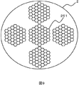
次に、図9を用いて本実施例に係る光学要素の第2の配列例を説明する。図9は、本実施例に係る光学部材2における光学要素の第2の配列例を示すものであって、光学部材2を光照射側から見た正面図を示している。   Next, a second arrangement example of optical elements according to the present embodiment will be described with reference to FIG. FIG. 9 shows a second arrangement example of the optical elements in the optical member 2 according to the present embodiment, and shows a front view of the optical member 2 as viewed from the light irradiation side.

図9に示されるように、第1の配列例は、複数の光源1のそれぞれに対応する位置を中心とした光学部材2上の所定の領域に、各光源1と対応する位置を中心として複数の多角形状(図9では六角形状)の光学要素251を互いが接触するように(光学要素251間に隙間が生じないように)敷き詰めて配置している。このとき、1つの所定領域に配置された光学要素251群は、光源1の位置に対応する(光源1の光軸上にある)光学要素251の中心とそれに隣接する光学要素251の中心を通る光学部材2の面状の直線を基準に対称に配列されている。すなわち、1つの光源1と対応する複数の六角形状の光学要素21がある直線を基準に対称に配置された所定の領域が、各光源1に対応して光学部材2上に複数設けられている。六角形状の光学要素21は、その中心を通り且つ光学部材の面と直交する断面が図3等に示されるように両凸のレンズ形状を為しているものとする。   As shown in FIG. 9, the first arrangement example includes a plurality of areas around the positions corresponding to the light sources 1 in a predetermined area on the optical member 2 centered on the positions corresponding to the plurality of light sources 1. The optical elements 251 having a polygonal shape (hexagonal shape in FIG. 9) are arranged so as to be in contact with each other (so that no gap is generated between the optical elements 251). At this time, the group of optical elements 251 arranged in one predetermined region passes through the center of the optical element 251 corresponding to the position of the light source 1 (on the optical axis of the light source 1) and the center of the optical element 251 adjacent thereto. The optical members 2 are arranged symmetrically with respect to the planar straight line. That is, a plurality of predetermined regions arranged symmetrically with respect to a straight line with a plurality of hexagonal optical elements 21 corresponding to one light source 1 are provided on the optical member 2 corresponding to each light source 1. . It is assumed that the hexagonal optical element 21 has a biconvex lens shape as shown in FIG. 3 and the like, with a cross section passing through the center thereof and orthogonal to the surface of the optical member.

この第2の配列例によれば、複数の多角形状の光学要素251が互いに接触するように(光学要素251間に隙間が生じないように)敷き詰めて配置されているので、光学部材2の表面積のうち、光学要素251が存在する領域を広げることができる。このため、光学部材2において光学要素21が機能する領域を増加させることができる。尚、本例では各光源1に対応する複数の光学要素の個数はそれぞれ同じとしているが、例えば光学部材2の中心に位置する光源1に対応する光学要素の個数を、外側に位置する光源1に対応する光学要素の個数よりも多くしてもよい。照明装置照射面の周囲の輝度均一性を向上させたい場合は、逆に光学部材2の外側に位置する光源1に対応する光学要素の個数を、中心に位置する光源1に対応する光学要素の個数よりも多くしてもよい。   According to the second arrangement example, since the plurality of polygonal optical elements 251 are arranged so as to be in contact with each other (so that no gap is generated between the optical elements 251), the surface area of the optical member 2 is increased. Of these, the region where the optical element 251 is present can be expanded. For this reason, the area | region where the optical element 21 functions in the optical member 2 can be increased. In this example, the number of optical elements corresponding to each light source 1 is the same. For example, the number of optical elements corresponding to the light source 1 located at the center of the optical member 2 is set to the light source 1 located outside. The number may be larger than the number of optical elements corresponding to. When it is desired to improve the luminance uniformity around the illumination device irradiation surface, conversely, the number of optical elements corresponding to the light source 1 located outside the optical member 2 is set to the number of optical elements corresponding to the light source 1 located in the center. It may be more than the number.

すなわち、第2の配列例の構成であれば、複数の光源1から出射した光束のうちセード3に照射することができる光量を増加することができ、光学部材2透過率を高めてセード3を均一に照射する効果を高めた光学系を提供できる。   That is, with the configuration of the second arrangement example, the amount of light that can be applied to the shade 3 among the light beams emitted from the plurality of light sources 1 can be increased, and the transmittance of the optical member 2 is increased so that the shade 3 can be used. It is possible to provide an optical system with an improved effect of uniform irradiation.

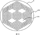
次に、図10を用いて本実施例に係る光学要素の第3の配列例を説明する。図10は、本実施例に係る光学部材2における光学要素の第3の配列例を示すものであって、光学部材2を光照射側から見た正面図を示している。   Next, a third arrangement example of optical elements according to the present embodiment will be described with reference to FIG. FIG. 10 shows a third arrangement example of the optical elements in the optical member 2 according to the present embodiment, and shows a front view of the optical member 2 viewed from the light irradiation side.

図10に示されるように、第3の配列例は、ある光源1に対応して光学要素251が配置された領域と、別の光源1に対応して光学要素が配置された領域とが、少なくともその一部において互いに交差或いは接触している。ここで、光学要素251は、図9に示した光学要素と同じ六角形状を為している。すなわち、本実施例では、ある光源1に対応して設けられた複数の光学要素251の一部と、別の光源1に対応して設けられた複数の光学要素251の一部とが、互いに交差或いは接触している。ここでは、照射面の外周付近において、ある光源1に対応して設けられた複数の光学要素251の一部と、別の光源1に対応して設けられた複数の光学要素251の一部とを互いに交差或いは接触させている。   As shown in FIG. 10, the third arrangement example includes an area where the optical element 251 is arranged corresponding to a certain light source 1 and an area where an optical element is arranged corresponding to another light source 1. At least some of them cross or touch each other. Here, the optical element 251 has the same hexagonal shape as the optical element shown in FIG. That is, in this embodiment, a part of a plurality of optical elements 251 provided corresponding to a certain light source 1 and a part of a plurality of optical elements 251 provided corresponding to another light source 1 are mutually connected. Crossing or touching. Here, in the vicinity of the outer periphery of the irradiation surface, a part of a plurality of optical elements 251 provided corresponding to a certain light source 1 and a part of a plurality of optical elements 251 provided corresponding to another light source 1 Are crossing or contacting each other.

本第3の配列例も第1または2の配列例のように、1つの光源1に対応して複数の光学要素251を配置する構成である。かかる構成では、複数の光源1が互いに隣接する領域において、ある光源1に対応する光学要素251に別の光源1から光束が入射した場合、その光束は当該ある光源1から入射した光束とは異なる特性で光学要素251から出射する。これは、セード3上で、光源1の境界部分における照度分布などの光学特性の不連続性の発生の原因となる。   As in the first or second arrangement example, the third arrangement example also has a configuration in which a plurality of optical elements 251 are arranged corresponding to one light source 1. In such a configuration, when a light beam from another light source 1 is incident on the optical element 251 corresponding to a certain light source 1 in a region where the plurality of light sources 1 are adjacent to each other, the light beam is different from the light beam incident from the certain light source 1. The light is emitted from the optical element 251 with characteristics. This causes a discontinuity of optical characteristics such as illuminance distribution at the boundary portion of the light source 1 on the shade 3.

これに対し第3の配列例の構成では、複数の光源1間の境界付近の、照射面の外周側には光学要素251を配置し、外周側以外(内側)の領域261には、光学要素251を設けず、これに代えて、例えば複数のプリズムまたはレンズを設けている。このプリズム、レンズに代えて、散乱特性を有する面設けてもよい。この構成によれば、光学部材2上の、複数の光源1間の境界付近の領域に、光学要素251の配置ピッチ相当で複数の特性が異なる光源を配置した状態を構成することができる。従って、この第3の配置例によれば、セード3を照明する際に、複数の光源1の境界付近でも極端な光学特性の変化を抑えた光学系を提供できる。上記複数のプリズムまたはレンズのそれぞれは、好ましくは光学要素251よりも小さいサイズを有している。しかしながら、光学要素251とほぼ同じ大きさとしてもよいし、若干大きなサイズとしてもよい。   On the other hand, in the configuration of the third arrangement example, the optical element 251 is arranged on the outer peripheral side of the irradiation surface near the boundary between the plurality of light sources 1, and the optical element is disposed in the region 261 other than the outer peripheral side (inner side). In place of this, for example, a plurality of prisms or lenses are provided. Instead of this prism and lens, a surface having scattering characteristics may be provided. According to this configuration, it is possible to configure a state in which a plurality of light sources having different characteristics corresponding to the arrangement pitch of the optical elements 251 are arranged in a region near the boundary between the plurality of light sources 1 on the optical member 2. Therefore, according to the third arrangement example, it is possible to provide an optical system that suppresses an extreme change in optical characteristics even near the boundaries of the plurality of light sources 1 when the shade 3 is illuminated. Each of the plurality of prisms or lenses preferably has a smaller size than the optical element 251. However, it may be approximately the same size as the optical element 251 or may be slightly larger.

なお、本発明は上記した実施例に限定されるものではなく、様々な変形例が含まれる。たとえば、上記した実施例は本発明を分かりやすく説明するために詳細に説明したものであり、必ずしも説明した全ての構成を備えるものに限定されるものではない。また、ある実施例の構成の一部を他の実施例の構成に置き換えることが可能であり、また、ある実施例の構成に他の実施例の構成を加えることも可能である。また、各実施例の構成の一部について、他の構成の追加・削除・置換をすることが可能である。   In addition, this invention is not limited to an above-described Example, Various modifications are included. For example, the above-described embodiments have been described in detail for easy understanding of the present invention, and are not necessarily limited to those having all the configurations described. Further, a part of the configuration of one embodiment can be replaced with the configuration of another embodiment, and the configuration of another embodiment can be added to the configuration of one embodiment. Further, it is possible to add, delete, and replace other configurations for a part of the configuration of each embodiment.

1…光源、2…光学部材、21、251…光学要素、211…入射面、212…出射面、3…セード、4…電源部、10…光源基板、213…入射側フレネルレンズ、214…出射側フレネルレンズ DESCRIPTION OF SYMBOLS 1 ... Light source, 2 ... Optical member, 21,251 ... Optical element, 211 ... Incident surface, 212 ... Outgoing surface, 3 ... Shade, 4 ... Power supply part, 10 ... Light source substrate, 213 ... Incident side Fresnel lens, 214 ... Outgoing Side Fresnel lens

Claims (16)

複数の光源と、透光性を有し該光源からの光を拡散して出射するための、外装ケースとしてのセードとを備えた照明装置において、
前記複数の光源と前記セードとの間に配置され、かつ前記光源からの光を屈折させるレンズ形状を有する複数の光学要素が二次元的に配列された光学部材を備え、
前記光学要素を介して前記光源からの出射光を前記セードに照射するように構成したことを特徴とする照明装置。
In an illuminating device comprising a plurality of light sources and a shade as an outer case for diffusing and emitting light from the light source,
An optical member that is arranged between the plurality of light sources and the shade and that has a plurality of optical elements having a lens shape that refracts light from the light source and is two-dimensionally arranged;
An illuminating device configured to irradiate the shade with light emitted from the light source through the optical element.
請求項1に記載の照明装置において、前記光源は、白色光を放出する白色LEDであることを特徴とする照明装置。   The lighting device according to claim 1, wherein the light source is a white LED that emits white light. 請求項1に記載の照明装置において、前記光学要素は、前記複数の光源のそれぞれに対応して複数設けられており、前記光学部材上の前記光学要素の数が前記光源の数よりも多いことを特徴とする照明装置。   2. The illumination device according to claim 1, wherein a plurality of the optical elements are provided corresponding to the plurality of light sources, and the number of the optical elements on the optical member is larger than the number of the light sources. A lighting device characterized by the above. 請求項3に記載の照明装置において、前記光学要素は、前記光源側に凸を向けた入射面と前記セード側に凸を向けた出射面とを含む両凸形状の正レンズであることを特徴とする照明装置。   4. The illumination device according to claim 3, wherein the optical element is a biconvex positive lens including an incident surface having a convex surface toward the light source and an exit surface having a convex surface toward the shade side. A lighting device. 請求項4に記載の照明装置において、前記入射面の焦点が前記出射面に位置していることを特徴とする照明装置。   5. The illuminating device according to claim 4, wherein a focal point of the incident surface is located on the exit surface. 請求項4に記載の照明装置において、前記出射面の焦点が前記入射面に位置していることを特徴とする照明装置。   5. The illuminating device according to claim 4, wherein a focal point of the emission surface is located on the incident surface. 請求項4に記載の照明装置において、前記入射面の中心と前記出射面の中心がほぼ一致していることを特徴とする照明装置。   5. The illuminating device according to claim 4, wherein the center of the incident surface and the center of the exit surface substantially coincide with each other. 請求項4に記載の照明装置において、前記複数の光学要素のうち前記1つの光源の光軸上に位置する光学要素の周囲に位置する光学要素の前記出射面の中心が、当該光学要素の前記入射面の中心よりも外側に位置していることを特徴とする照明装置。   5. The illumination device according to claim 4, wherein a center of the emission surface of an optical element positioned around an optical element positioned on an optical axis of the one light source among the plurality of optical elements is the optical element. An illumination device, wherein the illumination device is located outside the center of the incident surface. 請求項3に記載の照明装置において、前記光学要素は、前記複数の光源にそれぞれ対応して設けられた、前記光源側及び前記セード側に凸を向けたフレネルレンズであることを特徴とする照明装置。   4. The illumination device according to claim 3, wherein the optical element is a Fresnel lens provided corresponding to each of the plurality of light sources and having a convex surface directed toward the light source side and the shade side. apparatus. 請求項9に記載の照明装置において、前記フレネルレンズは、前記光学部材の前記光源側に設けられた入射側フレネルレンズと、前記光学部材の前記セード側に設けられた出射側フレネルレンズとを含み、前記入射側フレネルレンズの焦点が、当該入射側フレネルレンズに対応する前記光源の光放出面に位置することを特徴とする照明装置。   10. The illumination device according to claim 9, wherein the Fresnel lens includes an incident-side Fresnel lens provided on the light source side of the optical member and an emission-side Fresnel lens provided on the shade side of the optical member. The illumination apparatus is characterized in that a focal point of the incident-side Fresnel lens is located on a light emission surface of the light source corresponding to the incident-side Fresnel lens. 請求項4に記載の照明装置において、前記光学要素は、その光照射側から見た形状が円形を為すことを特徴とする照明装置。   5. The illumination device according to claim 4, wherein the optical element has a circular shape when viewed from the light irradiation side. 請求項4に記載の照明装置において、前記光学要素は、その光照射側から見た形状が多角形状を為すことを特徴とする照明装置。   5. The illumination device according to claim 4, wherein the optical element has a polygonal shape as viewed from the light irradiation side. 請求項4に記載の照明装置において、前記複数の光学要素は、前記光学部材において、前記1つの光源と対応する位置を基準に放射状に配列されていることを特徴とする照明装置。   5. The illumination device according to claim 4, wherein the plurality of optical elements are arranged radially on the optical member with reference to a position corresponding to the one light source. 請求項4に記載の照明装置において、各光源に対応して設けられた前記複数の光学要素は、互いに接触していることを特徴とする照明装置。   5. The illuminating device according to claim 4, wherein the plurality of optical elements provided corresponding to the respective light sources are in contact with each other. 請求項4に記載の照明装置において、各光源に対応して設けられた前記複数の光学要素は、前記光学部材において、前記1つの光源と対応する位置の光学要素の中心とそれに隣接する光学要素の中心を通る前記光学部材の面状の直線を基準に、対称に配列されていることを特徴とする照明装置。   5. The illumination device according to claim 4, wherein the plurality of optical elements provided corresponding to the respective light sources include, in the optical member, an optical element adjacent to the center of the optical element at a position corresponding to the one light source. The illumination device is arranged symmetrically with respect to a planar straight line of the optical member passing through the center of the optical member. 請求項4に記載の照明装置において、ある光源に対応して設けられた前記複数の光学要素の一部と、該ある光源とは異なる光源対応して設けられた前記複数の光学要素の一部とが互いに接触或いは交差していることを特徴とする照明装置。   5. The lighting device according to claim 4, wherein a part of the plurality of optical elements provided corresponding to a certain light source and a part of the plurality of optical elements provided corresponding to a light source different from the certain light source. Are in contact with or crossing each other.
JP2013077337A 2013-04-03 2013-04-03 Lighting device Pending JP2014203604A (en)

Priority Applications (1)

Application Number Priority Date Filing Date Title
JP2013077337A JP2014203604A (en) 2013-04-03 2013-04-03 Lighting device

Applications Claiming Priority (1)

Application Number Priority Date Filing Date Title
JP2013077337A JP2014203604A (en) 2013-04-03 2013-04-03 Lighting device

Publications (2)

Publication Number Publication Date
JP2014203604A true JP2014203604A (en) 2014-10-27
JP2014203604A5 JP2014203604A5 (en) 2015-11-12

Family

ID=52353891

Family Applications (1)

Application Number Title Priority Date Filing Date
JP2013077337A Pending JP2014203604A (en) 2013-04-03 2013-04-03 Lighting device

Country Status (1)

Country Link
JP (1) JP2014203604A (en)

Cited By (2)

* Cited by examiner, † Cited by third party
Publication number Priority date Publication date Assignee Title
CN106838722A (en) * 2017-01-19 2017-06-13 成都恒坤光电科技有限公司 A kind of colour temperature and adjustable-angle light fixture
US10312741B2 (en) 2013-04-08 2019-06-04 Sony Corporation Electronic unit and power feeding system

Citations (5)

* Cited by examiner, † Cited by third party
Publication number Priority date Publication date Assignee Title
JP2006302622A (en) * 2005-04-19 2006-11-02 Cheil Ind Co Ltd Surface light source device
JP2007134316A (en) * 2005-10-14 2007-05-31 Toshiba Corp Lighting apparatus
JP2007256933A (en) * 2007-02-19 2007-10-04 Rohm Co Ltd Lens array and method of manufacturing same
JP2009301753A (en) * 2008-06-10 2009-12-24 Sony Corp Light-emitting element module, planar light source, and liquid crystal display device
JP2012186022A (en) * 2011-03-04 2012-09-27 Mitsubishi Electric Corp Light source unit and lighting device

Patent Citations (5)

* Cited by examiner, † Cited by third party
Publication number Priority date Publication date Assignee Title
JP2006302622A (en) * 2005-04-19 2006-11-02 Cheil Ind Co Ltd Surface light source device
JP2007134316A (en) * 2005-10-14 2007-05-31 Toshiba Corp Lighting apparatus
JP2007256933A (en) * 2007-02-19 2007-10-04 Rohm Co Ltd Lens array and method of manufacturing same
JP2009301753A (en) * 2008-06-10 2009-12-24 Sony Corp Light-emitting element module, planar light source, and liquid crystal display device
JP2012186022A (en) * 2011-03-04 2012-09-27 Mitsubishi Electric Corp Light source unit and lighting device

Cited By (2)

* Cited by examiner, † Cited by third party
Publication number Priority date Publication date Assignee Title
US10312741B2 (en) 2013-04-08 2019-06-04 Sony Corporation Electronic unit and power feeding system
CN106838722A (en) * 2017-01-19 2017-06-13 成都恒坤光电科技有限公司 A kind of colour temperature and adjustable-angle light fixture

Similar Documents

Publication Publication Date Title
JP3931127B2 (en) LIGHTING DEVICE AND DISPLAY DEVICE USING THE SAME
JP5367850B2 (en) Lighting device
US8814410B2 (en) Lighting assembly with controlled configurable light redirection
JP2008515138A (en) Lighting system
US20100284201A1 (en) Illuminator using non-uniform light sources
US8956009B2 (en) Apparatus and methods for controlling a three-dimensional optical field
JP2015103323A (en) Luminaire
JP7123231B2 (en) Light source device
KR20120007015U (en) Polarizing beam splitter and projection apparatus
JP6446202B2 (en) Wide-angle diffusion optical system and illumination device using the same
JP5849192B2 (en) Surface light source and liquid crystal display device
JP6748424B2 (en) Light emitting device, surface light source device, and display device
WO2017002725A1 (en) Light-emitting device, surface light source device and display device
JP2014203604A (en) Lighting device
JP2018037257A (en) Surface light source device and liquid crystal display device
CN110360482B (en) Optical system and searchlight with diffuser and honeycomb concentrator
JP6298986B2 (en) Lighting device
JP6086766B2 (en) Planar light emitting device and liquid crystal display device
TW201506300A (en) Light source module
JP7300879B2 (en) Optical lens, light source device and illumination device
JP2018152177A (en) Light emitting diode lamp
JP7287668B2 (en) lighting equipment
US10677398B2 (en) Solid state light emitter lighting assembly and a luminaire
JP6639573B2 (en) Lighting lamp
JP6914091B2 (en) Light source device and lighting device

Legal Events

Date Code Title Description
A521 Written amendment

Free format text: JAPANESE INTERMEDIATE CODE: A523

Effective date: 20150824

A621 Written request for application examination

Free format text: JAPANESE INTERMEDIATE CODE: A621

Effective date: 20150824

A521 Written amendment

Free format text: JAPANESE INTERMEDIATE CODE: A523

Effective date: 20150824

A977 Report on retrieval

Free format text: JAPANESE INTERMEDIATE CODE: A971007

Effective date: 20160428

A131 Notification of reasons for refusal

Free format text: JAPANESE INTERMEDIATE CODE: A131

Effective date: 20160510

A02 Decision of refusal

Free format text: JAPANESE INTERMEDIATE CODE: A02

Effective date: 20161108