JP2014201122A - Retractor for seat belt - Google Patents
Retractor for seat belt Download PDFInfo
- Publication number
- JP2014201122A JP2014201122A JP2013077073A JP2013077073A JP2014201122A JP 2014201122 A JP2014201122 A JP 2014201122A JP 2013077073 A JP2013077073 A JP 2013077073A JP 2013077073 A JP2013077073 A JP 2013077073A JP 2014201122 A JP2014201122 A JP 2014201122A
- Authority
- JP
- Japan
- Prior art keywords
- winding drum
- rotation
- webbing
- retractor
- relay
- Prior art date
- Legal status (The legal status is an assumption and is not a legal conclusion. Google has not performed a legal analysis and makes no representation as to the accuracy of the status listed.)
- Granted
Links
- 230000007246 mechanism Effects 0.000 claims abstract description 178
- 238000004804 winding Methods 0.000 claims description 216
- 230000033001 locomotion Effects 0.000 claims description 48
- 230000000452 restraining effect Effects 0.000 claims description 42
- 230000001105 regulatory effect Effects 0.000 claims description 15
- 230000008844 regulatory mechanism Effects 0.000 abstract 1
- 230000002093 peripheral effect Effects 0.000 description 60
- 238000000605 extraction Methods 0.000 description 26
- 230000004048 modification Effects 0.000 description 23
- 238000012986 modification Methods 0.000 description 23
- 230000005540 biological transmission Effects 0.000 description 18
- 230000001133 acceleration Effects 0.000 description 14
- 230000003111 delayed effect Effects 0.000 description 11
- 239000000463 material Substances 0.000 description 9
- 229910000831 Steel Inorganic materials 0.000 description 7
- 230000035939 shock Effects 0.000 description 7
- 239000010959 steel Substances 0.000 description 7
- 238000000034 method Methods 0.000 description 6
- 238000010521 absorption reaction Methods 0.000 description 5
- 239000011347 resin Substances 0.000 description 5
- 229920005989 resin Polymers 0.000 description 5
- 238000004519 manufacturing process Methods 0.000 description 4
- 239000003795 chemical substances by application Substances 0.000 description 3
- 238000003780 insertion Methods 0.000 description 3
- 230000037431 insertion Effects 0.000 description 3
- 102000007315 Telomeric Repeat Binding Protein 1 Human genes 0.000 description 2
- 108010033711 Telomeric Repeat Binding Protein 1 Proteins 0.000 description 2
- 230000008859 change Effects 0.000 description 2
- 229920001971 elastomer Polymers 0.000 description 2
- 229910052751 metal Inorganic materials 0.000 description 2
- 239000002184 metal Substances 0.000 description 2
- 239000007779 soft material Substances 0.000 description 2
- 102000005591 NIMA-Interacting Peptidylprolyl Isomerase Human genes 0.000 description 1
- 108010059419 NIMA-Interacting Peptidylprolyl Isomerase Proteins 0.000 description 1
- 230000004308 accommodation Effects 0.000 description 1
- 229910052782 aluminium Inorganic materials 0.000 description 1
- XAGFODPZIPBFFR-UHFFFAOYSA-N aluminium Chemical compound [Al] XAGFODPZIPBFFR-UHFFFAOYSA-N 0.000 description 1
- 230000008878 coupling Effects 0.000 description 1
- 238000010168 coupling process Methods 0.000 description 1
- 238000005859 coupling reaction Methods 0.000 description 1
- 230000001934 delay Effects 0.000 description 1
- 238000001514 detection method Methods 0.000 description 1
- 238000010586 diagram Methods 0.000 description 1
- 239000000806 elastomer Substances 0.000 description 1
- 238000005516 engineering process Methods 0.000 description 1
- 239000002360 explosive Substances 0.000 description 1
- 239000007769 metal material Substances 0.000 description 1
- 230000000149 penetrating effect Effects 0.000 description 1
- 230000003014 reinforcing effect Effects 0.000 description 1
- 239000011435 rock Substances 0.000 description 1
- 238000010079 rubber tapping Methods 0.000 description 1
Images


Classifications
-
- B—PERFORMING OPERATIONS; TRANSPORTING
- B60—VEHICLES IN GENERAL
- B60R—VEHICLES, VEHICLE FITTINGS, OR VEHICLE PARTS, NOT OTHERWISE PROVIDED FOR
- B60R22/00—Safety belts or body harnesses in vehicles
- B60R22/34—Belt retractors, e.g. reels
- B60R22/341—Belt retractors, e.g. reels comprising energy-absorbing means
- B60R22/3413—Belt retractors, e.g. reels comprising energy-absorbing means operating between belt reel and retractor frame
-
- B—PERFORMING OPERATIONS; TRANSPORTING
- B60—VEHICLES IN GENERAL
- B60R—VEHICLES, VEHICLE FITTINGS, OR VEHICLE PARTS, NOT OTHERWISE PROVIDED FOR
- B60R22/00—Safety belts or body harnesses in vehicles
- B60R22/34—Belt retractors, e.g. reels
- B60R22/46—Reels with means to tension the belt in an emergency by forced winding up
- B60R22/4628—Reels with means to tension the belt in an emergency by forced winding up characterised by fluid actuators, e.g. pyrotechnic gas generators
- B60R22/4633—Linear actuators, e.g. comprising a piston moving along reel axis and rotating along its own axis
-
- B—PERFORMING OPERATIONS; TRANSPORTING
- B60—VEHICLES IN GENERAL
- B60R—VEHICLES, VEHICLE FITTINGS, OR VEHICLE PARTS, NOT OTHERWISE PROVIDED FOR
- B60R22/00—Safety belts or body harnesses in vehicles
- B60R22/28—Safety belts or body harnesses in vehicles incorporating energy-absorbing devices
- B60R2022/286—Safety belts or body harnesses in vehicles incorporating energy-absorbing devices using deformation of material
- B60R2022/287—Safety belts or body harnesses in vehicles incorporating energy-absorbing devices using deformation of material of torsion rods or tubes
-
- B—PERFORMING OPERATIONS; TRANSPORTING
- B60—VEHICLES IN GENERAL
- B60R—VEHICLES, VEHICLE FITTINGS, OR VEHICLE PARTS, NOT OTHERWISE PROVIDED FOR
- B60R22/00—Safety belts or body harnesses in vehicles
- B60R22/34—Belt retractors, e.g. reels
- B60R22/46—Reels with means to tension the belt in an emergency by forced winding up
- B60R2022/468—Reels with means to tension the belt in an emergency by forced winding up characterised by clutching means between actuator and belt reel
Landscapes
- Engineering & Computer Science (AREA)
- Mechanical Engineering (AREA)
- Automotive Seat Belt Assembly (AREA)
Abstract
Description
この発明は、車両緊急時にウエビングにより乗員を拘束するシートベルト用リトラクタに関し、特に、ウエビングによる乗員への衝撃エネルギーを吸収するためのウエビング引出荷重の発生開始タイミングを調整するための技術に関する。 The present invention relates to a seatbelt retractor that restrains an occupant by webbing in the event of a vehicle emergency, and more particularly to a technique for adjusting the generation start timing of a webbing extraction load for absorbing impact energy to the occupant by webbing.
従来、この種のシートベルト用リトラクタとして、特許文献1〜3に開示のものがある。 Conventionally, as this type of seat belt retractor, there are those disclosed in Patent Documents 1 to 3.
特許文献1は、ウエビングが巻装されるボビンと、車両緊急時に回転阻止されるロッキングデバイスと、ロッキングデバイスとボビンとの双方に係合する抵抗部材を有しロッキングデバイスとボビンとの相対回転の際に衝撃エネルギーの吸収を行う第2のエネルギー吸収機構とを備えたシートベルト装置を開示している。このシートベルト装置では、ボビンが所定量回転した後に、第2のエネルギー吸収機構によるエネルギー吸収が行われるように、抵抗部材とロッキングデバイス及びボビンの少なくとも一方の係合状態に、待機状態においてあそびが設けられている。 Patent Document 1 discloses a bobbin around which a webbing is wound, a locking device that is prevented from rotating in an emergency of a vehicle, a resistance member that engages both the locking device and the bobbin, and a relative rotation between the locking device and the bobbin. A seat belt device including a second energy absorbing mechanism that absorbs impact energy is disclosed. In this seat belt device, in a standby state, play is performed in the engagement state of at least one of the resistance member, the locking device, and the bobbin so that energy absorption by the second energy absorption mechanism is performed after the bobbin rotates by a predetermined amount. Is provided.
特許文献2は、トーションバーのねじれ変形による塑性変形が開始されるまで、ロッキングベースに対して巻取ドラムが相対回転可能な空走領域が、巻取ドラムとロッキングベース又は第2のエネルギー吸収部材との相互間に設けられた技術が開示されている。空走期間は、例えば、ロッキングベースに設けられたスプライン部がプレート体に設けられたスプライン溝部に挿入され、これらスプライン部とスプライン溝部との相互間に、空走回転領域を設けることにより実現されている。 Patent Document 2 discloses that the idle running region in which the winding drum can rotate relative to the locking base until the plastic deformation due to the torsional deformation of the torsion bar is started is the winding drum and the locking base or the second energy absorbing member. And a technology provided between them. The idling period is realized, for example, by inserting a spline portion provided on the locking base into a spline groove portion provided on the plate body and providing an idling rotation region between the spline portion and the spline groove portion. ing.
特許文献3は、巻取ドラムと回転規制部材との間に設けられた中間回転部材と、一端部が中間回転部材に取付けられると共に他端部が巻取ドラムと回転規制部材の一方に取付けられた第2衝撃吸収部材と、巻取ドラムと回転規制部材の他方に設けられ、巻取ドラムと回転規制部材の他方に対して中間回転部材が所定量回転すると、巻取ドラムと回転規制部材の他方に対する中間回転部材の回転を規制するストッパ部とを備えた構成が開示されている。 In Patent Document 3, an intermediate rotating member provided between the winding drum and the rotation restricting member, one end portion is attached to the intermediate rotating member, and the other end portion is attached to one of the winding drum and the rotation restricting member. Provided on the other of the second shock absorbing member, the winding drum and the rotation restricting member, and when the intermediate rotating member rotates a predetermined amount relative to the other of the winding drum and the rotation restricting member, the winding drum and the rotation restricting member The structure provided with the stopper part which controls rotation of the intermediate | middle rotating member with respect to the other is disclosed.
しかしながら、特許文献1〜特許文献3に開示の技術では、ウエビング引出荷重の発生開始タイミングの自由度が低いという問題がある。 However, the techniques disclosed in Patent Documents 1 to 3 have a problem that the degree of freedom of the start timing of occurrence of the webbing pull-out load is low.
そこで、本発明は、ウエビング引出荷重の発生開始タイミングの自由度を向上させることを目的とする。 Accordingly, an object of the present invention is to improve the degree of freedom of the timing for starting the generation of the webbing withdrawal load.
上記課題を解決するため、第1の態様に係るシートベルト用リトラクタは、ウエビングが巻回された巻取ドラムと、前記巻取ドラムの回転軸と同軸上で回転可能な状態と、前記ウエビングへの引出方向への回転を規制された状態とで切替えられる回転規制部材と、一端側が前記巻取ドラム及び前記回転規制部材の一方に相対回転不能に取付けられ、ねじれ変形によりウエビング引出荷重を発生させるトーションバーとして用いられる中継部材と、前記巻取ドラム及び前記回転規制部材の他方と前記中継部材の他端側との間に設けられ、前記巻取ドラム及び前記回転規制部材の他方と前記中継部材とが所定量相対回転する前の状態では前記巻取ドラム及び前記回転規制部材の他方と前記中継部材との相対回転を許容すると共に、前記巻取ドラム及び前記回転規制部材の他方と前記中継部材とが所定量相対回転した後に前記巻取ドラム及び前記回転規制部材の他方と前記中継部材とを相対回転不能に拘束する拘束機構と、を備える。 In order to solve the above-described problem, a retractor for a seat belt according to a first aspect includes a winding drum on which a webbing is wound, a state in which the webbing can be rotated coaxially with a rotation shaft of the winding drum, and the webbing. A rotation restricting member that can be switched in a state in which rotation in the pull-out direction is restricted, and one end side is attached to one of the winding drum and the rotation restricting member so as not to be relatively rotatable, and generates a webbing pull-out load by torsional deformation. A relay member used as a torsion bar; provided between the other of the winding drum and the rotation restricting member and the other end of the relay member; and the other of the winding drum and the rotation restricting member and the relay member Is allowed to rotate relative to the relay member and the other of the winding drum and the rotation restricting member in a state before the relative rotation of the winding drum, and the winding drum. The other and the relay member of finely the rotation restricting member and a restraining mechanism for non-rotatably restrained and the other with the relay member of the winding drum and the rotation restricting member after rotated by a predetermined amount relative.
第2の態様は、第1の態様に係るシートベルト用リトラクタであって、前記拘束機構は、前記巻取ドラム及び前記回転規制部材の他方と前記中継部材との相対回転に応じて前記巻取ドラムの回転軸方向に沿って移動可能な可動部と、前記可動部の所定量以上の移動を規制する規制部とを含み、前記規制部が前記可動部の移動を規制することで、前記巻取ドラム及び前記回転規制部材の他方と前記中継部材との所定量を超える相対回転を規制する。 A second aspect is a seatbelt retractor according to the first aspect, wherein the restraining mechanism is configured to take up the winding drum according to relative rotation between the winding drum and the other of the rotation regulating member and the relay member. A movable part movable along the rotation axis direction of the drum, and a restriction part for restricting movement of the movable part by a predetermined amount or more, and the restriction part restricts movement of the movable part, A relative rotation exceeding a predetermined amount between the take-up drum and the other of the rotation regulating member and the relay member is regulated.
第3の態様に係るシートベルト用リトラクタは、ウエビングが巻回された巻取ドラムと、前記巻取ドラムの回転軸と同軸上で回転可能な状態と、前記ウエビングへの引出方向への回転を規制された状態とで切替えられる回転規制部材と、一端側が前記巻取ドラム及び前記回転規制部材の一方に相対回転不能に取付けられた、衝撃吸収部材としての中継部材と、前記巻取ドラム及び前記回転規制部材の他方と前記中継部材の他端側との間に設けられ、前記巻取ドラム及び前記回転規制部材の他方と前記中継部材との相対回転に応じて前記巻取ドラムの回転軸方向に沿って移動可能な可動部と、前記可動部の所定量以上の移動を規制する規制部とを含み、前記規制部が前記可動部の移動を規制することで、前記巻取ドラム及び前記回転規制部材の他方と前記中継部材との所定量を超える相対回転を規制する拘束機構と、を備え、前記巻取ドラムから前記中継部材を経由して前記回転規制部材に至る部分のいずれかの部分に、前記拘束機構により前記巻取ドラム及び前記回転規制部材の他方と前記中継部材との相対回転が規制されると、前記中継部材によってウエビング引出荷重を発生させる衝撃吸収機構が組込まれている。 The seatbelt retractor according to the third aspect includes a winding drum around which the webbing is wound, a state in which the webbing can be rotated coaxially with a rotation shaft of the winding drum, and rotation in the pull-out direction to the webbing. A rotation restricting member that is switched between a restricted state, a relay member serving as an impact absorbing member, one end of which is attached to one of the take-up drum and the rotation restricting member so as not to be relatively rotatable, the take-up drum, and the A rotation axis direction of the take-up drum is provided between the other of the rotation restricting member and the other end of the relay member, and according to relative rotation between the take-up drum and the other of the rotation restricting member and the relay member. And a restricting part that restricts movement of the movable part by a predetermined amount or more, and the restricting part restricts movement of the movable part, whereby the winding drum and the rotation Regulatory member And a restraining mechanism for restricting relative rotation exceeding a predetermined amount between the winding member and the relay member, and in any part of the portion from the winding drum to the rotation restricting member via the relay member, When the relative rotation of the relay member with the other of the winding drum and the rotation restricting member is restricted by the restraining mechanism, an impact absorbing mechanism for generating a webbing pull-out load by the relay member is incorporated.
第4の態様は、第2又は第3の態様に係るシートベルト用リトラクタであって、前記拘束機構は、軸部材と、前記軸部材に外嵌め可能に構成されたリング部材とを含み、前記軸部材及び前記リング部材のいずれか一方が前記中継部材に相対回転不能に設けられると共に、前記軸部材及び前記リング部材のいずれか他方が前記巻取ドラム及び前記回転規制部材のいずれか一方に相対回転不能に設けられ、前記軸部材及び前記リング部材の少なくとも一方が、前記可動部として、前記巻取ドラムの回転軸方向に沿って移動可能とされており、前記軸部材と前記リング部材とが相対回転することで、前記軸部材と前記リング部材とが前記巻取ドラムの回転軸方向に沿って相対移動可能に構成され、前記規制部が、前記軸部材と前記リング部材との相対回転が所定量を超えると、前記軸部材と前記リング部材との前記巻取ドラムの回転軸方向に沿った相対移動を規制するように設けられている。 A fourth aspect is a seat belt retractor according to the second or third aspect, wherein the restraining mechanism includes a shaft member and a ring member configured to be externally fitted to the shaft member, Either the shaft member or the ring member is provided on the relay member so as not to rotate relative to the relay member, and the other of the shaft member and the ring member is relative to either the winding drum or the rotation restricting member. The shaft member and the ring member are non-rotatable, and at least one of the shaft member and the ring member is movable as the movable portion along a rotation axis direction of the winding drum, and the shaft member and the ring member are By the relative rotation, the shaft member and the ring member are configured to be relatively movable along the direction of the rotation axis of the winding drum, and the restricting portion is a phase between the shaft member and the ring member. Rotation is provided so as exceeds a predetermined amount, to restrict the relative movement along the rotation axis direction of the winding drum and said ring member and said shaft member.
第5の態様は、第4の態様に係るシートベルト用リトラクタであって、前記軸部材は、雄ねじ部分を含み、前記リング部材が、前記雄ねじ部分を螺合可能な雌ねじ部分を含む。 A fifth aspect is a seat belt retractor according to the fourth aspect, wherein the shaft member includes a male screw part, and the ring member includes a female screw part capable of screwing the male screw part.
第6の態様は、第4又は第5の態様に係るシートベルト用リトラクタであって、前記軸部材及び前記リング部材のいずれか一方が前記中継部材に一体形成されているものである。 A sixth aspect is a seat belt retractor according to the fourth or fifth aspect, wherein either one of the shaft member and the ring member is integrally formed with the relay member.
第7の態様は、第4〜第6のいずれか1つの態様に係るシートベルト用リトラクタであって、前記軸部材及び前記リング部材のいずれか一方が、前記中継部材とは別体に形成されて、前記中継部材に取付けられているものである。 A seventh aspect is a seatbelt retractor according to any one of the fourth to sixth aspects, wherein either the shaft member or the ring member is formed separately from the relay member. And attached to the relay member.
第8の態様は、第4〜第7のいずれか1つの態様に係るシートベルト用リトラクタであって、前記軸部材と前記リング部材とが相対回転することで、前記軸部材と前記リング部材との少なくとも一方が塑性変形しつつ、前記軸部材と前記リング部材とが前記巻取ドラムの回転軸方向に沿って相対移動するものである。 An eighth aspect is a seatbelt retractor according to any one of the fourth to seventh aspects, wherein the shaft member and the ring member are rotated by relative rotation of the shaft member and the ring member. The shaft member and the ring member relatively move along the direction of the rotation axis of the winding drum while at least one of the members is plastically deformed.
第9の態様は、第1〜第8のいずれか1つの態様に係るシートベルト用リトラクタであって、待機状態では前記巻取ドラムと前記回転規制部材とを相対回転不能に連結しており、前記巻取ドラムに、衝撃による前記ウエビングの引出方向への力が加わると、ウエビング引出荷重を発生させつつ、前記巻取ドラムと前記回転規制部材との相対回転を許容する、衝撃吸収部材をさらに備える。 A ninth aspect is a seatbelt retractor according to any one of the first to eighth aspects, wherein the winding drum and the rotation regulating member are connected in a non-rotatable state in a standby state, An impact absorbing member that allows relative rotation between the take-up drum and the rotation restricting member while generating a webbing pull-out load when a force in the pull-out direction of the webbing is applied to the take-up drum; Prepare.
第10の態様は、第9の態様に係るシートベルト用リトラクタであって、前記衝撃吸収部材によるウエビング引出荷重発生中に、前記中継部材によるウエビング引出荷重の発生が開始するように設定されているものである。 A tenth aspect is a seatbelt retractor according to the ninth aspect, and is set so that the generation of the webbing pull-out load by the relay member starts during the generation of the webbing pull-out load by the shock absorbing member. Is.
第11の態様は、第9又は第10の態様に係るシートベルト用リトラクタであって、前記衝撃吸収部材は、前記巻取ドラムと前記回転規制部材との相対回転によって、変形しつつ引出されるワイヤーを含む。 An eleventh aspect is a seatbelt retractor according to the ninth or tenth aspect, wherein the impact absorbing member is pulled out while being deformed by relative rotation between the winding drum and the rotation restricting member. Includes wire.
第1の態様によると、前記巻取ドラム及び前記回転規制部材の他方と前記中継部材とが所定量相対回転した後に、前記巻取ドラム及び前記回転規制部材の他方と前記中継部材とが相対回転不能に拘束され、トーションバーとしての中継部材が捩れ変形する。このため、トーションバーとしての中継部材による、ウエビング引出荷重発生動作の開始タイミングを遅らせて、ウエビング引出荷重発生動作のタイミングの自由度を向上させることができる。 According to the first aspect, after the other of the winding drum and the rotation restricting member and the relay member are relatively rotated by a predetermined amount, the other of the winding drum and the rotation restricting member and the relay member are relatively rotated. The relay member serving as a torsion bar is twisted and deformed by being disabled. For this reason, the start timing of the webbing pull-out load generation operation by the relay member as a torsion bar can be delayed, and the degree of freedom of the timing of the webbing pull-out load generation operation can be improved.
第2の態様によると、前記規制部が前記可動部の移動を規制することで、前記巻取ドラム及び前記回転規制部材の他方と前記中継部材との所定量を超える相対回転が規制されると、衝撃吸収機構によってウエビング引出荷重が発生する。ここで、拘束機構は、前記巻取ドラム及び前記回転規制部材の他方と前記中継部材との相対回転に応じて前記巻取ドラムの回転軸方向に沿って移動可能な可動部と、前記可動部の所定量以上の移動を規制する規制部とを含み、前記規制部が前記可動部の移動を規制することで、前記巻取ドラム及び前記回転規制部材の他方と前記中継部材との所定量を超える相対回転を規制する構成とされている。このため、前記巻取ドラム及び前記回転規制部材の他方と前記中継部材とが1回以上相対回転した後に、ウエビング引出荷重を発生させることができ、ウエビング引出荷重発生動作のタイミングの自由度を向上させることができる。 According to the second aspect, when the restriction portion restricts the movement of the movable portion, relative rotation exceeding a predetermined amount between the other of the winding drum and the rotation restriction member and the relay member is restricted. The webbing pull-out load is generated by the shock absorbing mechanism. Here, the restraining mechanism includes a movable part movable along the rotation axis direction of the take-up drum according to relative rotation between the other of the take-up drum and the rotation regulating member and the relay member, and the movable part A restriction portion that restricts movement of a predetermined amount or more, and the restriction portion restricts movement of the movable portion, whereby a predetermined amount of the other of the winding drum and the rotation restriction member and the relay member is set. It is set as the structure which controls the relative rotation which exceeds. For this reason, the webbing pull-out load can be generated after the other of the winding drum and the rotation restricting member and the relay member are relatively rotated one or more times, and the degree of freedom in the timing of the webbing pull-out load generating operation is improved. Can be made.
第3の態様によると、前記規制部が前記可動部の移動を規制することで、前記巻取ドラム及び前記回転規制部材の他方と前記中継部材との所定量を超える相対回転が規制されると、衝撃吸収機構によってウエビング引出荷重が発生する。ここで、拘束機構は、前記巻取ドラム及び前記回転規制部材の他方と前記中継部材との相対回転に応じて前記巻取ドラムの回転軸方向に沿って移動可能な可動部と、前記可動部の所定量以上の移動を規制する規制部とを含み、前記規制部が前記可動部の移動を規制することで、前記巻取ドラム及び前記回転規制部材の他方と前記中継部材との所定量を超える相対回転を規制する構成とされている。このため、前記巻取ドラム及び前記回転規制部材の他方と前記中継部材とが1回以上相対回転した後に、ウエビング引出荷重を発生させることができ、ウエビング引出荷重発生動作のタイミングの自由度を向上させることができる。 According to the third aspect, when the restricting portion restricts movement of the movable portion, relative rotation exceeding a predetermined amount between the other of the winding drum and the rotation restricting member and the relay member is restricted. The webbing pull-out load is generated by the shock absorbing mechanism. Here, the restraining mechanism includes a movable part movable along the rotation axis direction of the take-up drum according to relative rotation between the other of the take-up drum and the rotation regulating member and the relay member, and the movable part A restriction portion that restricts movement of a predetermined amount or more, and the restriction portion restricts movement of the movable portion, whereby a predetermined amount of the other of the winding drum and the rotation restriction member and the relay member is set. It is set as the structure which controls the relative rotation which exceeds. For this reason, the webbing pull-out load can be generated after the other of the winding drum and the rotation restricting member and the relay member are relatively rotated one or more times, and the degree of freedom in the timing of the webbing pull-out load generating operation is improved. Can be made.
第4の態様によると、前記軸部材と前記リング部材との相対回転が所定量を超えると、規制部が軸部材及びリング部材の少なくとも一方の相対移動を規制することで、それらの相対回転を規制し、もって、ウエビング引出荷重を発生させることができる。 According to the fourth aspect, when the relative rotation between the shaft member and the ring member exceeds a predetermined amount, the restricting portion restricts the relative movement of at least one of the shaft member and the ring member, so that the relative rotation is prevented. The webbing pull-out load can be generated by regulating.
第5の態様によると、雄ねじ部分と雌ねじ部分との螺合によって、軸部材とリング部材との相対回転によってそれらをより確実に回転軸方向に相対移動させることができる。 According to the fifth aspect, by screwing the male screw portion and the female screw portion, the shaft member and the ring member can be relatively moved relative to each other in the rotational axis direction by the relative rotation of the shaft member and the ring member.
第6の態様によると、前記軸部材及び前記リング部材のいずれか一方と前記中継部材とを容易に製作できる。 According to the sixth aspect, any one of the shaft member and the ring member and the relay member can be easily manufactured.
第7の態様によると、中継部材と、前記軸部材及び前記リング部材のいずれか一方とを、それぞれの目的に適した材料で形成できる。例えば、前記軸部材及び前記リング部材のいずれか一方については、上記拘束機構としての機能に適するように比較的硬い材料で形成し、中継部材については、トーションバーとしての機能に適するように比較的柔らかい材料で形成することができる。 According to the 7th aspect, a relay member and any one of the said shaft member and the said ring member can be formed with the material suitable for each objective. For example, one of the shaft member and the ring member is formed of a relatively hard material so as to be suitable for the function as the restraining mechanism, and the relay member is comparatively suitable for the function as a torsion bar. It can be made of a soft material.
第8の態様によると、前記軸部材と前記リング部材とが相対回転する際、前記軸部材と前記リング部材との少なくとも一方が塑性変形することにより、ウエビング引出荷重を発生させることができる。 According to the eighth aspect, when the shaft member and the ring member rotate relative to each other, at least one of the shaft member and the ring member is plastically deformed, so that a webbing extraction load can be generated.
第9の態様によると、衝撃吸収部材によって、多様なウエビング引出荷重を発生させることができる。 According to the ninth aspect, various webbing pull-out loads can be generated by the impact absorbing member.
第10の態様によると、衝撃吸収部材によるウエビング引出荷重に、中継部材によるウエビング引出荷重を加重して、段階的にウエビング引出荷重を大きくすることができる。 According to the tenth aspect, it is possible to increase the webbing withdrawal load stepwise by applying the webbing withdrawal load by the relay member to the webbing withdrawal load by the impact absorbing member.
第11の態様によると、ワイヤーの変形によって、ウエビング引出荷重を発生させることができる。 According to the eleventh aspect, the webbing pull-out load can be generated by the deformation of the wire.
<全体構成>
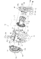
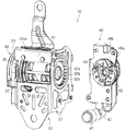
以下、実施形態に係るシートベルト用リトラクタ10について説明する。図1はシートベルト用リトラクタ10の全体構成を示す斜視図であり、図2はシートベルト用リトラクタ10を機能単位で分解した斜視図であり、図3及び図4はシートベルト用リトラクタ10をさらに細かく分解した斜視図である。図3は主として巻取ドラム30及びその一端側に組付けられる部品を示しており、図4は主として巻取ドラム30の他端側に組付けられる部品を示している。
<Overall configuration>
Hereinafter, the
このシートベルト用リトラクタ10は、車両等の座席に備えられるシートベルト装置に適用されるものである。このシートベルト用リトラクタ10は、車両のセンターピラー下部等に組込まれており、通常状態では、シートベルトとしてのウエビング12を引出及び巻取可能に収容している。このシートベルト用リトラクタ10は、車両の加速時(減速時等を含む)の非通常状態時には、乗員を効果的に拘束するため、ウエビング12の引出を規制する。特に、車両の衝突時或は急激な減速時等の緊急時には、シートベルト用リトラクタ10は、弛みを除去するようにウエビング12を巻取り、その後、乗員に加わる衝撃を緩和するようにウエビング12を徐々に繰出すように構成されている。
The
すなわち、シートベルト用リトラクタ10は、ハウジング20と、巻取ドラム30と、プリテンショナー機構40と、巻取機構100と、ロック機構60とを備えている。巻取ドラム30とロック機構60との間に引出荷重発生機構が設けられている。ここでは、引出荷重発生機構は、ワイヤー式引出荷重発生機構80とトーションバー式引出荷重発生機構90とを備える。巻取ドラム30は、ハウジング20内に収容されており、巻取ドラム30の一端側(図1の右側)にプリテンショナー機構40が組込まれ、巻取ドラム30の他端側(図1の左側)に巻取機構100及びロック機構60が組込まれている。そして、巻取機構100が巻取ドラム30をウエビング12の巻取方向に付勢するように構成されている。そして、通常状態においては、巻取機構100の付勢力によって巻取ドラム30がウエビング12の巻取方向に付勢されており、前記巻取機構100の付勢力に抗してウエビング12を引出すことができ、また、ウエビング12の引出力を解除すると、巻取機構100の付勢力によってウエビング12が巻取ドラム30に巻取られる。また、ロック機構60が車両の減速時等の非通常状態時(車両の衝突時或は急激な減速時等の緊急時を含む)に、ウエビング12の引出方向への巻取ドラム30の回転を規制するように構成される。さらに、プリテンショナー機構40は、車両緊急時等に、ウエビング12の巻取方向に巻取ドラム30を回転させるように構成されている。ロック機構60の作動後、かつ、プリテンショナー機構40が車両緊急時等にウエビング12の巻取方向に巻取ドラム30を回転させた後、上記引出荷重発生機構は、ウエビング12を繰出すように巻取ドラム30の回転を許容すると共に、ウエビング12の引出す際に抵抗となる引出荷重を発生させ、もって、急な減速によって車両前方に移動しようとする乗員の衝撃を緩和しつつ受止める役割を果す。
That is, the
<ハウジング及び巻取ドラム>
ハウジング20は、金属板等によって形成された部材であり、相対向して設けられた一対の側板部21、22と、当該側板部21、22の縁部同士を連結する複数の連結板部23、24とを備えている。側板部21、22には、巻取ドラム30の端部を外部に臨ませる開口21h、22hが形成されている。また、連結板部23は、側板部21、22の他の縁部(図1では上側の縁部)間の位置に延出する部分23aを有しており、この部分23aにウエビング12を外部に引出すための開口23ahが形成されている。ここでは、開口23ahには、ウエビング12を挿通可能なスリット状の開口が形成された樹脂製のガイド部材23bが装着されている。また、連結板部23の前記部分23aには、本シートベルト用リトラクタ10を車体等に取付けるためのねじ穴が形成されたねじ固定片23cが形成されている。
<Housing and winding drum>
The
そして、一対の側板部21、22間に巻取ドラム30を配設した状態で、一方の側板部21の外面にプリテンショナー機構40が取付けられると共に、他方の側板部22の外面にロック機構60が取付けられる。
The
巻取ドラム30は、ウエビング12が巻回された状態でハウジング20内に回転可能に配設される部材である。具体的には、巻取ドラム30は、アルミニウム等により形成されており、円柱状の巻取ドラム本体部31と、その巻取ドラム本体部31の軸芯方向両端部に径方向に張出すように形成されたフランジ部32、34を有している。ウエビング12は、両フランジ部32、34間で巻取ドラム本体部31に巻取られる。
The winding
また、巻取ドラム30には、その中心軸に沿って軸孔部36が形成されている。軸孔部36は、巻取ドラム30の一端部側では非貫通であり、巻取ドラム30の他端部側では開口している。この軸孔部36には、トーションバー38が挿入されている。トーションバー38の一端部38aは、巻取ドラム30の他端側におけるフランジ部34から外部に突出しており、ロック機構60のラチェットギヤ61(後述する)と相対回転不能に結合される。また、トーションバー38の他端部38bは、軸孔部36内部において、後に詳述する拘束機構92を介して巻取ドラム30に連結されている。
Further, the winding
<プリテンショナー機構>
図5はシートベルト用リトラクタ10からプリテンショナー機構40を分解した状態を示す斜視図であり、図6はプリテンショナー機構40の内部構造を示す説明図である。図1〜図3、図5及び図6に示すように、プリテンショナー機構40は、車両の衝突時等の緊急時に、ウエビング12の巻取方向に巻取ドラム30を回転させることによって、ウエビング12の弛みを除去するための機構である。このように車両の衝突時等の緊急時において、ウエビング12の弛みを除去することによって、乗員をしっかりと座席に拘束することができる。
<Pretensioner mechanism>
FIG. 5 is a perspective view showing a state in which the
より具体的には、プリテンショナー機構40は、ガス発生部材41と、パイプシリンダ42と、ピストン43と、ピニオンギヤ45と、クラッチ機構50とを備えている。
More specifically, the
ガス発生部材41は、火薬等のガス発生剤を有しており、衝撃検知センサ等の出力に応じて前記ガス発生剤を着火させてガスを発生させる構成とされている。
The
パイプシリンダ42は、直線状のピストン案内筒部42aの一端部にガス導入部42bが連設されたL字状の筒部材に形成されている。このガス導入部42bに上記ガス発生部材41が装着されている。従って、ガス発生部材41により発生されたガスは、パイプシリンダ42のガス導入部42b側(図6等で下側)からピストン案内筒部42a内にガスが導入される。また、ピストン案内筒部42aの一側部における長手方向中間部には、開口部42ahが形成されている。この開口部42ahに、後述するピニオンギヤ45のピニオンギヤ歯45aの一部分が配設される。
The
このパイプシリンダ42は、側板部21側のベースプレート48aと外側のカバープレート48bとによって挟持されると共に、これらの間でベースブロック49とカバープレート48bとによって挟持された状態で、タッピングネジPIN1等を用いて側板部21の外面に取付固定される。
The
なお、ピストン案内筒部42aの上端部には、プリテンショナー機構40をハウジング20に取付けるとともに、ピストン43の抜止及び、パイプシリンダ42の抜止、回転止として機能するストッパーピンPIN2を挿通可能な貫通孔42cが形成されている。
In addition, a
ピストン43は、スチール材等で形成された部材であり、全体として長尺状の形状を有している。ピストン43の一側部には、ピニオンギヤ45のピニオンギヤ歯45aに噛合うラック歯43aが形成されている。また、ピストン43の一端面(図6等で下端面)は、ピストン案内筒部42aの断面形状に応じた円形端面に形成されている。この円形端面に、ゴム等のエラストマーによって形成されたシールプレート42sが取付けられている。
The
このピストン43は、プリテンショナー機構40動作前の待機状態では、ラック歯43aがピニオンギヤ歯45aに非噛合い状態となる位置まで、ピストン案内筒部42aの奥側に挿入配置される。
In the standby state before the
ピニオンギヤ45は、スチール材等で形成された円柱状部材であり、その外周部にはラック歯43aに噛合い可能なピニオンギヤ歯45aが形成されている。また、ピニオンギヤ歯45aより外方に延出するようにして円筒状の支持部45bが形成されている。この支持部45bが側板部21の外面側に取付けられるカバープレート48bに形成された支持孔48hに回転可能に嵌め込まれる。このように支持部45bが支持孔48hに嵌め込まれた状態では、ピニオンギヤ歯45aの一部が、開口部42ahを通じてピストン案内筒部42aの開口部42ah内に配設される。そして、ピストン43が上記待機状態より上方に移動すると、ラック歯43aがピニオンギヤ歯45aに噛合って、ピニオンギヤ45が回転する。
The
このピニオンギヤ45の回転は、クラッチ機構50を介して巻取ドラム30に伝達される(図3参照)。
The rotation of the
すなわち、上記ピニオンギヤ45の軸心方向の側板部21側の端部には、当該軸芯方向に沿って突出するボス部45dが形成されている。ボス部45dは、断面非円形状(ここでは、複数の突条部分を有するスプライン形状)に形成されている。このボス部45dは、ベースプレート48aに形成された開口を通って巻取ドラム側に突出配置される。
That is, a
また、クラッチ機構50は、通常時においてピニオンギヤ45に対して巻取ドラム30を自由回転させる状態(両者間の回転伝達経路を絶った状態)と、プリテンショナー機構40の作動時においてピニオンギヤ45の回転を巻取ドラム30に伝達する状態(両者間の回転伝達経路を確立した状態)とで切替え可能に構成されている。
Further, the
すなわち、クラッチ機構50は、スチール材等で形成されたパウルベース51と、スチール材等で形成された複数(ここでは3つ)のクラッチパウル52と、樹脂等で形成されたパウルガイド53とを備えている。
That is, the
パウルベース51の中央部には、上記ボス部45dが嵌め込まれる嵌合孔51hが形成されており、ボス部45dが本嵌合孔51hに嵌め込まれることによって、パウルベース51がピニオンギヤ45に対して相対回転不能に取付けられる。つまり、ピニオンギヤ45とパウルベース51とは一体回転する関係にある。また、このように、ボス部45dが嵌合孔51hに嵌め込まれた状態で、ボス部45dにベアリング54が嵌め入れられる。なお、ベアリング54には、巻取ドラム30の他方側面中央に形成された軸部32bが挿入される。
A
このパウルベース51に、各クラッチパウル52が収容姿勢と係止姿勢との間で姿勢変更可能に支持されている。収容姿勢は、クラッチパウル52の全体をパウルベース51の外周縁部内に納めた姿勢であり、係止姿勢はクラッチパウル52の先端部をパウルベース51の外周縁部外方に突出させた姿勢である。
Each
パウルガイド53は、円環状の部材であり、上記パウルベース51に対して各クラッチパウル52を挟んで対向する位置に配設されている。このパウルガイド53の外側の側面には位置決突起(図示省略)が突設されており、この位置決突起がベースプレート48aの位置決孔48eに嵌め入れられることにより、待機状態において、パウルガイド53が回転不能な状態でベースプレート48aに取付固定される。また、パウルガイド53のうちパウルベース51側の面には、各クラッチパウル52に対応して姿勢変更用突起部53aが突設されている。そして、プリテンショナー機構40の動作によってパウルベース51とパウルガイド53とが相対回転すると、各クラッチパウル52が姿勢変更用突起部53aに当接して、収容姿勢から係止姿勢に姿勢変更されるようになっている。
The
また、各クラッチパウル52が係止姿勢に姿勢変更すると、巻取ドラム30に係合するようになる。より具体的には、巻取ドラム30の一方側面には、クラッチ機構50を配設可能な環状凹部32hが形成されている(図5参照)。この環状凹部32hの周壁には、クラッチギヤ32aが形成されており、クラッチパウル52の先端部は当該クラッチギヤ32aに対して係合可能とされている。そして、上記のようにクラッチパウル52が係止姿勢に姿勢変更すると、クラッチパウル52の先端部がクラッチギヤ32aに係合し、これにより、パウルベース51が巻取ドラム30を回転させるようになる。なお、クラッチパウル52とクラッチギヤ32aとの係合は、巻取ドラム30をウエビング12の巻取方向へ回転させる、一方向のみへの係合構造である。
Further, when each
このプリテンショナー機構40の動作について説明する。
The operation of the
すなわち、待機状態において(図6参照)、ガス発生部材41からガスが発生すると、発生したガスの圧力によってピストン43が押される。これにより、ピストン43がピストン案内筒部42aの上方に向けて移動すると共に、ラック歯43aと噛合ったピニオンギヤ歯45aを有するピニオンギヤ45が回転する(図6では左回転)。
That is, when gas is generated from the
すると、ピニオンギヤ45と一緒にパウルベース51が回転する。この際、パウルガイド53に対してパウルベース51が相対回転することになるので、パウルガイド53に形成された姿勢変更用突起部53aがクラッチパウル52に当接して、クラッチパウル52を係止姿勢に姿勢変更させる。これにより、クラッチパウル52は巻取ドラム30のクラッチギヤ32aに係合する。これにより、ピストン43が上方に移動しようとする力が、ピニオンギヤ45、パウルベース51、クラッチパウル52及びクラッチギヤ32aを介して巻取ドラム30に伝達され、巻取ドラム30がウエビング12の巻取方向に回転駆動され、ウエビング12が巻取ドラム30に巻取られる。
Then, the pawl base 51 rotates together with the
なお、パウルガイド53に形成された姿勢変更用突起部53aはクラッチパウル52に当接した状態が維持されているため、パウルガイド53に対しても回転させようとする力が加わる。そして、この力によってパウルガイド53に形成された位置決突起が破壊されると、パウルガイド53はパウルベース51と共に回転することになる。
Since the
そして、ピストン43がストッパーピンPIN2に当接するまで移動すると、ウエビング12の巻取動作が終了する。
When the
ガス発生部材41からガス発生が停止し、そのガスがガス抜き孔42h等を介して抜かれると、ピストンは反対方向に移動可能となる。従って、衝撃による乗員の移動によってウエビング12が引出方向に引かれ、巻取ドラム30がウエビング12の引出方向に回転されると、ピニオンギヤ45は、プリテンショナー機構40が作動する際とは逆の方向に、クラッチ機構50を介して回転され、ピストン43は作動方向とは逆方向に押し戻される。そして、ピストン43のラック歯43aと、ピニオンギヤ45のピニオンギヤ歯45aとの噛合いが外れる位置までピストン43が押し戻されると、ピニオンギヤ45はピストン43から外れるので、巻取ドラム30はピストン43に対して自由回転できるようになる。上記のようにして、プリテンショナー機構40は、その作動後においては、ウエビング12の引出方向への回転をなるべく抑制しない状態となる。
When gas generation is stopped from the
なお、プリテンショナー機構の構成は上記構成に限定されない。ガス発生剤で発生するガス圧によって、ワイヤー等を引っぱって巻取ドラムを回転させる構成であってもよいし、モータ等の駆動によって巻取ドラムを回転させる構成であってもよい。要するに、プリテンショナー機構は、車両衝突等の緊急状態が検知されたタイミングで巻取ドラムを回転させることが可能な構成であればよい。 The configuration of the pretensioner mechanism is not limited to the above configuration. The structure may be such that the winding drum is rotated by pulling a wire or the like by the gas pressure generated by the gas generating agent, or the winding drum is rotated by driving a motor or the like. In short, the pretensioner mechanism may be configured to be able to rotate the winding drum at a timing when an emergency state such as a vehicle collision is detected.
<ロック機構>
ロック機構60は、主として、図2〜図4、図7〜図9に示すように、通常状態ではトーションバー38の一端部38aの回転を許容し、非通常状態ではウエビング12の引出方向へのトーションバー38の一端部38aの回転を規制するように構成されている。
<Lock mechanism>
2 to 4 and 7 to 9, the
本実施形態では、ロック機構60は、ウエビング12の急な引出時と、車両の急な加速時又は減速時にトーションバー38の一端部38aの回転を規制するように構成されている。
In the present embodiment, the
すなわち、ロック機構60は、ラチェットギヤ61と、ロックパウル64と、ロック側クラッチ66と、ロックカバー68と、ウエビング感応部70と、加速感応部74とを備えている(図3及び図4参照)。そして、ウエビング感応部70又は加速感応部74の感応動作に応じてロック側クラッチ66がロックパウル64を動かしてラチェットギヤ61に係合させ、もって、ラチェットギヤ61及び巻取ドラム30の回転を規制する。
That is, the
すなわち、上記トーションバー38の一端部38aに、ラチェットギヤ61が取付けられている。このラチェットギヤ61は、巻取ドラム30の他方側面に隣接して配設されており、通常状態では、巻取ドラム30と連動して回転し、車両緊急時等にはロック機構60によって回転停止される。つまり、ラチェットギヤ61は、ロック機構60の動作に応じて、巻取ドラム30の回転軸と同軸上で回転可能な状態と、ウエビング12の引出方向への回転を規制された状態とで切替えられる回転規制部材である。
That is, a
より具体的には、ラチェットギヤ61は、スチール材等で形成された部材であり、円板状のラチェットギヤ本体部61aと、ラチェットギヤ本体部61aの一方主面側より突出した軸部61cとを備えている。ラチェットギヤ本体部61aの外周部にはロックパウル64が係合可能なラチェットギヤ歯61bが形成されている。このラチェットギヤ本体部61aは、側板部22に形成された開口22hよりも(僅かに)小さく形成され、当該開口22h内に回転可能に配設される。軸部61cは後述するロック回転部材71に嵌め込まれる。
More specifically, the
また、ラチェットギヤ本体部61aの他方主面の中央部には、トーションバー38の一端部38aを嵌め込み可能な嵌合穴62aが形成されている(図10参照)。ここでは、ラチェットギヤ本体部61aの他方主面の中央部に、筒部62が突設され、その筒部62の内周部がトーションバー38の一端部38aに対応する断面非円形形状(ここでは歯車形状)に形成された嵌合穴62aに形成されている(図10参照)。そして、トーションバー38の一端部38aが嵌合穴62aに嵌込まれることで、トーションバー38の一端部38aとラチェットギヤ61とが相対回転不能に相互取付けされる。
Further, a
なお、このラチェットギヤ本体部61aの他方主面には、ワイヤー式引出荷重発生機構80を組込むための部分が形成されているが、これについては後述する。
The other main surface of the ratchet gear
図7及び図8はロックパウル64の動作を示す説明図である。図2、図4、図7及び図8に示すように、ロックパウル64は、スチール材等で形成された部材である。ロックパウル64は、細長部材(ここでは、長円状部材)に形成され、その一端側部に上記ラチェットギヤ歯61bに係合可能な係合歯64aが形成されている。このロックパウル64は、側板部22に対してハウジング20に取付けられる巻取ドラム30の外周位置で、ピン部材64cを介して係合姿勢と非係合姿勢との間で姿勢変更可能に取付けられる。係合姿勢は、係合歯64aを上記ラチェットギヤ歯61bに係合させる位置であり、非係合姿勢は係合歯64aをラチェットギヤ歯61bから離間させた位置である。また、ロックパウル64の一端部外向き面には、連結ピン64bが突設されており、この連結ピン64bは開口22hの周縁部の一部を切り欠くようにして形成された凹部22haを通って側板部22の外面側に突出している。
7 and 8 are explanatory views showing the operation of the
また、ロックパウル64には、当該ロックパウル64を非係合位置に付勢する付勢部材としてリターンスプリング(図示せず)が装着されている。リターンスプリングの一端部はハウジング20等に固定され、リターンスプリングの他端部はロックパウル64の一端部に固定されており、リターンスプリングの付勢力によってロックパウル64を非係合位置に付勢している。
The
そして、通常状態では、リターンスプリングの付勢力によってロックパウル64は非係合姿勢に維持されている(図7参照)。そして、後述するロック側クラッチ66によってロックパウル64が係合姿勢に姿勢変更されると、ロックパウル64の係合歯64aがラチェットギヤ61のラチェットギヤ歯61bに係合して、ラチェットギヤ61及び巻取ドラム30の回転を規制する(図8参照)。また、ロックパウル64を係合姿勢に姿勢変更する力が解除されると、リターンスプリングの付勢力によってロックパウル64が非係合姿勢に姿勢変更され、ラチェットギヤ61及び巻取ドラム30はウエビング12を引出及び巻取動作できるようになる。
In the normal state, the
ロック側クラッチ66及びロックカバー68は樹脂等で形成された部材である。
The
ロックカバー68は、クラッチ収容部68aと加速感応部収容部68bとを有している。クラッチ収容部68aは、ロック側クラッチ66を一定範囲内で回転可能に収容可能で、かつ、側板部22側に開口する収容空間を有するケース形状に形成されている。加速感応部収容部68bは、加速感応部74を収容可能で、かつ、クラッチ収容部68a内空間と連通する空間を有するケース形状に形成されている。そして、クラッチ収容部68aを巻取ドラム30の他方側のフランジ部34の外面に対応する位置に配設すると共に、その下方に加速感応部収容部68bを配設した状態で、ロックカバー68が側板部22の外面に取付けられる。ロックカバー68の取付は、ロックカバー68に形成した突起を側板部22に嵌め込むこと、その他ピン止、ねじ止等によって行うとよい。
The
ロック側クラッチ66は、円板状の板部66pと、板部66pの一主面に形成された内側周壁部66a(図9参照)及び外側周壁部67(図4参照)とを備えている。
The lock-
板部66pの中央部には、後述する軸突部71pを挿通可能な挿通孔66ahが形成されており、ロック側クラッチ66はロックカバー68のクラッチ収容部68a内で一定の(ここでは僅かな一定の)回転範囲内で回転可能に収容される。
An insertion hole 66ah through which a
上記内側周壁部66aは、挿通孔66ahを取囲む位置に形成されており、この内周面には後述する慣性アーム73の先端係合部73aが係止可能な内歯66bが形成されている(図9参照)。
The inner
外側周壁部67は、内側周壁部66aを、間隔を介して取囲むように形成されている。この外側周壁部67の一部分には、上記ロックパウル64の連結ピン64bを嵌め込み可能な連結孔67hが形成されている。そして、このロック側クラッチ66が上記一定の回転範囲内で正逆両方向に回転することで、ロックパウル64が上記係合姿勢と非係合姿勢との間で姿勢変更される。なお、ロックパウル64はリターンスプリングの付勢力によって非係合姿勢に向けて付勢されているので、この付勢力によってロック側クラッチ66は、ロックパウル64の非係合姿勢に対応した回転姿勢に付勢されている。
The outer
また、外側周壁部67の他の一部分には、後述するロックアーム78を姿勢変更可能に支持するロックアーム支軸部67bが設けられている(図4参照)。ここで、ロックアーム78は、ロック回転部材71の外歯71bに係合可能な係合部78aを有する長尺部材である(図4参照)。このロックアーム78の基端部が上記ロックアーム支軸部67bによって係合姿勢と非係合姿勢との間で姿勢変更可能に軸支されている。ロックアーム78の係合姿勢は、係合部78aを内周側に移動させてロック回転部材71の外歯71bに係合させた姿勢であり(図9で示される位置参照)、その非係合姿勢は係合部78aを外周側に移動させて前記外歯71bから退避させた姿勢である。
Moreover, the other part of the outer
図9はウエビング感応部70を概略的に示す説明図である。図4及び図9に示すように、ウエビング感応部70は、ウエビング12の急激な引出時に巻取ドラム30の回転を規制するための部分であり、ロック回転部材71と、付勢部材としてのコイルバネ72と、慣性アーム73とを備えている。
FIG. 9 is an explanatory view schematically showing the webbing
ロック回転部材71は、樹脂等で形成された部材であり、円板部分の一主面に周壁部71aが形成された円状部材に形成されている。周壁部71aは、上記内側周壁部66aと外側周壁部67との間に配設可能な径寸法に設定されており、当該周壁部71aを内側周壁部66aと外側周壁部67との間に配設した状態で、回転可能とされている。この周壁部71aの外周部には、ロックアーム78の係合部78aを係合可能な外歯71bが形成されている。
The
また、ロック回転部材71の中央部には、ラチェットギヤ61の軸部61cを嵌め込み可能な嵌合穴(図示省略)が形成されている。そして、軸部61cが嵌合孔に嵌め込まれる。また、ロック回転部材71の中央部であって前記嵌合穴の開口の反対側には軸突部71pが突設されている。嵌合穴は、軸突部71p内に達する程度の深さに形成されており、従って、後述するように、嵌合穴内に嵌め込まれた軸部61cは軸突部71pを補強する役割を果す。
In addition, a fitting hole (not shown) in which the
この嵌め込み状態において、ロック回転部材71のうちラチェットギヤ61側に設けられた突起部分(図示省略)が、ラチェットギヤ61に形成された回転止凹部61hに嵌め込まれる。これにより、ラチェットギヤ61とロック回転部材71とが相対回転不能な状態となっている。
In this fitted state, a protruding portion (not shown) provided on the
慣性アーム73は、樹脂等で形成された部材であり、ロック回転部材71の外周縁部の内側に沿った弧状形状に形成されている。慣性アーム73の一端部は、上記内側周壁部66aの内歯66bに係合可能な先端係合部73aに形成されている。この慣性アーム73は、ロック回転部材71の中心から外れた位置で、支軸部71cを介して回転可能に支持されており、先端係合部73aを内周よりの位置に移動させた非係止姿勢(図9の実線参照)と先端係合部73aを外周よりの位置に移動させた係合姿勢(図9の点線参照)との間で姿勢変更可能とされている。また、慣性アーム73の他端部とロック回転部材71の止片71fとの間に、慣性アーム73を非係合姿勢に付勢する付勢部材としてのコイルバネ72が圧縮状態で介在されている。そして、通常状態では、コイルバネ72の付勢力によって慣性アーム73が退避姿勢に向けて付勢されている。この状態で、ウエビング12が引出されて巻取ドラム30が回転し、これに伴いロック回転部材71が回転すると(ウエビング12の引出方向の回転)、慣性力によって慣性アーム73を係止姿勢に姿勢変更させる力が作用する。この際、ウエビング12の引出が急であると、前記慣性力が大きくなり、コイルバネ72の付勢力に抗して慣性アーム73が係合姿勢に姿勢変更する。これにより、慣性アーム73の先端係合部73aが内歯66bに係合して、ロック側クラッチ66を回転させるようになる。
The
また、この状態で、ウエビング12を引張る力が解除されると、巻取ドラム30及びロック回転部材71が僅かに巻戻され、先端係合部73aと内歯66bとの係合が解除される。これにより、ロック側クラッチ66が元の回転位置に復帰回転するようになる。
Further, in this state, when the force pulling the
図4に示すように、加速感応部74は、車両の急激な加速時に巻取ドラム30の回転を規制するための部分であり、球体75と、中継伝達レバー76と、ロックアーム78とを備えている。なお、車両の急激な加速時は、加速度が“マイナス”である場合、即ち、減速時を含み、勿論、車両の衝突によって急激に減速する場合を含む。
As shown in FIG. 4, the
球体75は、金属球等であり、球体支持部75bによって載置状に支持されている。球体支持部75bは、球体75の下半分よりも小さい部分のみを支える部分を有している。従って、球体75に大きな慣性力が作用すると、球体75は、球体支持部75b内から脱しようとして上方に変位する。
The
中継伝達レバー76は、球体75の上側部分に被さる皿状部76aを有しており、球体支持部75bに突設された支持柱部75cによって、球体75の上方で姿勢変更可能に支持されている。そして、球体75が球体支持部75b内に収っている場合には、中継伝達レバー76は当該球体75の上部に載置されている。この状態から、球体75が球体支持部75bから脱しようとして上方に変位すると、中継伝達レバー76も上方に持上げられる。
The
これらの球体75、球体支持部75b及び中継伝達レバー76は、ロックカバー68の加速感応部収容部68b内に収容される。また、この状態で、加速感応部収容部68bの側板部22側開口は、蓋部77によって塞がれている。
The
この状態で、中継伝達レバー76は、加速感応部収容部68bと蓋部77との上方間部分を通ってロックアーム78と接触可能な位置に配設されている。そして、中継伝達レバー76が上方に持上げられると、ロックアーム78の係合部78aが中継伝達レバー76によって上方に持上げられ、ロックアーム78が係合姿勢に姿勢変更されるようになっている。なお、ロック側クラッチ66の回転範囲はここでは僅かであるので、当該回転範囲内において中継伝達レバー76がロックアーム78を持上げている状態を維持できるようにすることができる。
In this state, the
そして、通常状態では、球体75は、球体支持部75bの所定位置に収っており、ロックアーム78も自重によって非係合姿勢に維持されている。この状態で、車両が急激に加速(減速)されると、球体75が球体支持部75bの所定位置から外れて上方に変位する。すると、中継伝達レバー76が上方に持上げられ、さらに、ロックアーム78も係合位置に姿勢変更する。すると、ロックアーム78の係合部78aがロック回転部材71の周壁部71aの外歯71bに係合する。すると、ロック回転部材71の回転力がロックアーム78を介してロック側クラッチ66に伝達され、ロック側クラッチ66を回転させる。なお、ロックパウル64がラチェットギヤ歯61bに係合するまでロック側クラッチ66を回転させた後は、中継伝達レバー76がロックアーム78を持上げている状態は維持されてもよいし解除されてもよい。
In the normal state, the
また、上記状態で、車両が安定状態(停止又は一定速度状態)になると、球体75が球体支持部75bの所定位置に収り、中継伝達レバー76及びロックアーム78は、下方の元位置に復帰移動できるようになる。
In the above state, when the vehicle is in a stable state (stopped or constant speed state), the
ロック機構60の動作について説明する。
The operation of the
まず、ウエビング12が急に引出された場合、慣性力によって慣性アーム73が係止姿勢に姿勢変更し、その先端係合部73aが内歯66bに係合して、ロック側クラッチ66を回転させる。すると、ロックパウル64が係合姿勢に姿勢変更され、ロックパウル64の係合歯64aがラチェットギヤ61のラチェットギヤ歯61bに係合して、ラチェットギヤ61及び巻取ドラム30の回転を規制する。これにより、トーションバー38の一端部38aの回転が規制され、ウエビング12の引出が規制される。
First, when the
この状態で、ウエビング12を引出す力が解除され、巻取ドラム30が僅かに巻戻されると、リターンスプリングの付勢力によってロックパウル64が非係合姿勢に姿勢変更されると共に、同リターンスプリングの付勢力を利用してロック側クラッチ66も元の回転姿勢に復帰する。また、コイルバネ72の付勢力によって慣性アーム73も非係止姿勢に姿勢変更する。これにより、トーションバー38の一端部38aの回転規制が解除され、ラチェットギヤ61及び巻取ドラム30は通常状態に戻ってウエビング12を引出及び巻取動作できるようになる。つまり、トーションバー38は、所定荷重よりも小さいウエビング12の引出方向への荷重の状態では、巻取ドラム30と回転規制部材としてのラチェットギヤ61を相対回転不能に結合する衝撃吸収部材として用いられている。ここで、所定荷重とは、本シートベルト用リトラクタ10の通常の使用状態よって生じる荷重範囲(即ち、人手によるウエビング12の引出し、及び、通常走行上想定される減速によるウエビング12の引出しによって生じる荷重)と、車両の衝突等の緊急状態によって生じる荷重範囲との間の値である。
In this state, when the force of pulling out the
また、車両の衝突或は急減速時等で、車両が急に加速された場合、球体75が球体支持部75bの所定位置から外れて上方に変位する。すると、中継伝達レバー76が上方に持上げられ、中継伝達レバー76によりロックアーム78も係合位置に姿勢変更される。これにより、ロックアーム78の係合部78aがロック回転部材71の周壁部71aの外歯71bに係合して、ロック回転部材71の回転力がロックアーム78を介してロック側クラッチ66に伝達されるようになり、ロック側クラッチ66が回転する。
Further, when the vehicle is suddenly accelerated due to a vehicle collision or sudden deceleration, the
すると、上記と同様に、ロックパウル64が係合姿勢に姿勢変更され、ロックパウル64の係合歯64aがラチェットギヤ61のラチェットギヤ歯61bに係合して、ラチェットギヤ61及び巻取ドラム30の回転を規制する。これにより、トーションバー38の一端部38aの回転が規制され、ウエビング12の引出が規制される。
Then, similarly to the above, the
この状態で、車両が安定状態(停止又は一定速度状態)になると、球体75が球体支持部75bの所定位置に収り、中継伝達レバー76及びロックアーム78は、下方の元位置に復帰移動できるようになる。同時にウエビング12を引出す力が解除され、巻取ドラム30が僅かに巻戻されると、リターンスプリングの付勢力によってロックパウル64が非係合姿勢に姿勢変更されると共に、同リターンスプリングの付勢力を利用してロック側クラッチ66も元の回転姿勢に復帰する。同時に、中継伝達レバー76及びロックアーム78は、自重によって下方の元位置に復帰移動する。これにより、ラチェットギヤ61及び巻取ドラム30は通常状態に戻ってウエビング12を引出及び巻取動作できるようになる。
In this state, when the vehicle is in a stable state (stopped or in a constant speed state), the
このロック機構60によって、少なくとも緊急状態ではラチェットギヤ61の回転を規制して、次に説明する引出荷重発生機構の動作を開始可能な状態にすることができる。
With this
なお、ここでは、ロック機構60が、ウエビング12の急な引出時及び車両の急な加速時にトーションバー38の一端部38aの回転を規制(停止)させる例で説明したが、これらはいずれか一方のみ採用されてもよいし、また、他の機構によってトーションバー38の一端部38aの回転を規制する構成であってもよい。即ち、ロック機構60としては、少なくとも、ウエビング12を引出つつ衝撃吸収すべき緊急状態において、トーションバー38の一端部38aの回転を規制する構成であればよい。
Here, an example has been described in which the
<巻取機構>
巻取機構100は、図4に示すように、巻取ドラム30を、常時、巻取方向に付勢するように構成されている。ここでは、巻取機構100は、上記ロック機構60の外側に設けられており、渦巻バネ102と、ストッパ104とバネカバー106とを有している。
<Winding mechanism>
As shown in FIG. 4, the winding
ストッパ104は、上記ロック機構60の外側に突出する軸突部71pの先端部に回り止状態で固定されると共に、渦巻バネ102の最内周端部に固定されている。渦巻バネ102は、ロック機構60の外側に配設された状態で、ロック機構60の外面に取付けられたバネカバー106内に収容されている。バネカバー106内で渦巻バネ102の外側端部は、当該バネカバー106内の一定位置に固定される。
The
そして、渦巻バネ102の一方向の回転付勢力が、ロック回転部材71、ラチェットギヤ61及びトーションバー38を介して巻取ドラム30に対して、巻取ドラム30を常時巻取方向に付勢する力として作用するようになっている。
Then, the one-way rotational biasing force of the
<引出荷重発生機構>
図10及び図11はシートベルト用リトラクタ10における引出荷重発生機構部分を示す分解斜視図であり、図12は引出荷重発生機構部分の軸方向に沿った部分断面図である。
<Drawing load generation mechanism>
10 and 11 are exploded perspective views showing the extraction load generation mechanism portion of the
このシートベルト用リトラクタ10は、上記ロック機構60の動作開始後において、ウエビング12が引出される際に、ウエビング12に対して抵抗となる引出荷重を発生させる引出荷重発生機構を備える。引出荷重発生機構は、引出荷重によってウエビング12から乗員に加わる衝撃を吸収する機構であると捉えることもできる。ここでは、引出荷重発生機構は、ワイヤー式引出荷重発生機構80とトーションバー式引出荷重発生機構90とを備える。
The
ワイヤー式引出荷重発生機構80は、ワイヤー86の引出抵抗によって、ウエビング12の引出荷重を発生させる機構である。また、トーションバー式引出荷重発生機構90は、トーションバー38のねじれ変形によってウエビング12の引出荷重を発生させる機構である。
The wire-type pull-out
<ワイヤー式引出荷重発生機構>
図3、図10及び図11に示すように、ワイヤー式引出荷重発生機構80は、待機状態(通常状態)では、巻取ドラム30と、回転規制部材としてのラチェットギヤ61とを相対回転不能に連結しており、巻取ドラム30に衝撃によるウエビング12の引出方向への力が加わると、ウエビング12に引出荷重を発生させつつ、巻取ドラム30とラチェットギヤ61との相対回転を許容する衝撃吸収機構であり、ワイヤー86は衝撃吸収部材である。ここでは、ワイヤー式引出荷重発生機構80は、巻取ドラム30とラチェットギヤ61との相対回転によって、ワイヤー86を変形させつつ引出すことによって、ウエビング12の引出荷重を発生させる構成とされている。
<Wire-type pull-out load generation mechanism>
As shown in FIGS. 3, 10, and 11, the wire-type pull-out
より具体的には、巻取ドラム30の他端部側の側面には、軸孔部36の開口を取囲むようにして筒部37が突設されている。上記ラチェットギヤ61の筒部62は、本筒部37内に相対回転可能に挿入された状態で、トーションバー38の一端部38aに対して相対回転不能に結合されている。筒部37の周方向の一部には凹部37aが形成されており、ワイヤー86の一端部が折曲げられて、筒部37の外周側から該凹部37aに嵌め込まれることで、ワイヤー86の一端部が巻取ドラム30に対して相対回転不能に取付けられる。
More specifically, a
また、ラチェットギヤ61のうち巻取ドラム30に向く側の面の外周部には、円板状部63が形成されている。円板状部63のうち巻取ドラム30側の面における外周部には、筒部62を間隔をあけて囲むようにして外周壁部63wが形成されている。
A disc-shaped
また、円板状部63のうち巻取ドラム30側の面には、ワイヤー86を、抵抗を付与しつつ引出可能とするための引出路63pが形成されている。ここでは、引出路63pは、外周壁部63wの内周側に、当該外周壁部63wに沿って突設された複数の突部分63a、63b、63c、63d、63eの隙間によって形成されている(図13参照)。より具体的には、突部分63a、63c、63eが、外周壁部63wの内周側でその周方向に沿って間隔をあけて形成されている。これら突部分63a、63c、63eには、円板状部63の外周側に向けて凸となる湾曲面が形成されている。また、突部分63b、63dが、外周壁部63wの内周側であって突部分63a、63c、63eの外周側の位置において、外周壁部63wの周方向に沿って63a、63c、63e間に位置するように設けられている。突部分63b、63dには、円板状部63の内周側に向けて凸となる湾曲面が形成されている。そして、上記突部分63a、63c、63eと突部分63b、63dとの間に、円板状部63の外周側に向けて2箇所(突部分63a、63cに接触する2箇所)で凸となり、その間の1箇所(突部分63bに接触する箇所)で内周側に凸となる引出路63pが形成される。そして、ワイヤー86が本引出路63pを通過する際には、上記引出路63pのうち凸となる各部分で屈曲変形されることになり、これにより、ワイヤー86に対して引出抵抗が付与される。
Further, a
また、突部分63b、63dと外周壁部63wとの間にはワイヤー86を配設可能な隙間が形成されている。さらに、円板状部63のうち巻取ドラム30側の面であって外周壁部63wの内周側には、ワイヤー86を円弧状の経路に沿って案内すべく、複数の案内突起部63fが形成されている。そして、ワイヤー86が、上記引出路63pを通って外周壁部63wの内周側を通過するように案内されるようになっている。
Further, a gap in which the
勿論、引出路63pの形状は上記例に限られず、屈曲部分を設け、或は、狭隘な部分を設ける等して、ワイヤー86に抵抗を付与しつつ引出すことができる形状であればよい。
Of course, the shape of the lead-out
ワイヤー86の一端部は、上記のように、巻取ドラム30の筒部37に相対回転不能に取付けられており、ワイヤー86の長手方向中間部及びそれよりも他端側部分は、上記引出路63pを通過可能な状態でラチェットギヤ61に組込まれている。そして、巻取ドラム30とラチェットギヤ61とが相対回転することで、ワイヤー86が引出路63pを通過して引出抵抗が付与され、これにより、ウエビング12の引出荷重を発生させるようになっている。
As described above, one end portion of the
より具体的には、ワイヤー86は、スチール材等で形成された線状部材であり、その一端部が曲げられて上記巻取ドラム30の筒部37に嵌め込み固定されている。また、ワイヤー86の長手方向中間部は、上記引出路63pに沿って配設可能なように曲げられた状態で当該引出路63pに配設されている。ワイヤー86のうち上記一端部と上記長手方向中間部との間の部分は、環状に曲げられて、筒部37の外周に1周程度巻付けられている。また、ワイヤー86のうち上記長手方向中間部よりも他端側部分は、渦巻状に曲げられており、上記複数の案内突起部63f間に形成される弧状の経路、外周壁部63wと突部分63b、63d又は案内突起部63fの間に形成される弧状の経路を通って、外周壁部63wの内周側に沿って、1回以上(ここでは1回半程度)の円を描くように、配設される。そして、巻取ドラム30の筒部37をラチェットギヤ61の筒部62に嵌め込むようにして、巻取ドラム30とラチェットギヤ61とを合体させることで、ワイヤー86の一端側が巻取ドラム30に相対回転不能に固定されると共に、その長手方向中間部が引出路63pに配設された状態で、ワイヤー86が巻取ドラム30の一方側面とラチェットギヤ61の円板状部63との間に配設される。
More specifically, the
なお、巻取ドラム側に、一定範囲内で回転可能な中間部材が取付けられ、ワイヤーの一端部が当該中間部材に取付けられていてもよい。これにより、ワイヤーの引出開始タイミングを遅らせることができる。また、巻取ドラム側にワイヤーに対して引出抵抗を付与する経路が形成され、ワイヤーがラチェットギヤ側に相対回転不能に連結されていてもよい。この場合には、ラチェットギヤ側に上記中間部材が取付けられていてもよい。 An intermediate member that can rotate within a certain range may be attached to the winding drum side, and one end of the wire may be attached to the intermediate member. Thereby, the drawing start timing of a wire can be delayed. Moreover, the path | route which provides drawing resistance with respect to a wire may be formed in the winding drum side, and the wire may be connected with the ratchet gear side so that relative rotation is impossible. In this case, the intermediate member may be attached to the ratchet gear side.
このワイヤー式引出荷重発生機構80の引出荷重発生動作について説明する。
The extraction load generation operation of the wire type extraction
まず、待機状態では、図13に示すように、ワイヤー86の一端部が巻取ドラム30に対して相対回転不能に取付けられ、ワイヤー86の長手方向中間部及び他端部が、筒部37の周りで渦巻き状に配設されている。ワイヤー86の長手方向中間部は、引出路63pに沿って波打つように曲った状態で配設されている。
First, in the standby state, as shown in FIG. 13, one end of the
車両の衝突等によって急激な加速(減速)が生じた場合、上記プリテンショナー機構40によってウエビング12の巻取方向へ巻取ドラム30が回転すると共に、ロック機構60によってウエビング12の引出方向へのラチェットギヤ61の回転が規制される。
When sudden acceleration (deceleration) occurs due to a vehicle collision or the like, the
車両衝突等が生じた場合には、慣性力によって乗員が車両に対して相対的に前に移動しようとするので、ウエビング12には大きな引出力が作用する。
When a vehicle collision or the like occurs, the occupant tries to move forward relative to the vehicle by the inertial force, so that a large pulling force acts on the
ウエビング12の引出力によって、ラチェットギヤ61に対して、巻取ドラム30がウエビング12の引出方向に相対回転すると、ワイヤー86の長手方向中間部が引出路63pに沿って引出されることになる。すると、ワイヤー86の長手方向中間部及び他端部が引出路63pにおいて引出抵抗を付与されつつ引出される。これにより、ウエビング12の引出荷重が発生する。そして、ワイヤー86が引出路63pから完全に引出されると、ワイヤー86による引出荷重の生成動作が終了し、筒部37に巻付けられた状態となる(図14参照)。
When the winding
なお、ワイヤー86の断面形状(長手方向に対して直交する面における断面形状)は、筒部37に複数回巻付けられやすいように、巻付けられた際にワイヤー86同士が面接触する偏平な形状であることが好ましい。例えば、ワイヤー86としては、細帯状のものを用いるとよい。
In addition, the cross-sectional shape (cross-sectional shape in the surface orthogonal to the longitudinal direction) of the
なお、ワイヤー86の引出抵抗によるウエビング12の引出荷重の発生期間は、ワイヤー86の長さに依存する。すなわち、引出路63pに沿って移動可能なワイヤー86の長さ寸法を長くすれば、ワイヤー86の引出抵抗によるウエビング12の引出荷重の発生期間を長くできる。ここでは、ラチェットギヤ61に対して巻取ドラム30が2周弱程度回転する期間中、ワイヤー86の引出抵抗によってウエビング12の引出荷重を発生させている。ワイヤー86の長さ寸法は、好ましいとされる引出荷重の発生態様に合わせて適宜調整すればよい。
Note that the generation period of the pull-out load of the
なお、ワイヤー式引出荷重発生機構80は、省略されてもよい。また、トーションバー式引出荷重発生機構90とは別に設けられる衝撃吸収機構としては、上記ワイヤー86を用いたワイヤー式引出荷重発生機構80とは別の構成を採用してもよい。
Note that the wire-type pull-out
<トーションバー式荷重発生機構>
図15はトーションバー38及び拘束機構92を示す斜視図であり、図16はトーションバー38及び拘束機構92を示す断面図であり、図17は拘束機構92を示す分解断面図である。
<Torsion bar type load generation mechanism>
FIG. 15 is a perspective view showing the
図3、図10〜図12、図15〜図17に示すように、トーションバー式引出荷重発生機構90は、巻取ドラム30とラチェットギヤ61との相対回転によりトーションバー38をねじれ変形させ、そのねじれ変形に要する力によってウエビング12の引出荷重を発生させる機構である。ここでは、巻取ドラム30とトーションバー38との間に、拘束機構92を設けることによって、巻取ドラム30とラチェットギヤ61との相対回転の開始より遅れて、トーションバー38をねじれ変形を開始するようにしている。
As shown in FIGS. 3, 10 to 12, and 15 to 17, the torsion bar type pull-out
より具体的には、中継部材としてのトーションバー38は、ねじれ変形可能な金属材料等で形成された部材であり、巻取ドラム30の軸孔部36内に配設可能な棒状形状、ここでは、軸孔部36の内径よりも小さい外形の丸棒状に形成されている。また、トーションバー38の長さ寸法は、軸孔部36の長さ寸法よりも小さい。
More specifically, the
トーションバー38の一端部38aは、ラチェットギヤ61に相対回転不能に取付けられている。ここでは、トーションバー38の一端部38aを、その軸方向に対して直交する面における横断面が非円形形状を呈する形状(ここではスプライン形状)に形成し、この他端部38bが、ラチェットギヤ61に形成された上記嵌合穴62aに相対回転不能な態様で嵌め込まれている。
One
トーションバー38の他端部38bには、拘束機構92が取付けられている。ここでは、トーションバー38の他端部38bに、その軸方向に直交する面における横断面が非円形状を呈する嵌合穴38bhを形成し、この嵌合穴38bhを利用して次述するように拘束機構92が取付けられている。
A restraining
拘束機構92は、巻取ドラム30とトーションバー38の他端部38bとの間に設けられ、巻取ドラム30とトーションバー38とが所定量相対回転する前の状態では巻取ドラム30とトーションバー38との相対回転を許容すると共に、巻取ドラム30とトーションバー38とが所定量相対回転した後に、巻取ドラム30とトーションバー38とを相対回転不能に拘束するように構成されている。
The restraining
すなわち、拘束機構92は、軸部材94と、リング部材96とを備える。
That is, the restraining
軸部材94は上記トーションバー38の他端部38bに相対回転不能に設けられている。リング部材96は、軸部材94に外嵌め可能に構成されており、巻取ドラム30に相対回転不能に設けられている。また、リング部材96は、可動部として、巻取ドラム30の回転軸方向に沿って移動可能とされている。そして、軸部材94とリング部材96とが相対回転すると、その相対回転運動が、リング部材96を前記回転軸方向に沿って移動させる運動に変換され、これにより、リング部材96が前記回転軸方向に移動する。このリング部材96の前記回転軸方向の移動量が所定量を超えると、規制部94bを含む軸部材94によって当該移動が規制され、もって、軸部材94とリング部材96との相対回転が規制され、巻取ドラム30とトーションバー38とが相対回転不能に結合される。
The
より具体的には、軸部材94は、丸棒状に形成されている。軸部材94の一端部94aは、その軸方向に直交する面における横断面が非円形状を呈する形状に形成され、上記トーションバー38の他端部の嵌合穴38bhに相対回転不能な状態で嵌め込まれている。また、軸部材94の長手方向中間部は、その両端部よりも外径が大きい規制部94bに形成されている。この規制部94bは、後述するように、軸部材94とリング部材96との相対回転が所定量を超えると、軸部材94とリング部材96との巻取ドラム30の回転軸方向に沿った相対移動を規制する役割を果す。さらに、軸部材94の他端部は、雄ねじ部分94cに形成されている。
More specifically, the
また、リング部材96は、上記軸部材94の雄ねじ部分94cに外嵌め可能なリング状に形成されている。リング部材96の外周形状は、その軸方向に対して直交する面における横断面形状が非円形状(ここでは、複数の突条部分を有するスプライン形状)に形成されている。また、巻取ドラム30の軸孔部36の奥部には、上記リング部材96を相対回転不能かつその軸方向に沿って移動可能な状態で嵌め込み可能なように、上記リング部材96の外周形状に対応した形状を有する嵌込凹部36aが形成されている(図12参照)。そして、リング部材96が、巻取ドラム30の軸孔部36の奥側の嵌込凹部36aに対して相対回転不能かつその軸方向に沿って移動可能に嵌め込まれる。
The
このリング部材96の内周部は、上記雄ねじ部分94cを螺合可能な雌ねじ部分96aに形成されている。従って、リング部材96の雌ねじ部分96a内に、軸部材94の雄ねじ部分94cを螺合させた状態で、両者を相対回転させると、軸部材94とリング部材96とがその軸方向に沿って接近方向又は離れる方向に相対移動するようになる。ここでは、トーションバー38に対して、巻取ドラム30をウエビング12の引出方向に相対回転させることによって、トーションバー38側の軸部材94に対して巻取ドラム30側のリング部材96が相対回転し、これによって軸部材94に対してリング部材96が接近移動するようになっている。
An inner peripheral portion of the
なお、軸部材が巻取ドラム側に相対回転不能に設けられ、リング部材がトーションバーに相対回転不能に設けられていてもよい。また、軸部材とリング部材との相対回転によって、軸部材が移動する構成であってもよく、また、リング部材と軸部材の双方が移動する構成であってもよい。また、軸部材とリング部材との少なくとも一方の前記回転軸方向の移動を規制する規制部は、軸部材及びリング部材の少なくとも一方に組込まれていてもよいし、他の部分に組込まれていてもよい。例えば、リング部材が軸部材から遠ざかる方向に移動し、リング部材が巻取ドラムの軸孔部の底に当接することによってその移動が規制されてもよい。この場合の規制部は巻取ドラムの軸孔部の底ということになる(後述する第4変形例参照)。 The shaft member may be provided on the winding drum side so as not to be relatively rotatable, and the ring member may be provided on the torsion bar so as not to be relatively rotatable. Moreover, the structure which a shaft member moves by the relative rotation of a shaft member and a ring member may be sufficient, and the structure which both a ring member and a shaft member move may be sufficient. In addition, the restricting portion that restricts the movement of at least one of the shaft member and the ring member in the rotation axis direction may be incorporated in at least one of the shaft member and the ring member, or may be incorporated in another portion. Also good. For example, the movement of the ring member may be restricted by moving in a direction away from the shaft member and the ring member contacting the bottom of the shaft hole portion of the winding drum. In this case, the restricting portion is the bottom of the shaft hole portion of the take-up drum (see the fourth modification described later).
また、ここでは、軸部材94とリング部材96とが相対回転する際、軸部材94とリング部材96との少なくとも一方が塑性変形しつつ、軸部材94とリング部材96とが前記回転軸方向に沿って相対移動するようになっている。
Further, here, when the
より具体的には、軸部材94の雄ねじ部分94cのねじ山のピッチP1と、リング部材96の雌ねじ部分96aのねじ溝のピッチP2とが異なっている(図16及び図17参照)。ここでは、ねじ山のピッチP1に対して、ねじ溝のピッチP2が小さく設定されている。このため、軸部材94の雄ねじ部分94cとリング部材96の雌ねじ部分96aのねじ溝とを螺合させる際には、少なくとも一方を塑性変形させる必要がある。そして、その塑性変形に要する力が、軸部材94の雄ねじ部分94cとリング部材96の雌ねじ部分96aとを相対回転させるのに要する力、即ち、トーションバー38に対して巻取ドラム30を相対回転させるのに要する力となる。この力は、ウエビング12を引出す際に抵抗となって作用する力、即ち、ウエビング12の引出荷重の一部として作用する。
More specifically, the pitch P1 of the thread of the
なお、軸部材94とリング部材96とが相対回転する際、軸部材94とリング部材96との少なくとも一方を塑性変形させるためには、上記のようにねじ溝のピッチとねじ山のピッチを変える構成の他、ねじ山の高さ及び幅の一方をねじ溝の深さ及び幅の一方よりも大きくする構成等を採用してもよい。もっとも、軸部材94とリング部材96とが相対回転する際、軸部材94とリング部材96との少なくとも一方を塑性変形させることは必須ではない。
In order to plastically deform at least one of the
待機状態においては、軸部材94の規制部94bと、リング部材96のうち軸部材94側の端部との間に隙間が設けられている。隙間は、軸部材94に対してリング部材96が1回転することによってリング部材96が回転軸方向に沿って移動する1ピッチ分の距離以上(例えば、3回転する程度の距離)であることが好ましい。これにより、トーションバー38に対して巻取ドラム30が1回以上相対回転することで、巻取ドラム30とトーションバー38とが拘束機構92を介して相対回転不能に連結されることになる。もっとも、前記隙間が、このように設定されていることは必須ではない。
In the standby state, a gap is provided between the
<動作>
本シートベルト用リトラクタ10の動作について、引出荷重発生機構の動作を中心に説明する。
<Operation>
The operation of the
まず、待機状態では、ワイヤー式引出荷重発生機構80は、ワイヤー86の一端部が巻取ドラム30に対して相対回転不能に取付けられ、ワイヤー86の長手方向中間部及び他端部が筒部37の周りで渦巻き状に配設されている。また、ワイヤー86の長手方向中間部は、引出路63pに沿って配設されている。
First, in the standby state, the wire type pull-out
また、同待機状態では、トーションバー式引出荷重発生機構90は、上記したように、軸部材94の規制部94bと、リング部材96のうち軸部材94側の端部との間に隙間が設けられた状態となっている(図12参照)。この状態では、好ましくは、リング部材96は、軸孔部36の嵌込凹部36aの底に接している。
In the standby state, as described above, the torsion bar type pull-out
この待機状態では、ワイヤー86の上記配設構造によって、巻取ドラム30とラチェットギヤ61とは相対回転不能な状態となっている。
In this standby state, the winding
上記待機状態において、車両の衝突等によって急激な加速(減速)が生じた場合、上記プリテンショナー機構40によってウエビング12の巻取方向へ巻取ドラム30が回転すると共に、ロック機構60によってウエビング12の引出方向へのラチェットギヤ61の回転が規制される。
In the standby state, when a sudden acceleration (deceleration) occurs due to a vehicle collision or the like, the winding
車両衝突等が生じた場合には、慣性力によって乗員が車両に対して相対的に前に移動しようとするので、ウエビング12には大きな引出力が作用する。
When a vehicle collision or the like occurs, the occupant tries to move forward relative to the vehicle by the inertial force, so that a large pulling force acts on the
すると、ワイヤー86の長手方向中間部及び他端部が引出路63pにおいて引出抵抗を付与されつつ引出され、これに伴い、ラチェットギヤ61に対して巻取ドラム30が回転し、ウエビング12が徐々に引出される。この際のワイヤー86の引出抵抗によって、ウエビング12を引出す際に抵抗となる引出荷重が発生し、衝撃エネルギーが吸収される。つまり、初期段階では、ワイヤー86の引出抵抗によって生じる引出荷重によって衝撃エネルギーが吸収される。ワイヤー86の引出抵抗によるウエビング12の引出荷重は、ワイヤー86の中間部及び他端部が引出路63pを通過し終えて完全に引出されてしまう迄、継続して発生する。
Then, the longitudinal direction intermediate portion and the other end portion of the
ここで、トーションバー38及び軸部材94は、ラチェットギヤ61に相対回転不能とされており、リング部材96は巻取ドラム30に対して相対回転不能とされている。このため、ラチェットギヤ61に対して巻取ドラム30が回転すると、軸部材94に対してリング部材96が相対回転する。軸部材94に対してリング部材96が相対回転すると、リング部材96が軸部材94側に向けて近接移動し、リング部材96が軸部材94の規制部94bに当接する。これにより、軸部材94に対するリング部材96の前記回転軸方向における移動が規制され、軸部材94とリング部材96との相対回転も規制され、巻取ドラム30とトーションバー38とが相対回転不能に拘束される。すると、トーションバー38のうちラチェットギヤ61側の一端部38aと、巻取ドラム30側の他端部38bとの間で、トーションバー38がねじれる。このトーションバー38のねじれによって、ウエビング12を引出す際に抵抗となる引出荷重が発生し、衝撃エネルギーが吸収される。
Here, the
なお、初期段階において、軸部材94に対してリング部材96が相対回転する際、軸部材94の雄ねじ部分94cとリング部材96の雌ねじ部分96aの少なくとも一方が塑性変形するので、軸部材94とリング部材96とを相対回転させるのに要する力も、初期段階においてウエビング12の引出荷重として作用する。
In the initial stage, when the
上記トーションバー38による引出荷重の発生開始タイミングは、上記ワイヤー86による引出荷重発生中であることが好ましい。すなわち、ワイヤー86が引出路63pから完全に引出されてしまう迄に、軸部材94の規制部94bとリング部材96とが当接し、トーションバー38のねじれが開始することが好ましい。本実施形態においても、上記のように設定されているという前提で説明する。これにより、上記初期段階経過後においては、トーションバー38のねじれ変形によって生じる引出荷重とワイヤー86の引出抵抗による引出荷重とが合さって、ウエビング12の引出荷重が発生し、衝撃エネルギーが吸収される。
The generation start timing of the extraction load by the
上記タイミングの調整は、ワイヤー86の長さ(例えば、ワイヤー86の長さを十分に長くする)、待機状態における軸部材94の規制部94bとリング部材96との隙間の大きさ、それらのねじピッチ等を適宜設定することで、行うことができる。
The timing adjustment is performed by adjusting the length of the wire 86 (for example, sufficiently increasing the length of the wire 86), the size of the gap between the restricting
もっとも、ワイヤー86による引出荷重発生終了タイミングとトーションバー38による引出荷重の発生開始タイミングとが同時であってもよい。
But the drawing load generation end timing by the
図18は引出荷重発生特性例を示す図である。上段のグラフは、引出荷重発生機構全体による引出荷重発生特性を示しており、中段のグラフは、ワイヤー式引出荷重発生機構80による引出荷重発生特性を示しており、下段のグラフは、トーションバー式引出荷重発生機構90及び拘束機構92による引出荷重発生特性を示している。各グラフの横軸はウエビング12の引出量を示しており、縦軸は引出荷重を示している。
FIG. 18 is a diagram showing an example of a drawing load generation characteristic. The upper graph shows the extraction load generation characteristics of the entire extraction load generation mechanism, the middle graph shows the extraction load generation characteristics of the wire-type extraction
ワイヤー式引出荷重発生機構80は、ウエビング12の引出開始後、比較的早期の段階からある程度の引出荷重F1を発生させる。このワイヤー式引出荷重発生機構80による引出荷重F1は、ある程度継続して発生する(図18の中段のグラフ参照)。
The wire-type pull-out
また、ウエビング12の引出開始後、比較的早期の段階では、拘束機構92の軸部材94とリング部材96とが塑性変形しつつ相対移動することによっても引出荷重F2が発生する(図18の下段のグラフ参照)。
In addition, at a relatively early stage after the
このため、ウエビング12の引出開始後、比較的早期の段階では、ワイヤー式引出荷重発生機構80による引出荷重F1に、拘束機構92による引出荷重F2が加重された引出加重(F1+F2)がウエビング12に作用する。
Therefore, at a relatively early stage after the
そして、ウエビング12がある程度引出され、軸部材94の規制部94bとリング部材96とが、ウエビング引出量Lとなった時点で、当接すると、拘束機構92による引出加重F2が無くなり、代って、トーションバー38のねじれによる引出荷重F3が発生する。
When the
従って、ウエビング12の引出開始後、ウエビング12がある程度引出された段階では、ワイヤー式引出荷重発生機構80による引出荷重F1に、トーションバー38のねじれによる引出荷重F3が加重された引出荷重(F1+F3)がウエビング12に作用する。
Therefore, at the stage where the
なお、ワイヤー86が引出路63pから抜出てしまうと、トーションバー38のねじれ変形のみによって衝撃吸収用の荷重が発生している状態になる。
When the
上記のように、トーションバー38のねじれ変形を遅らせることによって、初期段階では引出加重を比較的小さく、途中で引出加重を大きくするように、引出荷重を段階的に大きく設定することができる。
As described above, by delaying the torsional deformation of the
どの段階でトーションバー38のねじれ変形を生じさせるかについては、衝撃エネルギーを効果的に吸収できるように、実験的経験的に決定される。
The stage at which the torsional deformation of the
以上のように構成されたシートベルト用リトラクタ10によると、拘束機構92は、巻取ドラム30とトーションバー38の他端部38bとの間に設けられ、それらが所定量相対回転する前の状態では巻取ドラム30とトーションバー38との相対回転を許容すると共に、それらが所定量相対回転した後には、巻取ドラム30とトーションバー38とを相対回転不能に拘束する構成とされている。このため、巻取ドラム30とトーションバー38とが所定量相対回転した後に、トーションバー38がねじれ変形する。このため、トーションバー38のねじれ変形によるウエビング12の引出荷重の発生動作の開始タイミングを遅らせて、ウエビング12の引出荷重発生動作のタイミングの自由度を向上させることができる。
According to the
この点を、特許文献1との関係で説明すると、次のようになる。すなわち、特許文献1に開示の技術では、トーションバーの一端部がボビンに相対回転不能に連結され、トーションバーの他端部がロッキングデバイスに相対回転不能に連結された構成であるため、ロッキングデバイスに対するボビンの相対回転と同時にトーションバーによる衝撃エネルギー吸収動作がなされる。このため、トーションバーによるウエビング引出荷重発生動作のタイミングの設定自由度が低いという問題がある。 This point will be described in relation to Patent Document 1 as follows. That is, in the technique disclosed in Patent Document 1, one end portion of the torsion bar is connected to the bobbin so as not to be relatively rotatable, and the other end portion of the torsion bar is connected to the locking device so as not to be relatively rotatable. Simultaneously with the relative rotation of the bobbin with respect to the torsion bar, the impact energy is absorbed. For this reason, there exists a problem that the setting freedom of the timing of webbing extraction load generation operation by a torsion bar is low.
これに対して、本シートベルト用リトラクタ10では、上記のように、トーションバー38のねじれ変形によるウエビング12の引出荷重の発生動作の開始タイミングを遅らせて、ウエビング12の引出荷重発生動作のタイミングの自由度を向上させることができる。
On the other hand, in the
かかる観点からすると、拘束機構92は、必ずしも上記軸部材94とリング部材96とを備えた構成である必要は無い。例えば、トーションバーの他端部がスプライン形状等の非円形断面形状に形成され、巻取ドラムの軸孔部の奥の凹部が、前記トーションバーの他端部を所定の回転範囲内でのみ回転を許容する非円形断面形状に形成された構成であってもよい。この場合、巻取ドラムとトーションバーとが1回相対回転する迄の間で、トーションバーのねじれ変形を遅らせることが可能となる。同様の構造が、トーションバーとラチェットギヤとの結合部分に適用されてもよい。
From this point of view, the restraining
もっとも、本実施形態に係るシートベルト用リトラクタ10では、拘束機構92は、巻取ドラム30とトーションバー38との相対回転に応じて巻取ドラム30の回転軸方向に沿って移動可能な可動部としてのリング部材96と、リング部材96の所定量以上の移動を規制する規制部94bとを含む。そして、規制部94bがリング部材96の移動を規制することで、巻取ドラム30とトーションバー38との所定量を超える相対回転を規制している。
However, in the
より具体的には、拘束機構92は、軸部材94と、軸部材94に外嵌め可能なリング部材96とを含み、軸部材94がトーションバー38に相対回転不能に設けられ、リング部材96が巻取ドラム30に相対回転不能に設けられ、リング部材96が可動部として巻取ドラム30の回転軸方向に沿って移動可能とされている。また、軸部材94とリング部材96とが相対回転すると、軸部材94とリング部材96とが前記回転軸方向に沿って相対移動可能とされている。そして、軸部材94とリング部材96との相対回転が所定量を超えると、規制部94bが軸部材94とリング部材96との前記回転軸方向に沿った相対移動を規制する。
More specifically, the restraining
このため、巻取ドラム30とトーションバー38とが1回以上相対回転した後に、拘束機構92によってトーションバー38と巻取ドラム30とを相対回転不能に拘束して、トーションバー38によるウエビング12の引出荷重を発生させることができ、ウエビング12の引出荷重のタイミングの自由度をより向上させることができる。
For this reason, after the winding
この点を、特許文献1〜3との関係で説明すると、次のようになる。すなわち、特許文献1に開示の技術では、抵抗部材とロッキングデバイス及びボビンの少なくとも一方の係合状態において設けられたあそびの範囲内でのみ、第2のエネルギー吸収機構によるエネルギー吸収の開始を遅らせることができるに過ぎない。また、特許文献2に開示の技術では、スプライン部とスプライン溝部との相互間に、空走回転領域を設けることにより、ロッキングベースに対して巻取ドラムが相対回転可能とされているため、第2のエネルギー吸収部材によるエネルギー吸収動作を大きく遅らせることはできない。また、特許文献3に開示の技術では、巻取ドラムと回転規制部材の他方に対して中間回転部材が所定量回転すると、巻取ドラムと回転規制部材の他方に対する中間回転部材の回転が規制され、第2衝撃吸収部材のエネルギー吸収動作を大きく遅らせることはできない。このように、特許文献1〜3では、巻取ドラムが1回転する範囲内で、ウエビング引出荷重発生動作のタイミングを遅らせることができるに過ぎず、ウエビング引出荷重発生動作のタイミングの自由度が低いという問題がある。 This point will be described as follows in relation to Patent Documents 1 to 3. That is, in the technique disclosed in Patent Document 1, the start of energy absorption by the second energy absorption mechanism is delayed only within the range of play provided in the engagement state of at least one of the resistance member, the locking device, and the bobbin. Can only do. Further, in the technique disclosed in Patent Document 2, since the winding drum can be rotated relative to the locking base by providing an idle rotation region between the spline portion and the spline groove portion, The energy absorbing operation by the energy absorbing member 2 cannot be greatly delayed. In the technique disclosed in Patent Document 3, when the intermediate rotation member rotates a predetermined amount with respect to the other of the winding drum and the rotation restricting member, the rotation of the intermediate rotating member with respect to the other of the winding drum and the rotation restricting member is restricted. The energy absorbing operation of the second shock absorbing member cannot be greatly delayed. As described above, in Patent Documents 1 to 3, the timing of the webbing extraction load generation operation can only be delayed within the range in which the winding drum rotates once, and the degree of freedom of the timing of the webbing extraction load generation operation is low. There is a problem.
そこで、上記のように、拘束機構92は、巻取ドラム30とトーションバー38との相対回転に応じて巻取ドラム30の回転軸方向に沿って移動可能な可動部としてのリング部材96と、リング部材96の所定量以上の移動を規制する規制部94bとを含み、規制部94bがリング部材96の移動を規制することで、巻取ドラム30とトーションバー38との所定量を超える相対回転を規制する構成とすることで、巻取ドラム30とトーションバー38とが1回以上相対回転した後に、拘束機構92によってトーションバー38と巻取ドラム30とを相対回転不能に拘束して、トーションバー38によるウエビング12の引出荷重を発生させることができ、ウエビング12の引出荷重のタイミングの自由度をより向上させることができる。
Therefore, as described above, the restraining
かかる観点からすると、拘束機構92によって引出荷重の発生が遅らされる対象は、必ずしもトーションバー38である必要は無い。拘束機構は、ワイヤーによる衝撃吸収部材等、各種衝撃吸収部材としての中継部材と巻取ドラム又は回転規制部材との間に介在して、前記衝撃吸収部材による衝撃吸収動作を1回転分以上遅らせる構成として採用することができる。そして、この場合において、巻取ドラムから中継部材を経由して回転規制部材に至る部分のいずれかの部分に、上記のような拘束機構が設けられていればよい。
From this point of view, the target for which the generation of the pull-out load is delayed by the restraining
また、拘束機構92の軸部材94は雄ねじ部分94cを含み、リング部材96は雄ねじ部分94cを螺合可能な雌ねじ部分96aを含むため、雄ねじ部分94cと雌ねじ部分96aとの螺合によって、軸部材94とリング部材96との相対回転によってそれらをより確実に前記回転軸方向に移動させることができる。
Further, since the
また、上記実施形態においては、トーションバー38とは別体に形成された軸部材94がトーションバー38に取付けられている。このため、トーションバー38と軸部材94とを、それぞれの目的に適した材料で形成できる。例えば、軸部材94については、拘束機構92として巻取ドラム30とトーションバー38との相対回転を抑制する機能に適するように比較的硬い材料で形成し、トーションバー38については、適度なねじれ変形を生じさせることができるように、比較的柔らかい材料で形成することができる。
In the above embodiment, the
また、軸部材94とリング部材96とが相対回転することで、それらの少なくとも一方が塑性変形しつつ、軸部材94とリング部材96とが前記回転軸方向に沿って相対移動するため、軸部材94とリング部材96との相対回転によってもウエビング12の引出荷重を発生させることができる。
Further, since the
また、このシートベルト用リトラクタ10は、待機状態では巻取ドラム30とトーションバー38とを相対回転不能に連結し、巻取ドラム30に衝撃によるウエビング12の引出方向への力が加わると、引出加重を発生させつつ、巻取ドラム30とラチェットギヤ61との相対回転を許容する、衝撃吸収部材としてのワイヤー式引出荷重発生機構80を備えているため、より多様なウエビング引出荷重を発生させることができる。
The
なお、ワイヤー式引出荷重発生機構80は必ずしも必要ではない。この場合であっても、例えば、ウエビング12の引出開始後、比較的早期の段階では、拘束機構92の軸部材94とリング部材96とが塑性変形しつつ相対移動することによる引出荷重を発生させ、ウエビング12の引出開始からある程度の期間経過した後は、トーションバー38のねじれ変形による引出荷重を発生させることで、引出荷重が段階的に大きくなる引出荷重特性を生じさせることができる。
Note that the wire-type pull-out
また、ワイヤー式引出荷重発生機構80によるウエビング12の引出荷重発生中に、トーションバー38によるウエビング12の引出荷重の発生が開始するように設定されているため、ワイヤー式引出荷重発生機構80による引出荷重に、トーションバー38による引出荷重を加重して、段階的にウエビング12の引出荷重を大きくすることができる。
Further, since the generation of the pull-out load of the
また、ワイヤー式引出荷重発生機構80は、巻取ドラム30とラチェットギヤ61との相対回転によって、変形しつつ引出されるワイヤー86を含むため、ワイヤー86の変形によってウエビング12の引出荷重を発生させることができる。特に、ワイヤー86を長く設定することによって、比較的長期間にわたって安定した引出荷重を発生させることができる。
Further, since the wire-type pull-out
{変形例}
上記実施形態を前提として、各種変形例について説明する。
{Modifications}
Based on the above embodiment, various modifications will be described.
まず、上記実施形態では、軸部材94とトーションバー38とが別体に形成された例で説明した。
First, in the said embodiment, the
しかしながら、図19に示す第1変形例のように、軸部材94に対応する軸部材部分194と、トーションバー38に対応するトーションバー部分138とが、棒状部材を適宜プレス、切削加工等することによって、一体形成されていてもよい。これにより、軸部材部分194とトーションバー部分138とを容易に製作することができることになる。
However, as in the first modification shown in FIG. 19, the
もちろん、軸部材とリング部材との位置関係が逆である場合には、リング部材がトーションバーに一体形成されていてもよい。 Of course, when the positional relationship between the shaft member and the ring member is reversed, the ring member may be integrally formed with the torsion bar.
また、上記実施形態では、軸部材94に雄ねじ部分94cが形成され、リング部材96に雌ねじ部分96aが形成された例で説明したが、必ずしもこのような構成である必要は無い。
In the above-described embodiment, an example in which the
例えば、図20及び図21に示す第2変形例のように、リング部材96に対応するリング部材296に、雌ねじ部分96aを形成する代りに、その内周周りの一部に、雄ねじ部分94cのねじ溝にその溝の延在方向に沿って移動可能な突部296cを形成してもよい。この場合、リング部材296と軸部材94とが相対回転すると、突部296cが雄ねじ部分94cのねじ溝に沿って移動する。これにより、リング部材296と軸部材94とがその軸方向に沿って相対移動して、リング部材296が規制部94bに当接し、リング部材296と軸部材94との軸方向における相対移動が規制される。これにより、リング部材296と軸部材94との相対回転が不能となり、巻取ドラム30とトーションバー38とが相対回転不能に拘束される。そして、トーションバー38のねじれ変形が開始するようになる。
For example, instead of forming the
すなわち、巻取ドラム30とトーションバー38との相対回転に応じて、何らかの可動部を回転軸方向に沿って移動させるための構成としては、一方の部材に螺旋状の突起又は凹溝が形成され、他方の部材に前記突起を嵌め込み可能なガイド部又は前記凹溝に嵌め込み可能なガイド突起が形成され、一方の部材と他方の部材との相対回転によって、前記ガイド部又はガイド突起が螺旋状に移動することで、一方の部材と他方の部材とを回転軸方向に沿って移動させる構成を採用することができる。
That is, according to the relative rotation between the winding
また、上記実施形態では、拘束機構92がトーションバー38と巻取ドラム30との間に介在する例で説明したが、必ずしも素の必要は無い。例えば、図22に示す第3変形例のように、拘束機構92は、トーションバー38に対応するトーションバー338と、ラチェットギヤ61に対応するラチェットギヤ361との間に介在していてもよい。
In the above embodiment, the example in which the
すなわち、この変形例では、トーションバー338の一端(図22では左端)が巻取ドラム30の軸部材94の奥部に相対回転不能に連結されている。また、トーションバー338の他端(図22では右端)に、拘束機構92が設けられている。ここでは、拘束機構92として、上記実施形態で説明したものと同様構成のものが用いられている。
That is, in this modification, one end (the left end in FIG. 22) of the
拘束機構92の軸部材94は、トーションバー338の他端に相対回転不能に連結されている。また、ラチェットギヤ361の巻取ドラム30側の中央部の筒部362の内周部は、リング部材296を相対回転不能かつ回転軸方向に沿って移動可能に嵌め込み可能な凹形状に形成されている。そして、リング部材96が当該筒部362内に相対回転不能かつ回転軸方向に沿って移動可能に嵌め込まれている。
The
この第3変形例によると、巻取ドラム30とラチェットギヤ361とが相対回転すると、上記実施形態と同様に、軸部材94とリング部材96とが相対回転し、軸部材94とリング部材96とが回転軸方向に沿って移動する。そして、リング部材96がリング部材96の規制部94bに当接することで、軸部材94とリング部材96との相対回転が規制され、トーションバー38のねじれ変形が開始するようになる。
According to the third modification, when the winding
本変形例においても、軸部材94とリング部材96との位置が入替えられてもよい。
Also in this modification, the positions of the
また、上記実施形態及び第3変形例では、拘束機構92の軸部材94及びリング部材96のうち巻取ドラム30又はラチェットギヤ361側に設けられた部材であるリング部材96を回転軸方向に沿って移動させる例で説明したが、必ずしもそのような構成である必要は無い。
Moreover, in the said embodiment and 3rd modification, the
例えば、図23〜図25に示す第4変形例では、トーションバー38に対応するトーションバー438の一端部は、巻取ドラム30の軸孔部36の奥部に相対回転不能かつ回転軸方向に沿って移動可能に連結されている。また、トーションバー438の他端部には、軸部材94に対応する軸部材494が一体形成されている。軸部材494には、雄ねじ部分494cが形成されている。なお、トーションバー438と軸部材494とは別体に形成され、後から結合されたものであってもよい。
For example, in the fourth modification shown in FIGS. 23 to 25, one end portion of the
また、ラチェットギヤ61に対応するラチェットギヤ461のうち巻取ドラム30側の中央部には、筒部62に代えて、リング部材96に対応するリング部材496が一体形成されている。リング部材496の内周部には、雄ねじ部分494cを螺合可能な雌ねじ部分496aが形成されている。
In addition, a
この変形例では、待機状態においては、トーションバー438の一端部と巻取ドラム30の軸孔部36の奥側底面との間に隙間が設けられている。そして、巻取ドラム30側のトーションバー438とラチェットギヤ461側のリング部材496との相対回転によって、軸部材494とリング部材496とが相対回転すると、軸部材494及び当該軸部材494に一体形成されたトーションバー438とが、回転軸方向に沿ってリング部材496から離れる方向に移動する。そして、トーションバー438の一端部が巻取ドラム30の軸孔部36の奥側の底面に当接すると、軸部材494及びトーションバー438のそれ以上の移動を規制する。すなわち、本変形例では、トーションバー438の軸孔部36の奥側の底面が、軸部材494及びトーションバー438の回転軸方向の移動を規制する規制部494bとして機能する。従って、軸部材又はリング部材の移動を規制する部材は、軸部材又はリング部材に直接当接してそれらの移動を規制する必要は無く、それらと共に移動する部材に当接することによって、軸部材又はリング部材の移動を規制する構成であってもよい。
In this modification, a gap is provided between one end of the
軸部材494及びトーションバー438の移動が規制されると、軸部材494とリング部材496との相対回転が規制される。これにより、トーションバー438の一端部が巻取ドラム30に相対回転不能に連結され、トーションバー438の他端部が拘束機構492を介してラチェットギヤ461に相対回転不能に連結された状態となり、ラチェットギヤ461に対する巻取ドラム30の相対回転によってトーションバー438がねじれ変形する。これにより、上記実施形態と同様に、ラチェットギヤ461に対する巻取ドラム30の相対回転開始から遅れたタイミングで、ウエビング12の引出荷重を発生させることができる。
When the movement of the
もちろん、本変形例においても、軸部材494とリング部材496とは、逆の位置関係で設けられていてもよい。また、拘束機構がトーションバーと巻取ドラムとの間に設けられた場合であっても、本変形例と同様に、軸部材とリング部材との相対回転によって、それら離れる方向に移動させて、トーションバーをラチェットギヤ側に当接させて、それらの相対回転を規制するようにしてもよい。
Of course, also in this modification, the
また、軸部材494とリング部材496とが相対回転すると、軸部材494及び当該軸部材494に一体形成されたトーションバー438とが、回転軸方向に沿ってリング部材496に近接する方向に移動してもよい。この場合、軸部材494が、リング部材496が設けられたラチェットギヤ461に当接すると、軸部材494及びトーションバー438のそれ以上の移動が規制され、トーションバー438とラチェットギヤ461との相対回転が規制される。
Further, when the
なお、上記実施形態及び各変形例で説明した各構成は、相互に矛盾しない限り適宜組合わせることができる。 In addition, each structure demonstrated in the said embodiment and each modification can be suitably combined unless it mutually contradicts.
以上のようにこの発明は詳細に説明されたが、上記した説明は、すべての局面において、例示であって、この発明がそれに限定されるものではない。例示されていない無数の変形例が、この発明の範囲から外れることなく想定され得るものと解される。 As described above, the present invention has been described in detail. However, the above description is illustrative in all aspects, and the present invention is not limited thereto. It is understood that countless variations that are not illustrated can be envisaged without departing from the scope of the present invention.
10 シートベルト用リトラクタ
12 ウエビング
20 ハウジング
30 巻取ドラム
36 軸孔部
36a 嵌込凹部
38、338、438 トーションバー
38a トーションバーの一端部
38b トーションバーの他端部
38bh 嵌合穴
61、361、461 ラチェットギヤ
62、362 筒部
62a 嵌合穴
63p 引出路
80 ワイヤー式引出荷重発生機構
86 ワイヤー
90 トーションバー式引出荷重発生機構
92、492 拘束機構
94、494 軸部材
94b、494b 規制部
94c、494c 雄ねじ部分
96、296 リング部材
96a 雌ねじ部分
138 トーションバー部分
194 軸部材部分
DESCRIPTION OF
Claims (11)
前記巻取ドラムの回転軸と同軸上で回転可能な状態と、前記ウエビングへの引出方向への回転を規制された状態とで切替えられる回転規制部材と、
一端側が前記巻取ドラム及び前記回転規制部材の一方に相対回転不能に取付けられ、ねじれ変形によりウエビング引出荷重を発生させるトーションバーとして用いられる中継部材と、
前記巻取ドラム及び前記回転規制部材の他方と前記中継部材の他端側との間に設けられ、前記巻取ドラム及び前記回転規制部材の他方と前記中継部材とが所定量相対回転する前の状態では前記巻取ドラム及び前記回転規制部材の他方と前記中継部材との相対回転を許容すると共に、前記巻取ドラム及び前記回転規制部材の他方と前記中継部材とが所定量相対回転した後に前記巻取ドラム及び前記回転規制部材の他方と前記中継部材とを相対回転不能に拘束する拘束機構と、
を備えるシートベルト用リトラクタ。 A winding drum wound with webbing;
A rotation restricting member that can be switched between a state that is rotatable on the same axis as the rotation axis of the winding drum and a state in which rotation in the pull-out direction to the webbing is restricted;
One end side is attached to one of the winding drum and the rotation regulating member so as not to be relatively rotatable, and a relay member used as a torsion bar for generating a webbing pull-out load by torsional deformation;
Provided between the other of the winding drum and the rotation restricting member and the other end of the relay member, and before the other of the winding drum and the rotation restricting member and the relay member are relatively rotated by a predetermined amount. In the state, the other of the winding drum and the rotation restricting member and the relay member are allowed to rotate relative to each other, and the other of the winding drum and the rotation restricting member and the relay member are relatively rotated by a predetermined amount. A restraint mechanism for restraining the other of the winding drum and the rotation restricting member and the relay member from being relatively unrotatable;
A seat belt retractor comprising:
前記拘束機構は、前記巻取ドラム及び前記回転規制部材の他方と前記中継部材との相対回転に応じて前記巻取ドラムの回転軸方向に沿って移動可能な可動部と、前記可動部の所定量以上の移動を規制する規制部とを含み、前記規制部が前記可動部の移動を規制することで、前記巻取ドラム及び前記回転規制部材の他方と前記中継部材との所定量を超える相対回転を規制する、シートベルト用リトラクタ。 The retractor for a seat belt according to claim 1,
The restraining mechanism includes a movable part movable along the rotation axis direction of the take-up drum according to relative rotation between the other of the take-up drum and the rotation restricting member and the relay member, and a position of the movable part. A restricting part that restricts movement beyond a fixed amount, and the restricting part restricts movement of the movable part, so that the other of the winding drum and the rotation restricting member and the relay member exceed a predetermined amount. Seatbelt retractor that regulates rotation.
前記巻取ドラムの回転軸と同軸上で回転可能な状態と、前記ウエビングへの引出方向への回転を規制された状態とで切替えられる回転規制部材と、
一端側が前記巻取ドラム及び前記回転規制部材の一方に相対回転不能に取付けられた、衝撃吸収部材としての中継部材と、
前記巻取ドラム及び前記回転規制部材の他方と前記中継部材の他端側との間に設けられ、前記巻取ドラム及び前記回転規制部材の他方と前記中継部材との相対回転に応じて前記巻取ドラムの回転軸方向に沿って移動可能な可動部と、前記可動部の所定量以上の移動を規制する規制部とを含み、前記規制部が前記可動部の移動を規制することで、前記巻取ドラム及び前記回転規制部材の他方と前記中継部材との所定量を超える相対回転を規制する拘束機構と、
を備え、
前記巻取ドラムから前記中継部材を経由して前記回転規制部材に至る部分のいずれかの部分に、前記拘束機構により前記巻取ドラム及び前記回転規制部材の他方と前記中継部材との相対回転が規制されると、前記中継部材によってウエビング引出荷重を発生させる衝撃吸収機構が組込まれている、シートベルト用リトラクタ。 A winding drum wound with webbing;
A rotation restricting member that can be switched between a state that is rotatable on the same axis as the rotation axis of the winding drum and a state in which rotation in the pull-out direction to the webbing is restricted;
A relay member as an impact absorbing member, one end of which is attached to one of the winding drum and the rotation restricting member so as not to be relatively rotatable;
The winding drum is provided between the other of the winding drum and the rotation restricting member and the other end of the relay member, and the winding according to relative rotation between the other of the winding drum and the rotation restricting member and the relay member. A movable part movable along the rotation axis direction of the take-up drum, and a restriction part for restricting movement of the movable part by a predetermined amount or more, and the restriction part restricts movement of the movable part, A restraining mechanism that restricts relative rotation exceeding a predetermined amount between the winding drum and the other of the rotation regulating member and the relay member;
With
Relative rotation between the relay member and the other of the winding drum and the rotation restricting member is caused by the restraining mechanism at any part of the portion from the winding drum to the rotation restricting member via the relay member. A seat belt retractor incorporating an impact absorbing mechanism that generates a webbing pull-out load by the relay member when regulated.
前記拘束機構は、軸部材と、前記軸部材に外嵌め可能に構成されたリング部材とを含み、
前記軸部材及び前記リング部材のいずれか一方が前記中継部材に相対回転不能に設けられると共に、前記軸部材及び前記リング部材のいずれか他方が前記巻取ドラム及び前記回転規制部材のいずれか一方に相対回転不能に設けられ、
前記軸部材及び前記リング部材の少なくとも一方が、前記可動部として、前記巻取ドラムの回転軸方向に沿って移動可能とされており、
前記軸部材と前記リング部材とが相対回転することで、前記軸部材と前記リング部材とが前記巻取ドラムの回転軸方向に沿って相対移動可能に構成され、
前記規制部が、前記軸部材と前記リング部材との相対回転が所定量を超えると、前記軸部材と前記リング部材との前記巻取ドラムの回転軸方向に沿った相対移動を規制するように設けられている、シートベルト用リトラクタ。 A retractor for a seat belt according to claim 2 or claim 3,
The restraint mechanism includes a shaft member and a ring member configured to be externally fitted to the shaft member,
One of the shaft member and the ring member is provided on the relay member so as not to rotate relative to the relay member, and the other of the shaft member and the ring member is either the winding drum or the rotation regulating member. Provided so that it cannot rotate relative to the
At least one of the shaft member and the ring member is movable as the movable part along the rotation axis direction of the winding drum,
The shaft member and the ring member are relatively rotated so that the shaft member and the ring member are configured to be relatively movable along the rotation axis direction of the winding drum,
When the relative rotation between the shaft member and the ring member exceeds a predetermined amount, the restricting portion restricts relative movement of the shaft member and the ring member along the rotation axis direction of the winding drum. A retractor for a seat belt provided.
前記軸部材は、雄ねじ部分を含み、前記リング部材が、前記雄ねじ部分を螺合可能な雌ねじ部分を含む、シートベルト用リトラクタ。 The retractor for a seat belt according to claim 4,
The seat member includes a male screw portion, and the ring member includes a female screw portion capable of screwing the male screw portion.
前記軸部材及び前記リング部材のいずれか一方が前記中継部材に一体形成されている、シートベルト用リトラクタ。 The retractor for a seat belt according to claim 4 or 5,
A retractor for a seat belt, wherein either one of the shaft member and the ring member is integrally formed with the relay member.
前記軸部材及び前記リング部材のいずれか一方が、前記中継部材とは別体に形成されて、前記中継部材に取付けられている、シートベルト用リトラクタ。 It is a retractor for seatbelts as described in any one of Claims 4-6,
A retractor for a seat belt, wherein either one of the shaft member and the ring member is formed separately from the relay member and attached to the relay member.
前記軸部材と前記リング部材とが相対回転することで、前記軸部材と前記リング部材との少なくとも一方が塑性変形しつつ、前記軸部材と前記リング部材とが前記巻取ドラムの回転軸方向に沿って相対移動する、シートベルト用リトラクタ。 A retractor for a seat belt according to any one of claims 4 to 7,
When the shaft member and the ring member rotate relative to each other, at least one of the shaft member and the ring member is plastically deformed, and the shaft member and the ring member are moved in the direction of the rotation axis of the winding drum. A seat belt retractor that moves relative to each other.
待機状態では前記巻取ドラムと前記回転規制部材とを相対回転不能に連結しており、前記巻取ドラムに、衝撃による前記ウエビングの引出方向への力が加わると、ウエビング引出荷重を発生させつつ、前記巻取ドラムと前記回転規制部材との相対回転を許容する、衝撃吸収部材をさらに備える、シートベルト用リトラクタ。 It is a retractor for seatbelts as described in any one of Claims 1-8,
In the standby state, the winding drum and the rotation restricting member are connected so as not to be relatively rotatable. When a force in the pulling-out direction of the webbing is applied to the winding drum, a webbing pull-out load is generated. The seatbelt retractor further comprising an impact absorbing member that allows relative rotation between the winding drum and the rotation restricting member.
前記衝撃吸収部材によるウエビング引出荷重発生中に、前記中継部材によるウエビング引出荷重の発生が開始するように設定されている、シートベルト用リトラクタ。 The seatbelt retractor according to claim 9,
A seatbelt retractor configured to start generation of a webbing pull-out load by the relay member while a webbing pull-out load is generated by the impact absorbing member.
前記衝撃吸収部材は、前記巻取ドラムと前記回転規制部材との相対回転によって、変形しつつ引出されるワイヤーを含む、シートベルト用リトラクタ。 The retractor for a seat belt according to claim 9 or 10,
The impact absorbing member is a seat belt retractor including a wire that is drawn while being deformed by relative rotation between the winding drum and the rotation restricting member.
Priority Applications (2)
| Application Number | Priority Date | Filing Date | Title |
|---|---|---|---|
| JP2013077073A JP6096568B2 (en) | 2013-04-02 | 2013-04-02 | Seat belt retractor |
| PCT/JP2014/059627 WO2014163073A1 (en) | 2013-04-02 | 2014-04-01 | Seat belt retractor |
Applications Claiming Priority (1)
| Application Number | Priority Date | Filing Date | Title |
|---|---|---|---|
| JP2013077073A JP6096568B2 (en) | 2013-04-02 | 2013-04-02 | Seat belt retractor |
Publications (3)
| Publication Number | Publication Date |
|---|---|
| JP2014201122A true JP2014201122A (en) | 2014-10-27 |
| JP2014201122A5 JP2014201122A5 (en) | 2016-06-02 |
| JP6096568B2 JP6096568B2 (en) | 2017-03-15 |
Family
ID=51658368
Family Applications (1)
| Application Number | Title | Priority Date | Filing Date |
|---|---|---|---|
| JP2013077073A Active JP6096568B2 (en) | 2013-04-02 | 2013-04-02 | Seat belt retractor |
Country Status (2)
| Country | Link |
|---|---|
| JP (1) | JP6096568B2 (en) |
| WO (1) | WO2014163073A1 (en) |
Cited By (2)
| Publication number | Priority date | Publication date | Assignee | Title |
|---|---|---|---|---|
| WO2018221339A1 (en) * | 2017-06-02 | 2018-12-06 | 株式会社東海理化電機製作所 | Webbing take-up device |
| JP2020050118A (en) * | 2018-09-27 | 2020-04-02 | 株式会社東海理化電機製作所 | Webbing take-up device |
Families Citing this family (5)
| Publication number | Priority date | Publication date | Assignee | Title |
|---|---|---|---|---|
| JP2016203844A (en) * | 2015-04-24 | 2016-12-08 | 株式会社東海理化電機製作所 | Webbing rewinding device |
| US20180154861A1 (en) * | 2015-04-24 | 2018-06-07 | Kabushiki Kaisha Tokai-Rika-Denki-Seisakusho | Webbing take-up device |
| JP6498507B2 (en) * | 2015-04-24 | 2019-04-10 | 株式会社東海理化電機製作所 | Webbing take-up device |
| JP6498508B2 (en) * | 2015-04-24 | 2019-04-10 | 株式会社東海理化電機製作所 | Webbing take-up device |
| FR3113012B1 (en) * | 2020-07-29 | 2022-12-23 | Lisi Automotive | Mechanical component with a controlled resistive torque |
Citations (6)
| Publication number | Priority date | Publication date | Assignee | Title |
|---|---|---|---|---|
| JPH11157416A (en) * | 1997-11-28 | 1999-06-15 | Tokai Rika Co Ltd | Rotation amount restricting device and webbing takeup device |
| JP2010089528A (en) * | 2008-10-03 | 2010-04-22 | Autoliv Development Ab | Seat belt apparatus |
| JP2011016516A (en) * | 2009-06-11 | 2011-01-27 | Tokai Rika Co Ltd | Webbing winding device |
| JP2011105281A (en) * | 2009-11-20 | 2011-06-02 | Autoliv Development Ab | Retractor for seat belt |
| JP2012180040A (en) * | 2011-03-02 | 2012-09-20 | Ashimori Industry Co Ltd | Seat belt retractor |
| JP2013049401A (en) * | 2011-08-31 | 2013-03-14 | Tokai Rika Co Ltd | Webbing winder |
-
2013
- 2013-04-02 JP JP2013077073A patent/JP6096568B2/en active Active
-
2014
- 2014-04-01 WO PCT/JP2014/059627 patent/WO2014163073A1/en active Application Filing
Patent Citations (6)
| Publication number | Priority date | Publication date | Assignee | Title |
|---|---|---|---|---|
| JPH11157416A (en) * | 1997-11-28 | 1999-06-15 | Tokai Rika Co Ltd | Rotation amount restricting device and webbing takeup device |
| JP2010089528A (en) * | 2008-10-03 | 2010-04-22 | Autoliv Development Ab | Seat belt apparatus |
| JP2011016516A (en) * | 2009-06-11 | 2011-01-27 | Tokai Rika Co Ltd | Webbing winding device |
| JP2011105281A (en) * | 2009-11-20 | 2011-06-02 | Autoliv Development Ab | Retractor for seat belt |
| JP2012180040A (en) * | 2011-03-02 | 2012-09-20 | Ashimori Industry Co Ltd | Seat belt retractor |
| JP2013049401A (en) * | 2011-08-31 | 2013-03-14 | Tokai Rika Co Ltd | Webbing winder |
Cited By (7)
| Publication number | Priority date | Publication date | Assignee | Title |
|---|---|---|---|---|
| WO2018221339A1 (en) * | 2017-06-02 | 2018-12-06 | 株式会社東海理化電機製作所 | Webbing take-up device |
| JP2018203027A (en) * | 2017-06-02 | 2018-12-27 | 株式会社東海理化電機製作所 | Webbing winding device |
| CN110709288A (en) * | 2017-06-02 | 2020-01-17 | 株式会社东海理化电机制作所 | Webbing retractor |
| JP2020050118A (en) * | 2018-09-27 | 2020-04-02 | 株式会社東海理化電機製作所 | Webbing take-up device |
| WO2020066990A1 (en) * | 2018-09-27 | 2020-04-02 | 株式会社東海理化電機製作所 | Webbing winding device |
| JP7168283B2 (en) | 2018-09-27 | 2022-11-09 | 株式会社東海理化電機製作所 | Webbing take-up device |
| US11787363B2 (en) | 2018-09-27 | 2023-10-17 | Kabushiki Kaisha Tokai-Rika-Denki-Seisakusho | Webbing take-up device |
Also Published As
| Publication number | Publication date |
|---|---|
| WO2014163073A1 (en) | 2014-10-09 |
| JP6096568B2 (en) | 2017-03-15 |
Similar Documents
| Publication | Publication Date | Title |
|---|---|---|
| JP6096568B2 (en) | Seat belt retractor | |
| US5984223A (en) | Seat belt retractor and its spool | |
| AU2009232656B2 (en) | Seatbelt retractor | |
| JP2007284014A (en) | Seat belt retractor and seat belt device | |
| AU2009232657B2 (en) | Seatbelt retractor | |
| JP2005088838A (en) | Seat belt retractor | |
| WO2012165408A1 (en) | Seatbelt retractor | |
| EP2666680B1 (en) | Seat belt retractor | |
| JP5648924B2 (en) | Seat belt retractor | |
| US8590824B2 (en) | Seatbelt retractor | |
| WO2015199050A1 (en) | Seatbelt retractor and seatbelt device | |
| JP5112963B2 (en) | Webbing take-up device | |
| JP5203881B2 (en) | Webbing take-up device | |
| JP5133843B2 (en) | Webbing take-up device | |
| WO2013058142A1 (en) | Retractor for seat belt | |
| JP2006159982A (en) | Seat belt retractor | |
| JP6498070B2 (en) | Webbing take-up device | |
| WO2020209251A1 (en) | Seatbelt retractor and seatbelt device | |
| JP2017177949A (en) | Webbing take-up apparatus | |
| JP6653137B2 (en) | Seat belt retractor and seat belt device | |
| JP2001233171A (en) | Webbing winding device | |
| JPH11291866A (en) | Seat belt retractor equipped with pretensioner | |
| JP2007297051A (en) | Seat belt retractor and its spool |
Legal Events
| Date | Code | Title | Description |
|---|---|---|---|
| A621 | Written request for application examination |
Free format text: JAPANESE INTERMEDIATE CODE: A621 Effective date: 20160404 |
|
| A521 | Request for written amendment filed |
Free format text: JAPANESE INTERMEDIATE CODE: A523 Effective date: 20160411 |
|
| TRDD | Decision of grant or rejection written | ||
| A01 | Written decision to grant a patent or to grant a registration (utility model) |
Free format text: JAPANESE INTERMEDIATE CODE: A01 Effective date: 20170214 |
|
| A61 | First payment of annual fees (during grant procedure) |
Free format text: JAPANESE INTERMEDIATE CODE: A61 Effective date: 20170216 |
|
| R150 | Certificate of patent or registration of utility model |
Ref document number: 6096568 Country of ref document: JP Free format text: JAPANESE INTERMEDIATE CODE: R150 |
|
| S531 | Written request for registration of change of domicile |
Free format text: JAPANESE INTERMEDIATE CODE: R313531 |
|
| R350 | Written notification of registration of transfer |
Free format text: JAPANESE INTERMEDIATE CODE: R350 |
|
| R250 | Receipt of annual fees |
Free format text: JAPANESE INTERMEDIATE CODE: R250 |
|
| R250 | Receipt of annual fees |
Free format text: JAPANESE INTERMEDIATE CODE: R250 |
|
| R250 | Receipt of annual fees |
Free format text: JAPANESE INTERMEDIATE CODE: R250 |
|
| R250 | Receipt of annual fees |
Free format text: JAPANESE INTERMEDIATE CODE: R250 |
|
| R250 | Receipt of annual fees |
Free format text: JAPANESE INTERMEDIATE CODE: R250 |