JP2014200311A - Carbon dioxide gas ejection spray in facial equipment - Google Patents
Carbon dioxide gas ejection spray in facial equipment Download PDFInfo
- Publication number
- JP2014200311A JP2014200311A JP2013076020A JP2013076020A JP2014200311A JP 2014200311 A JP2014200311 A JP 2014200311A JP 2013076020 A JP2013076020 A JP 2013076020A JP 2013076020 A JP2013076020 A JP 2013076020A JP 2014200311 A JP2014200311 A JP 2014200311A
- Authority
- JP
- Japan
- Prior art keywords
- lotion
- carbon dioxide
- gas
- dioxide gas
- cup
- Prior art date
- Legal status (The legal status is an assumption and is not a legal conclusion. Google has not performed a legal analysis and makes no representation as to the accuracy of the status listed.)
- Pending
Links
Images


Landscapes
- Devices For Medical Bathing And Washing (AREA)
Abstract
Description
本発明は化粧水と炭酸ガスとの混合液を顔肌等に噴霧状に吹き付ける美顔器における炭酸ガス噴出用スプレーに関する。 The present invention relates to a spray for spraying carbon dioxide gas in a facial device that sprays a liquid mixture of skin lotion and carbon dioxide gas onto a face skin or the like.
一般的に、炭酸成分が皮膚下の毛細血管に作用してこの毛細血管を拡張させる効能を利用し、化粧水と共に混合液を顔肌等に吹き付けると共に、皮脂や汚れ等の残骸物を顔肌から遊離させて取り除き、より若々しく美しい顔肌を指向する社会的ウオンツが顕在化している。 そこで、これらに関連する多くの技術文献1〜4が存在し、炭酸ガスボンベとガス噴出ノズルとを機械的に直結、即ちスプレー本体内にガスボンベを収納し、スプレー本体そのものを手元にて持上げ操作し、混合化粧水をガスと共に噴射させている。
In general, the carbonic acid component acts on the capillaries under the skin to expand the capillaries, and sprays the mixture with skin lotion on the face skin and removes debris such as sebum and dirt. The social wonders that have been removed from the skin and directed towards a more youthful and beautiful facial skin have become apparent. Therefore, there are many
然しながら、美顔器の使用は主に女性であることから、約300gからの炭酸ガスボンベを含め相応の重さの美顔器を片手で顔面の高さまで持ち上げての使用は、些か現実にそぐわない。そこで、本願発明者の一人が創作活動の一翼を担って技術文献5に示す美顔器の製品化に結び付け、更には改良を重ね、技術文献6、7に示す美顔器を創出した。
これらは、炭酸ガスボンベを収納するボックスと手元にて操作するスプレーとを分離して両者を可撓性ホースにて接続すると共に、炭酸ガスボンベの収納ボックスは化粧台等に直立着座させたままで、スプレーを軽快に操作することとしている。
However, since the use of a facial device is mainly a woman, it is slightly unsuitable to lift a facial device of a suitable weight including a carbon dioxide cylinder from about 300 g to the height of the face with one hand. Therefore, one of the inventors of the present application took part of the creative activity, linked to the commercialization of the facial device shown in
They separate the box that stores the carbon dioxide cylinder and the spray that is operated at hand and connect them together with a flexible hose, while the storage box for the carbon dioxide cylinder remains sprayed on a dressing table, etc. It is supposed to be operated lightly.
而して、更なる商品の利便性を探求すると共に、企図することとし、スプレー本体を所望の角度に傾けて操作すると、カップ内の化粧水が満杯の場合は問題ないが、化粧水の残存量が少なくなると、そのスプレー本体の傾きに追随して化粧水も傾き、内部の空気が炭酸ガスと共に噴出することとなった。 Thus, in addition to exploring the convenience of further products, it is contemplated that when the spray body is tilted and operated at a desired angle, there is no problem if the lotion in the cup is full, but the remaining lotion remains. As the amount decreased, the skin lotion tilted following the tilt of the spray body, and the internal air spouted with carbon dioxide.
本発明は、スプレー本体を所望の角度に傾けて操作した場合においても、カップ内の化粧水が伴って傾き、内部の空気が炭酸ガスと共に噴出することの課題を解決する。 The present invention solves the problem that even when the spray body is operated at a desired angle, it is tilted with the skin lotion in the cup and the air inside is ejected together with carbon dioxide.
本発明は、所定量の化粧水をカップに収納し、且つ炭酸ガス供給用ボンベから可撓性ホースを介して導かれた炭酸ガスをスプレー本体の先端噴出ノズルから噴出させて前記カップ内の化粧水と共に、炭酸混合化粧水を霧状に噴射する様にした美顔器具に於いて、
前記スプレー本体は、
(1)ボンベ収納ボックスから導き出した可撓性ホースを引込む握手部と、
(2)該握手部内を経た炭酸ガスを流入すると共に、先端ノズルから炭酸ガスを噴出するガス噴出用ヘッド部と、
(3)該ガス噴出用ヘッド部の近傍に装備されると共に、炭酸ガスの噴出に伴い収納された化粧水が炭酸混合化粧水として霧状に噴射される化粧水収納カップと、
(4)該化粧水収納カップの送出口とガス噴出用ヘッド部の先端ノズルとの間隔を、一定間隔状態を維持しつつ化粧水収納カップを回動させる回動機構部と
(5)で成したことを特徴とするものである。
The present invention stores a predetermined amount of lotion in a cup, and discharges carbon dioxide gas introduced from a carbon dioxide supply cylinder through a flexible hose from a tip discharge nozzle of a spray main body to make up the makeup in the cup. In facial equipment that sprays carbonated lotion in the form of a mist together with water,
The spray body is
(1) A handshake part that draws in the flexible hose led out from the cylinder storage box;
(2) a gas ejection head portion for injecting carbon dioxide gas that has passed through the handshake portion and ejecting carbon dioxide gas from the tip nozzle;
(3) A lotion storage cup that is provided in the vicinity of the gas jetting head portion and in which the lotion stored in association with the jet of carbon dioxide gas is sprayed in the form of a mist as a carbonated mixed lotion;
(4) (5) a rotating mechanism for rotating the lotion storage cup while maintaining a constant interval between the outlet of the lotion storage cup and the tip nozzle of the gas ejection head unit; It is characterized by that.
更に本発明は、前記回動機構部は、ガス噴出用ヘッド部の側面で、而もガス噴出方向に対し直交して突出すると共に、先端に化粧水収納カップを回動自在に装着した継手部より成り、化粧水収納カップの化粧水送出口、継手部の内孔、ガス噴出用ヘッド部とを連通したことを特徴とするものである。 Further, according to the present invention, the rotating mechanism portion is a side surface of the gas ejection head portion, which protrudes perpendicularly to the gas ejection direction, and a joint portion in which a lotion storage cup is rotatably mounted at the tip. It is characterized in that the lotion delivery port of the lotion storage cup, the inner hole of the joint portion, and the gas ejection head portion are communicated with each other.
更に本発明は、前記回動機構部は、ガス噴出用ヘッド部の側面で、而もガス噴出方向に対し直交して突出する様、第1継手部の基部を螺着させて該第1継手部の内孔とガス噴出用ヘッド部のガス流通内孔とを連通させ、更に前記第1継手部の先端に回動自在に第2継手部を装着して第2継手部の内孔を該第1継手の内孔と連通させ、この第2継手部に化粧水収納カップをガス噴出方向に対し、平行して回動自在に装備して化粧水収納カップの化粧水送出口を前記第2継手部の内孔、第1継手部の内孔、ガス噴出用ヘッド部のガス流通内孔とに連通させたことを特徴とするものである。 Further, according to the present invention, the rotation mechanism portion is screwed on the base portion of the first joint portion so that the rotation mechanism portion protrudes perpendicularly to the gas ejection direction on the side surface of the gas ejection head portion. The inner hole of the first joint part is communicated with the gas flow inner hole of the gas jetting head part, and the second joint part is rotatably attached to the tip of the first joint part to thereby connect the inner hole of the second joint part. The second joint portion is communicated with the inner hole, and the second joint portion is equipped with a lotion storage cup so as to be rotatable in parallel with the gas ejection direction. It is characterized by communicating with the inner hole of the joint part, the inner hole of the first joint part, and the gas flow inner hole of the gas ejection head part.
又本発明は、前記回動機構部は、ガス噴出用ヘッド部の前部で、而もガス噴出方向に対し同軸に回転する様装備されたホルダーより成り、該ホルダーに備えられた化粧水収納カップの化粧水送出口がガス噴出用ヘッド部の先端ノズルに対峙したことを特徴とするものである。 According to the present invention, the rotating mechanism part is a front part of the gas jetting head part, and is composed of a holder equipped so as to rotate coaxially with respect to the gas jetting direction. The skin lotion outlet of the cup is opposed to the tip nozzle of the gas ejection head portion.
(1)請求項1により、スプレー本体を所望の角度、即ち傾けて操作する場合、化粧カップを所望の角度に回動して調整し、残存化粧水量が少なくなることに伴う空気の噴出を軽減できる。 (1) According to the first aspect, when the spray body is operated at a desired angle, that is, tilted, the makeup cup is adjusted by rotating to a desired angle, thereby reducing air blowout due to a decrease in the amount of remaining lotion. it can.
(2)請求項2により、化粧水収納カップをガス噴出用ヘッド部の側面に沿わせて回動自在に装着しているので上下方向に装着しているものに比し、嵩張らない。
(3)請求項3により、化粧水収納カップを回動操作する手先の力が第1継手部と第2継手部との間で絶たれており、直接ガス噴出用ヘッド部に加わらず、ガス漏れ等のトラブルを防止する。
(2) According to the second aspect, since the lotion storage cup is rotatably mounted along the side surface of the gas jetting head portion, it is not bulky as compared with the case where it is mounted vertically.
(3) According to claim 3, the force of the hand for rotating the lotion storage cup is cut off between the first joint portion and the second joint portion, and the gas is not directly applied to the gas ejection head portion. Prevent problems such as leakage.
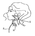
以下本発明を実施形態の図面に基づいて説明する。図1は美顔器の使用状態を示す斜視図であって、使用者が手先Hにてスプレー本体Sの握手部Saを保持している。図2はスプレー本体S、直立型ボンベ収納ボックスX、可撓性ホースPを収納箱Yに夫々収納した状態を示している。
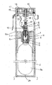
而して、図3は、直立型ボンベ収納ボックスXの内部構造を示す断面図であって、上側筒体1に装填された炭酸ガス供給用ボンベBの食出し部Baを下側筒体2に収納した状態を示している。
The present invention will be described below based on the drawings of the embodiments. FIG. 1 is a perspective view showing a use state of the facial device, and the user holds the handshake part Sa of the spray body S with the hand H. FIG. FIG. 2 shows a state in which the spray body S, the upright cylinder storage box X, and the flexible hose P are stored in the storage box Y, respectively.
Thus, FIG. 3 is a cross-sectional view showing the internal structure of the upright cylinder storage box X, in which the feeding portion Ba of the carbon dioxide gas supply cylinder B loaded in the
具体的には炭酸ガス供給用ボンベBの上端噴出口頭部3に形成されたネジ4を上側筒体1のソケット部5のネジ孔6に捻じ込む。
このソケット部5は上側筒体1の内筒7に装備されており、内筒7は上側筒体1の下開口1aより挿入されて圧入装備され、一体化される。
従って、炭酸ガス供給用ボンベBの上端噴出口頭部3は隠蔽されて外部に触れない状態で該炭酸ガス供給用ボンベBは図3に示す如く、食出し部Baを下側筒体2に収納され、食出し部Baが下側筒体2の底部2aから浮いた状態で装填される。
Specifically, the screw 4 formed on the upper end jet outlet head 3 of the carbon dioxide gas supply cylinder B is screwed into the screw hole 6 of the
The
Accordingly, the upper end jet outlet head 3 of the carbon dioxide supply cylinder B is concealed so as not to touch the outside. Then, the feeding portion Ba is loaded in a state where it floats from the
ソケット部5のネジ孔6には炭酸ガス供給用ボンベBの上端噴出口頭部3の上部に対峙してノズル部8が螺着されている。
A
このノズル部8は、噴出用管9を備えており、この噴出用管9が炭酸ガス供給用ボンベBを捻じ込んだ際、その噴出口頭部3の封印膜3aに貫通し、炭酸ガス供給用ボンベからの噴出ガスを噴出用管9、内孔10、ノズル11に亘ってガス流通路を形成する。
而して、ノズル部8の内孔10には上下動する弁杆12を挿通しており、常に第2バネ13にて上方向に弾圧されており、この弁杆12の上下動によってノズル11の開閉を行う。
The
Thus, a
上側筒体1の上部面1bには一方向および反対方向に水平回転する様、炭酸ガス噴出調整用の円形調整用摘子14が位置しており、該円形調整用摘子14の内側面には雌ネジ15を形成し、上側筒体1の上部面1bに、該上側筒体1の外径より小径のボス16を直立させ、該ボス16の外周に雄ネジ17を形成して、円形調整用摘子14の雌ネジ15と螺合し、該円形調整用摘子14は、その回転によって上下動する。
円形調整用摘子14からは押圧杆18が垂下しており、その下端が弁杆12の上端に当接しており、円形調整用摘子14は第1バネ19にて常に上方向に弾圧されている。
勿論、第1バネ19と第2バネ13のバネ圧力は、その機能目的から第1バネ19を強くしている。
On the upper surface 1 b of the
A
Of course, the spring pressure of the first spring 19 and the
而して、円形調整用摘子14の雌ネジ15と上側筒体1の雄ネジ17とは螺合、即ち、円形調整用摘子14の雌ネジ15の回転には、少なくともギャップ(空隙)を要し、そのギャップによって弁杆12と押圧杆18との接圧がバラ付くことを考慮し、ガス漏れが生じない様に、常に押圧杆18が弁杆12を弾圧させることとしている。
これは、前記ソケット部5のネジ孔6に炭酸ガス供給用ボンベBの上端噴出口頭部3との螺着との文言を敢えて異にしている所以である。
而して図4は、スプレー本体Sの具体例を示し、縦方向に分割された前後カバーSxより成っている。
而して、ボンベ収納ボックスXの側面Xaから導き出された可撓性ホースPが握手部Saの内部Sbに引込まれ、ガスケット20にと接続される。
Thus, the
This is because the wording of screwing the screw hole 6 of the
Thus, FIG. 4 shows a specific example of the spray body S, which is composed of front and rear covers Sx divided in the vertical direction.
Thus, the flexible hose P led out from the side surface Xa of the cylinder storage box X is drawn into the inside Sb of the handshake part Sa and connected to the
可撓性ホースPは、引込口金21に接続され、更に中継用パイプPaを介してガスケット20に接続される。
このガスケット20は、弁機構20aを有し、スプレー本体Sに反転自在に軸支持された操作部22にて弁機構20aを動作させ、中継用パイプPaからの炭酸ガスの送出、停止を操作する。
尚、操作部22は軸23にて支持され、軸23に備えられたコイルバネ24にて矢印aの方向に付勢されており、操作部22を指先にて引くことによって、矢印aと反対方向に反転させ、操作部22の下縁22aが弁機構20aの弁杆20bを押し下げ、炭酸ガスが送出される。
The flexible hose P is connected to the lead-in
This
The
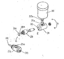
更に弁機構20aの送出口20cには送出用パイプPbの一端が接続されており、他端がガス噴出用ヘッド部25に接続されており、先端ノズル26から操作部22の操作によって炭酸ガスが噴出することとなり、ガス噴出用ヘッド部25は、図5に示す如く送出用パイプPbがガス噴出用細孔27に接続されている。
而して、ガス噴出用ヘッド部25の側面にはガス噴出方向Rに対し直交して突出する第1継手部28の基部28aがネジ孔25aに螺着しており、該第1継手部28の内孔29とガス噴出用ヘッド部25のガス流通内孔30とを連通させている。この第1継手部28は軸状に形成され、その先端には第2継手部31が挿入されて回動自在に装着されており、第2継手部31の内孔32と該第1継手28の内孔29とが連通している。
Further, one end of a delivery pipe Pb is connected to the delivery port 20c of the
Thus, a base portion 28a of the first
第2継手部31には直交、即ちガス噴出方向Rに対し平行して矢印aに示す如く、一定角度回動自在に化粧水収納カップ33を装備している。
具体的には、第2継手部31のネジ孔31aに化粧水収納カップ33の送出口33aを螺着し、化粧水収納カップ33の化粧水送出口33aを前記第2継手部31の内孔31b、第1継手部28の内孔28a、ガス噴出用ヘッド部25のガス流通内孔30にと夫々に亘って連通させている。
これら第1継手部28、第2継手部31にて回動機構部Zを構成し、回動機構部Zには適宜パッキン34、35、36が配されている。
The second
Specifically, the
The first
而して、スプレー本体Sを所望の角度に傾けて操作した場合、仮に化粧水収納カップ33内の化粧水残存量が少ないと気づけば、その化粧水収納カップ33を適宜回動して、化粧水と炭酸ガスとを適正に混合して噴出することができる。
Thus, when the spray body S is operated at a desired angle, if the remaining amount of the lotion in the
図7は異なる実施例を示し、ガス噴出用ヘッド部25の前部に化粧水収納カップ33を位置させ、而もガス噴出方向Rに対し直交する様、化粧水送出口33aを近接して対峙させ、操作部22を押圧操作すればガス噴出によって、化粧水収納カップ33内の化粧水を引き寄せる形式(吸い上げ形式)としている。
而して、化粧水収納カップ33はガス噴出用ヘッド部25の近傍に回動自在に装備されたホルダー37によって保持されており、先端ノズル26と一定間隔状態を維持しつつ化粧水収納カップ33が回動することとしている。
即ち、炭酸ガスとの混合化粧水を最終的に腕、足、身体の肌面へ霧状に噴射すればよいのであって、特に限定するものではない。
FIG. 7 shows a different embodiment, in which a
Thus, the
That is, there is no particular limitation as long as the mixed lotion with carbon dioxide gas is finally sprayed in the form of a mist onto the skin surfaces of the arms, legs and body.
S スプレー本体
Sa 握手部
P 可撓性ホース
B 炭酸ガス供給用ボンベ
X 直立型ボンベ収納ボックス
Z 回動機構部
1 上側筒体
2 下側筒体
14 円形調整用摘子
25 ガス噴出用ヘッド部
26 先端ノズル
28 第1継手部
29 内孔
30 ガス流通内孔
31 第2継手部
32 内孔
33 化粧水収納カップ
DESCRIPTION OF SYMBOLS S Spray body Sa Handshake part P Flexible hose B Carbon dioxide supply cylinder X Upright cylinder storage box Z
Claims (4)
前記スプレー本体は、
(1)ボンベ収納ボックスから導き出した可撓性ホースを引込む握手部と、
(2)該握手部内を経た炭酸ガスを流入すると共に、先端ノズルから炭酸ガスを噴出するガス噴出用ヘッド部と、
(3)該ガス噴出用ヘッド部の近傍に装備されると共に、炭酸ガスの噴出に伴い収納された化粧水が炭酸混合化粧水として霧状に噴射される化粧水収納カップと、
(4)該化粧水収納カップの送出口とガス噴出用ヘッド部の先端ノズルとの間隔を、一定間隔状態を維持しつつ化粧水収納カップを回動させる回動機構部と
(5)で成したことを特徴とする美顔器における炭酸ガス噴出用スプレー。 A predetermined amount of lotion is stored in a cup, and carbon dioxide gas guided from a carbon dioxide supply cylinder through a flexible hose is ejected from the tip ejection nozzle of the spray body, together with the lotion in the cup. In a facial device that sprays mixed lotion in the form of a mist,
The spray body is
(1) A handshake part that draws in the flexible hose led out from the cylinder storage box;
(2) a gas ejection head portion for injecting carbon dioxide gas that has passed through the handshake portion and ejecting carbon dioxide gas from the tip nozzle;
(3) A lotion storage cup that is provided in the vicinity of the gas jetting head portion and in which the lotion stored in association with the jet of carbon dioxide gas is sprayed in the form of a mist as a carbonated mixed lotion;
(4) (5) a rotating mechanism for rotating the lotion storage cup while maintaining a constant interval between the outlet of the lotion storage cup and the tip nozzle of the gas ejection head unit; A spray for blowing carbon dioxide in a facial device characterized by the above.
Priority Applications (1)
| Application Number | Priority Date | Filing Date | Title |
|---|---|---|---|
| JP2013076020A JP2014200311A (en) | 2013-04-01 | 2013-04-01 | Carbon dioxide gas ejection spray in facial equipment |
Applications Claiming Priority (1)
| Application Number | Priority Date | Filing Date | Title |
|---|---|---|---|
| JP2013076020A JP2014200311A (en) | 2013-04-01 | 2013-04-01 | Carbon dioxide gas ejection spray in facial equipment |
Publications (1)
| Publication Number | Publication Date |
|---|---|
| JP2014200311A true JP2014200311A (en) | 2014-10-27 |
Family
ID=52351331
Family Applications (1)
| Application Number | Title | Priority Date | Filing Date |
|---|---|---|---|
| JP2013076020A Pending JP2014200311A (en) | 2013-04-01 | 2013-04-01 | Carbon dioxide gas ejection spray in facial equipment |
Country Status (1)
| Country | Link |
|---|---|
| JP (1) | JP2014200311A (en) |
-
2013
- 2013-04-01 JP JP2013076020A patent/JP2014200311A/en active Pending
Similar Documents
| Publication | Publication Date | Title |
|---|---|---|
| KR101630356B1 (en) | Portable Automatic Mist Apparatus | |
| CA2696224A1 (en) | Wipes dispenser | |
| JP6250199B2 (en) | airbrush | |
| US20150147473A1 (en) | Airbrush effect system | |
| JP4871937B2 (en) | Facial massager | |
| JP2015224075A (en) | Pump type liquid discharger | |
| JP2014200311A (en) | Carbon dioxide gas ejection spray in facial equipment | |
| JP5732099B2 (en) | Facial massager | |
| JP2013233957A (en) | Anti-liquid-leakage structure in spray device | |
| CN210883370U (en) | Dry powder sprayer | |
| JP2014200310A (en) | Facial equipment storage box | |
| CN217448631U (en) | Atomizer and electron oral cavity atomizer | |
| KR200468344Y1 (en) | Pump head structure having rotating nozzle variable effusion direction | |
| US8893985B2 (en) | Pump fragrance device with a carrier agent | |
| CN202591007U (en) | Electric spray gun | |
| JP2013233958A (en) | Attachment structure of gas container in spray device | |
| JP3175446U (en) | Personal care spray | |
| US20150001317A1 (en) | Water absorbing apparatus for water spray container | |
| JP2012250427A (en) | Instrument for wetting fingertip | |
| CN210875885U (en) | Fragrant atmosphere machine and fragrant atmosphere device that can screen atomized particles and prevent oxidation | |
| CN211535571U (en) | Beauty oxygen injection spraying instrument | |
| CN210809684U (en) | Novel perfume pump device | |
| CN208116342U (en) | Clean inhalator jar | |
| JP3167653U (en) | Edible oil injector | |
| JP5606801B2 (en) | Trigger type bubble jet |