JP2014200310A - Facial equipment storage box - Google Patents
Facial equipment storage box Download PDFInfo
- Publication number
- JP2014200310A JP2014200310A JP2013076019A JP2013076019A JP2014200310A JP 2014200310 A JP2014200310 A JP 2014200310A JP 2013076019 A JP2013076019 A JP 2013076019A JP 2013076019 A JP2013076019 A JP 2013076019A JP 2014200310 A JP2014200310 A JP 2014200310A
- Authority
- JP
- Japan
- Prior art keywords
- storage box
- synthetic resin
- cylinder
- carbon dioxide
- storing
- Prior art date
- Legal status (The legal status is an assumption and is not a legal conclusion. Google has not performed a legal analysis and makes no representation as to the accuracy of the status listed.)
- Pending
Links
Images


Abstract
Description
本発明は化粧水と炭酸ガスとの混合液を顔肌等に噴霧状に吹き付ける美顔器具を収納する収納箱に関する。 The present invention relates to a storage box for storing a facial device for spraying a liquid mixture of a lotion and carbon dioxide onto a face skin or the like.
一般的に、炭酸成分が皮膚下の毛細血管に作用してこの毛細血管を拡張させる効能を利用し、化粧水と共に混合液を顔肌等に吹き付けると共に、皮脂や汚れ等の残骸物を顔肌から遊離させて取り除き、より若々しく美しい顔肌を指向する社会的ウオンツが顕在化している。
そこで、これらに関連する多くの技術文献1〜4が存在し、炭酸ガスボンベとガス噴出ノズルとを機械的に直結、即ちスプレー本体内にガスボンベを収納し、スプレー本体そのものを手元にて持上げ操作し、混合化粧水をガスと共に噴射させている。
In general, the carbonic acid component acts on the capillaries under the skin to expand the capillaries, and sprays the mixture with skin lotion on the face skin and removes debris such as sebum and dirt. The social wonders that have been removed from the skin and directed towards a more youthful and beautiful facial skin have become apparent.
Therefore, there are many
然しながら、美顔器の使用は主に女性であることから、約300gからの炭酸ガスボンベを含め相応の重さの美顔器を片手で顔面の高さまで持ち上げての使用は、些か現実にそぐわない。
そこで、本願発明者の一人が創作活動の一翼を担って技術文献5に示す美顔器の製品化に結び付け、更には改良を重ね、技術文献6、7に示す美顔器を創出した。
これらは、炭酸ガスボンベを収納するボックスと手元にて操作するスプレーとを分離して両者を可撓性ホースにて接続すると共に、炭酸ガスボンベの収納ボックスは化粧台等に直立着座させたままで、スプレーを軽快に操作することとしている。
However, since the use of a facial device is mainly a woman, it is slightly unsuitable to lift a facial device of a suitable weight including a carbon dioxide cylinder from about 300 g to the height of the face with one hand.
Therefore, one of the inventors of the present application took part of the creative activity, linked to the commercialization of the facial device shown in
They separate the box that stores the carbon dioxide cylinder and the spray that is operated at hand and connect them together with a flexible hose, while the storage box for the carbon dioxide cylinder remains sprayed on a dressing table, etc. It is supposed to be operated lightly.
而して、更なる商品の利便性を探求すると共に、企図することとし、炭酸ガスボンベの収納ボックスを化粧台等に直立着座させ、スプレーを持上げて操作することから、視線が鏡面に集中し、炭酸ガスボンベの収納ボックスの存在がおろそかになり、スプレーの操作によって可撓性ホースが引っ張られ、炭酸ガスボンベの収納ボックスが縦長であることと相俟って、横倒れする恐れがある。
そこで、炭酸ガスボンベの収納ボックスを横向きに倒して使用されることも危惧され、且つガス噴出に支障が伴う恐れもある。
更に、使用後の保管についても、縦長状の炭酸ガスボンベの収納ボックスを横向きに倒したまま放置する恐れもあり、その後の使用において支障を来すことも否定できない。
Thus, in addition to exploring the convenience of further products, we intend to contemplate, sit the carbon dioxide cylinder storage box upright on a dressing table, etc., and operate by lifting the spray, so the line of sight concentrates on the mirror surface, The existence of the storage box of the carbon dioxide cylinder is neglected, and the flexible hose is pulled by the operation of the spray, and there is a possibility that the storage box of the carbon dioxide cylinder may be laid down in combination with the vertically long storage box.
Therefore, it is feared that the storage box of the carbon dioxide cylinder is tilted sideways and used, and there is a risk that the gas ejection may be hindered.
Furthermore, in storage after use, there is also a risk that the vertically long carbon dioxide gas cylinder storage box may be left sideways, and there is no denying that it will cause problems in subsequent use.
本発明は、炭酸ガスボンベを収納するボックスと、手元にて操作するスプレーとを分離して両者を可撓性ホースにて接続することによってスプレーを持上げて操作することから、可撓性ホースが引っ張られ、炭酸ガスボンベの収納ボックスが縦長であることと相俟って、横倒れする恐れがあること、更には炭酸ガスボンベの収納ボックスを横向きに倒して使用されることからガス噴出に支障が伴う恐れもあること、並びに使用後の保管についても、縦長状の炭酸ガスボンベの収納ボックスを横向きに倒したまま放置する恐れもあり、その後の使用に支障を来すことへの課題を解決する。 Since the present invention operates by lifting the spray by separating the box for storing the carbon dioxide cylinder and the spray to be operated at hand and connecting them with the flexible hose, the flexible hose is pulled. Coupled with the fact that the storage box of the carbon dioxide cylinder is vertically long, there is a risk of falling sideways, and furthermore, the use of the carbon dioxide cylinder storage box tilted sideways may cause problems in gas ejection. In addition, there is a possibility that the storage box of the vertically long carbon dioxide gas cylinder may be left sideways while being stored after use, which solves the problem of hindering subsequent use.
本発明は、
(1)所定量の化粧水をカップに収納し、且つ炭酸ガス供給用ボンベから可撓性ホースを介して導かれた炭酸ガスをスプレー本体の先端噴出ノズルから噴出させて前記カップ内の化粧水と共に、炭酸混合化粧水を霧状に噴射する様にした美顔器具に於いて、
(2)合成樹脂製の上開口の下側筐体と、
(3)この下側筐体の開口上縁に上縁が着座すると共に、該下側筐体に嵌合される合成樹脂製の中間筐体と、
(4)更に該中間筐体の上部に空間を形成する様、開蓋自在に装着される合成樹脂製の上側筐体とで成し、
(5)前記合成樹脂製の中間筐体には、前記直立型炭酸ガス供給用ボンベを収納すると共に、ガス噴出を操作する円形回転調整用摘子を上部に備えるボンベ収納ボックスを直立状に収納載置する上開口の第1縦状収納窪部と、
(6)前記スプレー本体を収納する上開口の第2縦状収納窪部と、
(7)該スプレー本体と前記直立型ボンベ収納ボックスとを接続する可撓性ホースをカール状に収納する上開口の第3縦状収納窪部とであって、
(8)第1、第2、第3縦状収納窪部は互いに連通していることを特徴とするものである。
The present invention
(1) A predetermined amount of lotion is stored in a cup, and carbon dioxide introduced from a carbon dioxide supply cylinder through a flexible hose is ejected from a tip ejection nozzle of a spray main body, thereby the lotion in the cup. At the same time, in a facial device that sprays carbonated lotion in the form of a mist,
(2) a lower housing of an upper opening made of synthetic resin;
(3) A synthetic resin intermediate housing that is fitted to the lower housing, with an upper edge seated on the upper edge of the opening of the lower housing,
(4) Further, it is composed of an upper casing made of a synthetic resin that can be freely opened to form a space above the intermediate casing,
(5) The intermediate housing made of synthetic resin accommodates the upright carbon dioxide supply cylinder, and also accommodates the cylinder storage box having a circular rotation adjusting knob for operating gas ejection in an upright state. A first vertical storage recess of the upper opening to be placed;
(6) a second vertical storage recess in the upper opening for storing the spray body;
(7) a third vertical storage recess having an upper opening for storing the flexible hose connecting the spray body and the upright cylinder storage box in a curled shape;
(8) The first, second, and third vertical storage recesses communicate with each other.
更に本発明は、
(1)所定量の化粧水をカップに収納し、且つ炭酸ガス供給用ボンベから可撓 性ホースを介して導かれた炭酸ガスをスプレー本体の先端噴出ノズルから噴出させて前記カップ内の化粧水と共に、炭酸混合化粧水を霧状に噴射する様にした美顔器具に於いて、
(2)合成樹脂製の下側筐体と、
(3)この下側筐体の開口上縁に上縁が着座すると共に、該下側筐体に嵌合される合成樹脂製の中間筐体と、
(4)更に該中間筐体の上部に空間を形成する様、開蓋自在に装着される合成樹脂製の上側筐体とで成し、
(5)前記合成樹脂製の中間筐体には、前記直立型炭酸ガス供給用ボンベを収納すると共に、ガス噴出を操作する円形回転調整用摘子を上部に備えるボンベ収納ボックスを直立状に収納載置する上開口の第1縦状収納窪部と、
(6)前記スプレー本体を収納する上開口の第2縦状収納窪部と、
(7)該スプレー本体と前記直立型ボンベ収納ボックスとを接続する可撓性ホースをカール状に収納する上開口の第3縦状収納窪部とであって、
(8)前記スプレー本体を収納する上開口の第2縦状収納窪部を中央に配し、
(9)ボンベ収納ボックスを収納する上開口の第1縦状収納窪部を一方側に 配し、
(10)可撓性ホースをカール状に収納する上開口の第3縦状収納窪部を他方側に配して夫々の縦状収納窪部を互いに連通していることを特徴とするものである。
Furthermore, the present invention provides
(1) A predetermined amount of lotion is stored in a cup, and carbon dioxide introduced from a carbon dioxide supply cylinder through a flexible hose is ejected from a tip ejection nozzle of a spray body to cause the lotion in the cup. At the same time, in a facial device that sprays carbonated lotion in the form of a mist,
(2) a lower housing made of synthetic resin;
(3) A synthetic resin intermediate housing that is fitted to the lower housing, with an upper edge seated on the upper edge of the opening of the lower housing,
(4) Further, it is composed of an upper casing made of a synthetic resin that can be freely opened to form a space above the intermediate casing,
(5) The intermediate housing made of synthetic resin accommodates the upright carbon dioxide supply cylinder, and also accommodates the cylinder storage box having a circular rotation adjusting knob for operating gas ejection in an upright state. A first vertical storage recess of the upper opening to be placed;
(6) a second vertical storage recess in the upper opening for storing the spray body;
(7) a third vertical storage recess having an upper opening for storing the flexible hose connecting the spray body and the upright cylinder storage box in a curled shape;
(8) The second vertical storage recess of the upper opening that stores the spray main body is arranged in the center,
(9) The first vertical storage recess of the upper opening for storing the cylinder storage box is arranged on one side,
(10) The third vertical storage recess of the upper opening that stores the flexible hose in a curled shape is arranged on the other side, and the respective vertical storage recesses communicate with each other. is there.
更に本発明は、合成樹脂製の上側筐体は、合成樹脂製中間筐体第1、第2、第3縦状収納窪部に収納された直立型ボンベ収納ボックス、スプレー本体、カール状に収納された可撓性ホースが可視できる様、可透性合成樹脂製にて形成したことを特徴とするものである。 Further, according to the present invention, the upper casing made of synthetic resin is stored in an upright cylinder storage box, a spray main body, and a curl shape stored in the first, second, and third vertical storage recesses of the synthetic resin intermediate casing. The flexible hose is made of a permeable synthetic resin so that it can be seen.
又本発明は、合成樹脂製の中間筐体は、上縁を下側筐体の開口上縁に着座させると共に、該下側筐体の底部から挿入された止めネジが螺合して下側筐体と組合さることを特徴とするものである。 Further, according to the present invention, the synthetic resin intermediate housing has the upper edge seated on the upper edge of the opening of the lower housing, and the set screw inserted from the bottom of the lower housing is screwed into the lower housing. It is characterized by being combined with a housing.
又本発明は、下側筐体の開口上縁は、側壁のほぼ中間位置に薄肉部を形成し、この薄肉部を外方向から押圧することによって内側に反ると共に、中間筐体の側壁との間に空隙を形成する様にしたことを特徴とするものである。 Further, according to the present invention, the upper edge of the opening of the lower casing is formed with a thin portion at a substantially middle position of the side wall, and the thin portion is warped inward by pressing the thin portion from the outside. A void is formed between the two.
(1)請求項1により、炭酸ガスボンベ収納ボックスは合成樹脂製の下側筐体に収納保持されているので、スプレー操作時に可撓性ホースの引張力に追随して該炭酸ガスボンベ収納ボックスが横倒れすることがなく、スプレー操作を軽快に行える。
更に、美顔器具を使用した後、スプレー本体についてもカール状にした可撓性ホースと共に、夫々の第1縦状収納窪部、第2縦状収納窪部、第3縦状収納窪部にと分離して収納され、雑然と収納されることにより次回の使用時に可撓性ホースと絡まった状態から無理に解そうとして、可撓性ホースが抜け外れることもなく、旅行等に際して持ち運びできる利便性がある。
(1) According to
In addition, after using the facial device, the spray body has a curled flexible hose, and the first vertical storage recess, the second vertical storage recess, and the third vertical storage recess. Convenience that can be carried away when traveling, etc. without being pulled out, trying to forcibly unscrew the flexible hose from being tangled with the flexible hose at the next use by being stored separately and stored There is.
請求項2により、スプレー本体を収納する第2縦状収納窪部を中心として一方側の第1縦状収納窪部にはボンベ収納ボックスが、他方側の第3縦状収納窪部にはカール状に可撓性ホースが夫々収納しているので、両者を整然と区分して整理収納することができる。
According to
請求項3により、上側筐体から中間筐体の第1、第2、第3縦状収納窪部に収納された直立型ボンベ収納ボックス、スプレー本体、カール状に収納された可撓性ホースが可視できる。 According to claim 3, an upright cylinder storage box, a spray main body, and a flexible hose stored in a curl shape stored in the first, second and third vertical storage recesses of the intermediate casing from the upper casing. Visible.
請求項4により、合成樹脂製の中間筐体と下側筐体とは止めネジにて強固に結着しており、直立型ボンベ収納ボックス、スプレー本体、可撓性ホースの重みで中間筐体が抜け外れることもなく、不測の事態を免れる。
According to
請求項5により、中間筐体と下側筐体とが強固に密着結合している場合においても、下側筐体の薄肉部を外方向から押圧すれば、中間筐体の側壁との間に空隙、即ち両筐体の密着が解かれ、容易に外すことができる。 According to the fifth aspect, even when the intermediate casing and the lower casing are tightly bonded, if the thin portion of the lower casing is pressed from the outside, the intermediate casing and the lower casing are spaced from the side walls of the intermediate casing. The gap, that is, the close contact between both housings is released, and can be easily removed.
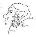
以下本発明を実施形態の図面に基づいて説明する。図1は美顔器の使用状態を示す斜視図であって、使用者が手先Hにてスプレー本体Sの握手部Saを保持している。図2は美顔器具Wの全体を示す斜視図であって、直立型ボンベ収納ボックスXを上下側筒体1、2にて構成しており、ボンベ収納ボックスXの側面Xaから導き出された可撓性ホースPとスプレー本体Sとが接続されている。図3は、直立型ボンベ収納ボックスXの内部構造を示す断面図であって、上側筒体1に装填された炭酸ガス供給用ボンベBの食出し部Baを下側筒体2に収納した状態を示している。
The present invention will be described below based on the drawings of the embodiments. FIG. 1 is a perspective view showing a use state of the facial device, and the user holds the handshake part Sa of the spray body S with the hand H. FIG. FIG. 2 is a perspective view showing the whole facial beauty instrument W, wherein the upright cylinder storage box X is composed of the upper and
具体的には炭酸ガス供給用ボンベBの上端噴出口頭部3に形成されたネジ4を上側筒体1のソケット部5のネジ孔6に捻じ込む。
このソケット部5は上側筒体1の内筒7に装備されており、内筒7は上側筒体1の下開口1aより挿入されて圧入装備され、一体化される。
従って、炭酸ガス供給用ボンベBの上端噴出口頭部3は隠蔽されて外部に触れない状態で、該炭酸ガス供給用ボンベBは図3に示す如く、食出し部Baを下側筒体2に収納されており、その下側筒体2は有底としているので炭酸ガス供給用ボンベBは底部2aにて覆われた状態にて吊り下げられ、食出し部Baが下側筒体2の底部2aから浮いた状態で装填される。
Specifically, the
The
Therefore, the upper end jet outlet head 3 of the carbon dioxide gas supply cylinder B is concealed so as not to touch the outside, and the carbon dioxide supply cylinder B has the feeding portion Ba in the lower
ソケット部5のネジ孔6には炭酸ガス供給用ボンベBの上端噴出口頭部3の上部に対峙してノズル部8が螺着されている。
A
このノズル部8は、噴出用管9を備えており、この噴出用管9が炭酸ガス供給用ボンベBを捻じ込んだ際、その噴出口頭部3の封印膜3aに貫通し、炭酸ガス供給用ボンベからの噴出ガスを噴出用管9、内孔10、ノズル11に亘ってガス流通路を形成する。
而して、ノズル部8の内孔10には上下動する弁杆12を挿通しており、常に第2バネ13にて上方向に弾圧されており、この弁杆12の上下動によってノズル11の開閉を行う。
The
Thus, a
上側筒体1の上部面1bには一方向および反対方向に水平回転する様、炭酸ガス噴出調整用の円形調整用摘子14が位置しており、該円形調整用摘子14の内側面には雌ネジ15を形成し、上側筒体1の上部面1bに、該上側筒体1の外径より小径のボス16を直立させ、該ボス16の外周に雄ネジ17を形成して、円形調整用摘子14の雌ネジ15と螺合し、該円形調整用摘子14は、その回転によって上下動する。
円形調整用摘子14からは押圧杆18が垂下しており、その下端が弁杆12の上端に当接しており、円形調整用摘子13は第1バネ19にて常に上方向に弾圧されている。
勿論、第1バネ19と第2バネ13のバネ圧力は、その機能目的から第1バネ19を強くしている。
On the upper surface 1 b of the
A
Of course, the spring pressure of the
而して、円形調整用摘子14の雌ネジ15と上側筒体1の雄ネジ17とは螺合、即ち、円形調整用摘子14の雌ネジ15の回転には、少なくともギャップ(空隙)を要し、そのギャップによって弁杆12と押圧杆18との接圧がバラ付くことを考慮し、ガス漏れが生じない様に、常に押圧杆18が弁杆12を弾圧させることとしている。
これは、前記ソケット部5のネジ孔6に炭酸ガス供給用ボンベBの上端噴出口頭部3との螺着との文言を敢えて異にしている所以である。
而して図4は、スプレー本体Sの具体例を示し、ボンベ収納ボックスXの側面Xaから導き出された可撓性ホースPが握手部Saの内部Sbに引込まれ、ガスケット20にと接続される。
Thus, the
This is because the wording of screwing the
4 shows a specific example of the spray main body S, and the flexible hose P led out from the side surface Xa of the cylinder storage box X is drawn into the inside Sb of the handshake part Sa and connected to the
可撓性ホースPは、引込口金21に接続され、更に中継用パイプPaを介してガスケット20に接続される。
このガスケット20は、弁機構20aを有し、スプレー本体Sに反転自在に軸支持された操作部22にて弁機構20aを動作させ、中継用パイプPaからの炭酸ガスの送出、停止を操作する。
尚、操作部22は、軸23にて支持され、軸23に備えられたコイルバネ24にて矢印aの方向に付勢されており、操作部22を指先にて引くことによって、矢印aと反対方向に反転させ、操作部22の下縁22aが弁機構20aの弁杆20bを押し下げ、炭酸ガスが送出される。
The flexible hose P is connected to the lead-
This
The
更に弁機構20aの送出口20cには送出用パイプPbの一端が接続されており、他端がガス噴出用ヘッド部25に接続されており、先端ノズル26から操作部22の操作によって炭酸ガスが噴出することとなる。
このガス噴出用ヘッド部25には化粧水を収納するカップ27を、導管28を介して一定角度回動する様、軸支持しており、仮にスプレー本体Sを所望の角度で操作した場合においても、カップ27内の化粧水を常に最適な状態に修正追随させ、炭酸ガスのみが噴出することがない。
Further, one end of a delivery pipe Pb is connected to the
The gas
而して、この混合化粧水の噴出は、ガス噴出用ヘッド部25の内部において化粧水と混合させているが、勿論、先端ノズル26の近傍にカップ27を位置させ、炭酸ガスの噴出に伴い、化粧水を引き寄せる形式としてもよく、最終的に腕、足、身体の肌面への炭酸混合化粧水を霧状に噴射すればよいのであって、特に限定するものではない。
勿論、上記実施例の美顔器具Wは一実施例に過ぎず、特に限定するものではない。
Thus, the mixed skin lotion is mixed with the skin lotion inside the gas
Of course, the facial beauty apparatus W of the said Example is only one Example, and is not specifically limited.
図5は上記構成された美顔器具Wを収納箱に収納した状態をと示す斜視図であって、下側筐体29、中間筐体30、上側筐体31にて構成されており、下側筐体29は上開口29aに形成され、且つ中間筐体30は下開口30aに形成、更に上側筐体31は下開口31aにと夫々合成樹脂にて成形されており、上側筐体31は可透性合成樹脂製となっており、図7に示す如く、下側筐体29の開口上縁29bに中間筐体30の開口下縁30bが着座し、中間筐体30の天板30cの周縁30dに上側筐体31の開口下縁31bが嵌合し、開蓋自在に装着される。
而して、中間筐体30の天板30cには上側筐体31を外した状態にて円形調整用摘子14が回転操作できる様、直立型ボンベ収納ボックスXを上開口32aの第1縦状収納窪部32に収納している。
FIG. 5 is a perspective view illustrating a state in which the facial beauty instrument W configured as described above is stored in a storage box, which includes a
Thus, the upright cylinder storage box X is arranged on the
更に中間筐体30の天板30cにはスプレー本体Sを収納する上開口33aの第2縦状収納窪部33を形成している。
又、中間筐体30の天板30cには可撓性ホースPをカール状にして収納する上開口34aの第3の縦状収納窪部34を形成しており、各々の第1、第2、第3縦状収納窪部32、33、34は互いに連通し、この連通窪部35に直立型ボンベ収納ボックスXからスプレー本体S、更にはカール状に収納される可撓性ホースPの通路となっている。
勿論、この第3縦状収納窪部34には炭酸ガス供給用ボンベBを直立型ボンベ収納ボックスXに装填していない状態、即ち製品出荷状態にて収納することとしてもよく、又、装填した後の予備用の炭酸ガス供給用ボンベBの収納スペースとしても利用できる。
Further, the
Further, the
Of course, the carbon dioxide gas supply cylinder B may be stored in the third
各々の第1、第2、第3縦状収納窪部32、33、34の配列は、スプレー本体Sを収納する第2縦状収納窪部33を中央に、且つ第1、第3縦状収納窪部32、34を両側に配して、可撓性ホースPが整然と区分して整理収納され、錯綜して無理に解こうとして可撓性ホースPが直立型ボンベ収納ボックスX或いは、スプレー本体Sから抜け外れることがない。
これらの状態は、上側筐体31が可透性合成樹脂製のため内部の収納状態を確認できる。
中間筐体30の底部30dには下側筐体29の底部29cから挿入された止め
ネジ36が螺合し、下側筐体29とを組合せる。
Each of the first, second, and third vertical storage recesses 32, 33, and 34 is arranged with the second
In these states, since the
A
下側筐体29の開口上縁29bは、その側壁29dのほぼ中間位置に薄肉部29eを形成し、下側筐体29を外す際に、薄肉部29eを外方向から押圧すれば、薄肉部29eが内側に反ると共に、中間筐体30の側壁30eとの間に空隙が形成されて両者の密着は解放されて、中間筐体30を簡単に抜け外すことができる。
下側筐体29には左右の止め具37によってコ字型吊手38が反転自在に取付られており、収納した美顔器具Wと共に、収納箱を持ち運ぶことができる。
The opening
A
S スプレー本体
Sa 握手部
W 美顔器具
X 直立型ボンベ収納ボックス
P 可撓性ホース
B 炭酸ガス供給用ボンベ
14 円形調整用摘子
27 カップ
29 下側筐体
30 中間筐体
31 上側筐体
32 第1縦状収納窪部
33 第2縦状収納窪部
34 第3縦状収納窪部
35 連通窪部
S Spray main body Sa Handshake part W Facial instrument X Upright cylinder storage box P Flexible hose B Carbon
Claims (5)
(2)合成樹脂製の上開口の下側筐体と、
(3)この下側筐体の開口上縁に上縁が着座すると共に、該下側筐体に嵌合される合成樹脂製の中間筐体と、
(4)更に該中間筐体の上部に空間を形成する様、開蓋自在に装着される合成樹脂製の上側筐体とで成し、
(5)前記合成樹脂製の中間筐体には、前記直立型炭酸ガス供給用ボンベを収納すると共に、ガス噴出を操作する円形回転調整用摘子を上部に備えるボンベ収納ボックスを直立状に収納載置する上開口の第1縦状収納窪部と、
(6)前記スプレー本体を収納する上開口の第2縦状収納窪部と、
(7)該スプレー本体と前記直立型ボンベ収納ボックスとを接続する可撓性ホースをカール状に収納する上開口の第3縦状収納窪部とであって、
(8)第1、第2、第3縦状収納窪部は互いに連通していることを特徴とする美顔器具収納箱。 (1) A predetermined amount of lotion is stored in a cup, and carbon dioxide introduced from a carbon dioxide supply cylinder through a flexible hose is ejected from a tip ejection nozzle of a spray main body, thereby the lotion in the cup. At the same time, in a facial device that sprays carbonated lotion in the form of a mist,
(2) a lower housing of an upper opening made of synthetic resin;
(3) A synthetic resin intermediate housing that is fitted to the lower housing, with an upper edge seated on the upper edge of the opening of the lower housing,
(4) Further, it is composed of an upper casing made of a synthetic resin that can be freely opened to form a space above the intermediate casing,
(5) The intermediate housing made of synthetic resin accommodates the upright carbon dioxide supply cylinder, and also accommodates the cylinder storage box having a circular rotation adjusting knob for operating gas ejection in an upright state. A first vertical storage recess of the upper opening to be placed;
(6) a second vertical storage recess in the upper opening for storing the spray body;
(7) a third vertical storage recess having an upper opening for storing the flexible hose connecting the spray body and the upright cylinder storage box in a curled shape;
(8) The facial instrument storage box, wherein the first, second, and third vertical storage recesses communicate with each other.
(2)合成樹脂製の下側筐体と、
(3)この下側筐体の開口上縁に上縁が着座すると共に、該下側筐体に嵌合される合成樹脂製の中間筐体と、
(4)更に該中間筐体の上部に空間を形成する様、開蓋自在に装着される合成樹脂製の上側筐体とで成し、
(5)前記合成樹脂製の中間筐体には、前記直立型炭酸ガス供給用ボンベを収納すると共に、ガス噴出を操作する円形回転調整用摘子を上部に備えるボンベ収納ボックスを直立状に収納載置する上開口の第1縦状収納窪部と、
(6)前記スプレー本体を収納する上開口の第2縦状収納窪部と、
(7)該スプレー本体と前記直立型ボンベ収納ボックスとを接続する可撓性ホースをカール状に収納する上開口の第3縦状収納窪部とであって、
(8)前記スプレー本体を収納する上開口の第2縦状収納窪部を中央に配し、
(9)ボンベ収納ボックスを収納する上開口の第1縦状収納窪部を一方側に配し、
(10)可撓性ホースをカール状に収納する上開口の第3縦状収納窪部を他方側に配して夫々の縦状収納窪部を互いに連通していることを特徴とする美顔器具収納箱。 (1) A predetermined amount of lotion is stored in a cup, and carbon dioxide introduced from a carbon dioxide supply cylinder through a flexible hose is ejected from a tip ejection nozzle of a spray main body, thereby the lotion in the cup. At the same time, in a facial device that sprays carbonated lotion in the form of a mist,
(2) a lower housing made of synthetic resin;
(3) A synthetic resin intermediate housing that is fitted to the lower housing, with an upper edge seated on the upper edge of the opening of the lower housing,
(4) Further, it is composed of an upper casing made of a synthetic resin that can be freely opened to form a space above the intermediate casing,
(5) The intermediate housing made of synthetic resin accommodates the upright carbon dioxide supply cylinder, and also accommodates the cylinder storage box having a circular rotation adjusting knob for operating gas ejection in an upright state. A first vertical storage recess of the upper opening to be placed;
(6) a second vertical storage recess in the upper opening for storing the spray body;
(7) a third vertical storage recess having an upper opening for storing the flexible hose connecting the spray body and the upright cylinder storage box in a curled shape;
(8) The second vertical storage recess of the upper opening that stores the spray main body is arranged in the center,
(9) The first vertical storage recess of the upper opening for storing the cylinder storage box is arranged on one side,
(10) A facial device characterized in that a third vertical storage recess having an upper opening for storing the flexible hose in a curled shape is arranged on the other side so that the respective vertical storage recesses communicate with each other. Storage box.
Priority Applications (1)
| Application Number | Priority Date | Filing Date | Title |
|---|---|---|---|
| JP2013076019A JP2014200310A (en) | 2013-04-01 | 2013-04-01 | Facial equipment storage box |
Applications Claiming Priority (1)
| Application Number | Priority Date | Filing Date | Title |
|---|---|---|---|
| JP2013076019A JP2014200310A (en) | 2013-04-01 | 2013-04-01 | Facial equipment storage box |
Publications (1)
| Publication Number | Publication Date |
|---|---|
| JP2014200310A true JP2014200310A (en) | 2014-10-27 |
Family
ID=52351330
Family Applications (1)
| Application Number | Title | Priority Date | Filing Date |
|---|---|---|---|
| JP2013076019A Pending JP2014200310A (en) | 2013-04-01 | 2013-04-01 | Facial equipment storage box |
Country Status (1)
| Country | Link |
|---|---|
| JP (1) | JP2014200310A (en) |
Cited By (2)
| Publication number | Priority date | Publication date | Assignee | Title |
|---|---|---|---|---|
| JP2016175685A (en) * | 2015-03-20 | 2016-10-06 | 株式会社リード | Handle fitting structure of storage case |
| CN106619041A (en) * | 2015-11-04 | 2017-05-10 | 松下知识产权经营株式会社 | Beauty equipment, beauty equipment and beauty methods |
-
2013
- 2013-04-01 JP JP2013076019A patent/JP2014200310A/en active Pending
Cited By (2)
| Publication number | Priority date | Publication date | Assignee | Title |
|---|---|---|---|---|
| JP2016175685A (en) * | 2015-03-20 | 2016-10-06 | 株式会社リード | Handle fitting structure of storage case |
| CN106619041A (en) * | 2015-11-04 | 2017-05-10 | 松下知识产权经营株式会社 | Beauty equipment, beauty equipment and beauty methods |
Similar Documents
| Publication | Publication Date | Title |
|---|---|---|
| CN105246372B (en) | Rotate discharge formula cosmetics containers | |
| US9861135B2 (en) | Atomizer assembly for electronic cigarette and atomizer thereof | |
| AU2014409667B2 (en) | Airbrush | |
| KR20150134792A (en) | Portable Automatic Mist Apparatus | |
| CN204245432U (en) | Prevent the scent flask of child | |
| JP2014200310A (en) | Facial equipment storage box | |
| JP4871937B2 (en) | Facial massager | |
| JP5732099B2 (en) | Facial massager | |
| CN105270769B (en) | Canned beer bubbler | |
| KR101321907B1 (en) | An air freshener spray device for bathroom | |
| CN202642483U (en) | Dry powder sprayer | |
| CN205518332U (en) | Hand -held aerosol dispenser | |
| JP6534298B2 (en) | Sprayer | |
| CN208573375U (en) | Suction pipe cup lid | |
| JP2014200311A (en) | Carbon dioxide gas ejection spray in facial equipment | |
| CN103708091B (en) | The dual spring atomizing pump that a kind of spray effect is good | |
| JP3175446U (en) | Personal care spray | |
| CN208799628U (en) | A kind of moisturizing instrument | |
| CN204428399U (en) | Child health care automatic powder spraying masseur | |
| CN110436059A (en) | A kind of push type dry powder nebulizers | |
| JP2016209639A (en) | Method for spraying carbonic acid-mixed skin lotion | |
| JP3006111U (en) | Carbon dioxide regulator | |
| WO2015024186A1 (en) | Fan | |
| JP5329608B2 (en) | Facial massager | |
| CN209108229U (en) | It is a kind of to have both the beauty instrument host inhaled blackhead and infuse oxygen function |