JP2014197294A - Position identification device and mobile robot having the same - Google Patents
Position identification device and mobile robot having the same Download PDFInfo
- Publication number
- JP2014197294A JP2014197294A JP2013072203A JP2013072203A JP2014197294A JP 2014197294 A JP2014197294 A JP 2014197294A JP 2013072203 A JP2013072203 A JP 2013072203A JP 2013072203 A JP2013072203 A JP 2013072203A JP 2014197294 A JP2014197294 A JP 2014197294A
- Authority
- JP
- Japan
- Prior art keywords
- mobile robot
- distance
- moving body
- area
- identification device
- Prior art date
- Legal status (The legal status is an assumption and is not a legal conclusion. Google has not performed a legal analysis and makes no representation as to the accuracy of the status listed.)
- Pending
Links
- 238000004891 communication Methods 0.000 claims description 5
- 230000007613 environmental effect Effects 0.000 claims description 4
- 238000005259 measurement Methods 0.000 claims description 4
- 230000002093 peripheral effect Effects 0.000 abstract 3
- 238000000034 method Methods 0.000 description 6
- 238000010586 diagram Methods 0.000 description 3
- 238000001514 detection method Methods 0.000 description 1
- 230000001678 irradiating effect Effects 0.000 description 1
Images


Classifications
-
- G—PHYSICS
- G05—CONTROLLING; REGULATING
- G05D—SYSTEMS FOR CONTROLLING OR REGULATING NON-ELECTRIC VARIABLES
- G05D1/00—Control of position, course or altitude of land, water, air, or space vehicles, e.g. automatic pilot
- G05D1/02—Control of position or course in two dimensions
- G05D1/021—Control of position or course in two dimensions specially adapted to land vehicles
- G05D1/0231—Control of position or course in two dimensions specially adapted to land vehicles using optical position detecting means
- G05D1/0238—Control of position or course in two dimensions specially adapted to land vehicles using optical position detecting means using obstacle or wall sensors
- G05D1/024—Control of position or course in two dimensions specially adapted to land vehicles using optical position detecting means using obstacle or wall sensors in combination with a laser
-
- G—PHYSICS
- G01—MEASURING; TESTING
- G01S—RADIO DIRECTION-FINDING; RADIO NAVIGATION; DETERMINING DISTANCE OR VELOCITY BY USE OF RADIO WAVES; LOCATING OR PRESENCE-DETECTING BY USE OF THE REFLECTION OR RERADIATION OF RADIO WAVES; ANALOGOUS ARRANGEMENTS USING OTHER WAVES
- G01S17/00—Systems using the reflection or reradiation of electromagnetic waves other than radio waves, e.g. lidar systems
- G01S17/02—Systems using the reflection of electromagnetic waves other than radio waves
- G01S17/06—Systems determining position data of a target
-
- G—PHYSICS
- G01—MEASURING; TESTING
- G01S—RADIO DIRECTION-FINDING; RADIO NAVIGATION; DETERMINING DISTANCE OR VELOCITY BY USE OF RADIO WAVES; LOCATING OR PRESENCE-DETECTING BY USE OF THE REFLECTION OR RERADIATION OF RADIO WAVES; ANALOGOUS ARRANGEMENTS USING OTHER WAVES
- G01S17/00—Systems using the reflection or reradiation of electromagnetic waves other than radio waves, e.g. lidar systems
- G01S17/88—Lidar systems specially adapted for specific applications
- G01S17/93—Lidar systems specially adapted for specific applications for anti-collision purposes
- G01S17/931—Lidar systems specially adapted for specific applications for anti-collision purposes of land vehicles
Abstract
Description
本発明は、距離センサで測定された周辺環境の距離データと周辺環境の地図データとにより、地図上の移動体の位置及び角度を同定する位置同定装置、及びそれを備えた移動体に関するものである。本明細書においては、「移動体」という用語と「移動ロボット」という用語を併用しているが、「移動ロボット」は「移動体」の一実施形態として用いているが、発明思想として実質的な相違はない。 The present invention relates to a position identification device that identifies a position and an angle of a moving body on a map based on distance data of the surrounding environment measured by a distance sensor and map data of the surrounding environment, and a moving body including the position identification device. is there. In this specification, the term “moving body” and the term “mobile robot” are used together, but “mobile robot” is used as an embodiment of “moving body”. There is no significant difference.
従来、レーザ距離センサで測定された距離データと地図データを用いて移動体の位置と角度を推定する位置姿勢推定装置が知られている。例えば、特許文献1には、移動ロボットの自律移動制御等において利用される、実環境内における自己の位置姿勢を認識する技術に関し、特に、移動ロボットが目的地まで人の操作なしに自動的に到達することを目的とし、移動ロボットの位置姿勢を、移動ロボットに搭載された距離センサからのセンシングデータと、環境の幾何状況を示した二次元の環境地図とを用いて算出する技術が開示されている。
2. Description of the Related Art Conventionally, a position and orientation estimation device that estimates the position and angle of a moving body using distance data measured by a laser distance sensor and map data is known. For example,
上記特許文献1に記載されている技術では、距離センサによって測定されたセンシングデータと環境地図とをマッチングさせ、移動ロボットの位置姿勢を推定する方法が記載されているが、一般的なマッチング方法においては、データの処理量が膨大になり計算時間が長くなるといった問題があるため処理量の削減が望まれていた。そのため、位置姿勢を推定すること以外については、地図を利用した処理を行う提案はされてこなかった。
The technique described in
本発明は、上記課題に鑑みてなされたものであり、予め設定させた所定領域(走行領域、特定領域(指定領域))の範囲で、距離データと地図データとのマッチングを行うことにより、移動体の位置姿勢を推定(同定)するとともに、推定した位置姿勢を用いて、再度、距離データと地図データを照合することで、レーザ距離センサが照射した物体の種類を分類する位置同定装置及びそれを備えた移動ロボットを提供することを目的とする。 The present invention has been made in view of the above problems, and moves by matching distance data and map data within a predetermined area (running area, specific area (designated area)) set in advance. A position identification apparatus for classifying the type of object irradiated by the laser distance sensor by estimating (identifying) the position and orientation of the body and collating the distance data with the map data again using the estimated position and orientation It aims at providing the mobile robot provided with.
本発明に係る位置同定装置は、照射するレーザ光の反射光により周囲環境に設けられた物体を識別し、周辺環境内で移動可能に配置された移動体の位置と角度を推定する位置同定装置において、前記移動体が走行する周辺環境の地図データを記憶しており、前記移動体から前記周囲環境に設けられた物体までの距離を測定する距離センサと、該距離センサにより測定された前記移動体から前記物体までの距離データと前記地図データとにより前記周囲環境に設けられた物体を判別する手段と、前記移動体の走行領域を記憶する走行領域記憶手段と、該走行領域記憶手段に記憶された前記移動体の走行領域内に前記物体が置かれているか否かを判定する物体判定手段と、を備えたことを特徴とする。 A position identification device according to the present invention identifies an object provided in an ambient environment by reflected light of a laser beam to be irradiated, and estimates a position and an angle of a movable body arranged to be movable in the ambient environment In the above, map data of the surrounding environment where the moving body travels is stored, a distance sensor for measuring a distance from the moving body to an object provided in the surrounding environment, and the movement measured by the distance sensor Means for discriminating an object provided in the surrounding environment based on distance data from the body to the object and the map data, traveling area storage means for storing the traveling area of the moving body, and storing in the traveling area storage means And an object determination means for determining whether or not the object is placed in the travel area of the mobile object.
本発明に係る位置同定装置は、照射するレーザ光の反射光により周囲環境に設けられた物体を識別し、周辺環境内で移動可能に配置された移動体の位置と角度を推定する位置同定装置において、前記移動体が走行する周辺環境の地図データを記憶しており、前記移動体から前記周囲環境に設けられた物体までの距離を測定する距離センサと、該距離センサにより測定された前記移動体から前記物体までの距離データと前記地図データとにより前記周囲環境に設けられた物体を判別する手段と、前記移動体の走行領域を記憶する走行領域記憶手段と、前記移動体の走行領域とは別の特定領域を記憶する特定領域記憶手段と、前記走行領域記憶手段に記憶された前記移動体の走行領域内又は前記特定領域記憶手段に記憶された前記特定領域内に前記物体が置かれているのか否かを判定する物体判定手段と、を備えたことを特徴とする。 A position identification device according to the present invention identifies an object provided in an ambient environment by reflected light of a laser beam to be irradiated, and estimates a position and an angle of a movable body arranged to be movable in the ambient environment In the above, map data of the surrounding environment where the moving body travels is stored, a distance sensor for measuring a distance from the moving body to an object provided in the surrounding environment, and the movement measured by the distance sensor Means for discriminating an object provided in the surrounding environment from distance data from the body to the object and the map data, traveling area storage means for storing a traveling area of the moving object, and a traveling area of the moving object; The specific area storage means for storing another specific area, and the traveling area of the moving body stored in the traveling area storage means or the specific area stored in the specific area storage means Characterized by comprising an object determining means for determining whether the object is located, the.
本発明に係る位置同定装置は、周囲の物体までの距離を測定する距離センサと、移動体が走行する周辺環境の地図データと前記距離センサで測定した距離データとを用いて前記移動体の位置と角度を推定する位置同定装置において、前記地図データの特定領域を記憶する特定領域記憶手段と、前記地図データと前記推定した位置と角度とを用いて、前記特定領域に物体が置かれているか否かを判定する物体判定手段と、を備えたことを特徴とする。 The position identification device according to the present invention uses a distance sensor that measures a distance to a surrounding object, map data of a surrounding environment in which the moving body travels, and distance data measured by the distance sensor, so that the position of the moving body In the position identification device for estimating the angle, whether the object is placed in the specific area using the specific area storage means for storing the specific area of the map data, the map data, and the estimated position and angle And an object determination means for determining whether or not.
本発明に係る位置同定装置は、前記距離センサによる前記移動体から前記物体までの距離の測定を複数回行い、該複数回の測定により得られた複数の前記距離データに基づき、前記物体が移動体であるのか静止体であるのかを分類することを特徴とする。 The position identification device according to the present invention measures the distance from the moving body to the object by the distance sensor a plurality of times, and the object moves based on the plurality of the distance data obtained by the plurality of measurements. It is characterized by classifying whether it is a body or a stationary body.
本発明に係る移動ロボットは、前記位置同定装置と、自律走行を自動的に制御する制御装置と、を備えた移動ロボットにおいて、前記制御装置は、前記移動ロボットが前記物体に接近したことを前記距離データにより判断し、前記物体判定手段により判定された前記物体が前記走行領域内に置かれているか否かの判定に基づき、走行経路を変更することを特徴とする。 The mobile robot according to the present invention is a mobile robot comprising the position identification device and a control device that automatically controls autonomous traveling, wherein the control device indicates that the mobile robot has approached the object. The travel route is changed based on the determination based on the distance data and based on the determination as to whether or not the object determined by the object determination means is placed in the travel area.
本発明に係る移動ロボットにおいては、前記制御装置は、前記移動ロボットが前記物体に接近したことを前記距離データにより判断したときに、当該物体の分類により前記移動体の走行制限速度を変えることを特徴とする。 In the mobile robot according to the present invention, when the control device determines from the distance data that the mobile robot has approached the object, the control device changes the travel limit speed of the mobile body according to the classification of the object. Features.
本発明に係る移動ロボットにおいては、前記物体判定手段が前記指定領域内に前記物体が置かれているとして判定したとき、外部に通報する通信装置を備えたことを特徴とする。 The mobile robot according to the present invention includes a communication device that notifies the outside when the object determination unit determines that the object is placed in the designated area.
本発明に係る移動ロボットは、位置同定した位置、角度を基に、距離データを地図データと照合することにより、地図と一致する物体、走行通路上にある物体、地図の特定領域にある物体などに容易に分類することができ、障害物を避けながら、移動体を安全に且つ利便性を高めながら走行する制御システムを構築することができる。 The mobile robot according to the present invention compares the distance data with map data based on the identified position and angle, thereby matching an object with a map, an object on a travel path, an object in a specific area of the map, etc. Thus, it is possible to construct a control system that travels while avoiding obstacles and safely moving a mobile object while improving convenience.
図1は、本発明の一例に係る移動体としての移動ロボット1の構成を示すブロック図である。同図に示すように、移動ロボット1は、目標点指令装置9から出力された目標位置Xg,Yg、目標角度Θgが入力される相対位置演算部2と、相対位置演算部2から出力された制御指令dx,dy,dθが入力される制御指令部3と、制御指令部3から出力された走行速度指令、及び旋回速度指令が入力される走行制御部4と、走行制御部4から出力された左モータ速度指令、及び右モータ速度指令が夫々入力される走行手段たる左右モータ5と、移動ロボット1から後述する周辺環境(壁、装置、物体A等)までの距離を測定するレーザ距離センサ6と、周辺環境の地図データ10とレーザ距離センサ6で測定された周辺環境の距離データとから移動ロボット1の位置と角度を推定する位置同定手段7と、通報等のため外部と通信を行うための通信装置8とから構成されている。
FIG. 1 is a block diagram showing a configuration of a
位置同定手段7には、移動ロボット1が走行する周辺環境の地図データ10を記憶しており、レーザ距離センサ6で測定された周辺環境(壁、装置、物体等)までの位置情報と地図データ10とを照合するデータ照合部11を備えている。この位置同定手段7は、移動ロボット1と周囲環境との位置関係を同定するために、図3(b)に示すように、「走行領域」と「指定領域」とに予め区域を分けている。「走行領域」とは、その名のとおり移動ロボット1が走行する領域であり、「指定領域」とは、台車や物体等の置き場である。そのために、位置同定手段7は、移動ロボット1の走行領域を記憶する走行領域記憶手段12と、移動ロボット1の走行領域以外の特定領域(指定領域)を記憶する特定領域(指定領域)記憶手段13とを備えている。そして、レーザ距離センサ6で測定された周辺環境(壁、装置、物体等)情報から、物体判定手段14により「物体」の存在を判定する。さらに、走行領域記憶手段12及び特定領域記憶手段13からの各領域情報を参考にして、存在すると判定した「物体」が、地図物体であるか走行障害物体であるか指定領域物体であるかの処理を各処理部、地図物体近接判断部15、走行障害物体処理部16、指定領域物体処理部17において処理する。地図物体及び走行障害物体は、走行する移動ロボット1としては注意を払う必要があるので、車両速度制限演算部18に対して情報を出力し、車両速度制限演算部18での情報の演算に基づいて車両速度の制限を加える必要があると判断した場合には、制御指令部3に対して制限速度指令を出す。
The position identification means 7
レーザ距離センサ6で測定された距離データは、地図データ10と照合されて移動ロボット1の位置及び角度のデータが求められる。データ照合部11で照合された後の移動ロボット1の位置及び角度のデータは、レーザ距離センサ6で測定された距離データ及び地図データ10と共に物体判定手段14に入力される。物体判定手段14では、前述のように、走行領域記憶手段12及び特定領域記憶手段13からの各領域情報を参考にして、存在すると判定した「物体」が、地図物体であるか走行障害物体であるか指定領域物体であるかを判定する。地図物体情報は地図物体近接判断部15で処理され、走行障害物体情報は走行障害物体処理部16で処理され、指定領域物体情報は指定領域物体処理部17において処理される。
The distance data measured by the laser distance sensor 6 is collated with the
図2は、移動ロボットの走行経路と周囲環境の状態を示す説明図である。同図に示すように、移動ロボット1が走行可能な周辺環境には、物体としての、壁、装置1〜5、物体B、台車C、物体Cが存在する。ここで、物体Bは移動ロボット1の走行経路(点線)にかかるように置かれており、台車Cは台車置場内に置かれている。すると、移動ロボット1は、点線で示した走行経路を走行する際に、物体Bに接触しないように物体Bを回避して走行することを目的としている。
FIG. 2 is an explanatory diagram showing the travel route of the mobile robot and the state of the surrounding environment. As shown in the figure, there are walls,
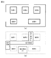
図3において、(a)は周辺環境の地図データを示し、(b)は地図データにおける移動ロボット1の走行領域1,2,3、及び指定(特定)領域A1を示している。(a)の周辺環境の地図データは、予め記憶されているものであり、(b)の走行領域1,2,3及び指定(特定)領域A1は、ユーザの所定の操作により、走行領域記憶手段16及び特定領域記憶手段17に記憶することができる。
3A shows map data of the surrounding environment, and FIG. 3B shows
図4は、移動ロボット1に構成されたレーザ距離センサ6から物体A,Bなどに対しレーザを照射して物体を判別している状態を示している。同図において矢印で表しているように、移動ロボット1のレーザ距離センサ6から照射されるレーザ光は、移動ロボット1の正面側を基準として、左右に90度の範囲、すなわち180度の範囲で照射される。そして、太い黒線で表しているように、反射光により物体A,Bや周辺環境の境界までの距離を測定することができる。図4に示されている検出状態は、レーザ距離センサ6の距離データと地図データ10をマッチング処理により照合して、移動ロボット1の位置と姿勢を同定(推定)した結果である。つまり、地図データ10と一致している距離データにより移動ロボット1の位置と姿勢が同定されたと見なすことができる。
FIG. 4 shows a state in which an object is discriminated by irradiating a laser to the objects A and B from the laser distance sensor 6 configured in the
図4の位置同定結果を分類すると、図5のようになる。距離データのうち、図5(a)(b)(c)(d)はそれぞれ太線で分類分けをしたことを示している。 4 is classified as shown in FIG. Of the distance data, FIGS. 5A, 5B, 5C, and 5D indicate that the classification is performed with bold lines.
図5において、(a)は図3(a)に示す地図データ10と再度比較することにより、地図データ10と一致した距離データであることを示している。これらのデータは地図に記載されたものであることから、固定物あるいは静止物と見なすことができる。
In FIG. 5, (a) indicates distance data that matches the
図5(b)は予め記憶された走行領域内に物体Aが置かれていると判定された状態を示している。走行領域2内に存在する物体Aは、移動ロボット1の走行の障害となり得る。つまり、これから走行する予定の走行領域上に物体Aがあるため、予定している走行経路で走行すると、衝突する可能性があると判断される。なお、物体Aの概略の大きさは距離データにより推定することはできるが、それ以上の特定をするものではない。
FIG. 5B shows a state in which it is determined that the object A is placed in the travel area stored in advance. The object A existing in the
ここにおいて、走行領域記憶手段12に走行領域2が記憶されている場合においては、図4で示すように、存在が判定された「物体」から、走行領域2内に存在する「物体」を抽出する。実施例においては、走行領域が3箇所設定されているが、走行領域内に存在する「物体」の判別は、移動ロボット1が当該走行領域内に侵入する際に行えばよい。つまり、走行領域1内に存在する「物体」の判別は、入り口からこのエリア内に入る際に行い、走行領域3内に存在する「物体」の判別は、走行領域2の終端から走行領域3に入るまでに行うことも可能である。また、走行中に、走行領域に侵入してくる場合には、それにも対応する必要がある。
Here, when the
図5(c)は予め記憶された指定領域A1内に台車Bが置かれていると判定された状態を示している。指定領域A1内の台車Bは、移動ロボット1の走行の障害とはならないが、この指定領域A1を台車置場として運用する場合には、検出されたものを台車Bと見なすことができる。これにより、台車置場である指定領域A1に台車があれば、移動ロボット1で台車を搬送することを要求していることを意味している。従って、検出した移動ロボット1が他の作業をしていない場合には、それを牽引して指定される搬送先まで台車Bを自動的に搬送することができる。また、移動ロボット1が他の仕事をしている場合、あるいは、他の場所に移動中である場合には、台車Bを発見したことを通信により外部にある上位制御装置に連絡することもできる。なお、物体の大きさにより、台車と異なるものが置かれた場合には、それを判断することも可能である。
FIG. 5C shows a state in which it is determined that the carriage B is placed in the designated area A1 stored in advance. The cart B in the designated area A1 does not become an obstacle to the traveling of the
図5(d)は走行領域1、2、3及び指定領域以外に物体が存在すると判定された状態を示している。「物体」の存在が判別されながら、走行領域内にも指定領域内にも存在しなく、地図物体でもない物体は、他の物として判断され、処理される。
FIG. 5D shows a state in which it is determined that an object exists in areas other than the
以上の構成によれば、照射するレーザ光の反射光により周囲環境に設けられた物体を識別し、周辺環境内で移動可能に配置された移動ロボット1の位置と角度を推定する位置同定装置7において、移動ロボット1が走行する周辺環境の地図データを記憶しており、移動ロボット1から前記周辺環境に設けられた物体までの距離を測定するレーザ距離センサ6と、該レーザ距離センサ6により測定された移動ロボット1から物体までの距離データと地図データとにより前記周辺環境に設けられた物体を判別する手段と、移動ロボット1の走行領域を記憶する走行領域記憶手段12と、移動ロボット1の走行領域とは別の特定領域を記憶する特定領域記憶手段13と、走行領域記憶手段12に記憶された移動ロボット1の走行領域内又は特定領域記憶手段13に記憶された特定領域内に物体が置かれているのか否かの判定をする物体判定手段14とを備えたものである。これにより、同定した位置と姿勢を基に、距離データと地図データ10を再度照合することで、簡単に、距離データを地図データ10と一致する物体、走行領域上にある物体、特定領域にある物体、その他の領域にある物体に分類することができる。従来、距離データのうち、接近していることを示す短い距離データを基に移動ロボットの制御を行っていたことに対して、その接近した距離データの種類を情報として提供できるので、移動ロボット1を減速・停止するべきかを判断できるため、より優れたロボットの制御を行うことができる。
According to the above configuration, the
また、本実施形態の位置同定手段においては、レーザ距離センサ6による移動ロボット1から物体までの距離の測定を複数回行い、該複数回の測定により得られた複数の距離データに基づき、物体が移動体であるのか静止体であるのかを分類することができる。さらに、制御装置は、移動ロボット1が物体に接近したことを距離データにより判断し、物体判定手段14により判定された物体が走行領域内に置かれているか否かの判定に基づき、走行経路を変更する。さらに、制御装置は、移動ロボット1が物体に接近したことを距離データにより判断しときに移動ロボット1を減速させ、該移動ロボット1が物体に衝突される前に停止する。なお、接近した物体が地図データ10と一致する場合には、その物体は静止物、あるいは、停止物と見なせるので、安全走行が保証できる範囲で、走行速度の減速する割合を少なくすることも可能である。
In the position identification unit of the present embodiment, the distance from the
1 移動ロボット
2 相対位置演算部
3 制御指令部
4 走行制御部
5 左右モータ
6 レーザ距離センサ(距離センサ)
7 位置同定手段(位置同定装置)
8 通信装置
9 目標点指令装置
10 地図データ
11 データ照合部
12 走行領域記憶手段
13 特定領域記憶手段(指定領域記憶手段)
14 物体判定手段
15 地図物体近接判断部
16 走行障害物体処理部
17 指定領域物体処理部
18 車両速度制限演算部
DESCRIPTION OF
7 Position identification means (position identification device)
DESCRIPTION OF SYMBOLS 8
DESCRIPTION OF
Claims (7)
前記移動体から前記周囲環境に設けられた物体までの距離を測定する距離センサと、
該距離センサにより測定された前記移動体から前記物体までの距離データと前記地図データとにより前記周囲環境に設けられた物体を判別する手段と、
前記移動体の走行領域を記憶する走行領域記憶手段と、
該走行領域記憶手段に記憶された前記移動体の走行領域内に前記物体が置かれているか否かを判定する物体判定手段と、
を備えたことを特徴とする位置同定装置。 In a position identification device that identifies an object provided in an ambient environment by reflected light of a laser beam to be irradiated, and estimates a position and an angle of the movable body arranged to be movable in the surrounding environment, the periphery in which the movable body travels It stores environmental map data,
A distance sensor for measuring a distance from the moving body to an object provided in the surrounding environment;
Means for discriminating an object provided in the surrounding environment from distance data from the moving body to the object measured by the distance sensor and the map data;
Traveling region storage means for storing the traveling region of the moving body;
Object judging means for judging whether or not the object is placed in the traveling area of the moving body stored in the traveling area storage means;
A position identification device comprising:
前記移動体から前記周囲環境に設けられた物体までの距離を測定する距離センサと、
該距離センサにより測定された前記移動体から前記物体までの距離データと前記地図データとにより前記周囲環境に設けられた物体を判別する手段と、
前記移動体の走行領域を記憶する走行領域記憶手段と、
前記移動体の走行領域とは別の特定領域を記憶する特定領域記憶手段と、
前記走行領域記憶手段に記憶された前記移動体の走行領域内又は前記特定領域記憶手段に記憶された前記特定領域内に前記物体が置かれているのか否かを判定する物体判定手段と、
を備えたことを特徴とする位置同定装置。 In a position identification device that identifies an object provided in an ambient environment by reflected light of a laser beam to be irradiated, and estimates a position and an angle of the movable body arranged to be movable in the surrounding environment, the periphery in which the movable body travels It stores environmental map data,
A distance sensor for measuring a distance from the moving body to an object provided in the surrounding environment;
Means for discriminating an object provided in the surrounding environment from distance data from the moving body to the object measured by the distance sensor and the map data;
Traveling region storage means for storing the traveling region of the moving body;
Specific area storage means for storing a specific area different from the traveling area of the moving body;
An object determination means for determining whether or not the object is placed in a traveling area of the moving body stored in the traveling area storage means or in the specific area stored in the specific area storage means;
A position identification device comprising:
前記地図データの特定領域を記憶する特定領域記憶手段と、
前記地図データと前記推定した位置と角度とを用いて、前記特定領域に物体が置かれているか否かを判定する物体判定手段と、
を備えたことを特徴とする位置同定装置。 In a position identification device that estimates a position and an angle of the moving body using a distance sensor that measures a distance to a surrounding object, map data of a surrounding environment where the moving body travels, and distance data measured by the distance sensor ,
Specific area storage means for storing the specific area of the map data;
Using the map data and the estimated position and angle, object determination means for determining whether an object is placed in the specific area;
A position identification device comprising:
前記制御装置は、前記移動ロボットが前記物体に接近したことを前記距離データにより判断し、前記物体判定手段により判定された前記物体が前記走行領域内に置かれているか否かの判定に基づき、走行経路を変更することを特徴とする移動ロボット。 A mobile robot comprising the position identification device according to any one of claims 1 to 3 and a control device that automatically controls autonomous traveling,
The control device determines, based on the distance data, that the mobile robot has approached the object, and based on the determination as to whether or not the object determined by the object determination means is placed in the travel area, A mobile robot characterized by changing a travel route.
The movement according to claim 4, further comprising a communication device for notifying the outside when the object determination means determines that the object is placed in the designated area. robot.
Priority Applications (4)
| Application Number | Priority Date | Filing Date | Title |
|---|---|---|---|
| JP2013072203A JP2014197294A (en) | 2013-03-29 | 2013-03-29 | Position identification device and mobile robot having the same |
| PCT/JP2014/055386 WO2014156502A1 (en) | 2013-03-29 | 2014-03-04 | Position identification device and mobile robot provided with same |
| US14/778,145 US9804605B2 (en) | 2013-03-29 | 2014-03-04 | Position identification device and mobile robot provided with same |
| CN201480019286.6A CN105074602B (en) | 2013-03-29 | 2014-03-04 | Position identification device and mobile robot with the position identification device |
Applications Claiming Priority (1)
| Application Number | Priority Date | Filing Date | Title |
|---|---|---|---|
| JP2013072203A JP2014197294A (en) | 2013-03-29 | 2013-03-29 | Position identification device and mobile robot having the same |
Related Child Applications (1)
| Application Number | Title | Priority Date | Filing Date |
|---|---|---|---|
| JP2017103168A Division JP6412207B2 (en) | 2017-05-25 | 2017-05-25 | Position identification device |
Publications (2)
| Publication Number | Publication Date |
|---|---|
| JP2014197294A true JP2014197294A (en) | 2014-10-16 |
| JP2014197294A5 JP2014197294A5 (en) | 2016-02-18 |
Family
ID=51623492
Family Applications (1)
| Application Number | Title | Priority Date | Filing Date |
|---|---|---|---|
| JP2013072203A Pending JP2014197294A (en) | 2013-03-29 | 2013-03-29 | Position identification device and mobile robot having the same |
Country Status (4)
| Country | Link |
|---|---|
| US (1) | US9804605B2 (en) |
| JP (1) | JP2014197294A (en) |
| CN (1) | CN105074602B (en) |
| WO (1) | WO2014156502A1 (en) |
Cited By (3)
| Publication number | Priority date | Publication date | Assignee | Title |
|---|---|---|---|---|
| CN104331078A (en) * | 2014-10-31 | 2015-02-04 | 东北大学 | Multi-robot cooperative localization method based on position mapping algorithm |
| JP2016206876A (en) * | 2015-04-21 | 2016-12-08 | Cyberdyne株式会社 | Travel route teaching system and method for autonomous mobile body |
| JP2017224048A (en) * | 2016-06-13 | 2017-12-21 | 村田機械株式会社 | Movement target determination device and movement target determination method |
Families Citing this family (25)
| Publication number | Priority date | Publication date | Assignee | Title |
|---|---|---|---|---|
| DE102015109775B3 (en) | 2015-06-18 | 2016-09-22 | RobArt GmbH | Optical triangulation sensor for distance measurement |
| DE102015114883A1 (en) | 2015-09-04 | 2017-03-09 | RobArt GmbH | Identification and localization of a base station of an autonomous mobile robot |
| DE102015119501A1 (en) | 2015-11-11 | 2017-05-11 | RobArt GmbH | Subdivision of maps for robot navigation |
| DE102015119865B4 (en) | 2015-11-17 | 2023-12-21 | RobArt GmbH | Robot-assisted processing of a surface using a robot |
| JP2017111790A (en) * | 2015-12-10 | 2017-06-22 | パナソニック インテレクチュアル プロパティ コーポレーション オブ アメリカPanasonic Intellectual Property Corporation of America | Movement control method, autonomous mobile robot, and program |
| DE102015121666B3 (en) | 2015-12-11 | 2017-05-24 | RobArt GmbH | Remote control of a mobile, autonomous robot |
| JP6830452B2 (en) * | 2016-02-05 | 2021-02-17 | 株式会社日立産機システム | Position detector and control device |
| DE102016102644A1 (en) | 2016-02-15 | 2017-08-17 | RobArt GmbH | Method for controlling an autonomous mobile robot |
| JP6711138B2 (en) * | 2016-05-25 | 2020-06-17 | 村田機械株式会社 | Self-position estimating device and self-position estimating method |
| CN106227204B (en) * | 2016-07-08 | 2020-03-10 | 百度在线网络技术(北京)有限公司 | Vehicle-mounted device and system, method and device for controlling unmanned vehicle |
| WO2018098659A1 (en) * | 2016-11-30 | 2018-06-07 | 深圳前海达闼云端智能科技有限公司 | Robot control method, device, server and robot |
| US11709489B2 (en) | 2017-03-02 | 2023-07-25 | RobArt GmbH | Method for controlling an autonomous, mobile robot |
| JP6767567B2 (en) * | 2017-03-28 | 2020-10-14 | 株式会社日立産機システム | Mapping system and robot system |
| CN106983454B (en) * | 2017-05-12 | 2020-11-20 | 北京小米移动软件有限公司 | Sweeping robot sweeping method and sweeping robot |
| JP2019086812A (en) * | 2017-11-01 | 2019-06-06 | 株式会社日立産機システム | Mobile body system |
| CN108521809A (en) * | 2017-12-18 | 2018-09-11 | 深圳市大疆创新科技有限公司 | Obstacle information reminding method, system, unit and recording medium |
| CN108344414A (en) * | 2017-12-29 | 2018-07-31 | 中兴通讯股份有限公司 | A kind of map structuring, air navigation aid and device, system |
| CN108303986B (en) * | 2018-03-09 | 2021-02-26 | 哈工大机器人(昆山)有限公司 | Temporary obstacle processing method for laser slam navigation |
| WO2019183727A1 (en) * | 2018-03-27 | 2019-10-03 | Avidbots Corp | Safety systems for semi-autonomous devices and methods of using the same |
| JP7176241B2 (en) * | 2018-06-15 | 2022-11-22 | トヨタ自動車株式会社 | Autonomous mobile body and control program for autonomous mobile body |
| EP3660617A4 (en) * | 2018-08-14 | 2021-04-14 | Chiba Institute of Technology | Mobile robot |
| US20220083067A1 (en) * | 2018-12-17 | 2022-03-17 | Chiba Institute Of Technology | Information processing apparatus and mobile robot |
| JP7107278B2 (en) * | 2019-05-13 | 2022-07-27 | トヨタ自動車株式会社 | Autonomous mobile device control system |
| JP7221839B2 (en) * | 2019-10-08 | 2023-02-14 | 国立大学法人静岡大学 | Autonomous Mobile Robot and Control Program for Autonomous Mobile Robot |
| CN111079607A (en) * | 2019-12-05 | 2020-04-28 | 灵动科技(北京)有限公司 | Automatic driving system with tracking function |
Citations (6)
| Publication number | Priority date | Publication date | Assignee | Title |
|---|---|---|---|---|
| JPH05205198A (en) * | 1992-01-29 | 1993-08-13 | Mazda Motor Corp | Obstacle detection device for vehicle |
| JP2004280451A (en) * | 2003-03-14 | 2004-10-07 | Matsushita Electric Works Ltd | Autonomous moving device |
| JP2007200070A (en) * | 2006-01-27 | 2007-08-09 | Secom Co Ltd | Mobile robot |
| JP2008200770A (en) * | 2007-02-16 | 2008-09-04 | Toshiba Corp | Robot, and control method thereof |
| JP2012150828A (en) * | 2007-02-22 | 2012-08-09 | Fujitsu Ltd | Patrol robot and autonomous travel method of patrol robot |
| JP2012256344A (en) * | 2012-08-06 | 2012-12-27 | Hitachi Industrial Equipment Systems Co Ltd | Robot system |
Family Cites Families (4)
| Publication number | Priority date | Publication date | Assignee | Title |
|---|---|---|---|---|
| US5461357A (en) | 1992-01-29 | 1995-10-24 | Mazda Motor Corporation | Obstacle detection device for vehicle |
| DE19950033B4 (en) * | 1999-10-16 | 2005-03-03 | Bayerische Motoren Werke Ag | Camera device for vehicles |
| DE10231362A1 (en) * | 2002-07-11 | 2004-01-22 | Robert Bosch Gmbh | Device for monitoring the environment in a vehicle |
| JP2009109200A (en) | 2007-10-26 | 2009-05-21 | Hitachi Ltd | Position attitude estimation system, position attitude estimation device, and position attitude estimation method |
-
2013
- 2013-03-29 JP JP2013072203A patent/JP2014197294A/en active Pending
-
2014
- 2014-03-04 US US14/778,145 patent/US9804605B2/en active Active
- 2014-03-04 WO PCT/JP2014/055386 patent/WO2014156502A1/en active Application Filing
- 2014-03-04 CN CN201480019286.6A patent/CN105074602B/en not_active Expired - Fee Related
Patent Citations (6)
| Publication number | Priority date | Publication date | Assignee | Title |
|---|---|---|---|---|
| JPH05205198A (en) * | 1992-01-29 | 1993-08-13 | Mazda Motor Corp | Obstacle detection device for vehicle |
| JP2004280451A (en) * | 2003-03-14 | 2004-10-07 | Matsushita Electric Works Ltd | Autonomous moving device |
| JP2007200070A (en) * | 2006-01-27 | 2007-08-09 | Secom Co Ltd | Mobile robot |
| JP2008200770A (en) * | 2007-02-16 | 2008-09-04 | Toshiba Corp | Robot, and control method thereof |
| JP2012150828A (en) * | 2007-02-22 | 2012-08-09 | Fujitsu Ltd | Patrol robot and autonomous travel method of patrol robot |
| JP2012256344A (en) * | 2012-08-06 | 2012-12-27 | Hitachi Industrial Equipment Systems Co Ltd | Robot system |
Cited By (3)
| Publication number | Priority date | Publication date | Assignee | Title |
|---|---|---|---|---|
| CN104331078A (en) * | 2014-10-31 | 2015-02-04 | 东北大学 | Multi-robot cooperative localization method based on position mapping algorithm |
| JP2016206876A (en) * | 2015-04-21 | 2016-12-08 | Cyberdyne株式会社 | Travel route teaching system and method for autonomous mobile body |
| JP2017224048A (en) * | 2016-06-13 | 2017-12-21 | 村田機械株式会社 | Movement target determination device and movement target determination method |
Also Published As
| Publication number | Publication date |
|---|---|
| US20160282873A1 (en) | 2016-09-29 |
| CN105074602B (en) | 2018-10-26 |
| US9804605B2 (en) | 2017-10-31 |
| WO2014156502A1 (en) | 2014-10-02 |
| CN105074602A (en) | 2015-11-18 |
Similar Documents
| Publication | Publication Date | Title |
|---|---|---|
| WO2014156502A1 (en) | Position identification device and mobile robot provided with same | |
| CN107710304B (en) | Route prediction device | |
| CN102782600B (en) | Autonomous moving object and control method | |
| CN104554272A (en) | Path planning for evasive steering maneuver in presence of target vehicle and surrounding objects | |
| WO2015072002A1 (en) | Mobile robot system | |
| JP6654923B2 (en) | Map information output device | |
| CN104554258A (en) | Path planning for evasive steering manuever employing virtual potential field technique | |
| CN111095384A (en) | Information processing device, autonomous moving device, method, and program | |
| CN114523963B (en) | System and method for predicting road collisions with host vehicles | |
| CN115147587A (en) | Obstacle detection method and device and electronic equipment | |
| JP4457830B2 (en) | Autonomous mobile device | |
| JP6412207B2 (en) | Position identification device | |
| JP2012168990A (en) | Autonomous mobile device | |
| CN112327848A (en) | Robot obstacle avoidance method and device, storage medium and electronic equipment | |
| JP2021144435A (en) | Collision prevention device, mobile body, and program | |
| WO2016009585A1 (en) | Autonomous mobile object and method of controlling same | |
| KR20200084938A (en) | Method and Apparatus for Planning Car Motion | |
| KR102324989B1 (en) | Mobile body, management server, and operating method thereof | |
| US20220397904A1 (en) | Information processing apparatus, information processing method, and program | |
| JP6594565B1 (en) | In-vehicle device, information processing method, and information processing program | |
| JP2015056123A (en) | Environmental map generation control device of moving body, moving body, and environmental map generation method of moving body | |
| Halldén et al. | Obstacle circumvention by automated guided vehicles in industrial environments | |
| JP2014182591A (en) | Movable body environment map generation controller, movable body and movable body environment map generation method | |
| JP6687313B1 (en) | Transport system | |
| JP2013237125A (en) | Method for controlling movement of movable body |
Legal Events
| Date | Code | Title | Description |
|---|---|---|---|
| A521 | Request for written amendment filed |
Free format text: JAPANESE INTERMEDIATE CODE: A523 Effective date: 20151224 |
|
| A621 | Written request for application examination |
Free format text: JAPANESE INTERMEDIATE CODE: A621 Effective date: 20151224 |
|
| A131 | Notification of reasons for refusal |
Free format text: JAPANESE INTERMEDIATE CODE: A131 Effective date: 20160802 |
|
| A521 | Request for written amendment filed |
Free format text: JAPANESE INTERMEDIATE CODE: A523 Effective date: 20160928 |
|
| A02 | Decision of refusal |
Free format text: JAPANESE INTERMEDIATE CODE: A02 Effective date: 20170228 |