JP2014194884A - Crimp terminal - Google Patents
Crimp terminal Download PDFInfo
- Publication number
- JP2014194884A JP2014194884A JP2013070890A JP2013070890A JP2014194884A JP 2014194884 A JP2014194884 A JP 2014194884A JP 2013070890 A JP2013070890 A JP 2013070890A JP 2013070890 A JP2013070890 A JP 2013070890A JP 2014194884 A JP2014194884 A JP 2014194884A
- Authority
- JP
- Japan
- Prior art keywords
- terminal
- crimping
- crimp
- crimp terminal
- guide portion
- Prior art date
- Legal status (The legal status is an assumption and is not a legal conclusion. Google has not performed a legal analysis and makes no representation as to the accuracy of the status listed.)
- Granted
Links
- 238000002788 crimping Methods 0.000 claims abstract description 83
- 239000004020 conductor Substances 0.000 claims description 53
- 238000000576 coating method Methods 0.000 claims description 6
- 239000011248 coating agent Substances 0.000 claims description 4
- 230000000087 stabilizing effect Effects 0.000 abstract description 2
- 230000002708 enhancing effect Effects 0.000 abstract 1
- 230000000694 effects Effects 0.000 description 16
- 239000012212 insulator Substances 0.000 description 7
- 238000000034 method Methods 0.000 description 7
- 238000003780 insertion Methods 0.000 description 6
- 230000037431 insertion Effects 0.000 description 6
- 229910052751 metal Inorganic materials 0.000 description 3
- 239000002184 metal Substances 0.000 description 3
- 239000011347 resin Substances 0.000 description 3
- 229920005989 resin Polymers 0.000 description 3
- 229910052782 aluminium Inorganic materials 0.000 description 2
- XAGFODPZIPBFFR-UHFFFAOYSA-N aluminium Chemical compound [Al] XAGFODPZIPBFFR-UHFFFAOYSA-N 0.000 description 2
- 238000009413 insulation Methods 0.000 description 2
- 239000000463 material Substances 0.000 description 2
- 230000000007 visual effect Effects 0.000 description 2
- 229910000838 Al alloy Inorganic materials 0.000 description 1
- RYGMFSIKBFXOCR-UHFFFAOYSA-N Copper Chemical compound [Cu] RYGMFSIKBFXOCR-UHFFFAOYSA-N 0.000 description 1
- 229910000881 Cu alloy Inorganic materials 0.000 description 1
- 229910052802 copper Inorganic materials 0.000 description 1
- 239000010949 copper Substances 0.000 description 1
- 238000010586 diagram Methods 0.000 description 1
- 238000001125 extrusion Methods 0.000 description 1
- 239000000126 substance Substances 0.000 description 1
- 239000000758 substrate Substances 0.000 description 1
- 238000004804 winding Methods 0.000 description 1
Images


Landscapes
- Connections Effected By Soldering, Adhesion, Or Permanent Deformation (AREA)
Abstract
Description
本発明は、圧着端子に関し、詳しくは、太物電線の中間ジョイントに用いることが好適な圧着端子に関する。 The present invention relates to a crimp terminal, and more particularly to a crimp terminal suitable for use in an intermediate joint of a thick wire.
幹線となる電線の中間の被覆を所定長さで皮剥し、露出した導体に対して枝線となる電線の導体を接続するために、圧着端子が用いられる(下記特許文献1、2参照)。以下、簡単に説明をする。
A crimping terminal is used to peel off the intermediate coating of the electric wire to be a trunk line with a predetermined length and connect the conductor of the electric wire to be a branch line to the exposed conductor (see
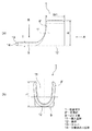
図6(a)において、引用符号51は幹線となる電線、引用符号52は枝線となる電線をそれぞれ示す。電線51は、この中間に導体露出部53が形成される。導体露出部53は、被覆54の中間を所定長さで皮剥して導体55を露出させることにより形成される。一方、電線52は、この端末に導体露出部56が形成される。導体露出部56は、被覆57の端末を所定長さで皮剥して導体58を露出させることにより形成される。
In FIG. 6A,
引用符号59は導体露出部53、56同士を接続するための圧着端子を示す。導体露出部53、56は、これらが重なった状態で圧着端子59の全体に加締めが施されると、圧着端子59により圧着されて電気的に接続される。圧着接続後は、テープ巻き60等で絶縁処理が施される。
図6(b)において、引用符号61は幹線となる電線、引用符号62は枝線となる電線をそれぞれ示す。また、引用符号63は圧着端子を示す。図6(b)は図6(a)と基本的に同じ構成であって、引用符号64は電線61の導体露出部を示す。また、引用符号65、66は電線61を構成する被覆、導体を示す。引用符号67は電線62の導体露出部を示す。また、引用符号68、69は電線62を構成する被覆、導体を示す。
In FIG. 6B,
導体露出部64、67は、これらが重なった状態で圧着端子63の全体に加締めが施されると、圧着端子63により圧着されて電気的に接続される。圧着接続状態における引用符号70はベルマウスを示す。また、引用符号71は視認部を示す。視認部71は、外部から導体露出部64、67の圧着接続状態を確認する切り欠き窓のような形状部分に形成される。
The conductor exposed
ところで、上記従来の圧着端子59、63にあっては、この全体に加締めが施されることから、言い換えれば端子全体が圧着部分として形成されることから、端子圧着装置による圧着端子59、63への加締め時において端子位置が安定しないという問題点を有する。端子位置が安定しなければ、圧着接続状態に対する信頼性の低下を招いてしまうという問題点も有する。
By the way, since the
本発明は、上記した事情に鑑みてなされたもので、加締め時における端子位置を安定させることが可能であり、また、圧着接続状態に対する信頼性を高めることも可能な圧着端子を提供することを課題とする。 The present invention has been made in view of the above circumstances, and provides a crimp terminal capable of stabilizing the terminal position during caulking and also improving the reliability with respect to the crimp connection state. Is an issue.
上記課題を解決するためになされた請求項1に記載の本発明は、被覆を除去して導体を露出させた導体露出部を複数重ねた上でこれらを圧着接続状態にする圧着部を有する圧着端子において、前記圧着部の基部に連続するガイド部を有し、該ガイド部を、端子圧着装置による前記圧着部への加締め時に用いる端子固定部分として形成することを特徴とする。
The present invention according to
請求項2に記載の本発明は、請求項1に記載の圧着端子において、前記ガイド部を、前記端子圧着装置の端子固定部に形成された凹部に対し挿抜自在となる凸片形状の部分、且つ前記凹部への挿入時には該凹部にて固定される凸片形状の部分に形成することを特徴とする。
The invention according to
請求項3に記載の本発明は、請求項2に記載の圧着端子において、前記ガイド部の先端を、前記凹部の奥部分に突き当てて位置決めをする部分として形成することを特徴とする。 According to a third aspect of the present invention, in the crimp terminal according to the second aspect, the tip of the guide portion is formed as a portion to be positioned by abutting against a back portion of the concave portion.
請求項4に記載の本発明は、請求項1、2又は3に記載の圧着端子において、当該圧着端子を太物電線の中間ジョイントに用いることを特徴とする。 According to a fourth aspect of the present invention, in the crimp terminal according to the first, second, or third aspect, the crimp terminal is used for an intermediate joint of a thick wire.
請求項1に記載された本発明によれば、端子固定部分としてのガイド部を有することから、このようなガイド部を用いることで端子圧着装置に対し圧着端子を固定することができる。従って、本発明によれば、圧着部への加締め時において端子位置を安定させることができるという効果を奏する。また、端子位置を安定させることができることから、圧着接続状態に対する信頼性を高めることができるという効果も奏する。 According to the first aspect of the present invention, since the guide portion as the terminal fixing portion is provided, the crimp terminal can be fixed to the terminal crimping device by using such a guide portion. Therefore, according to the present invention, it is possible to stabilize the terminal position at the time of crimping to the crimping portion. Moreover, since the terminal position can be stabilized, there is also an effect that the reliability with respect to the crimping connection state can be enhanced.
請求項2に記載された本発明によれば、請求項1の効果に加え次のような効果も奏する。すなわち、ガイド部の形状を凸片形状に形成することから、端子圧着装置の凹部に対し挿抜し易く、また、固定し易いガイド部にすることができるという効果を奏する。これにより、作業性のよい圧着端子を提供することができるという効果も奏する。 According to the second aspect of the present invention, in addition to the effect of the first aspect, the following effect is also achieved. That is, since the shape of the guide portion is formed in a convex piece shape, the guide portion can be easily inserted into and removed from the concave portion of the terminal crimping apparatus and can be easily fixed. Thereby, there also exists an effect that a crimp terminal with good workability can be provided.
請求項3に記載された本発明によれば、請求項2の効果に加え次のような効果も奏する。すなわち、ガイド部の先端を端子圧着装置の凹部の奥部分に突き当てるようにすることから、突き当てにより位置決めをすることができるという効果を奏する。これにより、圧着接続状態に対する信頼性を更に高めることができるという効果も奏する。
According to the present invention described in claim 3, in addition to the effect of
請求項4に記載された本発明によれば、請求項1、2又は3の効果に加え次のような効果も奏する。すなわち、本発明の圧着端子を太物電線の中間ジョイント用として提供することができるという効果を奏する。
According to the present invention described in
圧着部とガイド部とを有する圧着端子を提供する。ガイド部は、圧着部への加締め時において用いられる端子固定部分として形成される。 A crimp terminal having a crimp portion and a guide portion is provided. The guide part is formed as a terminal fixing part used when crimping the crimping part.
以下、図面を参照しながら実施例を説明する。図1は本発明の圧着端子とこの圧着端子によりジョイントされる電線の側面図である。また、図2(a)は圧着端子の側面図、図2(b)は図2(a)のA視の図である。また、図3(a)は図2(a)のB視の図、図3(b)は圧着端子の斜視図である。また、図4及び図5は端子圧着装置及び圧着接続に係る説明図である。 Hereinafter, embodiments will be described with reference to the drawings. FIG. 1 is a side view of a crimp terminal of the present invention and an electric wire jointed by the crimp terminal. Moreover, Fig.2 (a) is a side view of a crimp terminal, FIG.2 (b) is a figure of A view of Fig.2 (a). 3A is a view as seen from B in FIG. 2A, and FIG. 3B is a perspective view of the crimp terminal. 4 and 5 are explanatory diagrams relating to the terminal crimping apparatus and the crimping connection.
図1において、本発明の圧着端子1は、幹線となる電線2の中間に枝線となる電線3の端末をジョイントするために用いられる。先ず、電線2、3について説明をし、次に本発明の圧着端子1について説明をする。
In FIG. 1, the
電線2、3は、特に限定するものでないが、高圧の太物電線(高圧電線)であって、共に同じ構成のものが用いられる(高圧に限らず低圧の電線であってもよいものとする。また、異なるサイズであってもよいものとする)。このような電線2、3は、導体4と絶縁体5(被覆)とを備えて構成される。
The
導体4は、金属製であって導電性を有する。導体4は、断面円形状であって、電線2、3の一端から他端にかけてほぼ同じ径でのびるように形成される。導体4は、銅や銅合金、或いはアルミニウムやアルミニウム合金により製造される。導体4に関しては、素線を撚り合わせてなる導体構造のものや、断面矩形又は丸形(円形)となる棒状の導体構造(例えば平角単心や丸単心となる導体構造であり、この場合、電線自体も棒状となる)のもののいずれであってもよいものとする。本実施例においては、アルミニウム製の撚り線が採用される。
The
絶縁体5は、樹脂製であって絶縁性を有する。絶縁体5は、導体4の外面に所定の肉厚で押出成形により断面円形状に形成される。尚、絶縁性の樹脂材料としては、PPやPVC、架橋PE等が挙げられるものとする。樹脂材料に関しては、耐摩耗性や耐薬品性、耐熱性等に配慮して適宜選定されるものとする。
The
幹線となる電線2は、この中間に導体露出部6が形成される。導体露出部6は、絶縁体5の中間を所定長さで皮剥して導体4を露出させることにより形成される。一方、枝線となる電線3は、この端末に導体露出部7が形成される。導体露出部7は、絶縁体5の端末を所定長さで皮剥して導体4を露出させることにより形成される。導体露出部7は、本実施例において、電線2の導体露出部6と同じくらいの長さに形成される。
A conductor exposed
電線2、3は、これらの導体露出部6、7を重ねた上で圧着端子1により圧着接続される。
The
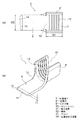
図1ないし図3において、圧着端子1は、金属製であって導電性を有する。圧着端子1は、所定の厚みとなる金属板をプレス加工することにより形成される。尚、圧着端子1は、上記の如く、幹線となる電線2の中間(導体露出部6)に枝線となる電線3の端末(導体露出部7)をジョイントするため端子金具であることから、名称を中間ジョイント端子と読み替えてもよいものとする。
1 to 3, the
圧着端子1は、圧着部8と、ガイド部9とを有する。圧着部8とガイド部9は、一体に形成される。尚、ダッシュ付きの圧着部8′は、加締めを施す前の状態を示すものとする。また、ダッシュ無しの圧着部8は、加締め後の状態を示すものとする。
The
図2及び図3において、圧着部8′は、所謂一対のワイヤーバレルであって、断面が略U字状となる形状に形成される。このような形状の圧着部8′の内面には、複数のセレーション10が形成される。本実施例のセレーション10は、プレス加工により線打ちされた溝形状に形成される(図中の本数は一例であるものとする)。尚、溝形状以外としては、例えばディンプル形状等が挙げられるものとする。
2 and 3, the crimping
圧着部8′の内面により区画される内部空間は、導体露出部6、7に対する挿入空間11として形成される。圧着部8′は、このような挿入空間11が形成されるとともに、端子軸の方向と、圧着部8′の基部12の配置反対側方向とが開放されるように形成される。上記基部12は、底板又は基板となる部分であるものとする。
An internal space defined by the inner surface of the crimping
圧着部8′における端子軸の方向の幅W1と、基部12からの高さHは、導体露出部6、7のサイズ等に応じて適宜設定されるものとする。本実施例においては、加締めを施した時の形状がM字状になるような高さHに設定されるものとする。また、導体露出部6、7を包み込むことができるような高さHに設定されるものとする。
The width W1 in the direction of the terminal axis and the height H from the base 12 in the crimping
ガイド部9は、後述する端子圧着装置21(図4参照)による圧着部8′への加締め時に用いられる端子固定部分であって、基部12に連続するように形成される。このようなガイド部9は、端子軸の方向にのびる凸片形状の部分として形成される。また、ガイド部9は、端子圧着装置21の後述する端子固定部24に形成された凹部25に対し挿抜自在となる凸片形状の部分としても形成される。
The
ガイド部9は、端子軸の直交方向となる幅W2が一定(一例であるものとする)となるように形成される。また、ガイド部9は、先端を除く部分の肉厚Tが均一となるようにも形成される。
The
ガイド部9の先端部分には、テーパ13と、位置決め当接面14とが形成される。テーパ13は、後述する凹部25に対し引っ掛かり難くする部分として形成される(エッジ処理を施すのであれば、テーパ13でなくてもよいものとする)。位置決め当接面14は、ガイド部9の先端面であって、凹部25の奥部分に突き当てて位置決めをする部分として形成される。
A
本実施例のガイド部9は、図示形状からも分かるが、公知のバスバーのタブに似た形状に形成される。
As can be seen from the illustrated shape, the
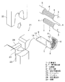
続いて、図4を参照しながら端子圧着装置21について説明をする。端子圧着装置21は、圧着端子1に加締めを施して圧着接続状態にするための装置として用いられる。
Next, the
図4において、端子圧着装置21は、加締め型上部(上型)としてのクリンパー22と、加締め型下部(下型)としてのアンビル23と、端子固定部24とを含んで構成される(ここで説明しない他の構成については公知のものと同じであるものとする)。
In FIG. 4, the
クリンパー22は、本実施例において、圧着端子1の圧着部8′を加締めによりM字状に変形させることができる形状に形成される。一方、アンビル23は、加締めの際に受け部分として機能することができる形状に形成される。また、アンビル23は、圧着端子1を置くことができる形状にも形成される。
In this embodiment, the
端子固定部24は、凹部25を有する。この凹部25は、圧着端子1のガイド部9を挿抜自在に固定する部分として、また、ガイド部9をガタ付きなく(ぐら付きなく)固定する部分として形成される。さらに、凹部25は、ガイド部9の形状(凸片形状)に合わせた凹み部分として形成される。このような凹部25の奥部分には、ガイド部9の位置決め当接面14に対する突き当て面26(図5参照)が形成される。
The
続いて、図4及び図5を参照しながら圧着端子1を用いての電線2、3のジョイント方法について、三つの工程を挙げながら説明をする。
Subsequently, the joint method of the
第一工程では、圧着端子1が端子圧着装置21にセットされる。圧着端子1は、このガイド部9が凹部25に挿入されると、ガタ付きなく(ぐら付きなく)固定される。圧着端子1は、端子圧着装置21へのセットの際に、位置決め当接面14が突き当て面26に突き当たるようにセットされると、圧着部8′がクリンパー22とアンビル23との位置に合うように配置される。すなわち、加締めを施すにあたり最適な位置に配置される(ここでの位置決めは一例であるものとする。本実施例の場合、寸法整合等で成立させることができることから、構造の簡素化や小型化に有効であるという利点を有する)。
In the first step, the
第二工程では、導体露出部6、7が圧着部8′の挿入空間11に挿入される。導体露出部6、7の挿入が完了すると、圧着部8′への加締めが可能な状態になる。尚、本実施例においては、導体露出部7の方が先に挿入される。
In the second step, the conductor exposed
第三工程では、導体露出部6、7が圧着端子1により圧着接続される。圧着部8′は、クリンパー22とアンビル23にて挟み込まれ、このような加締めにより図1に示す如くの圧着部8の状態に変形する。図示状態に圧着部8が変形すると、導体露出部6、7は圧着端子1により圧着接続された状態になる(圧着部8における引用符号27はベルマウスを示す)。
In the third step, the conductor exposed
圧着接続後、凹部25からガイド部9を抜くように圧着端子1が端子圧着装置21から取り外されると、一連の工程が完了する。
After the crimping connection, when the
尚、端子圧着装置21から取り外された後は、絶縁体5に跨るように圧着部8及び導体露出部6、7をテープ巻きする絶縁処理が施されるものとする(図示省略)。
In addition, after removing from the terminal crimping | compression-
以上、図1ないし図5を参照しながら説明してきたように、本発明の圧着端子1によれば、端子固定部分としてのガイド部9を有することから、このようなガイド部9を用いることにより圧着端子1を端子圧着装置21に対し固定することができる。従って、本発明の圧着端子1によれば、圧着部8′への加締め時において端子位置を安定させることができるという効果を奏する。
As described above with reference to FIGS. 1 to 5, according to the
また、本発明の圧着端子1によれば、上記の如く端子位置を安定させることができることから、圧着上の品質を確保し、以て圧着接続状態に対する信頼性を高めることができるという効果も奏する。
Further, according to the
さらに、本発明の圧着端子1によれば、ガイド部9の先端の位置決め当接面14を端子圧着装置21の凹部25の突き当て面26に突き当てることから、この突き当てにより圧着端子1の位置決めをし、確実に圧着接続をすることができるという効果も奏する。すなわち、圧着接続状態に対する信頼性を更に高めることができるという効果も奏する。
Furthermore, according to the crimping
本発明は本発明の主旨を変えない範囲で種々変更実施可能なことは勿論である。一例を挙げるとすると、中間ジョイントではなく電線2、3の端末同士を圧着接続する場合に、本発明の圧着端子1を用いることが挙げられる。
It goes without saying that the present invention can be variously modified without departing from the spirit of the present invention. If an example is given, when the terminal of the
尚、上記で説明した電線2、3のジョイント方法について特徴づけると、次のようになる。すなわち、電線2、3のジョイント方法は、「圧着端子1に形成されたガイド部9を端子圧着装置21の端子固定部24に固定する第一工程と、圧着端子1に形成された圧着部8′に複数の導体露出部6、7を挿入する第二工程と、圧着部8′に加締めを施して圧着部8の状態に変形させこれにより導体露出部6、7を圧着接続する第三工程と、を含む」ことを特徴とすることができる(ジョイント方法の効果は、圧着端子1の効果と同様である)。
In addition, it will become as follows if it characterizes about the joint method of the
1…圧着端子
2、3…電線
4…導体
5…絶縁体(被覆)
6、7…導体露出部
8、8′…圧着部
9…ガイド部
10…セレーション
11…挿入空間
12…基部
13…テーパ
14…位置決め当接面
21…端子圧着装置
22…クリンパー
23…アンビル
24…端子固定部
25…凹部
26…突き当て面
27…ベルマウス
DESCRIPTION OF
6, 7 ... Conductor exposed
Claims (4)
前記圧着部の基部に連続するガイド部を有し、該ガイド部を、端子圧着装置による前記圧着部への加締め時に用いる端子固定部分として形成する
ことを特徴とする圧着端子。 In a crimp terminal having a crimping part for making a crimped connection state after a plurality of conductor exposed parts in which the conductor is exposed by removing the coating,
A crimp terminal having a guide portion continuous with a base portion of the crimp portion, and forming the guide portion as a terminal fixing portion used when crimping the crimp portion with a terminal crimp device.
前記ガイド部を、前記端子圧着装置の端子固定部に形成された凹部に対し挿抜自在となる凸片形状の部分、且つ前記凹部への挿入時には該凹部にて固定される凸片形状の部分に形成する
ことを特徴とする圧着端子。 The crimp terminal according to claim 1,
The guide portion is a convex piece-shaped portion that can be inserted into and removed from the concave portion formed in the terminal fixing portion of the terminal crimping apparatus, and a convex piece-shaped portion that is fixed by the concave portion when inserted into the concave portion. A crimp terminal characterized by being formed.
前記ガイド部の先端を、前記凹部の奥部分に突き当てて位置決めをする部分として形成する
ことを特徴とする圧着端子。 The crimp terminal according to claim 2,
A crimp terminal, wherein the tip of the guide portion is formed as a portion to be positioned by abutting against a back portion of the recess.
当該圧着端子を太物電線の中間ジョイントに用いる
ことを特徴とする圧着端子。 In the crimp terminal according to claim 1, 2, or 3,
A crimp terminal characterized in that the crimp terminal is used for an intermediate joint of a thick wire.
Priority Applications (1)
| Application Number | Priority Date | Filing Date | Title |
|---|---|---|---|
| JP2013070890A JP6056062B2 (en) | 2013-03-29 | 2013-03-29 | Crimp terminal |
Applications Claiming Priority (1)
| Application Number | Priority Date | Filing Date | Title |
|---|---|---|---|
| JP2013070890A JP6056062B2 (en) | 2013-03-29 | 2013-03-29 | Crimp terminal |
Publications (2)
| Publication Number | Publication Date |
|---|---|
| JP2014194884A true JP2014194884A (en) | 2014-10-09 |
| JP6056062B2 JP6056062B2 (en) | 2017-01-11 |
Family
ID=51839985
Family Applications (1)
| Application Number | Title | Priority Date | Filing Date |
|---|---|---|---|
| JP2013070890A Active JP6056062B2 (en) | 2013-03-29 | 2013-03-29 | Crimp terminal |
Country Status (1)
| Country | Link |
|---|---|
| JP (1) | JP6056062B2 (en) |
Citations (4)
| Publication number | Priority date | Publication date | Assignee | Title |
|---|---|---|---|---|
| JPS5599087U (en) * | 1978-12-28 | 1980-07-10 | ||
| JPS63164182A (en) * | 1986-12-25 | 1988-07-07 | ヒロセ電機株式会社 | Wiring device |
| JPH0719992U (en) * | 1993-09-21 | 1995-04-07 | 菱星電装株式会社 | Core wire crimping device at joint part |
| JPH09330748A (en) * | 1996-06-07 | 1997-12-22 | Yazaki Corp | Wire crimping structure and wire crimping method |
-
2013
- 2013-03-29 JP JP2013070890A patent/JP6056062B2/en active Active
Patent Citations (4)
| Publication number | Priority date | Publication date | Assignee | Title |
|---|---|---|---|---|
| JPS5599087U (en) * | 1978-12-28 | 1980-07-10 | ||
| JPS63164182A (en) * | 1986-12-25 | 1988-07-07 | ヒロセ電機株式会社 | Wiring device |
| JPH0719992U (en) * | 1993-09-21 | 1995-04-07 | 菱星電装株式会社 | Core wire crimping device at joint part |
| JPH09330748A (en) * | 1996-06-07 | 1997-12-22 | Yazaki Corp | Wire crimping structure and wire crimping method |
Also Published As
| Publication number | Publication date |
|---|---|
| JP6056062B2 (en) | 2017-01-11 |
Similar Documents
| Publication | Publication Date | Title |
|---|---|---|
| EP2151893A1 (en) | A terminal fitting and a crimping method | |
| US8834213B2 (en) | Connection structure of crimping terminal to electric wire | |
| US8876564B2 (en) | Connection structure of crimping terminal to electric wire | |
| JP6422240B2 (en) | Connection structure, wire harness, and connector | |
| US8944862B2 (en) | Structure of connection of crimping terminal to electric wire | |
| JP6060015B2 (en) | Crimp structure for the wire of the crimp terminal | |
| US9147944B2 (en) | Terminal fitting | |
| JP2009009736A (en) | Terminal connection structure to aluminum wire | |
| JP2014187039A5 (en) | ||
| US20090221175A1 (en) | Wire Harness Interconnection and Retention Method and Apparatus | |
| US20140033520A1 (en) | Crimping jig | |
| JP5434095B2 (en) | Electric wire connection sleeve, repair electric wire, electric wire connection sleeve manufacturing method, and electric wire connection method | |
| JP6904147B2 (en) | Wire with terminal | |
| JP2010073320A (en) | Crimping structure of crimp terminal | |
| WO2015076177A1 (en) | Electric wire with terminals and manufacturing method for electric wire with terminals | |
| JP6786312B2 (en) | Crimping terminal | |
| WO2017115710A1 (en) | Method for producing cable with terminal, and cable with terminal | |
| JP5608496B2 (en) | Fiber conductor wire connection structure and connection method | |
| JP6056062B2 (en) | Crimp terminal | |
| JP6056063B2 (en) | Crimp terminal | |
| JP2021061208A (en) | Electric wire connection structure | |
| JP2011243519A (en) | Crimp terminal and flat cable with crimp terminal | |
| JP2010073345A (en) | Connection structure of terminal metal fitting, electric wire with terminal metal fitting, and manufacturing method of electric wire with terminal metal fitting | |
| JP2011124135A (en) | Flat cable with terminal fitting, and terminal crimping die for flat cable | |
| JP6784453B2 (en) | Manufacturing method of terminal crimping wire |
Legal Events
| Date | Code | Title | Description |
|---|---|---|---|
| A621 | Written request for application examination |
Free format text: JAPANESE INTERMEDIATE CODE: A621 Effective date: 20160218 |
|
| A977 | Report on retrieval |
Free format text: JAPANESE INTERMEDIATE CODE: A971007 Effective date: 20161027 |
|
| TRDD | Decision of grant or rejection written | ||
| A01 | Written decision to grant a patent or to grant a registration (utility model) |
Free format text: JAPANESE INTERMEDIATE CODE: A01 Effective date: 20161108 |
|
| A61 | First payment of annual fees (during grant procedure) |
Free format text: JAPANESE INTERMEDIATE CODE: A61 Effective date: 20161115 |
|
| R150 | Certificate of patent or registration of utility model |
Ref document number: 6056062 Country of ref document: JP Free format text: JAPANESE INTERMEDIATE CODE: R150 |
|
| R250 | Receipt of annual fees |
Free format text: JAPANESE INTERMEDIATE CODE: R250 |
|
| R250 | Receipt of annual fees |
Free format text: JAPANESE INTERMEDIATE CODE: R250 |
|
| R250 | Receipt of annual fees |
Free format text: JAPANESE INTERMEDIATE CODE: R250 |
|
| R250 | Receipt of annual fees |
Free format text: JAPANESE INTERMEDIATE CODE: R250 |
|
| S531 | Written request for registration of change of domicile |
Free format text: JAPANESE INTERMEDIATE CODE: R313531 |
|
| R350 | Written notification of registration of transfer |
Free format text: JAPANESE INTERMEDIATE CODE: R350 |
|
| R250 | Receipt of annual fees |
Free format text: JAPANESE INTERMEDIATE CODE: R250 |