JP2014190011A - Connection structure for door frame - Google Patents
Connection structure for door frame Download PDFInfo
- Publication number
- JP2014190011A JP2014190011A JP2013065302A JP2013065302A JP2014190011A JP 2014190011 A JP2014190011 A JP 2014190011A JP 2013065302 A JP2013065302 A JP 2013065302A JP 2013065302 A JP2013065302 A JP 2013065302A JP 2014190011 A JP2014190011 A JP 2014190011A
- Authority
- JP
- Japan
- Prior art keywords
- frame
- wedge
- door frame
- piece
- hole
- Prior art date
- Legal status (The legal status is an assumption and is not a legal conclusion. Google has not performed a legal analysis and makes no representation as to the accuracy of the status listed.)
- Granted
Links
Images


Landscapes
- Joining Of Corner Units Of Frames Or Wings (AREA)
Abstract
Description
本発明は、ドア枠における、縦枠材と横枠材の連結構造に関するものである。 The present invention relates to a connecting structure of a vertical frame member and a horizontal frame member in a door frame.
従来、ドア枠は工場で縦枠材と横枠材の端部同士を溶接し、四方枠状(三方枠で、運搬の為に下枠部分に臨時に捨て枠を取付ける場合もある。)に組立てた上で建築工事現場へ運搬していた為、四方枠の内側部分が無駄な空間となって輸送効率が非常に悪いと言う問題があった。 Conventionally, the door frame is welded at the end of the vertical frame material and the horizontal frame material at the factory to form a four-sided frame (a three-sided frame, in some cases a temporary frame may be attached to the lower frame part for transportation). Since it was transported to the construction site after assembly, there was a problem that the inner part of the four-sided frame became a useless space and the transportation efficiency was very poor.
そこで、縦枠と横枠を部材単体の状態で工事現場へ搬入し、(現場では溶接機等を用いずに)簡易な工具等のみで四方枠を組み立てることが求められており、縦枠と横枠の連結構造が種々提案されていた。 Therefore, it is required to carry the vertical frame and horizontal frame into the construction site as a single member and to assemble the four-sided frame using only simple tools (without using a welding machine etc. at the site). Various connecting structures for the horizontal frame have been proposed.
特許文献1には、縦枠2に設けたスリット孔(挿通穴2a)に、横枠3の端縁に設けた爪片(挿通片3a)を差し込み、該爪片のピン孔3bにくさび材(止めピン4)を打ち込んで連結する、ドア枠の組付け構造が開示されている。このものは、くさび材をハンマーで打ち込むときの衝撃で縦枠がずれ動いたりするなどして、現場での作業性が良いとは言えなかった。
In
特許文献2には、縦枠1に設けたスリット孔(通穴12)に、横枠2の端部に設けた爪片(止片4)を差し込み、該爪片の貫通穴5に止具11を挿通し、該止具に設けたネジ孔13に止ネジ14をねじ込んで、止具11と止ネジ14でくさび材を完成させて枠を連結する、戸枠が開示されている。このものは、戸枠の組立時に衝撃は発生しないものの、工事現場内での運搬等の際、連結部がこじられて止ネジが少しでも回る(弛む)と、くさびの効果が直ぐ失われてしまうため、建物躯体の開口部に溶接等で戸枠を完全に固定するまでは、運搬や取り扱いを慎重にする必要があった。
In
本発明の目的は、工事現場でドア枠を組立てる際の作業性が良く、組立てたドア枠を工事現場内で持ち運びする際に連結部が弛み難い、ドア枠における横枠材と縦枠材の連結構造を提供することにある。 The object of the present invention is to improve the workability when assembling the door frame at the construction site, and the connecting portion is difficult to loosen when carrying the assembled door frame within the construction site. It is to provide a connecting structure.
本発明が採用した技術手段は、ドア枠の横枠材と縦枠材とのいずれか一方の枠材の長さ方向端部に爪片を突成し、該爪片の基端側にくさび材を嵌挿する嵌合孔を形成し、いずれか他方の枠材に前記爪片が挿入される挿入孔を形成し、該挿入穴に挿入した前記爪片の嵌合孔にくさび材を嵌挿することで横枠材と縦枠材を連結するドア枠の連結構造であって、くさび材を、爪片と前記くさび材との間に設けたネジ部材により作用位置へ移動させるようにしたことを特徴とするドア枠の連結構造。一つの好ましい態様では、前記ネジ部材は、その基部側を前記爪片に穿設した孔部に遊挿させ、ネジ先側を前記くさび材に螺入させたもの、である。 The technical means adopted by the present invention is that a claw piece is formed at the longitudinal end of one of the horizontal frame material and the vertical frame material of the door frame, and a wedge is formed on the base end side of the claw piece. A fitting hole for inserting the material is formed, an insertion hole for inserting the claw piece into one of the other frame members is formed, and a wedge material is fitted into the fitting hole of the claw piece inserted into the insertion hole. It is a door frame connection structure that connects the horizontal frame material and the vertical frame material by inserting, and the wedge material is moved to the operating position by a screw member provided between the claw piece and the wedge material. A door frame connection structure characterized by that. In one preferable mode, the screw member is loosely inserted into a hole formed in the claw piece on the base side and screwed on the wedge member on the screw tip side.
本発明によるドア枠における横枠材と縦枠材の連結構造では、一方の枠材と他方の枠材との連結を、くさび材を用いて行うにあたり、くさび材を作用位置(くさびが連結する部材間に強く食い込んだ位置)へハンマーで叩き込むのではなく、ドライバーでネジを回すことで行うために作業性が良く、また、一旦、くさび材を作用位置にセットしてしまえば、運搬時に枠がこじられて該ネジが回転した場合でも、ネジが弛むだけで、くさび材が抜け出すような力は作用しないため、現場内の運搬時等にも枠の接続部が弛み難い。 In the connecting structure of the horizontal frame member and the vertical frame member in the door frame according to the present invention, when the one frame member and the other frame member are connected using the wedge member, the wedge member is connected to the working position (the wedge connects). It is easy to work by turning the screw with a screwdriver instead of striking it with a hammer to the position where it has been squeezed between the members, and once the wedge material is set in the working position, the frame will be Even if the screw is rotated due to being twisted, the screw is not loosened, and the force that causes the wedge material to come out does not act. Therefore, the connecting portion of the frame is difficult to loosen during transportation in the field.
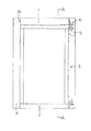
本発明の実施形態を図面に基づいて説明する。図1はドア枠の正面図であって、ドア枠は全体として縦長方形の形状を備えており、鋼板やステンレス板を曲げ加工して製作された、上枠1、下枠(沓摺り)2、左右の縦枠3、4から組立てられている。図2は、図1のドア枠のA−A断面図、図3はドア枠の平面図、図4は縦枠3の上端部に上枠2の端部を挿入させる前の状態を示す斜視図、図5は縦枠の下端部に下枠の端部を挿入させる前の斜視図である。以下、このドア枠の構造について詳細に説明する。
Embodiments of the present invention will be described with reference to the drawings. FIG. 1 is a front view of a door frame. The door frame has a vertically rectangular shape as a whole, and is manufactured by bending a steel plate or a stainless steel plate, and an
上枠1は水平方向に延出する長尺部材であって、開口部の開口幅方向に延出する下面部10と、下面部10の幅方向(長さ方向に直交する方向)両端縁より対向して立ち上がり状に延出する第1見付片11、第2見付片12と、前記第1見付片11、第2見付片12のそれぞれの上端側を対向するように水平状に折り曲げて形成された第1折曲片13、第2折曲片14と、を備えている。下面部10はその幅方向に高さの異なる第1下面部101、第2下面部102、第3下面部103からなり、第1下面部101と第2下面部102との間に第1段部105、第2下面部102と第3下面部103との間に第2段部106が形成されている。
The
なお、本実施の形態では、第1下面部101と第3下面部103は同じ高さの位置にあり、第2下面部102は下側の位置にあり、上枠1は断面視で下向き凸状に形成されている。
In the present embodiment, the first
第1下面部101の長さ方向の両端縁には爪片15、15が突成され、第3下面部103の長さ方向の両端縁には爪片16、16が突成されている。本実施の形態では、爪片15と爪片16は同じ形状、構成であるため、爪片15について説明する。爪片15は、平面視で方形状となっており、基端側には、後述するくさび金具5(本発明のくさび材に相当する。)を差し込むための孔であって、爪片15の突出方向と直交する方向に延びる嵌合孔Sが切り欠き形成されている。また、爪片15の先端側には、ネジ挿入孔Uが形成されており、ネジ挿入孔Uと前記嵌合孔Sとは爪片15の幅方向の中央の位置に設けられている。また、爪片15は、第1下面部101と同じ板厚を備えており、第1下面部101の長さ方向端面から水平状に延出している。
なお、爪片15は、先端側を面取りし、又は、先端側を細く基端側を広幅として全体をテーパー状として、後述する縦枠のスリット孔へ差込み易くしてもよい。また、上枠1の長さ方向の端面18は、第1折曲片13と第1見付片11と第1下面部101(の一部)までの第1端面18aと、第1下面部101(の一部)から第2下面部102を経由して第3下面部103(の一部)までの第2端面18bと、第3下面部103(の一部)と第2見付面12と第2折曲片14までの第3端面18cとからなり、それらは上枠1の長さ方向に直交する同一平面上に揃った位置になっている。また、嵌合孔Sの基端側辺S1は、上枠1の前記端面18と一致する位置か、又は、縦枠3、4の板厚寸法以内で、上枠1の長さ方向の中心側よりに位置している。そのような位置とすることで、後述するくさび金具5が縦枠と横枠に対してくさびとして効果的に働くとともに、枠を組立てた際に、ドア枠の内側から前記嵌合孔Sが見えないようになっている。なお、嵌合孔Sや上枠1の端面加工等は、数値制御型のタレットパンチプレスで行うため、極めて精度良く加工できて、例えば、嵌合孔Sの基端側辺S1を上枠1の端面18から長さ方向の中心よりに例えば0.2mm、又は、0.5mm等、僅かにずらすことが可能である。
Note that the
下枠2は、水平方向に延出する長尺部材であって、開口部の開口幅方向に延出する上面部20と、上面部20の幅方向(長さ方向に直交する方向)両端縁より対向して垂下状に延出する第1見付片21、第2見付片22と、を備えている。なお、上面部20の幅は、前記上枠1の第1下面部101と同じ幅に形成されている。
The
上面部20の長さ方向の両端縁には、爪片25、25が突成されている。突片25の形状については、爪片15と同様であるため、詳細な説明は省略する。
縦枠3は、垂直方向に延出する長尺部材であって、開口部の開口高方向に延出する見込片30と、見込片30の幅方向(長さ方向と直交する方向)両端縁より対向状に延出する第1見付片31、第2見付片32と、第1見付片31、第2見付片32の延出端をそれぞれ折曲してなる第1折曲片33、第2折曲片34と、を備えている。見込片30は、第1見込面301、第2見込面302、第3見込面303とからなり、第1見込面301と第2見込面302との間には第一段部305が、第2見込面302と第3見込面303との間には第2段部306が形成されている。また、第1見込面と第3見込面303はドア枠の正面視において一致する位置にあり、第2見込面302は、前記第1段部305(及び第2段部306)の高さ分だけ、ドア枠方向の内側に形成されている。また、縦枠3の第2見込面302の幅は、上枠1の第2下面部102と同じ幅になっているが、第1見込面301と第3見込面303の幅は、上枠1の第1下面部101と第3下面部103の幅より少し広く形成されている。
The
第1見込面301、第3見込面303の上端部位には、爪片15,16を挿入するスリット孔35,36が、第1見込面301の下端部位には、爪片25を挿入するスリット孔37が形成されている。前記スリット孔35、36、37は、それぞれ爪片15、16、25の断面形状とほぼ一致する大きさとなっている。上枠1の端面18が、横枠3の第1見込面301、第3見込面303に当接する位置まで爪片15、16をしっかり差し込んだときに、縦枠と横枠にガタツキが無いようになっている。また、第1段部305、第2見込面302、第2段部306は、縦枠3の上端から上枠の第1見付片11と第1段部105の高さ分だけ切り欠いて、切欠部309が設けられている。
Slit holes 35, 36 for inserting the
縦枠4は垂直方向に延出する長尺部材であって、基本構成は縦枠3と同様であり、上部に2個、下端部に1個のスリット孔が設けられ、また、上端部は切欠部が形成されている。
The
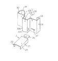
図6に基づいて、くさび金具5の構成を説明する。くさび金具5は金属製のプレス成形品であり、くさび片部51とネジ孔片部52とから側面視略L字状に形成されている。くさび片部51の中央部には、ドア枠の組立時にくさび部として機能する膨出部53が形成され、膨出部53には、くさび片部51から膨出する傾斜角度の大きい案内部531と、傾斜角度のゆるい作用部532とを備えている。また、くさび片部51の先端部は斜めにカットされており、くさび片部51を挿入しやすいようになっている。ネジ孔片部52には、幅方向の中央位置にネジ下孔521が形成されている。本実施例では、ネジ下孔521はセルフタップネジ用の下孔(ネジ径より小さい孔)として設けているが、普通のネジを用いても良く、その場合はタップ加工したネジ孔とすることが出来る。
Based on FIG. 6, the structure of the
このように形成された上枠1、下枠2、縦枠3,4から構成されるドア枠の組立てについて説明する。図1、図3、図7に示すように、上枠1の爪片15と爪片16を、縦枠3のスリット孔35とスリット孔36に、上枠1の第1端面18aと第3端面18cが、縦枠3の第1見込面301と第3見込面303に当接するまで水平方向に挿入する。このとき、上枠1の第2下面部102が、縦枠3の切欠部39の上端面に当接状に載置され、上枠1の第1段部105と第2段部106が、縦枠3の第1段部305と第2段部306と面一となっている。
The assembly of the door frame composed of the
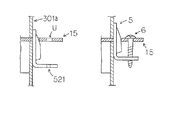
次に、くさび金具5を上枠1の爪片15の嵌合孔Sへ(図1及び図7で下方側から、作業者が手で)押し込み、縦枠3の上端側から(本発明のネジ部材である)タッピングネジ6を爪片15のネジ挿入孔Uに差し入れて(ドライバーで)該タッピングネジのネジ先側(ネジ部分)をくさび金具5のネジ下孔521に螺入させて(捩じ込んで)いくと、くさび金具5が(図1及び図7において)上方へ引き込まれ、くさび金具5が作用位置(くさび材が連結する部材間に強く食い込んだ位置)に確りと食い込むことになる。
Next, the
このとき、縦枠3の第1見込裏面301aと、くさび金具5のくさび片面511が押圧状に当接し、上枠1の爪片15の嵌合孔Sの先端側辺S2と、くさび金具5の作用部532が押圧状に当接して、くさび金具5がくさび材の作用位置にあり、枠同士を強固に連結する。なお、本実施の形態では、くさび金具5の膨出部53に(手で押し込む際の案内面であり、軽く係止するための面ともなる)案内部531と、強く圧入されてくさび作用を発揮する作用部532とで、傾斜角度を変えた形としたが、連続した傾斜面としても良く、くさび作用を発揮する範囲で適宜な形状とすることが可能である。
At this time, the first
さらに、縦枠3と上枠1の爪片16をくさび金具5で連結し、縦枠3と下枠2の爪片25をくさび金具5で連結し、縦枠4と、上枠1と下枠2との連結を同様に行うことで、ドア枠の組立てが完了する。
Further, the claw pieces 16 of the
なお、ドア枠の組立て後に、ドア枠を躯体開口部の所定位置にセットし、溶接や接着材等の適宜手段で固定し、さらに、扉や戸体を吊り込むことになるが、それらは公知の技術手段であり、また、実際のドア枠には工場出荷時に丁番や錠受部の穴加工や下地材等が取付けられているが、それらも公知のものであるため、その説明は省略する。 In addition, after the door frame is assembled, the door frame is set at a predetermined position of the housing opening, fixed by appropriate means such as welding or adhesive, and the door or door body is suspended. In addition, the actual door frame has hinges, holes for the lock receiving portion, and base material attached to the actual door frame at the time of shipment from the factory. To do.
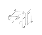
本発明の連結構造は、種々の形状のドア枠の組立てに採用でき、例えば、図8に示すような形状でも良く、枠材の形状は本実施例に限定されるものではない。なお、本発明は主に工事現場で組立てることを目的としたもので、縦枠の見付面に対して横枠の見付面がドア枠の見込方向の内側に位置した状態(いわゆる「面落ち」)のドア枠に適用するのがより好適である。 The connection structure of the present invention can be used for assembling door frames having various shapes. For example, the shape shown in FIG. 8 may be used, and the shape of the frame material is not limited to this embodiment. The present invention is mainly intended to be assembled at a construction site, and the horizontal frame finding surface is positioned inside the door frame looking direction with respect to the vertical frame finding surface (so-called “surface”). It is more preferable to apply to the door frame of “drop”.
本実施の形態では、横枠の爪片にネジ挿入孔(ネジ外径より大きい孔)を設け、くさび金具にネジ下孔(ネジ外径より小さい孔)を設けたが、これを反対にしたものでも良い。その場合を図1で説明すると、くさび金具を縦枠の上端側から差し込み、タッピングネジを同じ上端側から捩じ込んで、くさび金具をネジの回転で押し下げる構成となる。また、下枠の連結は本実施例を用いて、上枠の連結は孔径を反対としたものとすると、くさび金具がすべて上側から差し込まれるため、不用意にくさび金具が抜け落ちる恐れがない。また、本実施の形態では、上枠と下枠に爪片を設ける構成としたが、縦枠に爪片を設け、上下の枠にスリット孔を設けても良い。また、ドア枠の形状や見込方向の厚さに応じて、爪片の数や位置、形状を適宜変更することが可能であり、複数の爪片を並行する位置ではなく、直行位置や、段違い位置、45度の角度で設け、又は、爪片をL字状するなどしても良い。 In this embodiment, a screw insertion hole (a hole larger than the screw outer diameter) is provided in the claw piece of the horizontal frame, and a screw lower hole (a hole smaller than the screw outer diameter) is provided in the wedge metal fitting. Things can be used. The case will be described with reference to FIG. 1. A wedge metal fitting is inserted from the upper end side of the vertical frame, a tapping screw is screwed in from the same upper end side, and the wedge metal fitting is pushed down by rotation of the screw. Further, if the lower frame is connected using the present embodiment and the upper frame is connected with the opposite hole diameter, the wedge metal fittings are all inserted from the upper side, so that the wedge metal fittings are not accidentally dropped off. In the present embodiment, the upper and lower frames are provided with claw pieces. However, the vertical frame may be provided with claw pieces and the upper and lower frames may be provided with slit holes. In addition, the number, position, and shape of the claw pieces can be changed as appropriate according to the shape of the door frame and the thickness in the expected direction. The position may be provided at an angle of 45 degrees, or the nail piece may be L-shaped.
本発明は、ドア(開き戸)の枠に限定されるものではなく、例えば、引戸用の枠にも使用可能である。 The present invention is not limited to a frame of a door (a swing door), and can be used for a frame for a sliding door, for example.
1 上枠
10 下面部
11 第1見付片
15、16 爪片
18 端面
S 嵌合孔
S1 基端側辺
S2 先端側辺
U ネジ挿入穴
2 下枠
20 上面部
25 爪片
3 縦枠
30 見込片
301 第1見込片
301a 第1見込裏面
302 第2見込片
303 第3見込片
35、36、37 スリット孔
4 縦枠
5 くさび金具
51 くさび片部
511 くさび片面
52 ネジ孔片部
521 ネジ下孔
53 膨出部
531 案内部
532 作用部
6 タッピングネジ
DESCRIPTION OF
Claims (2)
Priority Applications (1)
| Application Number | Priority Date | Filing Date | Title |
|---|---|---|---|
| JP2013065302A JP6244095B2 (en) | 2013-03-27 | 2013-03-27 | Door frame connection structure |
Applications Claiming Priority (1)
| Application Number | Priority Date | Filing Date | Title |
|---|---|---|---|
| JP2013065302A JP6244095B2 (en) | 2013-03-27 | 2013-03-27 | Door frame connection structure |
Publications (2)
| Publication Number | Publication Date |
|---|---|
| JP2014190011A true JP2014190011A (en) | 2014-10-06 |
| JP6244095B2 JP6244095B2 (en) | 2017-12-06 |
Family
ID=51836560
Family Applications (1)
| Application Number | Title | Priority Date | Filing Date |
|---|---|---|---|
| JP2013065302A Active JP6244095B2 (en) | 2013-03-27 | 2013-03-27 | Door frame connection structure |
Country Status (1)
| Country | Link |
|---|---|
| JP (1) | JP6244095B2 (en) |
Cited By (2)
| Publication number | Priority date | Publication date | Assignee | Title |
|---|---|---|---|---|
| JP2020076315A (en) * | 2020-02-17 | 2020-05-21 | Ykk Ap株式会社 | Fittings |
| JP2020076314A (en) * | 2020-02-17 | 2020-05-21 | Ykk Ap株式会社 | Fittings |
Citations (4)
| Publication number | Priority date | Publication date | Assignee | Title |
|---|---|---|---|---|
| JPS55116184U (en) * | 1979-02-10 | 1980-08-16 | ||
| JPS5885072U (en) * | 1981-12-07 | 1983-06-09 | 三協アルミニウム工業株式会社 | Shape connection device |
| JPH0347990U (en) * | 1989-09-12 | 1991-05-07 | ||
| JP2001280013A (en) * | 2000-03-31 | 2001-10-10 | Ykk Architectural Products Inc | Bay window |
-
2013
- 2013-03-27 JP JP2013065302A patent/JP6244095B2/en active Active
Patent Citations (4)
| Publication number | Priority date | Publication date | Assignee | Title |
|---|---|---|---|---|
| JPS55116184U (en) * | 1979-02-10 | 1980-08-16 | ||
| JPS5885072U (en) * | 1981-12-07 | 1983-06-09 | 三協アルミニウム工業株式会社 | Shape connection device |
| JPH0347990U (en) * | 1989-09-12 | 1991-05-07 | ||
| JP2001280013A (en) * | 2000-03-31 | 2001-10-10 | Ykk Architectural Products Inc | Bay window |
Cited By (4)
| Publication number | Priority date | Publication date | Assignee | Title |
|---|---|---|---|---|
| JP2020076315A (en) * | 2020-02-17 | 2020-05-21 | Ykk Ap株式会社 | Fittings |
| JP2020076314A (en) * | 2020-02-17 | 2020-05-21 | Ykk Ap株式会社 | Fittings |
| JP7036849B2 (en) | 2020-02-17 | 2022-03-15 | Ykk Ap株式会社 | Joinery |
| JP7036848B2 (en) | 2020-02-17 | 2022-03-15 | Ykk Ap株式会社 | Joinery |
Also Published As
| Publication number | Publication date |
|---|---|
| JP6244095B2 (en) | 2017-12-06 |
Similar Documents
| Publication | Publication Date | Title |
|---|---|---|
| US20180066691A1 (en) | Frame assembly body and casing | |
| US9212675B2 (en) | Fastening arrangement and method | |
| US9051778B2 (en) | Lineal connector and template | |
| JP6244095B2 (en) | Door frame connection structure | |
| KR102441224B1 (en) | Frame corner piece assembly structure that can stably maintain the combined state without shaking | |
| JP4324151B2 (en) | Guide member and joining structure for joining wood members | |
| KR20110088861A (en) | Furniture frame corner connection implement | |
| JP5087054B2 (en) | Joining structure and joinery | |
| JP5495993B2 (en) | Body edge, body edge receiving member and base material | |
| JP5785652B1 (en) | Fixture frame mounting bracket | |
| JP5760068B2 (en) | Joint fittings and joint structures for wooden buildings | |
| CN211448091U (en) | Bar handle structure | |
| JP4373465B2 (en) | Joining method | |
| JP2008014477A (en) | Pipe clamp fixing structure | |
| JP6472648B2 (en) | Wooden horizontal bracket | |
| KR102101471B1 (en) | A frame fixing device formed on a corner connector for a frame | |
| JP4173463B2 (en) | Bonding bracket for building | |
| KR20190094050A (en) | Connection brackets for connecting frame bars in three axial directions at the same time | |
| EP2713063B1 (en) | Mechanical joint for reversible coupling of two or more elements and joining | |
| KR102256088B1 (en) | A frame fixing device formed on a corner connector for a frame | |
| JP6490143B2 (en) | Mounting device | |
| JP2005200859A (en) | Joining pin and joining structure using this joining pin | |
| JP2507339Y2 (en) | Connection structure of panel to joiner | |
| JP6519744B2 (en) | Outer plate connection fitting for grain dryer and method of mounting the same | |
| JP2021001621A (en) | Connecting member and frame connecting structure |
Legal Events
| Date | Code | Title | Description |
|---|---|---|---|
| A621 | Written request for application examination |
Free format text: JAPANESE INTERMEDIATE CODE: A621 Effective date: 20151224 |
|
| A977 | Report on retrieval |
Free format text: JAPANESE INTERMEDIATE CODE: A971007 Effective date: 20161019 |
|
| A131 | Notification of reasons for refusal |
Free format text: JAPANESE INTERMEDIATE CODE: A131 Effective date: 20161026 |
|
| A521 | Written amendment |
Free format text: JAPANESE INTERMEDIATE CODE: A523 Effective date: 20161214 |
|
| A131 | Notification of reasons for refusal |
Free format text: JAPANESE INTERMEDIATE CODE: A131 Effective date: 20170511 |
|
| A521 | Written amendment |
Free format text: JAPANESE INTERMEDIATE CODE: A523 Effective date: 20170525 |
|
| TRDD | Decision of grant or rejection written | ||
| A01 | Written decision to grant a patent or to grant a registration (utility model) |
Free format text: JAPANESE INTERMEDIATE CODE: A01 Effective date: 20171026 |
|
| A61 | First payment of annual fees (during grant procedure) |
Free format text: JAPANESE INTERMEDIATE CODE: A61 Effective date: 20171113 |
|
| R150 | Certificate of patent or registration of utility model |
Ref document number: 6244095 Country of ref document: JP Free format text: JAPANESE INTERMEDIATE CODE: R150 |