JP6472648B2 - Wooden horizontal bracket - Google Patents
Wooden horizontal bracket Download PDFInfo
- Publication number
- JP6472648B2 JP6472648B2 JP2014243530A JP2014243530A JP6472648B2 JP 6472648 B2 JP6472648 B2 JP 6472648B2 JP 2014243530 A JP2014243530 A JP 2014243530A JP 2014243530 A JP2014243530 A JP 2014243530A JP 6472648 B2 JP6472648 B2 JP 6472648B2
- Authority
- JP
- Japan
- Prior art keywords
- hardware
- plate
- wooden
- joint
- wooden horizontal
- Prior art date
- Legal status (The legal status is an assumption and is not a legal conclusion. Google has not performed a legal analysis and makes no representation as to the accuracy of the status listed.)
- Active
Links
- 239000002184 metal Substances 0.000 claims description 51
- 239000000463 material Substances 0.000 claims description 9
- 239000002023 wood Substances 0.000 claims description 4
- 238000013459 approach Methods 0.000 claims description 2
- 238000010276 construction Methods 0.000 description 6
- 238000005452 bending Methods 0.000 description 1
- 238000003780 insertion Methods 0.000 description 1
- 230000037431 insertion Effects 0.000 description 1
- 230000002452 interceptive effect Effects 0.000 description 1
- 239000007787 solid Substances 0.000 description 1
Images


Description
本発明は、土台、梁、柱などの側面に、大引き、梁などの木製横架材の端面(木口)を受けて接合する場合などに使用する、木製横架材の受け金物に関する。 The present invention relates to a wooden horizontal member receiving metal used for receiving and joining the end face (cut end) of a wooden horizontal member such as a large draw or a beam to side surfaces such as a base, a beam, and a column.
従来、土台の側面に大引きの端面を接合する場合、一旦大引きを所定の位置に受けて、その状態を維持して固定するために、大引きを受けるU字状(横コ字状)の受け部が必須で、かつ、土台に金物を固定するための受け部に直行する向きの固定部が必要であった(特許文献1〜3)。この場合、突出部が多い立体的な形状となり、搬送の際に、重ねることができず、かさばる問題点があった。
また、大引きの高さ調整のために、「大引きの底部側を受ける側の部材」を「他の部材」から分離可能として、「大引きの底部側を受ける側の部材」を上下動させる提案もあった(特許文献3)。
Conventionally, when joining the end face of a large pull to the side of the foundation, the large pull is once received at a predetermined position, and the U-shaped (horizontal U-shaped) that receives the large pull in order to maintain and fix the state The receiving part is essential, and a fixing part in a direction perpendicular to the receiving part for fixing the hardware to the base is necessary (
In order to adjust the height of the large pull, the “member on the side receiving the bottom of the large pull” can be separated from the “other member”, and the “member on the side receiving the bottom of the large pull” is moved up and down. There was also a proposal (patent document 3).
受け部と固定部とを分離する提案では、組み立てが容易でなく、施工効率が悪い問題点があった。そこで、この発明は、分解して搬送効率を高め、施工現場での組み立てが容易であり、施工効率を損なわないことを課題とする。なお、土台と大引きとの接合の際に使用する金物に顕著に表れる問題点であるが、梁と小梁、柱と梁など他の接合部分でも同様である。 In the proposal of separating the receiving part and the fixing part, there is a problem that assembly is not easy and construction efficiency is poor. Then, this invention makes it a subject that it decomposes | disassembles and raises conveyance efficiency, is easy to assemble at a construction site, and does not impair construction efficiency. This is a problem that appears prominently in the hardware used when joining the base and the large pull, but the same applies to other joints such as beams and small beams and columns and beams.
本発明は、土台などの第一木製部材に固定する第二金物と、大引きなどの木製横架材を受ける第一金物とに分離して、第一金物と第二金物とを接合凹部と接合凸部とで緩く嵌合したので、前記問題点を解決した。 The present invention separates a second hardware to be fixed to a first wooden member such as a base and a first hardware to receive a wooden horizontal member such as a large pull, and the first hardware and the second hardware are joined to each other. The problem was solved because it was loosely fitted with the joint projection.
即ち、この発明は、第一木製部材の側面に、木製横架材の端面を接合する際に使用する金物であって、以下のように構成することを特徴とする木製横架材の受け金物である。
(1) 前記木製横架材の下面を受ける第一金物と、前記第一金物に連結して、前記第一木製部材に固定する第二金物とから構成する。
(2) 前記第一金物は、前記木製横架材の下面を受ける横板と、前記横板の両端に連設した両縦板とからなる略U字状とし、前記縦板の上端部を第一接合部とする。
(3) 前記第二金物は、前記第一木製部材の側面に固定される固定板と、前記固定板に連設する連結板とからなり、前記連結板の先端部に第二接合部を形成する。
(4) 前記第一接合部又は前記第二接合部の何れか一方に接合凹部を形成し、他方に前記接合凹部に緩く嵌挿される接合凸部を形成する。
That is, this invention is a hardware used when joining the end surface of the wooden horizontal member to the side surface of the first wooden member, and is configured as follows. It is.
(1) A first hardware that receives the lower surface of the wooden horizontal member and a second hardware that is connected to the first hardware and fixed to the first wooden member.
(2) the first hardware includes a horizontal plate for receiving the lower surface of the wooden horizontal members, and the transverse plate substantially U-shaped consisting of a double vertical plate provided continuously across the, the upper end of the vertical plate This is the first joint.
(3) the second hardware includes a fixed plate fixed to the side surface of the first wood member, consists of a connecting plate to continuously provided to the fixing plate, forming a second bonding portion to the distal end of the connecting plate To do.
(4) A bonding recess is formed in one of the first bonding portion and the second bonding portion, and a bonding protrusion that is loosely inserted into the bonding recess is formed in the other.
また、他の発明は、第一木製部材の側面に、木製横架材の端面を接合する際に使用する金物であって、以下のように構成することを特徴とする木製横架材の受け金物である。
(1) 前記木製横架材の下面を受ける第一金物と、前記第一金物に連結して、前記第一木製部材に固定する第二金物とから構成した。
(2) 前記第一金物は、前記木製横架材の下面を受ける横板と、前記横板の両端に連設した両縦板とからなる略U字状とし、前記縦板の上端部を第一接合部とした。
(3) 前記第二金物は、前記第一木製部材の側面に固定される固定板と、前記固定板に連設する連結板とからなり、前記連結板の先端部に第二接合部を形成した。
(4) 前記第一接合部と前記第二接合部とは着脱可能な構造とした。
(5) 前記第一接合部の前記木製横架材側の面に、外側に向けて屈曲する横方向の屈曲段部を形成し、前記屈曲段部に、前記第二金物の連結板の下縁係止可能に形成した。
(6) 前記屈曲段部に、前記連結板が係止した状態で、前記縦板の前記木製横架材側の面と、前記連結板の前記木製横架材側の面とを、略面一に形成した。
According to another aspect of the present invention, there is provided a hardware for use in joining the end face of the wooden horizontal member to the side surface of the first wooden member, the wooden horizontal member having the following structure. It is a hardware.
(1) wherein the first hardware for receiving the lower surface of the wooden horizontal members, coupled to said first hardware, and composed of a second hardware to be fixed to said first wooden member.
(2) the first hardware includes a horizontal plate for receiving the lower surface of the wooden horizontal members, and the transverse plate substantially U-shaped consisting of a double vertical plate provided continuously across the, the upper end of the vertical plate and the first joint portion.
(3) the second hardware includes a fixed plate fixed to the side surface of the first wood member, consists of a connecting plate to continuously provided to the fixing plate, forming a second bonding portion to the distal end of the connecting plate I did .
(4) the the first joint portion and the second joint portion has a detachable structure.
(5) Form a laterally bent step that bends outward on the surface of the first joint portion on the side of the wooden horizontal member, and the bent step is below the connection plate of the second hardware. It was formed so that the edge could be locked.
(6) The surface of the vertical plate on the side of the wooden horizontal member and the surface of the side of the connecting plate on the side of the wooden horizontal member in a state where the connecting plate is locked to the bent stepped portion. Formed in one .
また、前記各発明において、以下のように構成する木製横架材の受け金物である。
(1) 接合凹部を貫通孔として、接合凸部を中空孔を有する筒状に形成し、前記貫通孔と中空孔とに、ビス類を挿入可能とした。
(2) 前記接合凸部は、第二金物の一面から他面側に向けて前記貫通孔に挿入され、挿入状態で、前記接合凸部の先端は、前記第二金物の他面から突出しない形状とした。
Moreover, in each said invention, it is a receiving material of the wooden horizontal member comprised as follows.
(1) The joint concave portion is used as a through hole, and the joint convex portion is formed in a cylindrical shape having a hollow hole, so that screws can be inserted into the through hole and the hollow hole.
(2) The joint convex portion is inserted into the through hole from one surface of the second hardware toward the other surface, and in the inserted state, the tip of the joint convex portion does not protrude from the other surface of the second hardware. Shaped.
また、前記各発明において、以下のように構成する木製横架材の受け金物である。
(1) 第二金物を、平面視で、固定板と指示板連結板とを略直角とした平面視で略L字状に形成した。
(2) 前記第二金物は、前記連結板に対して、前記固定板が近づき平面視で第一金物内に納まる第一配置と、前記固定板が離れて平面視で前記第一金物から突出する第二配置をとれるように構成した。
Moreover, in each said invention, it is a receiving material of the wooden horizontal member comprised as follows.
(1) The second hardware was formed in a substantially L shape in plan view with the fixing plate and the indicator plate connecting plate being substantially perpendicular .
(2) The second hardware has a first arrangement in which the fixing plate approaches the connection plate and fits in the first hardware in a plan view, and the fixing plate separates and protrudes from the first hardware in a plan view. The second arrangement is configured to be taken.
前記における「第一木製部材の側面」は主に、土台や梁などの木製の横架材の垂直面を指すが、柱(通し柱、管柱、間柱などを含む)の垂直面も可能である。 The above-mentioned “side surface of the first wooden member” mainly refers to a vertical surface of a wooden horizontal member such as a base or a beam, but a vertical surface of a column (including a through column, a tube column, a space column, etc.) is also possible. .
また、前記における「木製横架材の端面」は木製横架材の木口を指し、木製横架材は、第一木製部材が土台の場合は大引きであり、第一木製部材が桁、胴差の場合には梁、第一木製部材が梁の場合には小梁などが該当する。 In addition, the “end surface of the wooden horizontal member” in the above refers to the mouth of the wooden horizontal member, and the wooden horizontal member is a large pull when the first wooden member is a base, and the first wooden member is a girder and a trunk. In the case of a difference, a beam, and in the case where the first wooden member is a beam, a small beam or the like is applicable.
また、前記における「緩く嵌合する」とは、接合凹部に接合凸部を嵌挿した際に、摩擦により、多少動かしても第一金物と第二金物との組み立て状態を維持するが、作業者が手動で外す方向に操作をすれば容易に嵌合を解くことができる程度に取付られている状態を指す。また、接合凹部に接合凸部を嵌挿する作業も、作業者が手動で容易に嵌合できる状態である。 In addition, “loosely fit” in the above means that when the joint convex portion is inserted into the joint concave portion, the assembled state of the first hardware and the second hardware is maintained even if it is moved slightly by friction. It indicates a state in which it is attached to such an extent that it can be easily disengaged if the person manually operates in the direction to remove it. Moreover, the operation | work which inserts a joining convex part in a joining recessed part is also a state which an operator can fit easily manually.
この発明は、木製横架材を受ける第一金物と、第一金物に連結して第一木製部材に固定する2つの第二部材とから構成し、第一金物と第二金物とは嵌合凸部と嵌合凹部とが緩く嵌合するので、作業者が手で組み立て、分解が容易である。したがって、かさばる立体形状の金物であっても第一金物と第二金物とに分解することにより、工場から現場への搬送、現場での保管などでスペースを省略できる。また、嵌合凸部と嵌合凹部とで嵌合させるので、第一金物と第二金物との組み立てに際して、位置合わせが容易であり、現場作業を効率化できる。 The present invention comprises a first hardware that receives a wooden horizontal member and two second members that are connected to the first hardware and fixed to the first wooden member, and the first hardware and the second hardware are fitted together. Since the convex portion and the fitting concave portion are loosely fitted, the operator can easily assemble and disassemble it by hand. Therefore, even if it is a bulky three-dimensional hardware, by disassembling it into the first hardware and the second hardware, the space can be omitted for transportation from the factory to the site, storage at the site, and the like. Moreover, since it is made to fit by a fitting convex part and a fitting recessed part, at the time of an assembly of a 1st metal fitting and a 2nd metal fitting, position alignment is easy and field work can be made efficient.
図面に基づき、この発明の受け金物40を大引き受けに適用する実施形態を説明する。すなわち、木製横架材を大引き50とし、第一木製部材を土台45とした実施態様である。
An embodiment in which the metal fitting 40 of the present invention is applied to large acceptance will be described with reference to the drawings. That is, this is an embodiment in which the wooden horizontal member is the
1.受け金物40の構成
1. Structure of the
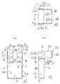
(1) この発明の受け金物40は、主に大引き50(木製横架材)の下面51a側を受ける1つの第一金物1と、第一金物1と連結して土台45(木製横架材)に接合する2つの第二金物20、20とから構成する(図1〜図3、図5、図6)。
(1) The
(2) 先ず、第一金物1について説明する。第一金物1は、大引き50の下面51aを受ける横板2と、大引き50の両側面52、52に沿って配置される縦板4、4とからなる。すなわち、大引き50の幅方向に対応した幅を有する横板2の両端に、略直角に縦板4、4をそれぞれ連設してた形状で、一体の側面視略U字状(略横コ字状)の第一金物1とする。通常は、厚さt1、幅L1の帯状の長い板材を屈曲して、長さ(大引き50の幅に対応)D1の横板2、長さ(高さ。通常、大引き50の高さより若干短い)H1の縦板4、4を形成する。
ここで、縦板4において、並列した縦板4、4が向き合う面(横板2が位置する側)を内面5、反対側を外面5aとする。また、縦板4において、使用する大引き50の長さ方向の中心側が位置する側の縁を一縁7として、反対側(大引き50の端面53側=土台45側)の縁を他縁7aとする。
(2) First, the
Here, in the
(3) 縦板4、4の上部で、上端6から距離H10の位置に、横方向(幅L1を横断する方向)に段差部8を形成して、縦板4の上端部を距離L10だけ外側に平行移動させて連結部10を形成する。連結部10は残余の縦板4(連結部10と段差部8を除いた縦板4)と平行に形成される。したがって、両縦板4、4で、連結部10、10間の距離は、
D1+2×L10
で形成される。
(3) At the upper part of the
D1 + 2 × L10
Formed with.
(4) 連結部10、10に、貫通孔を形成してかつ貫通孔の開口縁を筒状に突出させて接合凸部12を形成する。接合凸部12はバーリング加工などで形成する。接合凸部12は、両縦板4、4の連結部10、10が対向する方向(内向き)、すなわち段差部8の上方に形成する。また、接合凸部12は、連結部10で、幅L1方向の略中央部に位置し、上下に2つ形成する。
また、両縦板4、4の下部で、幅L1方向の略中央部に、下部透孔15を形成する。
(4) The connecting
In addition, a lower through
(5) 次ぎに、第二金物20について説明する。第二金物20は、厚さt2で幅L2の帯状の板材を屈曲して、長い連結板21と短い固定板28とからなる平面視L字状に形成する。
連結板21の幅(高さ)L2は、縦板4の連結部10の高さH10と略同一に形成され、連結板21の材厚t2は段差部8の突出長さL10とほぼ同一に形成される(図1(a))。すなわち、
L2≒H10、t2≒L10
で形成される。
連結板21の先端部で、第一金物1の連結部10に当接する部分に、2つの貫通孔(接合凹部)26、26を上下(幅L2方向)に2つ形成する。貫通孔26は、接合凸部12に対応した位置に形成し、かつ貫通孔26に接合凸部12の筒状突起を挿入した際に、緩く嵌挿して、摩擦などで嵌合状態を保ち、また、手で操作すれば容易に嵌合状態を解除できる程度の嵌挿状態に形成する。
また、固定板28にねじやピンなどを挿入する固定透孔29、29を4つづつ形成する。
(5) Next, the
The width (height) L2 of the connecting
L2≈H10, t2≈L10
Formed with.
Two through holes (joining recesses) 26 and 26 are formed in the top and bottom (in the direction of the width L2) at a portion of the connecting
In addition, four fixed through
(6) 以上のようにして形成した第一金物1の連結部10に、第二金物20の連結板21の先端部を重ねる。
この際、第二金物20の固定板28、28は両第二金物20、20が互いに離れる方向となるように配置する。すなわち、第二金物20の連結板21の他面22aを、第一金物1の縦板4の連結部10で、縦板4の内面5に当て、固定板28の先端が、縦板4、4のから水平方向で離れるように突出しているように、配置する(図1、図2(a)(b)。外使い)。
また、この状態で、第一金物1の連結部10の接合凸部12、12の筒状突起が、第二金物20の連結板21の貫通孔26、26に緩く嵌挿される(図3(a)(b))。接合凸部12と貫通孔26とが緩く嵌挿され、かつ、第一金物1の連結部10の内面5(縦板4の内面5)と第二金物20の連結板21の一面22(固定板28側の面)が密着した状態で、 L2≒H10、t2≒L10 で形成されているので、
・第二金物20の連結板21の下縁23が第一金物1の段差部8の上縁に位置し、
・第二金物20の連結板21の他面22a(固定板28側とは反対の面)と、第一金物1の縦板4の内面5とが面一に配置され、
・第二金物20の連結板21の上縁23が、第一金物1の連結部10の上縁6と略同じ高さに配置され、
・第二金物20の連結板21の先端縁24が、第一金物1の縦板4の一縁7と平面視で略一致するように配置される。
となる。
また、この状態で、第一金物1の連結部10の内面5から接合凸部12の突出高さL12は、第二金物20の貫通孔26の深さ(すなわち、材厚t2)よりも小さく形成されているので、接合凸部12の先端13は、連結板21の他面22aよりL30だけ内側に位置して、貫通孔26内に納まっている(図3(b))。したがって、第一金物1と第二金物20とを組付けた状態で、金物40に衝撃が与えられた場合であっても、接合凸部12の筒状突起の先端13が打撃され、摩擦に抗して不用意に抜け外れたり、あるいは接合凸部12の筒状突起の先端13が打撃屈曲され、貫通孔(接合凹部)26から不用意に外れなくなることを防止できる。
(6) The front end of the
At this time, the fixing
Further, in this state, the cylindrical projections of the
-The
The
The
The
It becomes.
Further, in this state, the protrusion height L12 of the
(7) 以上のようにして、大引き用の受け金物40を構成する(図1、図2)。
(7) In the manner described above, the large
2.受け金物40の使用
2. Use of
(1) 受け金物40は、第一金物1と第二金物20とを分離した状態で(図1)、工場から施工現場まで搬送される。この際、第一金物1、1毎、第二金物20、20毎に重ねて梱包できるので、嵩を小さくして、搬送コストを軽減できる。
(1) The
(2) また、施工現場では、第一金物1の接合凸部12、12を、第二金物20の貫通孔26、26に挿入するだけで緩く嵌合できるので、作業者は工具を使用することなく、簡単に、受け金物40に組み立てできる。また、万一、第二金物20の取付方向を間違えた場合であっても、作業者は簡単に手で外して、正しい向きに変更できる。
(2) Moreover, since it can be loosely fitted only by inserting the joint
(3) コンクリート製の基礎43上に土台(木製第一部材)45がアンカーボルト(図示していない)などで、固定されている。
組み立てた受け金物40を、第二金物20の固定板28の固定透孔29、29からビスを打ち、土台45の側面46に固定できる。また、大引き50を土台45に合わせ、受け金物40の第一金物1の横板2に大引き50の下面51aを載せる。この状態で、第二金物20の連結板21の他面22a(固定板28側とは反対の面)と、第一金物1の縦板4の内面5とが面一に形成されているので、大引き50の両側面52、52は受け金物40(第二金物20の連結板21の他面22a及び第一金物1の縦板4の内面5)に密着できる。
続いて、第一金物1の縦板4の外面5a側から下部透孔15、15にビスを大引き50に向けて打ち、また、接合凸部12、12でもビスを大引き50向けて打つ。以上のようにして、大引き50を土台45に固定できる(図6(a)(b))。
(3) A base (first wooden member) 45 is fixed on a
The assembled
Subsequently, a screw is hit toward the
3.他の第二金物20の配置と受け金物40の使用
3. Arrangement of other
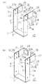
前記実施態様において、同じ構造の第一金物1、第二金物20、20を使用して、他の受け金物40を構成することもできる(図4、図5、図7)。
In the said embodiment, the other metal fitting 40 can also be comprised using the
すなわち、前記実施例では、第二金物20の連結板21の他面22aを、第一金物1の縦板4の連結部10で、縦板4の内面5に当てたが、第二金物20の連結板21の一面22を、第一金物1の縦板4の連結部10で、縦板4の内面5に当てて、固定板28、28の先端が、平面視で、縦板4、4間に位置して、互いに向き合うように配置する(図4、図5。内使い)。
That is, in the said Example, although the
このような内使いの場合は、受け金物40を土台45の側面46に当てて、先ず、第二金物20の固定板28、28の固定透孔29、29からビス56、56を打ち、土台45に受け金物40を固定する。その後、受け金物40に大引き50を載置して、固定する(図7)。
In such an internal use, the
また、このような内使いであれば、取付予定の大引き50(または梁など)付近に第二金物20の固定板28、28に干渉していまう他の金物や木製部材などが存在した場合であっても、施工が可能となる。また第一木製部材として通し柱などの柱に適用した場合にも、柱の幅内に受け金物40(特に、第二金物20の固定板40)が収まり施工が可能となる(図示していない)。
In addition, in the case of such internal use, when there are other hardware or wooden members interfering with the fixing
4.他の実施態様 4). Other embodiments
(1) 前記実施態様において、接合凸部12と貫通孔26は2組配置したので、組み立てる際に、位置合わせが容易となるが、少なくとも1組形成すれば良い。
(1) In the said embodiment, since 2 sets of the joining
(2) また、前記実施態様において、第一金物1の接合凸部12は、バーリング加工などで形成する内側に貫通孔(中空部)を有する筒状突起としたが、貫通孔を使ってビスなどの取付に使用しなければ、貫通孔を詰めた中実の突起ととすることもできる(図示していない)。
(2) Moreover, in the said embodiment, although the joining
(3) また、前記実施態様において、第二金物20の接合凹部を貫通孔26としたが、一面22から他面22aに貫通しない、他面22aに底を有する穴とすることもできる(図示していない)。この場合には、第二金物20を、固定板28、28を内側に向けての使用(図4、図5)をすることはできない。
(3) Moreover, in the said embodiment, although the joining recessed part of the 2nd metal fitting 20 was made into the through-
(4) 前記実施例において、第一部材1の縦板4の段差部8は、第二金物20の連結板21の下縁23aの直下に設けたので、面一に形成される「連結板21の一面24」と「縦板4の内面5」とを広く形成されて好ましいが、第一部材1の縦板4で第二金物20の連結板21の下縁23aの下方であれば、位置は任意である(図示していない)。
(4) In the said Example, since the level | step-
(5) また、前記実施態様において、縦板4に段差部8を形成したので、第一金物1の縦板4の内面5と第二金物20の連結板21の内面22とを面一に形成でき、大引き50の側面52と密着できるので好ましいが、段差部8を省略することもできる(図示していない)。
(5) Moreover, in the said embodiment, since the level | step-
(6) また、前記実施態様において、第一金物1の縦板4に段差部8を省略して、縦板4をフラットな形状として、第二金物20の連結板21で、縦板4の他縁7aに沿った位置に、段差部25を縦に形成する(図8)。
この場合も、第二金物20の固定板28、28を、外使いと内使いとの二通りの配置とすることができる(図8(a)(b))。
第一の配置では、第二金物20の固定板28、28は両第二金物20、20が互いに離れる方向となるように配置する。すなわち、第二金物20の連結板21の他面22aを、第一金物1の縦板4の連結部10で、縦板4の内面5に当て、固定板28の先端が、縦板4、4のから水平方向で離れるように突出しているように、配置する(図8(a))。この場合には、縦板4の内面5と連結板21の一面22とは面一に形成されるので、大引き50の側面52に密着できる。
また。第二の配置では、第二金物20の連結板21の一面22を、第一金物1の縦板4の連結部10で、縦板4の内面5に当てて、固定板28、28の先端が、平面視で、縦板4、4間に位置して、互いに向き合うように配置する(図8(b))。この場合には、大引き受け金物50で、縦板4の内面5から第二金物20の連結板21の先端側が厚さt2分だけ突出する。
(6) Moreover, in the said embodiment, the level | step-
Also in this case, the fixing
In the first arrangement, the fixing
Also. In the second arrangement, one
1 第一金物
2 第一金物の横板
3 横板の上面
4 第一金物の縦板
5 縦板の内面
5a 縦板の外面
6 縦板の上端
7 縦板の一縁
7a 縦板の他縁
8 縦板の段差部
10 縦板の連結部
12 縦板の接合凸部
13 接合凸部の先端
15 下部透孔
20 第二金物
21 第二金物の連結板
22 連結板の内面
22a 連結板の外面
23 連結板の上縁
23a 連結板の下縁
24 連結板の先端縁
25 連結板の段差部
26 連結板の貫通孔(接合凹部)
28 第二金物の固定板
29 固定板の固定透孔
40 大引き受け金物(木製横架材の受け金物)
45 土台
46 土台の側面
50 大引き
51 大引きの上面
51a 大引きの下面
52 大引きの側面
53 大引きの端面(木口)
56 ビス
DESCRIPTION OF
28 Fixing plate for second metal fitting 29 Fixing through
45
56 screws
Claims (4)
(1) 前記木製横架材の下面を受ける第一金物と、前記第一金物に連結して、前記第一木製部材に固定する第二金物とから構成する。
(2) 前記第一金物は、前記木製横架材の下面を受ける横板と、前記横板の両端に連設した両縦板とからなる略U字状とし、前記縦板の上端部を第一接合部とする。
(3) 前記第二金物は、前記第一木製部材の側面に固定される固定板と、前記固定板に連設する連結板とからなり、前記連結板の先端部に第二接合部を形成する。
(4) 前記第一接合部又は前記第二接合部の何れか一方に接合凹部を形成し、他方に前記接合凹部に緩く嵌挿される接合凸部を形成する。 A hardware used for joining the end face of a wooden horizontal member to the side surface of the first wooden member, the wooden horizontal member receiving metal having the following structure.
(1) A first hardware that receives the lower surface of the wooden horizontal member and a second hardware that is connected to the first hardware and fixed to the first wooden member.
(2) the first hardware includes a horizontal plate for receiving the lower surface of the wooden horizontal members, and the transverse plate substantially U-shaped consisting of a double vertical plate provided continuously across the, the upper end of the vertical plate This is the first joint.
(3) the second hardware includes a fixed plate fixed to the side surface of the first wood member, consists of a connecting plate to continuously provided to the fixing plate, forming a second bonding portion to the distal end of the connecting plate To do.
(4) A bonding recess is formed in one of the first bonding portion and the second bonding portion, and a bonding protrusion that is loosely inserted into the bonding recess is formed in the other.
(1) 前記木製横架材の下面を受ける第一金物と、前記第一金物に連結して、前記第一木製部材に固定する第二金物とから構成した。
(2) 前記第一金物は、前記木製横架材の下面を受ける横板と、前記横板の両端に連設した両縦板とからなる略U字状とし、前記縦板の上端部を第一接合部とした。
(3) 前記第二金物は、前記第一木製部材の側面に固定される固定板と、前記固定板に連設する連結板とからなり、前記連結板の先端部に第二接合部を形成した。
(4) 前記第一接合部と前記第二接合部とは着脱可能な構造とした。
(5) 前記第一接合部の前記木製横架材側の面に、外側に向けて屈曲する横方向の屈曲段部を形成し、前記屈曲段部に、前記第二金物の連結板の下縁係止可能に形成した。
(6) 前記屈曲段部に、前記連結板が係止した状態で、前記縦板の前記木製横架材側の面と、前記連結板の前記木製横架材側の面とを、略面一に形成した。 A hardware used for joining the end face of a wooden horizontal member to the side surface of the first wooden member, the wooden horizontal member receiving metal having the following structure.
(1) wherein the first hardware for receiving the lower surface of the wooden horizontal members, coupled to said first hardware, and composed of a second hardware to be fixed to said first wooden member.
(2) the first hardware includes a horizontal plate for receiving the lower surface of the wooden horizontal members, and the transverse plate substantially U-shaped consisting of a double vertical plate provided continuously across the, the upper end of the vertical plate and the first joint portion.
(3) the second hardware includes a fixed plate fixed to the side surface of the first wood member, consists of a connecting plate to continuously provided to the fixing plate, forming a second bonding portion to the distal end of the connecting plate I did .
(4) the the first joint portion and the second joint portion has a detachable structure.
(5) Form a laterally bent step that bends outward on the surface of the first joint portion on the side of the wooden horizontal member, and the bent step is below the connection plate of the second hardware. It was formed so that the edge could be locked.
(6) The surface of the vertical plate on the side of the wooden horizontal member and the surface of the side of the connecting plate on the side of the wooden horizontal member in a state where the connecting plate is locked to the bent stepped portion. Formed in one .
(1) 接合凹部を貫通孔として、接合凸部を中空孔を有する筒状に形成し、前記貫通孔と中空孔とに、ビス類を挿入可能とした。
(2) 前記接合凸部は、第二金物の一面から他面側に向けて前記貫通孔に挿入され、挿入状態で、前記接合凸部の先端は、前記第二金物の他面から突出しない形状とした。 The wooden horizontal member receiving material according to any one of claims 1 and 2, which is configured as follows.
(1) The joint concave portion is used as a through hole, and the joint convex portion is formed in a cylindrical shape having a hollow hole, so that screws can be inserted into the through hole and the hollow hole.
(2) The joint convex portion is inserted into the through hole from one surface of the second hardware toward the other surface, and in the inserted state, the tip of the joint convex portion does not protrude from the other surface of the second hardware. Shaped.
(1) 第二金物を、平面視で、固定板と指示板連結板とを略直角とした平面視で略L字状に形成した。
(2) 前記第二金物は、前記連結板に対して、前記固定板が近づき平面視で第一金物内に納まる第一配置と、前記固定板が離れて平面視で前記第一金物から突出する第二配置をとれるように構成した。 The wooden horizontal member receiving material according to any one of claims 1 and 2, which is configured as follows.
(1) The second hardware was formed in a substantially L shape in plan view with the fixing plate and the indicator plate connecting plate being substantially perpendicular .
(2) The second hardware has a first arrangement in which the fixing plate approaches the connection plate and fits in the first hardware in a plan view, and the fixing plate separates and protrudes from the first hardware in a plan view. The second arrangement is configured to be taken.
Priority Applications (1)
| Application Number | Priority Date | Filing Date | Title |
|---|---|---|---|
| JP2014243530A JP6472648B2 (en) | 2014-12-01 | 2014-12-01 | Wooden horizontal bracket |
Applications Claiming Priority (1)
| Application Number | Priority Date | Filing Date | Title |
|---|---|---|---|
| JP2014243530A JP6472648B2 (en) | 2014-12-01 | 2014-12-01 | Wooden horizontal bracket |
Publications (2)
| Publication Number | Publication Date |
|---|---|
| JP2016108718A JP2016108718A (en) | 2016-06-20 |
| JP6472648B2 true JP6472648B2 (en) | 2019-02-20 |
Family
ID=56123397
Family Applications (1)
| Application Number | Title | Priority Date | Filing Date |
|---|---|---|---|
| JP2014243530A Active JP6472648B2 (en) | 2014-12-01 | 2014-12-01 | Wooden horizontal bracket |
Country Status (1)
| Country | Link |
|---|---|
| JP (1) | JP6472648B2 (en) |
Families Citing this family (1)
| Publication number | Priority date | Publication date | Assignee | Title |
|---|---|---|---|---|
| JP6414585B2 (en) * | 2016-12-13 | 2018-10-31 | 積水ハウス株式会社 | Scaffold support structure |
Family Cites Families (3)
| Publication number | Priority date | Publication date | Assignee | Title |
|---|---|---|---|---|
| JP2515383Y2 (en) * | 1989-10-09 | 1996-10-30 | 宏樹 金井 | Beam support bracket for construction |
| JPH08170372A (en) * | 1994-12-20 | 1996-07-02 | Sekisui Chem Co Ltd | Joint metal |
| JP5548103B2 (en) * | 2010-11-08 | 2014-07-16 | 株式会社カネシン | Big money |
-
2014
- 2014-12-01 JP JP2014243530A patent/JP6472648B2/en active Active
Also Published As
| Publication number | Publication date |
|---|---|
| JP2016108718A (en) | 2016-06-20 |
Similar Documents
| Publication | Publication Date | Title |
|---|---|---|
| JP4938512B2 (en) | Base metal fittings and outer wall construction structure | |
| KR101842395B1 (en) | Non-blot assembly shelf | |
| JP6472648B2 (en) | Wooden horizontal bracket | |
| KR101417507B1 (en) | Joint structure of steel pipe | |
| JP2007291803A (en) | Joint structure for column and beam | |
| JP5798593B2 (en) | Ceiling substrate and ceiling structure | |
| JP6713277B2 (en) | Joint structure, frame structure and tent structure | |
| JP4326926B2 (en) | Beam receiving hardware | |
| JP6244095B2 (en) | Door frame connection structure | |
| JP2017179795A (en) | Reinforcement hardware of wooden building and reinforcement structure of wooden building | |
| JP6801864B2 (en) | Temporary support member for exterior material | |
| JP2015194006A (en) | Structure and method for reinforcement of bearing wall mounting frame | |
| JP6595373B2 (en) | Window frame corner joint structure | |
| JP2009035896A (en) | Fitting puller | |
| JP5306556B1 (en) | Joining member and manufacturing method thereof | |
| KR20150058855A (en) | Timber base plate metal connectors for footing-column connecting | |
| JP5398460B2 (en) | Horizontal material joining device | |
| KR20150007567A (en) | Connecting bracket of vinyl house frame | |
| JP5685229B2 (en) | Connecting structure of building wood | |
| JP3158438U (en) | Reinforced connecting material for concrete formwork | |
| JP5749663B2 (en) | Column structure | |
| JP6760852B2 (en) | Structure | |
| JP3088396U (en) | Hardware | |
| JP2023119060A (en) | Connection member for stairs | |
| JP6914060B2 (en) | Partition wall fittings and connection structures |
Legal Events
| Date | Code | Title | Description |
|---|---|---|---|
| A621 | Written request for application examination |
Free format text: JAPANESE INTERMEDIATE CODE: A621 Effective date: 20171124 |
|
| A977 | Report on retrieval |
Free format text: JAPANESE INTERMEDIATE CODE: A971007 Effective date: 20180918 |
|
| A131 | Notification of reasons for refusal |
Free format text: JAPANESE INTERMEDIATE CODE: A131 Effective date: 20180925 |
|
| A521 | Request for written amendment filed |
Free format text: JAPANESE INTERMEDIATE CODE: A523 Effective date: 20181126 |
|
| TRDD | Decision of grant or rejection written | ||
| A01 | Written decision to grant a patent or to grant a registration (utility model) |
Free format text: JAPANESE INTERMEDIATE CODE: A01 Effective date: 20181211 |
|
| A61 | First payment of annual fees (during grant procedure) |
Free format text: JAPANESE INTERMEDIATE CODE: A61 Effective date: 20190123 |
|
| R150 | Certificate of patent or registration of utility model |
Ref document number: 6472648 Country of ref document: JP Free format text: JAPANESE INTERMEDIATE CODE: R150 |
|
| R250 | Receipt of annual fees |
Free format text: JAPANESE INTERMEDIATE CODE: R250 |
|
| R250 | Receipt of annual fees |
Free format text: JAPANESE INTERMEDIATE CODE: R250 |
|
| R250 | Receipt of annual fees |
Free format text: JAPANESE INTERMEDIATE CODE: R250 |