JP2014189178A - Radial tire for heavy load - Google Patents
Radial tire for heavy load Download PDFInfo
- Publication number
- JP2014189178A JP2014189178A JP2013067061A JP2013067061A JP2014189178A JP 2014189178 A JP2014189178 A JP 2014189178A JP 2013067061 A JP2013067061 A JP 2013067061A JP 2013067061 A JP2013067061 A JP 2013067061A JP 2014189178 A JP2014189178 A JP 2014189178A
- Authority
- JP
- Japan
- Prior art keywords
- bead
- core
- thickness
- tire
- ply
- Prior art date
- Legal status (The legal status is an assumption and is not a legal conclusion. Google has not performed a legal analysis and makes no representation as to the accuracy of the status listed.)
- Granted
Links
- 239000011324 bead Substances 0.000 claims abstract description 108
- 241000254043 Melolonthinae Species 0.000 claims description 18
- 229910000831 Steel Inorganic materials 0.000 claims description 6
- 239000010959 steel Substances 0.000 claims description 6
- 230000007423 decrease Effects 0.000 claims description 2
- 230000002787 reinforcement Effects 0.000 description 4
- 230000003014 reinforcing effect Effects 0.000 description 4
- 230000000694 effects Effects 0.000 description 3
- 239000000463 material Substances 0.000 description 3
- 229920001875 Ebonite Polymers 0.000 description 2
- 238000005452 bending Methods 0.000 description 1
- 230000000052 comparative effect Effects 0.000 description 1
- 239000012141 concentrate Substances 0.000 description 1
- 238000006073 displacement reaction Methods 0.000 description 1
Images


Abstract
Description
本発明は、カーカスのプライ折返し部とビード部の外側面との間の厚さを特定することにより、ビード耐久性を向上した重荷重用ラジアルタイヤに関する。 The present invention relates to a heavy-duty radial tire having improved bead durability by specifying a thickness between a ply folded portion of a carcass and an outer surface of a bead portion.
重荷重用ラジアルタイヤでは、例えば700kPaを越える高い内圧が充填される。そのため、内圧充填時には、タイヤはリムフランジに強く押付けられ、ビード部が、リムフランジを中心に折れ曲がるようにタイヤ軸方向外側に倒れて変形する。そして、走行時に路面と接触し荷重が負荷された時には、前記変形はさらに大きくなる。その際、ビードエーペックスゴムとカーカスのプライ折返し部との間に剪断歪みが生じ、この剪断歪みが繰り返されることにより、前記プライ折返し部の外端部でコードルース等の損傷が発生する。 In the heavy duty radial tire, for example, a high internal pressure exceeding 700 kPa is filled. Therefore, at the time of internal pressure filling, the tire is strongly pressed against the rim flange, and the bead portion falls down and deforms outward in the tire axial direction so as to bend around the rim flange. When the vehicle is in contact with the road surface during driving and a load is applied, the deformation is further increased. At that time, a shear strain is generated between the bead apex rubber and the ply folded portion of the carcass, and this shear strain is repeated, whereby damage such as cord loose occurs at the outer end portion of the ply folded portion.
この損傷を抑えてビード耐久性を向上させるために、例えば、ビードエーペックスゴムの厚さを増す、ビードエーペックスゴムのゴム硬度を高める、ビード部にスチールコードを用いたビード補強層を設ける等によってビード剛性を高め、ビード変形自体を抑えること等が行われている。又下記の特許文献1には、ビードエーペックスゴムを小型化してカーカスのプライ本体部とプライ折返し部とを近接させ、プライ折返し部の外端部での歪みの発生を抑えること等も提案されている。 In order to suppress this damage and improve the bead durability, the bead is increased by increasing the thickness of the bead apex rubber, increasing the rubber hardness of the bead apex rubber, or providing a bead reinforcement layer using a steel cord in the bead part. Rigidity is increased and bead deformation itself is suppressed. Patent Document 1 below also proposes reducing the size of the bead apex rubber so that the ply body portion and the ply folding portion of the carcass are brought close to each other, thereby suppressing the occurrence of distortion at the outer end portion of the ply folding portion. Yes.
しかしながら、タイヤ更生を踏まえた近年のタイヤの高寿命化の要求に鑑み、ビード耐久性のさらなる向上が望まれている。 However, in view of the recent demand for longer life of tires based on tire retreading, further improvement in bead durability is desired.
そこで発明は、カーカスのプライ折返し部からビード部の外側面までの厚さを特定することを基本として、ビード耐久性を向上した重荷重用ラジアルタイヤに関する。 Therefore, the present invention relates to a heavy-duty radial tire with improved bead durability based on specifying the thickness from the ply turn-up portion of the carcass to the outer surface of the bead portion.
本発明のうち請求項1記載の発明は、トレッド部からサイドウォール部をへてビード部のビードコアに至るプライ本体部の両側に、前記ビードコアの廻りでタイヤ軸方向内側から外側に折り返されるプライ折返し部を有しかつスチール製のカーカスコードを用いたカーカスプライからなるカーカスを具え、かつ15°テーパリムに装着される重荷重用ラジアルタイヤであって、
ビードヒール点の位置から前記プライ折返し部の半径方向外端の位置に至る領域範囲において、
前記ビード部のタイヤ軸方向外側面に、タイヤ外側に凸状に湾曲しかつ前記プライ折返し部とビード部の外側面との間の厚さTが最大厚さTmax となる最大厚さ点を有する凸湾曲部と、凹状に湾曲しかつ前記厚さTが最小厚さT min となる最小厚さ点を有する凹湾曲部とを具え、
しかも前記厚さTが、前記最小厚さ点から最大厚さ点まで漸増し、かつ前記最大厚さ点からプライ折返し部の半径方向外端の位置まで漸減するとともに、
前記ビードコアは断面六角形状をなし、しかも前記最大厚さ点は、前記ビードコアの半径方向内面と平行かつ該ビードコアの最大巾位置を通るコア最大巾線よりも半径方向外側に位置し、かつ前記最小厚さ点は、前記コア最大巾線の線上又は前記コア最大巾線よりも半径方向内側に位置することを特徴としている。
The invention according to claim 1 of the present invention is a ply turn-up that is folded from the inner side to the outer side in the tire axial direction around the bead core on both sides of the ply main body part that extends from the tread part through the sidewall part to the bead core of the bead part. A heavy-duty radial tire having a carcass ply using a carcass ply using a steel carcass cord, and mounted on a 15 ° taper rim,
In the region range from the position of the bead heel point to the position of the radially outer end of the ply turn-up portion,
The outer surface in the tire axial direction of the bead portion has a maximum thickness point that is convexly convex toward the outer side of the tire and that the thickness T between the ply turn-up portion and the outer surface of the bead portion is the maximum thickness Tmax. A convex curved portion, and a concave curved portion that is concavely curved and has a minimum thickness point at which the thickness T is the minimum thickness T min,
Moreover, the thickness T gradually increases from the minimum thickness point to the maximum thickness point, and gradually decreases from the maximum thickness point to the position of the radially outer end of the ply turn-up portion,
The bead core has a hexagonal cross-section, and the maximum thickness point is located radially outward from a core maximum width line parallel to a radial inner surface of the bead core and passing through a maximum width position of the bead core, and the minimum The thickness point is characterized by being located on the line of the core maximum width line or radially inward of the core maximum width line.
また請求項2では、前記凹湾曲部は、曲率半径r1が20〜50mmの円弧からなることを特徴としている。 According to a second aspect of the present invention, the concave curved portion is an arc having a radius of curvature r1 of 20 to 50 mm.
また請求項3では、前記最小厚さ点は、前記ビードコア5の半径方向内面に沿ってのびるコア内面線よりも半径方向外側に位置することを特徴としている。
According to a third aspect of the present invention, the minimum thickness point is located on the radially outer side of the core inner surface line extending along the radial inner surface of the
また請求項4では、前記ビード部は、前記カーカスの外側に、前記15°テーパリムのフランジと接触するフランジ接触領域において前記外側面に露出するチェーファゴムを具えるとともに、前記チェーファゴムは、デュロメータC硬さが70〜95であることを特徴としている。 According to a fourth aspect of the present invention, the bead portion includes a chafer rubber that is exposed to the outer surface in a flange contact region that contacts the flange of the 15 ° taper rim, and the chafer rubber has a durometer C hardness. Is 70 to 95.
本明細書では、タイヤの各部の寸法等は、非リム組状態において、タイヤサイズで規定されるリム巾に合わせてビード部を保持したときに特定される値とする。 In this specification, the dimension of each part of the tire is a value specified when the bead part is held in accordance with the rim width defined by the tire size in the non-rim assembled state.
又前記デュロメータC硬さは、JIS−K6253に基づきデュロメータータイプCにより、23℃の環境下で測定したゴム硬さである。 The durometer C hardness is a rubber hardness measured under an environment of 23 ° C. by durometer type C based on JIS-K6253.
本発明は叙上の如く、ビード部の外側面に、カーカスのプライ折返し部とビード部の外側面との間の厚さが最大厚さTmax となる最大厚さ点を有する凸湾曲部と、前記厚さTが最小厚さT min となる最小厚さ点を有する凹湾曲部とを具える。又前記最大厚さ点は、コア最大巾線よりも半径方向外側に位置し、かつ前記最小厚さ点は、コア最大巾線の線上又は前記コア最大巾線よりも半径方向内側に位置させている。 As described above, according to the present invention, a convex curved portion having a maximum thickness point at which the thickness between the ply folded portion of the carcass and the outer surface of the bead portion is the maximum thickness Tmax on the outer surface of the bead portion; And a concave curved portion having a minimum thickness point at which the thickness T is the minimum thickness T min. The maximum thickness point is positioned radially outward from the core maximum width line, and the minimum thickness point is positioned on the core maximum width line or radially inward of the core maximum width line. Yes.
このような凹湾曲部を設けることにより、前記凹湾曲部を設けていない従来タイヤに比して、内圧充填時におけるカーカスのフランジ側への倒れが起こりやすくなる。他方、前記凸湾曲部を設けることにより、荷重負荷時におけるカーカスのフランジ側への倒れを小さすることができる。即ち、従来タイヤに比して、内圧充填時におけるカーカスの倒れが大きくなる反面、内圧充填時から荷重負荷時に至る間の倒れ量を、逆に小さくすることができる。その結果、カーカスのプライ折返し部の外端における歪の繰り返し変化量を減じることができ、ビード耐久性を向上することが可能となる。 By providing such a concave curved portion, the carcass tends to fall to the flange side during internal pressure filling as compared with a conventional tire not provided with the concave curved portion. On the other hand, by providing the convex curved portion, the fall of the carcass toward the flange side when a load is applied can be reduced. That is, as compared with the conventional tire, the carcass collapses at the time of internal pressure filling, but the amount of collapse between the internal pressure filling and the load application can be reduced. As a result, the amount of repeated change in strain at the outer end of the ply folded portion of the carcass can be reduced, and the bead durability can be improved.
以下、本発明の実施の形態について、詳細に説明する。
図1に示すように、本実施形態のタイヤ1は、15°テーパリムRに装着されるチューブレスの重荷重用ラジアルタイヤであって、トレッド部2からサイドウォール部3をへてビード部4のビードコア5に至るトロイド状のカーカス6と、前記カーカス6の半径方向外側かつ前記トレッド部2の内部に配されるベルト層7とを具える。
Hereinafter, embodiments of the present invention will be described in detail.
As shown in FIG. 1, the tire 1 of the present embodiment is a tubeless heavy-duty radial tire mounted on a 15 ° taper rim R, and a
前記カーカス6は、スチール製のカーカスコードをタイヤ周方向に対して80〜90°の角度で配列したカーカスプライ6Aから形成される。前記カーカスプライ6Aは、前記ビードコア5、5間を跨るトロイド状のプライ本体部6aの両端に、前記ビードコア5の廻りでタイヤ軸方向内側から外側に折り返されるプライ折返し部6bを一連に具える。前記プライ折返し部6bの半径方向外端(折返し端という場合がある。)6EのビードベースラインBLからの半径方向高さH6は、従来タイヤと同程度であって、本例では、前記15°テーパリムRのフランジ高さHfの2.5〜3.0倍、例えば2.9倍に設定されている。なお前記ビードベースラインBLとは、前記ビード部4の底面(以下、「ビード底面」という場合がある。)4Saのタイヤ軸方向外端であるビードヒール点4hを通るタイヤ軸方向線を意味する。
The
前記ベルト層7は、スチール製のベルトコードを用いた複数枚のベルトプライから形成される。本例のベルト層7は、ベルトコードをタイヤ周方向に対して例えば50±10°の角度で配列した半径方向最内側の第1のベルトプライ7Aと、その外側に順次重ね置きされかつベルトコードが例えば10〜30°の角度で配列される第2〜第4のベルトプライ7B〜7Dとから形成される。前記ベルト層7は、ベルトコードがプライ間で互いに交差する箇所を1箇所以上有する。これによりベルト剛性が高まり、トレッド部2のほぼ全巾が強固に補強される。
The
又前記ビード部4には、従来タイヤと同様、前記カーカス6のプライ本体部6aとプライ折返し部6bとの間をビードコア5から半径方向外方に向かって先細状にのびるビードエーペックスゴム8と、このビードエーペックスゴム8の外側をカーカス6を介して覆うビード補強層9とが配される。
Also, the
図2に拡大して示すように、本例のビードエーペックスゴム8は、硬質のゴムからなる半径方向内側のエーペックス部8Aと、軟質のゴムからなる半径方向外側のエーペックス部8Bとから形成される。この2層構造のビードエーペックスゴム8は、ビード部4の曲げ剛性を高めつつも、サイドウォール部3の大きな歪にも追随して変形でき、その外端側での損傷の抑制に役立つ。前記内側のエーペックス部8Aのゴム硬度は、デュロメータA硬さで75〜95程度であり、又外側のエーペックス部8Bのゴム硬度は、デュロメータA硬さで30〜70程度である。前記デュロメータA硬さは、JIS−K6253に基づきデュロメータータイプAにより、23℃の環境下で測定した値である。なお前記プライ折返し部6bの半径方向外端6Eは、前記外側のエーペックス部8Bの外面に接して終端している。
As shown in FIG. 2 in an enlarged manner, the
前記ビード補強層9は、スチール製の補強コードをタイヤ周方向に対して例えば15〜75゜の角度で配列した1枚の補強プライから形成される。このビード補強層9は、前記ビードエーペックスゴム8と協働してビード剛性を高め、高荷重下での操縦安定性を向上させる。本例のビード補強層9は、前記プライ折返し部6bのタイヤ軸方向外面に沿う外片部9oと、プライ本体部6aのタイヤ軸方向内面に沿う内片部9iと、その間を継ぐ底片部9aとからなる断面U字状をなす。前記内片部9i及び外片部9oのビードベースラインBLからの半径方向高さHi、Hoは、それぞれ前記フランジ高さHfよりも大であり、かつ前記プライ折返し部6bの高さH6よりも小である。
The
又前記ビードコア5は、ビードワイヤが多列多段に巻回された断面六角形状をなす。このビードコア5の半径方向内面5Sは、ビードベースラインBLに対して例えば15〜20°の角度θで傾斜し、前記15°テーパリムRのリムシートRsに近い傾斜角度となることにより、リム嵌合力が広範囲に亘って高められる。なお前記ビードコア5の周囲には、ビードワイヤのバラケを防止する目的で、周知のラッピング層11が配される。
The
又前記ビード部4には、リムズレ防止用のチェーファゴム10が配される。このチェーファゴム10は、少なくともフランジ接触領域Fにおいて、ビード部4のタイヤ軸方向外側面(以下、ビード外側面という場合がある。)4Sbで露出する。前記フランジ接触領域Fとは、荷重負荷時を含む走行状態において前記15°テーパリムRのフランジRfと接触しうる領域を意味する。本例のチェーファゴム10は、前記カーカス6の外側で半径方向内外にのびるチェーファ主部10Aと、このチェーファ主部10Aの半径方向内端部から折れ曲がり前記ビード底面4Saに沿ってのびるチェーファ底部10Bとを有する断面略L字状をなす。そして、前記チェーファ主部10Aの半径方向内側部分が、前記フランジ接触領域Fで露出する。又チェーファ主部10Aの半径方向外側部分はサイドウォールゴム3Gと隣接する。チェーファゴム10とサイドウォールゴム3Gとの界面Kは、ビード外側面4Sb上の一端Qaから、ビードエーペックスゴム8の外面上の他端Qbまで半径方向外側に傾斜してのびる。
The
そして図3に拡大して示すように、前記タイヤ1のビード外側面4Sbには、前記ビードヒール点4hの位置から前記プライ折返し部6bの半径方向外端6Eの位置に至る領域範囲Lに、タイヤ外側に凸状に湾曲する凸湾曲部20と、凹状に湾曲する凹湾曲部21とが配される。
As shown in FIG. 3 in an enlarged manner, the bead outer surface 4Sb of the tire 1 has a tire in a region range L from the position of the
なお前記「ビードヒール点4hの位置」とは、ビードヒール点4hを通るタイヤ軸方向線L1(即ち、ビードベースラインBLに相当する。)の高さ位置であり、前記「プライ折返し部6bの半径方向外端6Eの位置」とは、前記外端6Eを通るタイヤ軸方向線L2の高さ位置を意味する。そして前記「領域範囲L」は、前記タイヤ軸方向線L1、L2間の領域を意味する。
The “position of the
前記凸湾曲部20は、タイヤ外側に向かって凸状に湾曲するとともに、前記プライ折返し部6bとビード外側面4Sbとの間の厚さTが最大厚さTmax となる最大厚さ点P1を有する。又前記凹湾曲部21は、凹状に湾曲するとともに、前記厚さTが最小厚さT min となる最小厚さ点P2を有する。比較のために、従来タイヤAのビード外側面の輪郭形状Jを一点鎖線で例示する。
The convex
ここで、前記ビードコア5の半径方向内面5Sと平行かつ該ビードコア5の最大巾位置を通るコア最大巾線をXとしたとき、前記最大厚さ点P1は、コア最大巾線Xよりも半径方向外側に位置する。これに対して前記最小厚さ点P2は、前記コア最大巾線Xの線上、或いはコア最大巾線Xよりも半径方向内側に位置している。そして、前記最小厚さ点P2から最大厚さ点P1までは、前記厚さTは漸増するとともに、前記最大厚さ点P1からプライ折返し部6bの半径方向外端6Eの位置L2までは、前記厚さTは漸減している。
Here, when the maximum core width line parallel to the radial
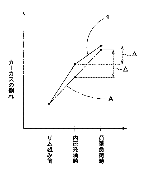
このような凹湾曲部21をビード外側面4Sbに設けることにより、前記凹湾曲部21を設けていない従来タイヤAに比して、内圧充填時におけるカーカス6のフランジ側への倒れが起こりやすくなる。他方、ビード外側面4Sbに凸湾曲部20を設けることにより、荷重負荷時におけるカーカス6のフランジ側への倒れを小さすることができる。即ち、図4に概念的に示すように、本実施形態のタイヤ1では、従来タイヤA(一点鎖線で示す)に比して、内圧充填時におけるカーカス6の倒れが大きくなる反面、内圧充填時から荷重負荷時に至る間の倒れ量Δを、逆に小さくすることができる。その結果、カーカス6のプライ折返し部6bの外端6Eにおける歪の繰り返し変化を低減でき、ビード耐久性を向上することが可能となる。
By providing such a concave
そのためには、前記最大厚さTmax と最小厚さTmin との差(Tmax −Tmin )が3〜9mmの範囲であることが好ましい。前記差(Tmax −Tmin )が3mm未満の場合、前記効果を十分に発揮発揮させることが難しくなる。逆に、前記差(Tmax −Tmin )が9mmを越えると、嵌合時に隙間が発生して、走行中にリムずれを起こしてしまうという不利を招く。従って、前記差(Tmax −Tmin )の下限値は4mm以上が好ましく、上限値は6mm以下が好ましい。 For this purpose, the difference (Tmax−Tmin) between the maximum thickness Tmax and the minimum thickness Tmin is preferably in the range of 3 to 9 mm. When the difference (Tmax−Tmin) is less than 3 mm, it is difficult to sufficiently exhibit the above effects. On the contrary, if the difference (Tmax−Tmin) exceeds 9 mm, a gap is generated at the time of fitting, causing a disadvantage that rim displacement occurs during running. Therefore, the lower limit of the difference (Tmax−Tmin) is preferably 4 mm or more, and the upper limit is preferably 6 mm or less.
又前記凹湾曲部21は、曲率半径r1が20〜50mmの円弧で形成されるのが好ましい。前記曲率半径r1が50mmを越える場合、内圧充填時におけるカーカス6の倒れが小さくなってしまい、内圧充填時から荷重負荷時に至る間の倒れ量を減少させることが難しくなる。逆に、前記曲率半径r1が20mm未満の場合、前記凹湾曲部21に応力が集中してしまい、この凹湾曲部21を起点とした新たな損傷(クラックなど。)を招く可能性が生じる。このような観点から、曲率半径r1の下限値は30mm以上が好ましく、又上限値は40mm以下が好ましい。
The concave
又前記凹湾曲部21と凸湾曲部20とは、S字状に滑らかに連なって形成されるのが好ましい。又前記凸湾曲部20は、前記フランジ接触領域Fに形成される。言い換えれば、前記凸湾曲部20は、硬質のチェーファゴム10によって形成される。又前記凸湾曲部20は、前記界面Kに滑らかには連なる。この凸湾曲部20も円弧で形成されるのが好ましく、その曲率半径r2は40〜70mmの範囲が好ましい。
Moreover, it is preferable that the concave
又前記最小厚さ点P2は、前記ビードコア5の半径方向内面5Sに沿ってのびるコア内面線Yよりも半径方向外側に位置することが好ましい。最小厚さ点P2がコア内面線Yの線上、或いはコア内面線Yよりも半径方向内側に位置する場合には、荷重負荷時におけるカーカス6のフランジ側への倒れを小さくすることが難しくなる。
The minimum thickness point P2 is preferably located on the radially outer side of the core inner surface line Y extending along the radial
又内圧充填時から荷重負荷時に至る間の倒れ量を小さくするために、前記チェーファゴム10を、デュロメータC硬さが70〜95の超硬質のゴムで形成するのも好ましい。しかしゴム硬さが95(デュロメータC硬さ)を越える場合、ゴムが硬質化してしまい、チェーファゴム10にゴム割れなどの損傷を招く傾向となる。又70(デュロメータC硬さ)未満の場合、ビード耐久性の向上効果が低下する傾向を招く。なお通常、チェーファゴム10のゴム硬さは通常、デュロメータA硬さで70〜85程度である。
It is also preferable to form the
以上、本発明の特に好ましい実施形態について詳述したが、本発明は図示の実施形態に限定されることなく、種々の態様に変形して実施しうる。 As mentioned above, although especially preferable embodiment of this invention was explained in full detail, this invention is not limited to embodiment of illustration, It can deform | transform and implement in a various aspect.
図1の構造をなす重荷重用ラジアルタイヤを表1の仕様で試作するとともに、各試供タイヤのビード耐久性をテストし比較した。表1に記載以外は、実質的に同仕様である。共通仕様は、以下のとおりである。
・タイヤサイズ :11R22.5
・タイヤ断面高さH :239.8mm
・リムサイズ:22.5×7.50、
・フランジ高さHf :12.7mm
・カーカス
プライ数 :1枚
コード材料 :スチール
コードの配列角度 :90度(対周方向)
プライ折返し部の高さH6 :37mm
・ベルト層
プライ数 :4枚
コード材料 :スチール
コードの配列角度 :右50度/右18度/左18度/左18度(対周方向)
(内側のプライから外側のプライの順であり、「右」は平面視右上がりを示し、「左」は平面視左上がりを示す)
・ビード補強コード層(U字状)
プライ数 :1枚
コード材料 :スチール
コードの配列角度 :25度(対周方向)
内片部の高さHi :27mm
外片部の高さHo :27mm
・ビードエーペックスゴム
高さH8 :80mm
内側のエーペックス部のゴム硬度(デュロメータA硬さ):80
外側のエーペックス部のゴム硬度(デュロメータA硬さ):40
A heavy-duty radial tire having the structure shown in FIG. 1 was prototyped according to the specifications shown in Table 1, and the bead durability of each sample tire was tested and compared. Except as described in Table 1, the specifications are substantially the same. The common specifications are as follows.
・ Tire size: 11R22.5
・ Tire cross-section height H: 239.8 mm
・ Rim size: 22.5 × 7.50,
・ Flange height Hf: 12.7mm
-Number of carcass plies: 1 piece Cord material: Steel Cord arrangement angle: 90 degrees (direction of circumference)
Ply turn-up height H6: 37 mm
Belt layer Number of plies: 4 Cord material: Steel Cord arrangement angle: Right 50 degrees / Right 18 degrees / Left 18 degrees / Left 18 degrees (direction of circumference)
(The order is from the inner ply to the outer ply. “Right” indicates a right-up in plan view, and “left” indicates a left-up in plan view.)
・ Bead reinforcement cord layer (U-shaped)
Number of plies: 1 Cord material: Steel Cord arrangement angle: 25 degrees (direction of circumference)
Inner piece height Hi: 27 mm
Outer piece height Ho: 27 mm
・ Bead apex rubber Height H8: 80mm
Inner apex rubber hardness (durometer A hardness): 80
Rubber hardness of outer apex part (durometer A hardness): 40
又、ビード外側面の凸湾曲部および凹湾曲部以外の輪郭形状J(図3に示す。)は、各タイヤとも実質的に同一である。又表中、δaは輪郭形状Jからの凸湾曲部の最大突出量、δbは凹湾曲部の最大凹み量を意味する。 Further, the contour shape J (shown in FIG. 3) other than the convex curved portion and the concave curved portion on the outer surface of the bead is substantially the same for each tire. In the table, δa means the maximum protrusion amount of the convex curved portion from the contour shape J, and δb means the maximum concave amount of the concave curved portion.
<ビード耐久性>
ドラム試験機を用い、各試供タイヤをリム(7.50×22.5)、内圧(800kPa)、荷重(88.26kN)の条件下にて、速度20km/hで走行させ、ビード部に損傷が発生するまでの走行距離を、比較例1を100とする指数で表記した。数値が大きいほどビード耐久性に優れている。又発生したビード損傷において、「A」はカーカスの折返し端にコードルースが発生したことを意味する。又「B」は、ビード部の外側面にゴム割(クラック)が発生したことを意味する。
<Bead durability>
Using a drum testing machine, each sample tire was run at a speed of 20 km / h under the conditions of a rim (7.50 × 22.5), internal pressure (800 kPa), and load (88.26 kN), and the bead portion was damaged. The distance traveled until the occurrence of the problem was expressed as an index with Comparative Example 1 taken as 100. The larger the value, the better the bead durability. In the bead damage that occurred, “A” means that a cord loose occurred at the folded end of the carcass. “B” means that a rubber crack (crack) occurred on the outer surface of the bead portion.
1 重荷重用ラジアルタイヤ
2 トレッド部
3 サイドウォール部
4 ビード部
4h ビードヒール点
4Sb 外側面
5 ビードコア
5S 半径方向内面
6 カーカス
6A カーカスプライ
6a プライ本体部
6b プライ折返し部
10 チェーファゴム
20 凸湾曲部
21 凹湾曲部
L 領域範囲
P1 最大厚さ点
P2 最小厚さ点
X コア最大巾線
Y コア内面線
DESCRIPTION OF SYMBOLS 1 Radial tire for
Claims (4)
ビードヒール点の位置から前記プライ折返し部の半径方向外端の位置に至る領域範囲において、
前記ビード部のタイヤ軸方向外側面に、タイヤ外側に凸状に湾曲しかつ前記プライ折返し部とビード部の外側面との間の厚さTが最大厚さTmax となる最大厚さ点を有する凸湾曲部と、凹状に湾曲しかつ前記厚さTが最小厚さT min となる最小厚さ点を有する凹湾曲部とを具え、
しかも前記厚さTが、前記最小厚さ点から最大厚さ点まで漸増し、かつ前記最大厚さ点からプライ折返し部の半径方向外端の位置まで漸減するとともに、
前記ビードコアは断面六角形状をなし、しかも前記最大厚さ点は、前記ビードコアの半径方向内面と平行かつ該ビードコアの最大巾位置を通るコア最大巾線よりも半径方向外側に位置し、かつ前記最小厚さ点は、前記コア最大巾線の線上又は前記コア最大巾線よりも半径方向内側に位置することを特徴とする重荷重用ラジアルタイヤ。 A steel carcass cord is used that has a ply turn-up part that is turned from the inside to the outside in the tire axial direction around the bead core on both sides of the ply body part extending from the tread part through the sidewall part to the bead core of the bead part. A heavy duty radial tire having a carcass made of a carcass ply and mounted on a 15 ° taper rim,
In the region range from the position of the bead heel point to the position of the radially outer end of the ply turn-up portion,
The outer surface in the tire axial direction of the bead portion has a maximum thickness point that is convexly convex toward the outer side of the tire and that the thickness T between the ply turn-up portion and the outer surface of the bead portion is the maximum thickness Tmax. A convex curved portion, and a concave curved portion that is concavely curved and has a minimum thickness point at which the thickness T is the minimum thickness T min,
Moreover, the thickness T gradually increases from the minimum thickness point to the maximum thickness point, and gradually decreases from the maximum thickness point to the position of the radially outer end of the ply turn-up portion,
The bead core has a hexagonal cross-section, and the maximum thickness point is located radially outward from a core maximum width line parallel to a radial inner surface of the bead core and passing through a maximum width position of the bead core, and the minimum The thickness point is located on the core maximum width line or radially inward of the core maximum width line, the heavy duty radial tire characterized by the above.
The bead portion includes a chafer rubber that is exposed to the outer surface in a flange contact area that contacts the flange of the 15 ° taper rim on the outside of the carcass, and the chafer rubber has a durometer C hardness of 70 to 95. The heavy duty radial tire according to any one of claims 1 to 3.
Priority Applications (1)
| Application Number | Priority Date | Filing Date | Title |
|---|---|---|---|
| JP2013067061A JP6110702B2 (en) | 2013-03-27 | 2013-03-27 | Heavy duty radial tire |
Applications Claiming Priority (1)
| Application Number | Priority Date | Filing Date | Title |
|---|---|---|---|
| JP2013067061A JP6110702B2 (en) | 2013-03-27 | 2013-03-27 | Heavy duty radial tire |
Publications (2)
| Publication Number | Publication Date |
|---|---|
| JP2014189178A true JP2014189178A (en) | 2014-10-06 |
| JP6110702B2 JP6110702B2 (en) | 2017-04-05 |
Family
ID=51835878
Family Applications (1)
| Application Number | Title | Priority Date | Filing Date |
|---|---|---|---|
| JP2013067061A Active JP6110702B2 (en) | 2013-03-27 | 2013-03-27 | Heavy duty radial tire |
Country Status (1)
| Country | Link |
|---|---|
| JP (1) | JP6110702B2 (en) |
Cited By (6)
| Publication number | Priority date | Publication date | Assignee | Title |
|---|---|---|---|---|
| JP2017043281A (en) * | 2015-08-28 | 2017-03-02 | 住友ゴム工業株式会社 | Pneumatic tire |
| US20170246920A1 (en) * | 2016-02-26 | 2017-08-31 | Apollo Tyres Global R&D B.V. | Vehicle tyre with enhanced bead contour |
| JP2018075942A (en) * | 2016-11-09 | 2018-05-17 | 住友ゴム工業株式会社 | Pneumatic tire |
| JP2019112038A (en) * | 2017-12-26 | 2019-07-11 | Toyo Tire株式会社 | Pneumatic tire |
| JP7131665B1 (en) | 2021-07-07 | 2022-09-06 | 住友ゴム工業株式会社 | Heavy duty tire |
| JP7131664B1 (en) | 2021-07-07 | 2022-09-06 | 住友ゴム工業株式会社 | Heavy duty tire |
Citations (5)
| Publication number | Priority date | Publication date | Assignee | Title |
|---|---|---|---|---|
| JPH01244903A (en) * | 1988-03-25 | 1989-09-29 | Yokohama Rubber Co Ltd:The | Radial tire |
| JPH06255324A (en) * | 1993-03-05 | 1994-09-13 | Bridgestone Corp | Pneumatic radial tire |
| JPH09263113A (en) * | 1995-11-29 | 1997-10-07 | Bridgestone Corp | 15× taper radial tire for truck and bus |
| JP2005186672A (en) * | 2003-12-24 | 2005-07-14 | Sumitomo Rubber Ind Ltd | Pneumatic tire |
| JP2007216883A (en) * | 2006-02-17 | 2007-08-30 | Sumitomo Rubber Ind Ltd | Pneumatic tire |
-
2013
- 2013-03-27 JP JP2013067061A patent/JP6110702B2/en active Active
Patent Citations (5)
| Publication number | Priority date | Publication date | Assignee | Title |
|---|---|---|---|---|
| JPH01244903A (en) * | 1988-03-25 | 1989-09-29 | Yokohama Rubber Co Ltd:The | Radial tire |
| JPH06255324A (en) * | 1993-03-05 | 1994-09-13 | Bridgestone Corp | Pneumatic radial tire |
| JPH09263113A (en) * | 1995-11-29 | 1997-10-07 | Bridgestone Corp | 15× taper radial tire for truck and bus |
| JP2005186672A (en) * | 2003-12-24 | 2005-07-14 | Sumitomo Rubber Ind Ltd | Pneumatic tire |
| JP2007216883A (en) * | 2006-02-17 | 2007-08-30 | Sumitomo Rubber Ind Ltd | Pneumatic tire |
Cited By (10)
| Publication number | Priority date | Publication date | Assignee | Title |
|---|---|---|---|---|
| JP2017043281A (en) * | 2015-08-28 | 2017-03-02 | 住友ゴム工業株式会社 | Pneumatic tire |
| US20170246920A1 (en) * | 2016-02-26 | 2017-08-31 | Apollo Tyres Global R&D B.V. | Vehicle tyre with enhanced bead contour |
| US10821784B2 (en) | 2016-02-26 | 2020-11-03 | Apollo Tyres Global R&D B.V. | Vehicle tyre with enhanced bead contour |
| JP2018075942A (en) * | 2016-11-09 | 2018-05-17 | 住友ゴム工業株式会社 | Pneumatic tire |
| JP2019112038A (en) * | 2017-12-26 | 2019-07-11 | Toyo Tire株式会社 | Pneumatic tire |
| JP7105064B2 (en) | 2017-12-26 | 2022-07-22 | Toyo Tire株式会社 | pneumatic tire |
| JP7131665B1 (en) | 2021-07-07 | 2022-09-06 | 住友ゴム工業株式会社 | Heavy duty tire |
| JP7131664B1 (en) | 2021-07-07 | 2022-09-06 | 住友ゴム工業株式会社 | Heavy duty tire |
| JP2023009352A (en) * | 2021-07-07 | 2023-01-20 | 住友ゴム工業株式会社 | Heavy-duty tire |
| JP2023009370A (en) * | 2021-07-07 | 2023-01-20 | 住友ゴム工業株式会社 | Heavy-duty tire |
Also Published As
| Publication number | Publication date |
|---|---|
| JP6110702B2 (en) | 2017-04-05 |
Similar Documents
| Publication | Publication Date | Title |
|---|---|---|
| JP6249518B2 (en) | Pneumatic tire | |
| JP5394415B2 (en) | Pneumatic radial tire | |
| JP6110702B2 (en) | Heavy duty radial tire | |
| JP5545898B2 (en) | Heavy duty pneumatic tire | |
| JP2724291B2 (en) | Heavy duty tire | |
| JP5759134B2 (en) | Pneumatic tire | |
| JPWO2011065006A1 (en) | Heavy duty pneumatic radial tire | |
| JP5297488B2 (en) | Pneumatic tire | |
| JP6209036B2 (en) | Pneumatic tire | |
| JP6389426B2 (en) | Pneumatic tire | |
| WO2013105309A1 (en) | Heavy duty pneumatic tire | |
| JP2017121888A (en) | Pneumatic tire | |
| JP6121285B2 (en) | Pneumatic tire | |
| JP3930474B2 (en) | Heavy duty tire | |
| JP2020069992A (en) | Pneumatic tire | |
| JP6162923B2 (en) | Heavy duty pneumatic radial tire | |
| JP6052762B2 (en) | Pneumatic tires for light trucks | |
| JP3890050B2 (en) | Heavy duty tire | |
| JP6555998B2 (en) | Pneumatic tire | |
| JP6450111B2 (en) | Pneumatic tire | |
| JP4628080B2 (en) | Heavy duty pneumatic radial tire | |
| JP2017137007A (en) | Pneumatic tire | |
| JP4703013B2 (en) | Pneumatic tire | |
| JP6989374B2 (en) | Pneumatic radial tires for heavy loads | |
| JP5519380B2 (en) | Heavy duty pneumatic radial tire |
Legal Events
| Date | Code | Title | Description |
|---|---|---|---|
| A621 | Written request for application examination |
Free format text: JAPANESE INTERMEDIATE CODE: A621 Effective date: 20151211 |
|
| A977 | Report on retrieval |
Free format text: JAPANESE INTERMEDIATE CODE: A971007 Effective date: 20160823 |
|
| A131 | Notification of reasons for refusal |
Free format text: JAPANESE INTERMEDIATE CODE: A131 Effective date: 20160830 |
|
| A521 | Request for written amendment filed |
Free format text: JAPANESE INTERMEDIATE CODE: A523 Effective date: 20161007 |
|
| TRDD | Decision of grant or rejection written | ||
| A01 | Written decision to grant a patent or to grant a registration (utility model) |
Free format text: JAPANESE INTERMEDIATE CODE: A01 Effective date: 20170228 |
|
| A61 | First payment of annual fees (during grant procedure) |
Free format text: JAPANESE INTERMEDIATE CODE: A61 Effective date: 20170310 |
|
| R150 | Certificate of patent or registration of utility model |
Ref document number: 6110702 Country of ref document: JP Free format text: JAPANESE INTERMEDIATE CODE: R150 |
|
| R250 | Receipt of annual fees |
Free format text: JAPANESE INTERMEDIATE CODE: R250 |
|
| R250 | Receipt of annual fees |
Free format text: JAPANESE INTERMEDIATE CODE: R250 |
|
| R250 | Receipt of annual fees |
Free format text: JAPANESE INTERMEDIATE CODE: R250 |
|
| R250 | Receipt of annual fees |
Free format text: JAPANESE INTERMEDIATE CODE: R250 |
|
| R250 | Receipt of annual fees |
Free format text: JAPANESE INTERMEDIATE CODE: R250 |