JP2014189145A - Dropping device and dropping method of space structure for revolving around the earth to the earth - Google Patents
Dropping device and dropping method of space structure for revolving around the earth to the earth Download PDFInfo
- Publication number
- JP2014189145A JP2014189145A JP2013066375A JP2013066375A JP2014189145A JP 2014189145 A JP2014189145 A JP 2014189145A JP 2013066375 A JP2013066375 A JP 2013066375A JP 2013066375 A JP2013066375 A JP 2013066375A JP 2014189145 A JP2014189145 A JP 2014189145A
- Authority
- JP
- Japan
- Prior art keywords
- earth
- thin film
- space structure
- space
- escape
- Prior art date
- Legal status (The legal status is an assumption and is not a legal conclusion. Google has not performed a legal analysis and makes no representation as to the accuracy of the status listed.)
- Granted
Links
- 238000000034 method Methods 0.000 title claims abstract description 16
- 239000010409 thin film Substances 0.000 claims abstract description 99
- 238000003860 storage Methods 0.000 claims abstract description 46
- 230000002265 prevention Effects 0.000 claims description 23
- 210000000078 claw Anatomy 0.000 claims description 22
- 238000005520 cutting process Methods 0.000 claims description 6
- 238000003825 pressing Methods 0.000 claims description 5
- 230000002093 peripheral effect Effects 0.000 claims description 4
- 239000007789 gas Substances 0.000 description 15
- 239000000463 material Substances 0.000 description 12
- 238000010438 heat treatment Methods 0.000 description 8
- 230000008878 coupling Effects 0.000 description 2
- 238000010168 coupling process Methods 0.000 description 2
- 238000005859 coupling reaction Methods 0.000 description 2
- 230000007423 decrease Effects 0.000 description 2
- 230000005484 gravity Effects 0.000 description 2
- YMHOBZXQZVXHBM-UHFFFAOYSA-N 2,5-dimethoxy-4-bromophenethylamine Chemical compound COC1=CC(CCN)=C(OC)C=C1Br YMHOBZXQZVXHBM-UHFFFAOYSA-N 0.000 description 1
- 206010037660 Pyrexia Diseases 0.000 description 1
- 229910000831 Steel Inorganic materials 0.000 description 1
- 239000004699 Ultra-high molecular weight polyethylene Substances 0.000 description 1
- 241000545067 Venus Species 0.000 description 1
- 230000003213 activating effect Effects 0.000 description 1
- QVGXLLKOCUKJST-UHFFFAOYSA-N atomic oxygen Chemical compound [O] QVGXLLKOCUKJST-UHFFFAOYSA-N 0.000 description 1
- 238000000151 deposition Methods 0.000 description 1
- 230000000694 effects Effects 0.000 description 1
- 239000010408 film Substances 0.000 description 1
- 239000000446 fuel Substances 0.000 description 1
- 230000020169 heat generation Effects 0.000 description 1
- 238000005259 measurement Methods 0.000 description 1
- 239000001301 oxygen Substances 0.000 description 1
- 229910052760 oxygen Inorganic materials 0.000 description 1
- 229920001721 polyimide Polymers 0.000 description 1
- 230000003449 preventive effect Effects 0.000 description 1
- 239000010959 steel Substances 0.000 description 1
- 239000000126 substance Substances 0.000 description 1
- 229920000785 ultra high molecular weight polyethylene Polymers 0.000 description 1
- 239000002699 waste material Substances 0.000 description 1
- 238000004804 winding Methods 0.000 description 1
Images


Abstract
Description
本発明は、地球上空の宇宙空間の軌道上を周回する宇宙構造物を所望の時期に地球へ向って落下させるための宇宙構造物の地球への落下装置及び落下方法に関するものである。 The present invention relates to an apparatus and a method for dropping a space structure on the earth for dropping a space structure that circulates in an orbit of outer space over the earth toward the earth at a desired time.
地球から宇宙へ打ち上げられて、地球上空の宇宙空間の軌道を周回する人工衛星等の宇宙構造物(以下、単に「衛星」とも称する)は、そのミッションが終了した後も地球を周回し続ける。このため、地球上空の宇宙空間を周回するミッション終了済みの衛星の数は年々増加しており、将来的には宇宙空間のゴミとして他の衛星の宇宙利用を妨げる虞れがある。しかしながら、ミッションが終了した衛星を地球へ落下させて消滅させる技術は未だ確立されておらず、将来的には上記虞れが益々増大することが予想される。 Space structures such as artificial satellites (hereinafter also simply referred to as “satellite”) that are launched from the earth into space and orbit in the outer space of the earth continue to orbit the earth after the mission ends. For this reason, the number of satellites that have completed missions orbiting outer space over the earth has been increasing year by year, and in the future there is a risk of hindering the use of other satellites as space waste. However, a technique for dropping a satellite that has completed a mission to the earth and extinguishing it has not yet been established, and it is expected that the above-mentioned fear will increase in the future.
そこで本発明は、ミッションが終了した衛星を速やかに地球へ落下させて消滅させることができる宇宙構造物の地球への落下装置及び落下方法を提供することを目的とする。 Accordingly, an object of the present invention is to provide an apparatus and method for dropping a space structure onto the earth that can quickly drop a satellite that has completed a mission to the earth and extinguish it.
より詳しくは、次のとおりである。衛星の打ち上げロケットには大量の燃料を要するので、衛星は極力小型軽量化する必要があり、衛星に装備される地球への落下装置も当然に小型軽量化する必要がある。そこで本発明は、より小型軽量化できる地球を周回する宇宙構造物の地球への落下装置及び落下方法を実現することを目的とする。 More details are as follows. Since a satellite launch vehicle requires a large amount of fuel, it is necessary to reduce the size and weight of the satellite as much as possible, and it is natural to reduce the size and weight of the earth drop device installed in the satellite. Accordingly, an object of the present invention is to realize an apparatus and a method for dropping a space structure orbiting the earth that can be reduced in size and weight.
また地球への落下装置は、衛星打ち上げ後、相当の長年月が経過したミッション終了後に作動させて衛星を地球へ向って落下させるものであるから、打ち上げ後、長年月が経った場合でも確実に作動させることができる高い信頼性が要求される。そこで本発明は、このような高い信頼性を確保できる地球を周回する宇宙構造物の地球への落下装置及び落下方法を実現することを目的とする。 In addition, since the device for falling to the earth is operated after the mission has been completed for a long time after launching the satellite, the satellite is dropped toward the earth, so even if many years have passed since the launch. High reliability that can be operated is required. Therefore, an object of the present invention is to realize an apparatus and a method for dropping a space structure orbiting the earth that can ensure such high reliability.
請求項1に記載の地球を周回する宇宙構造物の地球への落下装置は、縮小された薄膜と、薄膜を展開する展開手段を備え、指令部からの指令によって展開手段を作動させて薄膜を宇宙空間に拡げて展開させることを特徴とするものである。 An apparatus for dropping a space structure that orbits the earth according to claim 1 includes a reduced thin film and a deployment means for deploying the thin film, and operates the deployment means in response to a command from the commanding unit. It is characterized by being expanded and expanded in outer space.
請求項2に記載の地球を周回する宇宙構造物の地球への落下装置は、望ましくは前記展開手段がコンベックステープである。
Preferably, in the apparatus for dropping a space structure orbiting the earth to the earth according to
請求項3に記載の地球を周回する宇宙構造物の地球への落下方法は、宇宙構造物を落下させる時期が到来したならば、指令部からの指令により薄膜を宇宙空間に拡げて展開させ、薄膜が受ける宇宙空間に薄く存在する気体の気体抵抗によって宇宙構造物の地球周回速度を次第に低下させて宇宙構造物を地球へ向って落下させ、大気との摩擦熱によって宇宙構造物を燃尽・消滅させることを特徴とするものである。
In the method of dropping a space structure that orbits the earth according to
請求項4に記載の地球を周回する宇宙構造物の地球への落下装置は、宇宙構造物に備えられる収納部と、収納部の内部に設けられた中心軸と、それぞれの先端部同士が互いに結合され、且つ中心軸に巻回されて収納部の内部に縮小して収納される薄膜及びコンベックステープと、薄膜及びコンベックステープを収納部から脱出させる脱出手段とを備え、収納部はコンベックステープが自身のバネ力によって伸長するのを防止する伸長防止手段を兼務しており、指令部からの指令により薄膜及びコンベックステープを脱出手段により収納部から脱出させてコンベックステープが自身のバネ力によって伸長することにより、薄膜を宇宙空間に拡げて展開させることを特徴とするものである。 According to a fourth aspect of the present invention, there is provided a device for dropping a space structure that circulates the earth onto the earth, a storage unit provided in the space structure, a central axis provided in the storage unit, and respective tip portions thereof are mutually connected. A thin film and a convex tape which are coupled and wound around a central axis and are stored in a reduced size inside the storage unit; and an escape means for allowing the thin film and the convex tape to escape from the storage unit. It also serves as an extension preventing means that prevents it from extending due to its own spring force, and the convex tape is extended by its own spring force by causing the thin film and the convex tape to escape from the storage portion by means of the escape means in response to a command from the command section. Thus, the thin film is expanded and expanded in outer space.
請求項5に記載の地球を周回する宇宙構造物の地球への落下装置は、望ましくは前記脱出手段が、前記薄膜と前記コンベックステープを前記収納部から脱出する方向に移動するように付勢する付勢手段であることを特徴とするものである。 Preferably, in the apparatus for dropping an earth structure around the earth to the earth according to claim 5, the escape means preferably urges the thin film and the convex tape to move in a direction to escape from the storage portion. It is an urging means.
請求項6に記載の地球を周回する宇宙構造物の地球への落下装置は、宇宙構造物に備えられる収納部と、収納部の内部に設けられた中心軸と、それぞれの先端部同士が互いに結合され、且つ中心軸に巻回されて収納部の内部に縮小して収納される薄膜及びコンベックステープと、薄膜とコンベックステープが収納部から脱出する方向に移動するように付勢する付勢手段から成る脱出手段と、付勢手段の付勢力に抗して薄膜及びコンベックステープが収納部から脱出するのを防止する脱出防止手段と、脱出防止手段による脱出防止状態を解除する解除手段とを備え、収納部はコンベックステープが自身のバネ力によって伸長するのを防止する伸長防止手段を兼務しており、指令部からの指令によって解除手段を作動させて脱出防止状態を解除することにより、薄膜及びコンベックステープを付勢手段の付勢力により収納部から脱出させて、コンベックステープの伸長しようとするバネ力により薄膜を宇宙空間に展開させることを特徴とするものである。 According to a sixth aspect of the present invention, there is provided a device for dropping a space structure that circulates the earth onto the earth, a storage unit provided in the space structure, a central axis provided inside the storage unit, and respective tip portions of each other. A thin film and a convex tape which are coupled and wound around a central axis and are stored in a reduced size inside the storage portion, and a biasing means for biasing the thin film and the convex tape so as to move in a direction to escape from the storage portion. An escape means for preventing the thin film and the convex tape from escaping from the storage portion against the urging force of the urging means, and a release means for releasing the escape prevention state by the escape prevention means. The storage part also serves as an extension preventing means for preventing the convex tape from extending due to its own spring force, and the release means is operated by a command from the command part to release the escape prevention state. It allows the thin film and convex tape by escape from the housing portion by the urging force of the urging means, is characterized in that deploying the thin film in space by a spring force to be extended in the convex tape.
請求項7に記載の地球を周回する宇宙構造物の地球への落下装置は、望ましくは前記脱出防止手段が、薄膜及びコンベックステープを上方から押えつけるカバー部材と、カバー部材が前記付勢手段の付勢力により薄膜及びコンベックステープが脱出方向へ移動するのを防止する移動防止手段から成る。 Preferably, in the apparatus for dropping the earth structure orbiting the earth according to claim 7, the escape prevention means preferably includes a cover member for pressing the thin film and the convex tape from above, and a cover member for the biasing means. It comprises movement preventing means for preventing the thin film and the convex tape from moving in the escape direction due to the urging force.
請求項8に記載の地球を周回する宇宙構造物の地球への落下装置は、望ましくは前記移動防止手段が、前記カバー部材に設けられたひもと複数のチャック体であって、ひもでチャック体をしばり付けることにより、前記中心軸の上端部をチャック体によりチャックして前記中心軸が前記付勢手段により前記脱出する方向へ移動するのを防止するものであり、また前記解除手段がひもの切断手段である。 The apparatus for dropping a space structure that circulates around the earth according to claim 8 is preferably configured such that the movement preventing means is a plurality of chuck bodies and a plurality of chuck bodies provided on the cover member. The upper end of the central shaft is chucked by a chuck body to prevent the central shaft from moving in the direction of escape by the biasing means, and the release means is a string. Cutting means.
請求項9に記載の地球を周回する宇宙構造物の地球への落下装置は、宇宙構造物に備えられる収納部と、収納部の内部に設けられた中心軸と、収納部の内部にあって中心軸に回転自在に装着された回転体と、回転体の先端の係止部に係合して回転体が収納部の内部において回転するのを阻止するストッパと、それぞれの先端部同士が互いに結合されて回転体を間に挟さんで中心軸に巻回されて縮小された薄膜及びコンベックステープと、収納部の内部にあって上から順に積層された薄膜と回転体とコンベックステープが収納部から脱出する方向に付勢する付勢手段から成る脱出手段と、付勢手段の付勢力により薄膜とコンベックステープが収納部から脱出するのを防止する脱出防止手段と、指令部からの指令によって脱出防止手段を作動させて脱出防止状態を解除し、付勢手段の付勢力により薄膜とコンベックステープを収納部の外へ脱出させてコンベックステープがまっすぐ伸長しようとする自身のバネ力により薄膜を宇宙空間に拡げて展開させる脱出防止状態の解除手段とを備えたことを特徴とするものである。 The apparatus for dropping a space structure that circulates around the earth according to claim 9 is provided in a storage unit provided in the space structure, a central axis provided in the storage unit, and in the storage unit. A rotating body that is rotatably mounted on the central axis, a stopper that engages with a locking portion at the front end of the rotating body and prevents the rotating body from rotating inside the storage unit, and the respective front ends are mutually connected. A thin film and a convex tape which are combined and are wound around a central axis with a rotating body interposed therebetween and reduced, and a thin film, a rotating body and a convex tape which are stacked in order from the top inside the storage section Evacuation means comprising urging means for urging in the direction of escaping, escaping prevention means for preventing the thin film and the convex tape from escaping from the storage portion by the urging force of the urging means, and evacuation according to instructions from the command section Activating the prevention means Escape that releases the escape prevention state and causes the thin film and the convex tape to escape out of the storage part by the biasing force of the biasing means, and the convex tape expands straight into outer space by its own spring force that tries to stretch straight. And a preventive state releasing means.
請求項10に記載の地球を周回する宇宙構造物の地球への落下装置は、望ましくは前記回転体が爪車であり、また前記係止部が前記爪車の外周縁に設けられた爪部である。
The apparatus for dropping an earth structure around the earth according to
請求項11に記載の地球を周回する宇宙構造物の地球への落下装置は、望ましくは前記脱出防止手段が、中心軸に巻回された薄膜とコンベックステープを押さえつけるカバー部材と、カバー部材に設けられて前記中心軸の上端部をチャックする複数のチャック体と、チャック体による前記中心軸の上端部のチャック状態を保持するようにチャック体をしばり付けるひもから成り、また前記脱出防止状態の解除手段がひもの切断手段である。
The apparatus for dropping an earth structure around the earth according to
請求項12記載の地球を周回する宇宙構造物の地球への落下装置は、望ましくは前記コンベックステープは、一固定箇所につき複数枚重ねて固定されることを特徴とする請求項4〜11のいずれかに記載の地球を周回する宇宙構造物の地球への落下装置。
12. The apparatus for dropping a space structure orbiting the earth according to
請求項13に記載の地球を周回する宇宙構造物の地球への落下方法は、請求項4〜12の何れかに記載の地球を周回する宇宙構造物の地球への落下装置による地球を周回する宇宙構造物の地球への落下方法であって、宇宙構造物を落下させる時期が到来したならば、指令部からの指令により薄膜とコンベックステープを収納部から脱出手段により脱出させて、コンベックステープが自身のバネ力によって伸長することにより薄膜を宇宙空間に拡げて展開させ、薄膜が受ける宇宙空間に薄く存在する気体の気体抵抗によって宇宙構造物の地球周回速度を次第に低下させて宇宙構造物を地球へ向って落下させ、大気との摩擦熱によって宇宙構造物を燃尽・消滅させることを特徴とするものである。 The space structure orbiting the earth structure orbiting the earth according to claim 13 orbits the earth by the apparatus for dropping the space structure orbiting the earth according to any one of claims 4 to 12. When it is time to drop the space structure onto the earth, the thin film and the convex tape are escaped from the storage portion by the escape means according to the command from the command section. The thin film expands and expands in outer space by stretching by its own spring force, and the earth structure's orbital velocity is gradually reduced by the gas resistance of the gas that exists thinly in the outer space that the thin film receives. The space structure is burned down and extinguished by frictional heat with the atmosphere.
本発明によれば、衛星のミッションが終了し、所望の時期が到来したならば、指令部からの指令により、縮小されていた薄膜を展開手段により宇宙空間に広く展開し、展開した薄膜が宇宙空間にごく薄く存在する気体の気体抵抗を受けることにより衛星の地球周回速度を次第に低下させて早期に衛星を地球へ向って落下させることができる。しかも本発明によれば重量のあるモータ等のアクチュエータを不要にすることが可能であって、小型軽量で信頼性の高い地球を周回する宇宙構造物の地球への落下装置及び落下方法を実現できる。 According to the present invention, when the mission of the satellite is completed and a desired time has arrived, the thin film that has been reduced is widely deployed in outer space by the deploying means according to the command from the command unit, and the deployed thin film is By receiving the gas resistance of the gas that exists very thinly in space, the earth's orbiting speed of the satellite is gradually reduced, and the satellite can be dropped toward the earth at an early stage. Moreover, according to the present invention, it is possible to eliminate the need for a heavy actuator such as a motor, and it is possible to realize a device and method for dropping a space structure that circulates around the earth in a compact, lightweight and highly reliable manner. .
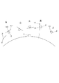
以下、図面を参照して本発明の実施の形態について説明する。図1において、地球1の上空の宇宙空間の軌道上には衛星2が周回している。衛星の地球周回速度は、例えば7.9km/秒程度である。衛星2は地球1から数百km程度上空の宇宙空間を周回しているが、この数百km程度上空の宇宙空間には僅かであるがごく薄い気体が存在している。本発明は、宇宙空間におけるこの僅かな気体の存在に着眼してなしたものである。なお、ここで言う宇宙空間に薄く存在する気体とは、宇宙空間に気体分子、原子等の状態で僅かに存在する物質を意味し、これらによる衛星の運動方向に反して作用する抗力を気体抵抗と称することとする。
Embodiments of the present invention will be described below with reference to the drawings. In FIG. 1, a
衛星2には、落下装置10が装備されている。後述するように、落下装置10には小さく折りたたんで中心軸の周りに巻回することにより縮小された薄膜11やコンベックステープ等が収納されており、薄膜11は地球上の指令部3から発信される指令により宇宙空間に拡がって展開する。衛星2は、図1のAに示す状態(薄膜が縮小されて収納部に収納された状態)で地球1の上空の軌道を周回して気象観測や地理測定などのミッションを実行しているが、ミッションが終了して衛星2が不要になると、図1のBに示すように、上記指令により薄膜11は宇宙空間に瞬時に拡がって展開する。薄膜11の展開状態での形状や大きさは任意に決定できるが、例えばタテヨコ共に2m、面積4m2程度の角形である。以下では薄膜が正方形の場合を例に取り上げ、機構の詳細を説明する。
The
薄膜11が展開した衛星2は、図1のB〜Eに示すように様々な姿勢に変動しながら軌道を周回するが、上記のように衛星が飛行する宇宙空間には僅かながらごく薄い気体が存在する。このため、航行中の薄膜11は僅かながらも気体抵抗を受けて徐々に衛星2の周回速度は低下し、ついには重力によって地球へ向って早期に下降を始め(矢印Z参照)、大気圏突入時に大気との摩擦熱により燃尽・消滅する。これにより衛星2は宇宙空間から除去される。
As shown in FIGS. 1B to 1E, the
薄膜11が宇宙空間に展開してから地球へ向って落下して燃尽するまでの期間は、衛星の質量、高度、薄膜の大きさ等によって相違するが、例えば100日間〜数十年程度である。薄膜は公知である(S.Nasir Adeliの論文「Deployment System for the CubeSail nano−Solar Sail Mission」。「Small Satellite Conference 2010,Logan,Utah,USA,210」に掲載)。
The period from when the
ただし、この論文に係る薄膜はSolar Sailシステムに係るものであって、地球から金星などの他の天体へ向って飛行する宇宙構造物において、展開された薄膜が背後から受ける太陽光の光圧によって航行速度を加速させるためのものである。これに対し、本発明の薄膜は、後に詳述するように、衛星の地球周回速度を減速させるためのものであり、その趣旨・目的、効果はこの論文のものとはまったく相違している。薄膜の素材としては、例えばポリイミドフィルムの両面をアルミ蒸着したものが、対原子状酸素耐性および対紫外線耐性を確保できるので望ましい。 However, the thin film according to this paper is related to the Solar Sail system, and in the space structure that flies from the earth to other celestial bodies such as Venus, the developed thin film depends on the light pressure of sunlight received from behind. It is for accelerating the navigation speed. In contrast, the thin film of the present invention, as will be described in detail later, is for reducing the earth's orbiting speed of the satellite, and its gist, purpose, and effect are completely different from those of this paper. As the material for the thin film, for example, a film obtained by vapor-depositing both sides of a polyimide film is desirable because it can secure resistance to oxygen at atoms and resistance to ultraviolet rays.
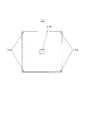
次に、落下装置10の詳細を説明する。図2は、衛星2とこれに搭載された落下装置10の外観を示すものである。図2に示すように、落下装置10は衛星2の適所(本例では一面)に装着されており、その内部に縮小して収納された薄膜(後述)は、指令部3(図1参照)から発信される指令によって瞬間的に宇宙空間に大きく拡がって展開する。図3は薄膜11の展開状態の平面図である。その4つの角部にはコンベックステープ(後述)の先端部と結合するための小孔11aが開孔されている。またその中央には中心軸(後述)を挿入するための開孔部11bが形成されている。
Next, details of the dropping
図2において、落下装置10は、半円板状の2個のチャック体12を有する。チャック体12は、2つ割りされた円板状のカバー部材31上に設けられている。チャック体は、2個に限らず、複数個でもよい。2個のチャック体12は、ひも13により互いに抱き合うように強くしばり付けられて接合され、両者一体で円板状体になっている。ひも13はチャック体12を一周周回して強く巻き付けられており、その両端部は衛星2に設けられた止部であるピン14に結合されている。ひも13の素材としては、例えば耐高張力性の超高分子量ポリエチレンが適用できる。
In FIG. 2, the dropping
2個の接合状態のチャック体12は、ひも13で強くしばり付けられることにより、図6に示すように収納部である有底円筒状のケース20の内部に設けられた中心軸21の上端部をチャックする。図2に示すように、ひも13には電熱線15が接触して配線されている。後述するように、指令部3からの指令によって電熱線15に電流が流れると、その発熱によってひも13は切断され、チャック体12はひも13のしばりによるチャック状態が解除されて互いに離れる方向である側方へスライドして離間し(図7の矢印L)、図7に示すように中心軸21の上端部のチャック体12によるチャック(ロック)状態は解除されて薄膜11は瞬間的に宇宙空間に拡がって展開する。
The two bonded
図4〜図6において、ケース20の内部の底面中央には中心軸21が立設されている。中心軸21の下端部は、ケース20の底面に装着されている。回転体としての爪車22は、取付筒26を介して中心軸21に回転自在に装着されている。図5に示すように、爪車22の先端の外周縁に多数(複数)形成された係止部としての爪部22aは、ケース20の内面に棒状に立設されたストッパ23(図4も参照)に係止され、その矢印M方向への水平回転が阻止されている。ストッパ23は、爪車22がケース20の内部から外部へ脱出する方向(図4、図6、図7では上方)へスライドして移動(上動)するときのスライドガイドを兼務している。なお、落下装置10は、ケース20上にあってチャック体12やカバー部材31を覆う蓋部材(不図示)を備えており、この蓋部材によりチャック体12を上から抑えている。
4 to 6, a
図4に示すように、爪車22の下面側には複数個(本実施の形態では4個を90度の位相で4か所に1個ずつ)のコンベックステープ25が取付筒26と円板状のコンベックステープガイド27に挟まれる形で巻回して縮小して収納されている。コンベックステープ25の基端部は取付筒26に固定されている。取付筒26には中心軸21に挿入される。また爪車22の上面側には、取付筒26が嵌入される嵌合体28が設けられており、これによりコンベックステープ伸展の際に、取付筒26、爪車22及び嵌合体28は一体となって回転自在となっている。一方、コンベックステープガイド27はケース20に固定されており(すなわち、コンベックステープガイド27はケース20に対して相対的に回転しないようになっており)、これによりコンベックステープ25の伸展方向を所定の向きに制御することが可能となっている。
As shown in FIG. 4, a plurality of convex tapes 25 (four in this embodiment, one in four at a phase of 90 degrees) are attached to the lower surface side of the
コンベックステープ25は、鋼板などの強いバネ性を有するテープ状の薄くて細長い長板体であり、巻尺等として広く用いられている公知のものである。巻回して縮小されたコンベックステープ25は、まっすぐになるように伸長しようとする強いバネ力を有している。コンベックステープ25は、必要であれば一か所につき複数個重ねて実装してもよいものであり、このようにすれば各コンベックステープ単体の変形の自由度を維持しつつ、より高い伸展強度の確保が可能となる。
The
図4において、爪車22の上面には、薄膜11がテープ状に折りたたまれて縮小して巻回されている。図3に示されるような角形の薄膜11を、図4に示すようにテープ状に折りたたんで巻回する方法の説明は省略する。コンベックステープ25と薄膜11は、爪車22をはさんで上下に積層して配設されている。このように上段の薄膜11と下段のコンベックステープ25を爪車22を間に挟んで積層し、中心軸21の周りに巻回してケース20に収納することにより、図4及び図6に示すように薄膜11とコンベックステープ25を小さく縮小した小型コンパクトな形状で収納でき、これにより落下装置10を小型コンパクト化できる。
In FIG. 4, the
4個のコンベックステープ25の先端部と角形の薄膜11の先端角部にはそれぞれ小孔25a、11aが形成されており(図3、図4を参照)、小孔25aと小孔11aは結合部としての細ひも29により一体的に結合されている(図6を参照)。なお、図4では細ひも29は省略している。薄膜11は嵌合体28に、またコンベックステープ25は取付筒26に巻回し、縮小状態でケース20に収納するので、収納部であるケース20は巻回されたコンベックステープ25が自身の強いバネ力によりまっすぐ直線状に伸長するのを防止する伸長防止手段を兼務している。
図5において、4本の細ひも29は爪車22の爪部22aのテーパ面に接する。後述するように、爪車22がケース20外に脱出してストッパ23によるその回転阻止状態(ロック状態)が解除されると、爪車22は矢印M方向に回転可能となるが、細ひも29はこの回転を邪魔しない柔軟性を有している。
In FIG. 5, the four
図6は薄膜11とコンベックステープ25が爪車22を上下から挟んで積層し、中心軸21の周りに巻回されて縮小してケース20に収納された状態を示している。また図7は、薄膜11とコンベックステープ25がケース20から脱出して宇宙空間に展開した状態を示している。図5、図6において、ケース20の内部には付勢手段としてのコイルバネから成るバネ材30が等間隔で複数個(本実施の形態では4個)設けられている。図6に示すように、薄膜11上には押え部材として上述したカバー部材31が設けられている。カバー部材31は付勢手段としてのコイルバネから成るバネ材30を圧縮状態で強く押さえつけ、上述したようにひも13はこの圧縮状態(中心軸21の上端部をしっかりチャックする状態)を保持するように2個のチャック体12を互いにしっかり接合させて互いに離間しないようにしっかりしばり付けてロックしている。
FIG. 6 shows a state in which the
図8(a)(b)において、中心軸21の上端には首細部21aが形成されている。首細部21aの上端と下端はテーパ面bとなっており、チャック体12の前面に形成されたテーパ面aが接合している。ひも13のしばりによる2個のチャック体12の接合状態(チャック状態、ロック状態)が解除されると、バネ材30のバネ力F1によりカバー部材31は上昇し(このとき薄膜11、爪車22、コンベックステープ25もカバー部材31と一体的に上昇する)、テーパ面bからテーパ面aが受ける側方への力F2により、2個のチャック体12は側方(中心軸21の上端部のチャック(ロック)状態を解除する方向。すなわち2個のチャック体12が互いに離れる方向であって、図8(b)の矢印Lで示す方向)へスライドして移動する。
8A and 8B, a
以上のように、図8(a)は、2個のチャック体12がひも13により強くしばり付けられて互いに接合した状態(中心軸21の上端部をロックした状態)を示している。また図8(b)は、ひも13が切断されてチャック体12による中心軸21の上端部のチャック(ロック)状態が解除され、バネ材30のバネ力F1によりカバー部材31が上昇した状態を示している。図9(a)において、電熱線15は、スイッチ部38を介して衛星2に設けられたスイッチ部38、バッテリー39、制御部40に接続されている。
As described above, FIG. 8A shows a state in which the two
地球上の宇宙基地の指令部3からロック状態解除の指令、すなわち衛星2の地球への落下指令が発信されると、スイッチ部38はONとなってひも13の切断手段である電熱線15に電流が流れ、その電熱によりひも13は切断され、ひも13によるチャック体12のしばり付け状態(チャック状態・ロック状態)が解除される。するとカバー部材31は図5、図8(a)に示す押え付け状態からバネ材30が伸長するバネ力F1によりケース20から脱出する方向(図6、図7では上方)へ瞬時に上昇する。したがって電熱線15は、指令部3(図1)からの指令によって電流が流れて作動することにより、チャック状態(薄膜11、爪車22、コンベックステープ25がケース20から脱出するのを防止する脱出防止状態)を解除する解除手段となっている。
When a command to release the locked state, that is, a command to drop the
ひも13によるチャック体12のしばり付け状態(チャック状態・ロック状態)が解除されると、カバー部材31はバネ材30が伸長するバネ力F1により瞬時に上昇し、図8(b)及び図9(b)に示すように、2個のチャック体12の前面のテーパ面aが首細部21aのテーパ面bから受ける拡開方向の上記力F2により互いに離間する方向へ移動する(図7、図8(b)、図9(b)の矢印L参照)。これにより薄膜11、爪車22、コンベックステープ25、カバー部材31はバネ材30のバネ力F1により一体的に瞬時に上昇し、図7に示すようにケース20内からケース20外へ飛び出して脱出すると同時に、ケース20内に閉じ込められていた状態から脱したコンベックステープ25は、自身の強いバネ力により瞬時にまっすぐな直線状になるよう伸長する。
When the clamping state (chucked state / locked state) of the
するとその角部の小孔11aがコンベックステープ25の先端部の小孔25aと細ひも29により結合された薄膜11は展開し、図1の位置Bに示すように宇宙空間大きく拡がる。したがって、下段のコンベックステープ25は、上段の薄膜11がケース20から脱出した直後にケース20外に脱出して薄膜11を展開させる展開手段になっている。
As a result, the
このようにして薄膜11が展開したならば、宇宙空間に存在する僅かなごく薄い気体の気体抵抗によって衛星2の地球周回速度は次第に低下し、ついには重力により次第に地上へ向って落下し、大気圏突入時に大気との摩擦熱により燃尽、消滅することは、図1を参照して説明したとおりである。
If the
以上の説明から明らかなように、チャック体12とこれをしばり付けるひも13から成るロック手段は、薄膜11やコンベックステープ25が一体化されたカバー部材31が、バネ材30のバネ力F1により上方(ケース20から脱出する方向)へ移動するのを防止する移動防止手段となっている。また薄膜11とコンベックステープ25を上方から押さえつけるカバー部材31と上記移動防止手段は、バネ材30のバネ力F1に抗して薄膜11及びコンベックステープ25がケース20の内部からケース20の外部へ脱出するのを防止する脱出防止手段となっている。また電熱線15は、指令部3から発信される指令によって脱出防止状態を解除する解除手段となっている。
As will be apparent from the above description, the lock means comprising the
本発明は、要は、地球を周回する衛星のミッションが終了して地球へ落下させるべき時期が到来したならば、縮小された薄膜を宇宙空間に広く展開させることにある。そして、この展開手段として、望ましくはコンベックステープを用いることにある。したがって本発明は上述した一実施の形態に限定されるものではなく、発明の趣旨から逸脱しない範囲内で様々な設計変更が可能である。例えば、薄膜の展開状態での寸法、平面形状、コンベックステープの個数、コンベックステープの固定箇所の個数等は任意に決定できる。また図10に示すように、コンベックステープ25は、一固定箇所につき必要展開力に応じて複数個(本例では2枚)重ねて、その基端部を取付筒26に固定してもよい。固定方法としては、ビス37が適用できる。図4に示すコンベックステープ25も、これと同様にビス37により取付筒26に固定される。
The main point of the present invention is to spread a reduced thin film widely in space when the mission of a satellite orbiting the earth is completed and it is time to drop it onto the earth. And as this expansion | deployment means, it exists in using a convex tape desirably. Therefore, the present invention is not limited to the above-described embodiment, and various design changes can be made without departing from the spirit of the invention. For example, the dimension in the developed state of the thin film, the planar shape, the number of convex tapes, the number of fixing points of the convex tapes, etc. can be arbitrarily determined. Further, as shown in FIG. 10, a plurality of convex tapes 25 (two in this example) may be stacked in accordance with a required deployment force per fixed portion, and the base end portion may be fixed to the mounting
またひも13は、電熱線15によらずに、抵抗素子のように電気的に発熱して高温になる要素や、電磁石によって突没するカッター等によっても切断することができる。また薄膜やコンベックステープの先端に設けられた結合用の小孔についても、小孔に限らず、細ひも等で結合できる機構であればよい。
Moreover, the
またチャック(ロック)状態の解除指令は、衛星に内蔵された指令部としてのタイマーから発信されてもよく、あるいは比較的近くを飛行する指令部としての他の衛星から発信されてもよい。また回転体は爪車に限らず、要はストッパに係止できるものであればよい。もっとも、外周縁に多数の爪部を有する爪車を使用すれば、衛星打ち上げ前に、薄膜を折りたたんで図4に示すようにテープ状にして巻回する際に、コンベックステープに所望の張力を発生させた状態で比較的任意の角度でストッパ23に係止することができる利点がある。またケースや爪車に機械的強度が許す範囲内で孔部を多数形成すれば、より軽量化できる。
The chuck (locked) state release command may be transmitted from a timer as a command unit built in the satellite, or may be transmitted from another satellite as a command unit that flies relatively close. The rotating body is not limited to the ratchet wheel, but may be anything that can be locked to the stopper. However, if a claw wheel having a large number of claw portions on the outer peripheral edge is used, a desired tension is applied to the convex tape when the thin film is folded and wound into a tape shape as shown in FIG. 4 before launching the satellite. There is an advantage that it can be locked to the
本発明によれば、ミッションが終了した宇宙構造部を地球へ速やかに落下燃焼させて、これが宇宙空間のゴミとなるのを解消できるので、特に人工衛星の落下装置、落下方法として有用である。 According to the present invention, it is possible to quickly drop and burn the space structure part where the mission is completed to the earth and eliminate the fact that it becomes garbage in outer space, so that it is particularly useful as a dropping device and dropping method for an artificial satellite.
1 地球
2 衛星(宇宙構造物)
3 指令部
10 落下装置
11 薄膜
12 チャック体
13 ひも
15 電熱線(切断手段、解除手段)
20 ケース(収納部)
21 中心軸
22 爪車(回転体)
22a 爪部
23 ストッパ
25 コンベックステープ(展開手段)
29 細ひも(結合部)
30 バネ材(付勢手段)
31 カバー部材
1
20 Case (storage part)
21
29 Thin string (joint)
30 Spring material (biasing means)
31 Cover member
Claims (13)
収納部はコンベックステープが自身のバネ力によって伸長するのを防止する伸長防止手段を兼務しており、指令部からの指令によって解除手段を作動させて脱出防止状態を解除することにより、薄膜及びコンベックステープを付勢手段の付勢力により収納部から脱出させて、コンベックステープの伸長しようとするバネ力により薄膜を宇宙空間に展開させることを特徴とする地球を周回する宇宙構造物の地球への落下装置。 The storage unit provided in the space structure, the central axis provided inside the storage unit, and the respective leading ends thereof are coupled to each other, wound around the central axis, and reduced and stored inside the storage unit. The thin film and the convex tape, and the thin film and the convex tape against the urging force of the urging means, the escaping means comprising the urging means for urging the thin film and the convex tape to move in the direction of escaping from the storage portion. An escape prevention means for preventing escape from the storage portion, and a release means for releasing the escape prevention state by the escape prevention means,
The storage part also serves as an extension preventing means for preventing the convex tape from extending due to its own spring force. By operating the release means in response to a command from the command part, the escape prevention state is released, so that the thin film and the convex The fall of the space structure that orbits the earth to the earth, which causes the tape to escape from the storage portion by the urging force of the urging means, and the thin film to be expanded into outer space by the spring force of the convex tape to extend. apparatus.
宇宙構造物を落下させる時期が到来したならば、指令部からの指令により薄膜とコンベックステープを収納部から脱出手段により脱出させて、コンベックステープが自身のバネ力によって伸長することにより薄膜を宇宙空間に拡げて展開させ、薄膜が受ける宇宙空間に薄く存在する気体の気体抵抗によって宇宙構造物の地球周回速度を次第に低下させて宇宙構造物を地球へ向って落下させ、大気との摩擦熱によって宇宙構造物を燃尽・消滅させることを特徴とする地球を周回する宇宙構造物の地球への落下方法。 A method for dropping a space structure that orbits the earth by the apparatus for dropping the earth structure orbiting the earth according to any one of claims 4 to 12,
When it is time to drop the space structure, the thin film and the convex tape are escaped from the storage section by the command from the command section, and the convex tape is stretched by its own spring force so that the thin film is in space. The space structure is gradually lowered to the earth by the gas resistance of the gas that is thinly present in the outer space received by the thin film, and the space structure is dropped toward the earth. A method of dropping a space structure that orbits the Earth, characterized by burning and extinguishing the structure.
Priority Applications (1)
| Application Number | Priority Date | Filing Date | Title |
|---|---|---|---|
| JP2013066375A JP5702819B2 (en) | 2013-03-27 | 2013-03-27 | Apparatus and method for dropping a space structure orbiting the earth onto the earth |
Applications Claiming Priority (1)
| Application Number | Priority Date | Filing Date | Title |
|---|---|---|---|
| JP2013066375A JP5702819B2 (en) | 2013-03-27 | 2013-03-27 | Apparatus and method for dropping a space structure orbiting the earth onto the earth |
Publications (2)
| Publication Number | Publication Date |
|---|---|
| JP2014189145A true JP2014189145A (en) | 2014-10-06 |
| JP5702819B2 JP5702819B2 (en) | 2015-04-15 |
Family
ID=51835851
Family Applications (1)
| Application Number | Title | Priority Date | Filing Date |
|---|---|---|---|
| JP2013066375A Active JP5702819B2 (en) | 2013-03-27 | 2013-03-27 | Apparatus and method for dropping a space structure orbiting the earth onto the earth |
Country Status (1)
| Country | Link |
|---|---|
| JP (1) | JP5702819B2 (en) |
Cited By (2)
| Publication number | Priority date | Publication date | Assignee | Title |
|---|---|---|---|---|
| JP2021513933A (en) * | 2018-02-15 | 2021-06-03 | ルギャルド, インク.L’Garde, Inc. | Space debris engagement and deorbit system |
| CN113071709A (en) * | 2021-03-17 | 2021-07-06 | 哈尔滨工业大学 | Large-scale self-expanding extending arm in space |
Citations (7)
| Publication number | Priority date | Publication date | Assignee | Title |
|---|---|---|---|---|
| JPH0318112U (en) * | 1989-07-03 | 1991-02-22 | ||
| JPH08156899A (en) * | 1994-11-30 | 1996-06-18 | Nec Corp | Sun shield |
| US6655637B1 (en) * | 2002-06-24 | 2003-12-02 | The Aerospace Corporation | Spacecraft for removal of space orbital debris |
| US6830222B1 (en) * | 2002-03-21 | 2004-12-14 | Global Aerospace Corporation | Balloon device for lowering space object orbits |
| JP2009528218A (en) * | 2006-03-02 | 2009-08-06 | ヤンフネン,ペッカ | Electric sail generating spacecraft propulsion |
| JP2010018275A (en) * | 2008-07-11 | 2010-01-28 | Thales | Tape measure with thermal unrolling and unrolling structure comprising such tape measure |
| JP2010285137A (en) * | 2009-06-12 | 2010-12-24 | Keisuke Ozawa | Space debris reducing apparatus |
-
2013
- 2013-03-27 JP JP2013066375A patent/JP5702819B2/en active Active
Patent Citations (7)
| Publication number | Priority date | Publication date | Assignee | Title |
|---|---|---|---|---|
| JPH0318112U (en) * | 1989-07-03 | 1991-02-22 | ||
| JPH08156899A (en) * | 1994-11-30 | 1996-06-18 | Nec Corp | Sun shield |
| US6830222B1 (en) * | 2002-03-21 | 2004-12-14 | Global Aerospace Corporation | Balloon device for lowering space object orbits |
| US6655637B1 (en) * | 2002-06-24 | 2003-12-02 | The Aerospace Corporation | Spacecraft for removal of space orbital debris |
| JP2009528218A (en) * | 2006-03-02 | 2009-08-06 | ヤンフネン,ペッカ | Electric sail generating spacecraft propulsion |
| JP2010018275A (en) * | 2008-07-11 | 2010-01-28 | Thales | Tape measure with thermal unrolling and unrolling structure comprising such tape measure |
| JP2010285137A (en) * | 2009-06-12 | 2010-12-24 | Keisuke Ozawa | Space debris reducing apparatus |
Non-Patent Citations (2)
| Title |
|---|
| JPN7014001964; S.Nasir Adeli: Deployment System for the CubeSail nano-Solar Sail Mission , 2010 * |
| JPN7014001964; S.Nasir Adeli: 'Deployment System for the CubeSail nano-Solar Sail Mission' 24th ASU/AIAA Conference on Small Satellites , 2010 * |
Cited By (3)
| Publication number | Priority date | Publication date | Assignee | Title |
|---|---|---|---|---|
| JP2021513933A (en) * | 2018-02-15 | 2021-06-03 | ルギャルド, インク.L’Garde, Inc. | Space debris engagement and deorbit system |
| US11713141B2 (en) | 2018-02-15 | 2023-08-01 | L'garde, Inc. | Space debris engagement and deorbit system |
| CN113071709A (en) * | 2021-03-17 | 2021-07-06 | 哈尔滨工业大学 | Large-scale self-expanding extending arm in space |
Also Published As
| Publication number | Publication date |
|---|---|
| JP5702819B2 (en) | 2015-04-15 |
Similar Documents
| Publication | Publication Date | Title |
|---|---|---|
| US9555904B2 (en) | Gossamer apparatus and systems for use with spacecraft | |
| US9550584B1 (en) | Deployable thin membrane apparatus | |
| Freeland et al. | Large inflatable deployable antenna flight experiment results | |
| US8167247B2 (en) | Space-based occulter | |
| US10059471B2 (en) | Method for releasing a deployable boom | |
| US10252799B2 (en) | Multi-task frisbee-umbrella | |
| JP2018127200A (en) | Systems and methods for deploying space probe | |
| US8770521B2 (en) | Device for protecting an optical instrument of a satellite | |
| JP5505829B2 (en) | Space debris reduction device | |
| JP6571086B2 (en) | Expandable inflatable wing | |
| RU2435711C2 (en) | Aerodynamic surface of satellite aerobraking | |
| KR101059441B1 (en) | Zero gravity state providing device for deployment test of satellite solar panel | |
| KR101765876B1 (en) | Unfold device of cubesat boom | |
| JP5702819B2 (en) | Apparatus and method for dropping a space structure orbiting the earth onto the earth | |
| US20160137319A1 (en) | Method for releasing a deployable boom | |
| WO2012092933A1 (en) | Self-deployable deorbiting space structure | |
| JP6920831B2 (en) | Deployment and aiming device | |
| JPH05501238A (en) | Articulation device for spacecraft, in particular for temporarily sealing apertures in spacecraft optics | |
| JP6044039B2 (en) | Protective equipment for multi-beam optical instruments | |
| Wolff et al. | Alternative application of solar sail technology | |
| FR3027283A1 (en) | IONOSPHERIC BALLOON AND IONOSPHERIC BALLOON EMPTY SYSTEM | |
| Nakasuka et al. | Simple and small de-orbiting package for nano-satellites using an inflatable balloon | |
| Sinn et al. | Results of REXUS12's Suaineadh Experiment: Deployment of a spinning space web in micro gravity conditions | |
| JP4079331B2 (en) | Article holding / separation device and separation mechanism | |
| JPH03197300A (en) | Expanding structure for space |
Legal Events
| Date | Code | Title | Description |
|---|---|---|---|
| A131 | Notification of reasons for refusal |
Free format text: JAPANESE INTERMEDIATE CODE: A131 Effective date: 20140715 |
|
| RD02 | Notification of acceptance of power of attorney |
Free format text: JAPANESE INTERMEDIATE CODE: A7422 Effective date: 20140728 |
|
| RD03 | Notification of appointment of power of attorney |
Free format text: JAPANESE INTERMEDIATE CODE: A7423 Effective date: 20140728 |
|
| A521 | Request for written amendment filed |
Free format text: JAPANESE INTERMEDIATE CODE: A821 Effective date: 20140728 |
|
| A521 | Request for written amendment filed |
Free format text: JAPANESE INTERMEDIATE CODE: A523 Effective date: 20140821 |
|
| TRDD | Decision of grant or rejection written | ||
| A01 | Written decision to grant a patent or to grant a registration (utility model) |
Free format text: JAPANESE INTERMEDIATE CODE: A01 Effective date: 20150210 |
|
| A61 | First payment of annual fees (during grant procedure) |
Free format text: JAPANESE INTERMEDIATE CODE: A61 Effective date: 20150220 |
|
| R150 | Certificate of patent or registration of utility model |
Ref document number: 5702819 Country of ref document: JP Free format text: JAPANESE INTERMEDIATE CODE: R150 |
|
| R250 | Receipt of annual fees |
Free format text: JAPANESE INTERMEDIATE CODE: R250 |
|
| R250 | Receipt of annual fees |
Free format text: JAPANESE INTERMEDIATE CODE: R250 |
|
| R250 | Receipt of annual fees |
Free format text: JAPANESE INTERMEDIATE CODE: R250 |
|
| R250 | Receipt of annual fees |
Free format text: JAPANESE INTERMEDIATE CODE: R250 |
|
| R250 | Receipt of annual fees |
Free format text: JAPANESE INTERMEDIATE CODE: R250 |
|
| R250 | Receipt of annual fees |
Free format text: JAPANESE INTERMEDIATE CODE: R250 |
|
| R250 | Receipt of annual fees |
Free format text: JAPANESE INTERMEDIATE CODE: R250 |