JP2014187530A - Projection device, image output device, projection method, and projection program - Google Patents
Projection device, image output device, projection method, and projection program Download PDFInfo
- Publication number
- JP2014187530A JP2014187530A JP2013060735A JP2013060735A JP2014187530A JP 2014187530 A JP2014187530 A JP 2014187530A JP 2013060735 A JP2013060735 A JP 2013060735A JP 2013060735 A JP2013060735 A JP 2013060735A JP 2014187530 A JP2014187530 A JP 2014187530A
- Authority
- JP
- Japan
- Prior art keywords
- output
- projection
- image
- angle
- recommended
- Prior art date
- Legal status (The legal status is an assumption and is not a legal conclusion. Google has not performed a legal analysis and makes no representation as to the accuracy of the status listed.)
- Granted
Links
Images


Abstract
Description
本発明は、投影装置、画像出力装置、投影方法及び投影プログラムに関する。 The present invention relates to a projection apparatus, an image output apparatus, a projection method, and a projection program.
一般に、パーソナルコンピュータ(PC)等の画像出力装置から出力された画像データに基づく画像を、スクリーン等の被投影体に投影する画像投影装置としてのプロジェクタが知られている。 In general, a projector is known as an image projection apparatus that projects an image based on image data output from an image output apparatus such as a personal computer (PC) onto a projection object such as a screen.
このプロジェクタの投射光の光軸がスクリーン等の被投影体の投影面に対して垂直であれば、投影された画像に歪みは生じない。しかし、プロジェクタの設置角度により、光軸が投影面に対して垂直でないと、画像に歪みが生じる。 If the optical axis of the projection light of the projector is perpendicular to the projection surface of the projection object such as a screen, the projected image is not distorted. However, if the optical axis is not perpendicular to the projection plane due to the installation angle of the projector, the image is distorted.
このため、例えば特許文献1に開示されているように、一般に台形補正機能と称される、画像の歪みを補正するための補正機能をプロジェクタに組み込むことが行われている。この歪み補正機能は、所定の手法で取得した光軸の地平面に対する垂直方向の角度(垂直角度)と水平方向の角度(水平角度)とに基づいて、投影画像の歪みを補正するものである。 For this reason, as disclosed in Patent Document 1, for example, a correction function for correcting image distortion, generally referred to as a trapezoidal correction function, is incorporated in a projector. This distortion correction function corrects the distortion of the projected image based on the vertical angle (vertical angle) and the horizontal angle (horizontal angle) of the optical axis obtained with a predetermined method. .
この歪み補正の原理を、図15に基づいて説明する。なお、ここでは、角度のパラメータとして、それぞれ、v、hを用いる。角度vは、地平面に対し、プロジェクタ1の垂直方向の角度であり、また、角度hは、プロジェクタ1の水平方向の角度(方向)である。なお、被投影体(スクリーン2)は、地平面に対して垂直であるものとする。水平ベース3は、地平面に対して平行な台である。x軸、y軸、z軸はプロジェクタ座標系を表し、z軸はプロジェクタ光学系の光軸と一致している。
The principle of this distortion correction will be described with reference to FIG. Here, v and h are used as the angle parameters, respectively. The angle v is an angle in the vertical direction of the projector 1 with respect to the ground plane, and the angle h is an angle (direction) in the horizontal direction of the projector 1. It is assumed that the projection target (screen 2) is perpendicular to the ground plane. The
図16は、この場合の図15のプロジェクタ座標系と二つの角度h,vの関係を表す詳細図である。図16(A)の三つの実線矢印は、プロジェクタ座標系である。先ず、y軸を回転軸として、矢印方向に一つ目の角度である角度hだけ水平方向に回転させる。これにより、z軸とx軸はそれぞれ、点線矢印に移動する。図16(B)の三つの実線矢印は、この水平補方向に角度hだけ回転させた後のプロジェクタ座標系である。次に、x軸を回転軸として、矢印方向に二つ目の角度である角度vだけ垂直方向に回転させる。これにより、z軸とy軸はそれぞれ、点線矢印に移動する。図16(C)の三つの矢印は、先ず水平方向に角度hだけ回転させ、次に垂直方向に角度vだけ回転させた後のプロジェクタ座標系である。このとき、x軸は水平ベース3に対して平行である。
FIG. 16 is a detailed view showing the relationship between the projector coordinate system of FIG. 15 and the two angles h and v in this case. The three solid arrows in FIG. 16A are the projector coordinate system. First, the y-axis is used as a rotation axis, and the first axis is rotated in the horizontal direction by an angle h which is the first angle. As a result, the z-axis and the x-axis each move to a dotted arrow. The three solid arrows in FIG. 16B are the projector coordinate system after being rotated by an angle h in this horizontal complementary direction. Next, with the x axis as the rotation axis, the second axis is rotated in the vertical direction by an angle v that is a second angle. As a result, the z-axis and the y-axis each move to a dotted arrow. The three arrows in FIG. 16C represent the projector coordinate system after first being rotated by an angle h in the horizontal direction and then rotated by an angle v in the vertical direction. At this time, the x-axis is parallel to the
以上のように、角度hとvにより、z軸方向つまりプロジェクタ光学系の光軸方向(投影方向)は自在に変えられる。 As described above, the z-axis direction, that is, the optical axis direction (projection direction) of the projector optical system can be freely changed by the angles h and v.
そして、図15のようにプロジェクタ1が設置された場合、スクリーン2には、補正前歪み四角形abcdとして示すように、本来なら矩形で表示されるべき投影画像が歪んだ四角形に表示されることになる。なお、図15は、プロジェクタ1のz軸が、先ず、水平方向に角度h=30°だけ右に振られ、その後、垂直方向に角度v=30°だけ上に振られた状態を示している。
Then, when the projector 1 is installed as shown in FIG. 15, the projected image that should be displayed in a rectangular shape is displayed in a distorted rectangle on the
歪み補正は、補正前歪み四角形abcdの内側に、白矩形として示す補正後矩形a’b’c’d’を設定し、入力画像情報を、その補正後矩形a’b’c’d’に射影変換する技術である。 In the distortion correction, a corrected rectangle a′b′c′d ′ shown as a white rectangle is set inside the uncorrected distortion rectangle abcd, and the input image information is changed to the corrected rectangle a′b′c′d ′. This is a projective transformation technique.
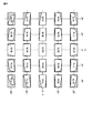
図17は、このようなプロジェクタ1の歪み補正の補正前歪み四角形と補正後矩形との関係を、投影面で見た場合を示す図であり、図18は、同様の関係を出力表示素子(マイクロミラー表示素子や液晶素子など)面で見た場合を示す図である。 FIG. 17 is a diagram showing the relationship between the distortion-corrected pre-correction rectangle and the post-correction rectangle of the projector 1 as seen on the projection plane. FIG. 18 shows the same relationship with the output display element ( It is a figure which shows the case where it sees on the surface of a micromirror display element, a liquid crystal element, etc.
図17において、白矩形は、補正後矩形a’b’c’d’であり、画像有効部分である。斜線部分は、補正前歪み四角形abcdから補正後矩形a’b’c’d’を切り抜いた残りの画像無効部分である。点kは、プロジェクタ光学系の光軸が投影面を貫く位置を表している。 In FIG. 17, a white rectangle is a corrected rectangle a′b′c′d ′, which is an image effective portion. The hatched portion is the remaining image invalid portion obtained by cutting out the corrected rectangle a′b′c′d ′ from the pre-correction distorted rectangle abcd. A point k represents a position where the optical axis of the projector optical system passes through the projection plane.
図18の斜線部分と白四角は、図17の斜線部分と白矩形にそれぞれ対応する。白四角内のパーセント表示は、出力表示素子の画素利用率を表す。h=v=0である中央の四角形は、歪み補正無しの場合を表しており、このとき画素利用率は100%である。 The hatched portion and white square in FIG. 18 correspond to the hatched portion and white rectangle in FIG. 17, respectively. The percentage display in the white square represents the pixel utilization rate of the output display element. The central square with h = v = 0 represents the case without distortion correction, and at this time, the pixel utilization rate is 100%.
歪み補正の切り抜き方法は複数存在するが、図17及び図18は、画像の横縦比を維持したまま画素利用率が向上するような切り抜き方法を採用している場合の例である。 Although there are a plurality of distortion correction clipping methods, FIGS. 17 and 18 are examples in which a clipping method that improves the pixel utilization rate while maintaining the aspect ratio of the image is employed.
また、プロジェクタの仕様としては、出力表示素子の横縦比16:9(約1.78)、スローレシオ約0.92、出力表示素子の光軸位置は下辺中央から出力表示素子高さの約20%上方である。ただし、スローレシオ=投影像横幅÷投影距離であり、スローレシオの条件は歪み補正無し時である。 Further, the specifications of the projector are as follows. The aspect ratio of the output display element is 16: 9 (about 1.78), the slow ratio is about 0.92, and the optical axis position of the output display element is about the height of the output display element from the center of the lower side. 20% above. However, slow ratio = projected image width / projection distance, and the condition of the slow ratio is when there is no distortion correction.
ところで、画像出力装置としてのPCの画像、特にWindows(登録商標)などの画面を出力する場合、PC側の横縦比(出力画素数)には自由度がある。Windowsが稼働中に横縦比を切り替えるといったことも自在に行える。例えば、横縦比1.333(800×600画素)、横縦比1.600(1280×800画素や1680×1050画素)、横縦比1.778(1600×900画素)、等々である。つまり、画面は、矩形でさえあれば良いものとなっている。 By the way, when outputting an image of a PC as an image output device, particularly a screen such as Windows (registered trademark), the aspect ratio (number of output pixels) on the PC side has a degree of freedom. It is possible to freely change the aspect ratio while Windows is in operation. For example, the aspect ratio is 1.333 (800 × 600 pixels), the aspect ratio is 1.600 (1280 × 800 pixels or 1680 × 1050 pixels), the aspect ratio is 1.778 (1600 × 900 pixels), and so on. In other words, the screen need only be a rectangle.
プロジェクタ1は、このようなPCの出力画像の横縦比に応じて出力表示素子を選択使用することで、複数の横縦比で画像を投影できるように構成されている。このようにプロジェクタ1に入力される画像の横縦比が切り替わったとしても、歪み補正は、元々の画像の横縦比つまり歪み補正無しの横縦比が維持されるようになっている。 The projector 1 is configured to project an image with a plurality of aspect ratios by selectively using an output display element according to the aspect ratio of the output image of the PC. As described above, even when the aspect ratio of the image input to the projector 1 is switched, the distortion correction maintains the aspect ratio of the original image, that is, the aspect ratio without distortion correction.
従って、歪み補正時の自由度はあまり大きくなかった。 Therefore, the degree of freedom at the time of distortion correction was not so large.
本発明は、歪み補正時の自由度を向上させることができる投影装置、画像出力装置、投影方法及び投影プログラムを提供することを目的とする。 It is an object of the present invention to provide a projection device, an image output device, a projection method, and a projection program that can improve the degree of freedom during distortion correction.
前記目的を果たすため、本発明の一態様によれば、投影装置は、画像出力装置より出力される画像信号を入力して被投影体に投影する投影装置であって、当該投影装置と前記被投影体との相対角度を取得する取得手段と、取得された前記相対角度に基づいて、前記画像出力装置に推奨する出力画素数を算出する推奨画素数算出手段と、算出された前記出力画素数を前記画像出力装置に通知する通知手段と、前記通知された前記出力画素数に応じて前記画像出力装置から出力された画像信号を、前記相対角度に基づいて、歪み補正して投影する歪み補正手段と、を備える。 In order to achieve the above object, according to an aspect of the present invention, a projection apparatus is a projection apparatus that receives an image signal output from an image output apparatus and projects the image signal onto a projection target. An acquisition unit that acquires a relative angle with the projector, a recommended pixel number calculation unit that calculates the number of output pixels recommended for the image output device based on the acquired relative angle, and the calculated number of output pixels Notification means for notifying the image output device, and distortion correction for projecting the image signal output from the image output device according to the notified number of output pixels by correcting the distortion based on the relative angle Means.
前記目的を果たすため、本発明の一態様によれば、画像出力装置は、出力した画像信号を被投影体に投影する投影装置と協働する画像出力装置であって、前記投影装置と前記被投影体との相対角度及び投影時の画角情報を取得する取得手段と、取得された前記相対角度及び前記画角情報に基づいて、歪み補正する際に出力する画像信号の推奨する出力画素数を算出する推奨画素数算出手段と、前記相対角度及び前記画角情報に基づいて、出力する画像信号を歪み補正する歪み補正手段と、算出した推奨する出力画素数で、歪み補正された前記画像信号を前記投影装置に出力する出力手段と、を備える。 In order to achieve the above object, according to one aspect of the present invention, an image output apparatus is an image output apparatus that cooperates with a projection apparatus that projects an output image signal onto a projection target, the projection apparatus and the target Acquisition means for acquiring relative angle with the projection body and angle of view information at the time of projection, and the recommended number of output pixels of the image signal to be output when correcting distortion based on the acquired relative angle and angle of view information The recommended pixel number calculating means for calculating the distortion, the distortion correcting means for correcting the distortion of the image signal to be output based on the relative angle and the angle-of-view information, and the image whose distortion is corrected by the calculated recommended number of output pixels Output means for outputting a signal to the projection apparatus.
前記目的を果たすため、本発明の一態様によれば、投影方法は、画像出力装置より出力される画像信号を入力して被投影体に投影する投影装置における投影方法であって、当該投影装置と前記被投影体との相対角度を取得する相対角度取得工程と、前記相対角度取得工程により取得された前記相対角度に基づいて、前記画像出力装置に推奨する出力画素数を算出する推奨画素数算出工程と、前記推奨画素数算出工程により算出された前記出力画素数を前記画像出力装置に通知する通知工程と、前記通知された前記出力画素数に応じて前記画像出力装置から出力された画像信号を、前記相対角度取得工程により取得された前記相対角度に基づいて、歪み補正して投影する歪み補正工程と、を備える。 In order to achieve the above object, according to one aspect of the present invention, a projection method is a projection method in a projection apparatus that inputs an image signal output from an image output apparatus and projects the image signal onto a projection target, the projection apparatus And a relative angle acquisition step of acquiring a relative angle between the projection target and the recommended number of pixels for calculating the number of output pixels recommended for the image output device based on the relative angle acquired by the relative angle acquisition step A calculation step, a notification step of notifying the image output device of the number of output pixels calculated in the recommended pixel number calculation step, and an image output from the image output device in accordance with the notified number of output pixels A distortion correction step of correcting and projecting the signal based on the relative angle acquired by the relative angle acquisition step.
前記目的を果たすため、本発明の一態様によれば、投影プログラムは、画像出力装置より出力される画像信号を入力して被投影体に投影する投影装置におけるコンピュータに、当該投影装置と前記被投影体との相対角度を取得することと、取得された前記相対角度に基づいて、前記画像出力装置に推奨する出力画素数を算出することと、算出された前記出力画素数を前記画像出力装置に通知することと、前記通知された前記出力画素数に応じて前記画像出力装置から出力された画像信号を、前記相対角度に基づいて、歪み補正して投影することと、を実行させる。 In order to achieve the above object, according to one aspect of the present invention, a projection program receives, on a computer in a projection apparatus that inputs an image signal output from an image output apparatus and projects the image signal on the projection target, the projection apparatus and the subject. Obtaining a relative angle with the projector, calculating a recommended number of output pixels for the image output device based on the obtained relative angle, and calculating the calculated output pixel number to the image output device. And the image signal output from the image output device according to the notified number of output pixels is subjected to distortion correction based on the relative angle and projected.
本発明によれば、歪み補正時の自由度を向上させることができる投影装置、画像出力装置、投影方法及び投影プログラムを提供できる。 According to the present invention, it is possible to provide a projection device, an image output device, a projection method, and a projection program that can improve the degree of freedom during distortion correction.
[第1実施形態]
第1実施形態について図面を参照して説明する。本実施形態に係る投影装置は、出力表示素子としてマイクロミラー表示素子を用いたDigital Light Processing(DLP)(登録商標)方式を用いている。本実施形態に係る投影装置としてのプロジェクタ1は、図1(A)に示すように、本実施形態に係る画像出力装置としてのパーソナルコンピュータ(PC)4に接続され、該PC4の出力画像を受けて、スクリーン2に投影表示するものである。
[First Embodiment]
A first embodiment will be described with reference to the drawings. The projection apparatus according to the present embodiment uses a digital light processing (DLP) (registered trademark) system using a micromirror display element as an output display element. As shown in FIG. 1A, a projector 1 as a projection apparatus according to this embodiment is connected to a personal computer (PC) 4 as an image output apparatus according to this embodiment, and receives an output image of the
このプロジェクタ1の構成の概略を図1(B)に示す。プロジェクタ1は、入出力コネクタ部11と、入出力インターフェース(I/F)12と、画像変換部13と、投影処理部14と、マイクロミラー素子15と、光源部16と、ミラー17と、投影レンズ18と、CPU19と、メインメモリ20と、プログラムメモリ21と、操作部22と、姿勢センサ23と、音声処理部24と、スピーカ25と、レンズ調整部26と、姿勢調整部27と、電動脚部28と、システムバスSBと、を有する。
A schematic configuration of the projector 1 is shown in FIG. The projector 1 includes an input /
入出力コネクタ部11には、例えばピンジャック(RCA)タイプのビデオ入力端子や、D−sub15タイプのRGB入力端子といった端子が設けられており、アナログ画像信号が入力される。入力された画像信号は、入出力I/F12及びシステムバスSBを介して画像変換部13に入力される。入力された各種規格のアナログ画像信号は、デジタル画像信号に変換される。なお、入出力コネクタ部11には、例えばHDMI(登録商標)端子等も設けられ、アナログ画像信号のみならずデジタル画像信号も入力され得るようにしてもよい。さらに、Extended Display Identification Data(EDID)として規格化されているデータ形式で、様々な情報を出力することも可能となっている。また、入出力コネクタ部11には、アナログ又はデジタル信号による音声信号が入力される。入力された音声信号は、入出力I/F12及びシステムバスSBを介して音声処理部24に入力される。また、入出力コネクタ部11には、例えばRS232C端子やUSB端子も設けられており、それらを介してもPC4とのデータのやり取りが行えるようになっている。
The input /
画像変換部13は、スケーラとも称される。画像変換部13は、入力された画像データについて、解像度数、階調数等を調整する変換を行い、投影に適した所定のフォーマットの画像データを生成する。画像変換部13は、変換した画像データを投影処理部14へ送信する。必要に応じて画像変換部13は、On Screen Display(OSD)用の各種動作状態を示すシンボルを重畳した画像データを、加工画像データとして投影処理部14に送信する。また、画像変換部13は、必要に応じて投影画像の幾何学変換を行い、投影状態に応じてスクリーン等の被投影体に適切な形状で画像が投影されるようにする歪み補正処理を実施する。
The image conversion unit 13 is also referred to as a scaler. The image conversion unit 13 performs conversion for adjusting the number of resolutions, the number of gradations, and the like for the input image data, and generates image data in a predetermined format suitable for projection. The image conversion unit 13 transmits the converted image data to the
光源部16は、赤(R)、緑(G)、青(B)の原色光を含む複数色の光を射出する。ここで、光源部16は、複数色の色を時分割で順次射出するように構成されている。光源部16から射出された光は、ミラー17で全反射し、マイクロミラー素子15に入射する。
The
マイクロミラー素子15は、アレイ状に配列された複数の微小ミラーを有する。各微小ミラーは、高速でオン/オフ動作して、光源部16から照射された光を投影レンズ18の方向に反射させたり、投影レンズ18の方向からそらしたりする。マイクロミラー素子15には、微小ミラーが例えばHD+やWXGA++と称される横1600画素×縦900画素分だけ並べられている。各微小ミラーにおける反射によって、マイクロミラー素子15は、例えばHD+解像度の画像を形成する。このように、マイクロミラー素子15は空間的光変調素子として機能する。
The
投影処理部14は、画像変換部13から送信された画像データに応じて、その画像データが表す画像を表示させるため、マイクロミラー素子15を駆動する。すなわち、投影処理部14は、マイクロミラー素子15の各微小ミラーをオン/オフ動作させる。ここで投影処理部14は、マイクロミラー素子15を高速に時分割駆動する。単位時間の分割数は、所定のフォーマットに従ったフレームレート、例えば60[フレーム/秒]と、色成分の分割数と、表示階調数とを乗算して得られる数である。また、投影処理部14は、マイクロミラー素子15の動作と同期させて光源部16の動作も制御する。すなわち、投影処理部14は、各フレームを時分割して、フレーム毎に全色成分の光を順次射出するように光源部16の動作を制御する。
The
投影レンズ18は、マイクロミラー素子15から導かれた光を、例えばスクリーン2等の被投影体に投影する光に調整する。したがって、マイクロミラー素子15による反射光で形成された光像は、投影レンズ18を介して、スクリーン2等の被投影体に投影され表示される。投影レンズ18は、ズーム機構を有しており、投影される画像の大きさを変更する機能を有する。また、投影レンズ18は、投影画像の合焦状態を調整するためのピント(フォーカス)調整機構を有する。このように、投影処理部14、マイクロミラー素子15、光源部16及び投影レンズ18等は、画像を投影する投影部として機能する。
The
音声処理部24は、PCM音源等の音源回路を備える。入出力コネクタ部11から入力されたアナログ音声データに基づいて、又は投影動作時に与えられたデジタル音声データをアナログ化した信号に基づいて、音声処理部24は、スピーカ25を駆動して拡声放音させる。また、音声処理部24は、必要に応じてビープ音等を発生させる。スピーカ25は、音声処理部24から入力された信号に基づいて音声を射出する一般的なスピーカである。
The
CPU19は、画像変換部13、投影処理部14、音声処理部24、レンズ調整部26、及び姿勢調整部27の動作を制御する。このCPU19は、メインメモリ20及びプログラムメモリ21と接続されている。メインメモリ20は、例えばSRAMで構成される。メインメモリ20は、CPU19のワークメモリとして機能する。プログラムメモリ21は、電気的に書き換え可能な不揮発性メモリで構成される。プログラムメモリ21は、CPU19が実行する動作プログラムや各種定型データ等を記憶する。また、CPU19は、操作部22と接続されている。操作部22は、プロジェクタ1の本体に設けられるキー操作部と、プロジェクタ1専用の図示しないリモートコントローラからの赤外光を受光する赤外線受光部と、を含む。操作部22は、ユーザが本体のキー操作部又はリモートコントローラで操作したキーに基づくキー操作信号をCPU19に出力する。CPU19は、メインメモリ20及びプログラムメモリ21に記憶されたプログラムやデータを用いて、操作部22からのユーザの指示に応じてプロジェクタ1の各部の動作を制御する。
The
姿勢センサ23は、例えば3軸の加速度センサ、方位を検出する方位センサを有する。加速度センサは、重力方向に対するプロジェクタ1の姿勢角すなわち、ピッチ、及びロールの各角度を検出する。ヨー角については、方位センサで検出される基準方位に対する相対方位として、検出される。姿勢センサ23は、検出結果をCPU19に出力する。
The
レンズ調整部26は、操作部22のユーザ操作によるズーム変更指示に応じて、CPU19の制御の下、投影レンズ18のズーム機構を駆動させる。レンズ調整部26によって、ズーム機構が駆動される結果、投影画像の大きさが変化する。また、レンズ調整部26は、CPU19の指示の下、投影レンズ18の合焦レンズを駆動させる。
The
電動脚部28は、姿勢調整機構として、プロジェクタ1の姿勢を変更する。すなわち、電動脚部28は、脚の長さを変更させることで、プロジェクタ1の水平度を調整することができる。姿勢調整部27は、CPU19の指示の下、電動脚部28を駆動させる。
The
以下、本実施形態に係るプロジェクタ1の動作を説明する。
まず、プロジェクタ1の投影動作を説明する。この投影動作は、CPU19の制御の下、投影処理部14が実行するものである。光源部16の動作は、投影処理部14により制御される。投影処理部14は、光源部16内の各色を発する半導体レーザやLEDのオン又はオフや、それら光源と蛍光体との組み合わせなどを変化させることで、例えば赤色光(R)、緑色光(G)、青色光(B)の3色の光を、光源部16から順次射出させる。投影処理部14は、光源部16からマイクロミラー素子15に順次、赤色光、緑色光、及び青色光を入射させる。
Hereinafter, the operation of the projector 1 according to the present embodiment will be described.
First, the projection operation of the projector 1 will be described. This projection operation is executed by the
マイクロミラー素子15は、各色の光について微小ミラー毎(画素毎)に、画像データに基づく階調が高い程入射した光を投影レンズ18に導く時間を長くし、階調が低い程入射した光を投影レンズ18に導く時間を短くする。すなわち、投影処理部14は、階調が高い画素に対応する微小ミラーが長時間オン状態となるように、階調が低い画素に対応する微小ミラーが長時間オフ状態となるように、マイクロミラー素子15を制御する。このようにすることで、投影レンズ18から射出される光について、微小ミラー毎(画素毎)に各色の階調を表現できる。
The
フレーム毎に、微小ミラーがオンになっている時間で表現された階調を各色について組み合わせることでカラー画像が表現される。以上のようにして、投影レンズ18からは、画像が表現された投影光が射出される。この投影光が、例えばスクリーン2に投影されることで、スクリーン2等にはカラー画像が表示される。
For each frame, a color image is expressed by combining the gradation expressed by the time when the micromirror is on for each color. As described above, projection light expressing an image is emitted from the
なお、前記説明では、赤色光、緑色光、青色光の3色を用いるプロジェクタの例を示したが、マゼンタやイエロー等の補色や、白色光等を組み合わせて画像を形成するように、これら色の光を射出できるようにプロジェクタが構成されてもよい。 In the above description, an example of a projector that uses three colors of red light, green light, and blue light has been described. However, these colors may be used to form an image by combining complementary colors such as magenta and yellow, white light, and the like. The projector may be configured so as to be able to emit the light.
次に、本実施形態に係る歪み補正処理について説明する。この歪み補正処理は、例えばスクリーン2といった被投影体に、例えばできるだけ大きく、歪みのない長方形状に、映像を投影するために、入力画像情報を射影変換することで行われる。そのため、例えばプロジェクタ1が設置される際に歪み補正処理用のパラメータを決定し、実際の画像投影時に、該歪み補正処理パラメータに基づく歪み補正処理を実施するものである。
Next, the distortion correction process according to the present embodiment will be described. This distortion correction processing is performed by projective transformation of input image information in order to project an image on a projection object such as a
本実施形態における歪み補正動作の一例を表すフローチャートを図2に示す。ここで、図2(A)はプロジェクタ側の動作、図2(B)はPC側の動作である。 A flowchart showing an example of the distortion correction operation in this embodiment is shown in FIG. 2A shows the operation on the projector side, and FIG. 2B shows the operation on the PC side.
プロジェクタ1は、CPU19で実行される投影プログラムの一部として、このフローチャートに対応するプログラムをプログラムメモリ21に記憶している。
The projector 1 stores a program corresponding to this flowchart in the
プロジェクタ側では、まずステップS101において、CPU19は、プロジェクタ1とスクリーン2との相対角度を取得する。すなわち、プロジェクタ1が水平ベース等の上に設置される際、通常は、スクリーン2に平行にプロジェクタ1を載置して電源を投入し、投影レンズ18から出射された光がスクリーン2に投射されるように、ユーザはプロジェクタ1の姿勢を変更修正する。このプロジェクタ1の姿勢の変更操作時のプロジェクタ1の動きを姿勢センサ23により検出することで、CPU19は、プロジェクタ1とスクリーン2との相対角度を知ることができる。
On the projector side, first, in step S101, the
次に、処理はステップS102に進む。このステップS102において、CPU19は、画角情報(プロジェクタ仕様)を取得する。この画角情報としては、例えば、スローレシオ、ズーム値、レンズシフト量などであり、不図示センサにより測定したり、プログラムメモリ21に当該プロジェクタの規定値として記憶されている値あるいはユーザ操作により変更された値を読み出ししたり、する等によって取得することができる。
Next, the process proceeds to step S102. In step S102, the
こうしてプロジェクタ1とスクリーン2との相対角度及び画角情報を取得したならば、処理はステップS103に進む。このステップS103においては、CPU19は、前記取得されている相対角度及び画角情報に基づいて、補正前歪み四角形abcdの形状を判別(認識)し、画像変換部13で投影画像をスクリーン2で矩形画像となるように幾何学補正するための歪み補正処理パラメータを決定する。なお、歪み補正の切り抜き方法は複数存在するが、ここでは、例えば、画素利用率が向上するような切り抜き方法を採用するものとする。
If the relative angle and field angle information between the projector 1 and the
図3は、本実施形態におけるプロジェクタ1の歪み補正の補正前歪み四角形abcdと補正後矩形a’b’c’d’との関係を、投影面で見た場合を示す図であり、図4は、同じく出力表示素子面で見た場合を示す図である。これは、図17及び図18のプロジェクタ仕様と同じプロジェクタ仕様で、例えば画素利用率が最大になるように補正後矩形の横縦比と切り抜き位置を決定した場合を示している。なお、図3中の補正後矩形内の数字は、横縦比(幅÷高さ)を表している。 FIG. 3 is a diagram illustrating a relationship between the uncorrected distortion rectangle abcd and the corrected rectangle a′b′c′d ′ of the projector 1 according to the present embodiment when viewed on the projection plane. These are figures which show the case where it sees similarly on the output display element surface. This shows a case where the aspect ratio and cutout position of the corrected rectangle are determined so as to maximize the pixel utilization rate, for example, with the same projector specifications as those of FIGS. 17 and 18. The numbers in the corrected rectangle in FIG. 3 represent the aspect ratio (width / height).
本実施形態によれば、図3と図17の比較により、水平方向の角度hの絶対値が大きくなるに従って横縦比が大きくなり、垂直方向の角度vの絶対値が大きくなるに従って横縦比が小さくなる傾向が判別できる。水平方向角度hと垂直方向角度vが共にゼロではない場合、横縦比は垂直方向角度vよりも水平方向角度hの方の影響が大きい。つまり、横長になり易い。本実施形態の図4の画素利用率のそれぞれは、図18のそれらよりも大きい。ただし、周辺部(h=v=30°等)の画素利用率の上昇は僅かである(h=v=30°の画素利用率が図18の41.6%から図4の42.0%に僅かに上昇)。 According to the present embodiment, by comparing FIG. 3 and FIG. 17, the aspect ratio increases as the absolute value of the angle h in the horizontal direction increases, and the aspect ratio increases as the absolute value of the angle v in the vertical direction increases. It is possible to discriminate the tendency that becomes smaller. When both the horizontal direction angle h and the vertical direction angle v are not zero, the aspect ratio is more influenced by the horizontal direction angle h than the vertical direction angle v. That is, it tends to be horizontally long. Each of the pixel utilization rates in FIG. 4 of this embodiment is larger than those in FIG. However, the increase in the pixel usage rate in the peripheral portion (h = v = 30 °, etc.) is slight (the pixel usage rate at h = v = 30 ° is 41.6% in FIG. 18 to 42.0% in FIG. 4). Slightly increased).
こうして決定された歪み補正処理パラメータに従って実際の歪み補正処理を実施すると、画像の横縦比が変わってしまうので、例えばPC4側で画像として円を表示させようとしても、実際に投影表示される画像では、その円が楕円として表示されてしまう。
When the actual distortion correction processing is performed according to the distortion correction processing parameters thus determined, the aspect ratio of the image changes. For example, even if a circle is displayed as an image on the
そこで、本実施形態では、歪み補正処理パラメータ決定後、PC4と通信して、以下のような処理を実行する。
すなわち、PC4側においては、不図示CPUが、同じく不図示のメモリに格納されたプログラムに従って動作し、まず、ステップS401において、プロジェクタ1に対して、現在の出力画素数つまりデフォルト出力画素数を通知する。
Therefore, in the present embodiment, after determining the distortion correction processing parameter, the following processing is executed by communicating with the
That is, on the
プロジェクタ1のCPU19は、ステップS104において、このPC4から通知されるのデフォルト出力画素数を入出力コネクタ部11及び入出力I/F12を介して受信し、プログラムメモリ21に格納する。なお、このようなデフォルト出力画素数の取得動作は、ステップS103の後に限るものではなく、これよりも前の任意の時点に行っても構わない。
In step S <b> 104, the
そして、プロジェクタ1の処理はステップS105に進む。このステップS105においては、CPU19は、前記取得されている相対角度及び画角情報に基づいて、あるいは、前記決定されている歪み補正処理パラメータに基づいて、さらには、プログラムメモリ21に格納したPC4のデフォルト出力画素数に基づいて、PC推奨画素数(水平画素数、垂直画素数)を算出する。これは、歪み補正処理後の画像が元の画像の横縦比と同じになるためには、どのような横縦比の画像であれば良いのかを算出し、その横縦比の画素数をPC推奨画素数として求めるものである。ここで、例えば横縦比1.600の画素数としては、1280×800画素だけでなく1680×1050画素もある。そこで、PC推奨画素数としては、複数の候補が算出され得る。こうして、相対角度がh=v=0°でなければ、投影装置の出力表示素子の横縦比と異なるPC推奨画素数が算出される。
Then, the process of the projector 1 proceeds to step S105. In this step S105, the
なお、算出されるPC推奨画素数については、その横縦比が所定の範囲になるというような制限や、PC4のデフォルト出力画素数に近い出力画素数とするというような制限等、何らかの制限を設けることで、PC推奨画素数として多数の候補が算出されることを防止できる。 It should be noted that the PC recommended pixel number to be calculated has some limitations such as a limitation that the aspect ratio is within a predetermined range and a limitation that the output pixel number is close to the default output pixel number of PC4. By providing, it is possible to prevent a large number of candidates from being calculated as the PC recommended pixel number.
こうしてPC推奨画素数が算出されたならば、処理はステップS106に進む。このステップS106においては、CPU19は、算出されたPC推奨画素数を入出力I/F12及び入出力コネクタ部11を介してPC4に通知する。ここで、前述したように、PC推奨画素数として複数の候補が存在する場合には、それら複数の候補を通知することになる。なお、この通知は、EDID形式等、PC4側でその内容を判別できる形式であれば、どのようなデータ形式で行っても構わない。
If the PC recommended pixel count is thus calculated, the process proceeds to step S106. In step S106, the
PC4側においては、ステップS402において、不図示CPUは、このプロジェクタ1から送られてきたPC推奨画素数の通知を受信して、不図示メモリに格納する。
On the
以上のような、プロジェクタ1とPC4との間の通信が終了したならば、実際の画像投影が行われる。
When the communication between the projector 1 and the
すなわち、実際に画像投影を行おうとする際には、PC4の不図示CPUは、処理をステップS403に進める。このステップS403において、不図示CPUは、出力画素数を前記不図示メモリに格納してあるPC推奨画素数に変更する。なお、PC推奨画素数として複数の候補がある場合には、例えば、候補の内の最大の画素数を選択するとか、現在の出力画素数に近いものを選択する等、そのうちの一つを任意の基準で選択して使用する。そして、処理はステップS404に進む。ステップS404において、不図示CPUは、その変更した推奨画素数で表示対象画像の画像信号をプロジェクタ1に出力する。
That is, when actually projecting an image, the CPU (not shown) of the
プロジェクタ1では、ステップS107において、CPU19は、入出力コネクタ部11及び入出力I/F12を介してこの表示対象画像の画像信号を受信し、それを画像変換部13に入力する。そして、処理はステップS108に進む。このステップS108では、CPU19は、画像変換部13に、その入力された表示対象画像の画像信号に対して、前記ステップS103で決定した歪み補正処理パラメータに従った歪み補正処理を実施させる。そして、処理はステップS109に進む。ステップS109において、CPU19は、投影処理部14に、前記画像変換部13で歪み補正処理された補正後画像を投影処理させる。
In the projector 1, in step S <b> 107, the
具体的には、図3、図4の例で言えば、例えば、hが0°、vが+15°〜+30°のときに、横縦比として、1.33となる横800画素、縦600画素のような推奨する出力画素数を通知して、投影させるようにすれば、画素利用率をより高めた(明るく、高解像度の)投影を行うことができる。 Specifically, in the example of FIGS. 3 and 4, for example, when h is 0 ° and v is + 15 ° to + 30 °, the horizontal aspect ratio is 1.33, which is 1.33, and the vertical length is 600. If the recommended number of output pixels such as pixels is notified and projected, it is possible to perform projection with higher pixel utilization (brighter and higher resolution).
以上のように、プロジェクタ1とPC4との相対角度を取得して、該相対角度に基づいてPC4の推奨画素数を算出(選定)し、それをPC4に通知することで、PC4からその推奨出力画素数の画像信号を受けることができ、その画像信号に対して前記相対角度に基づく歪み補正を実施して投影するようにしているので、元の画像の横縦比を維持したまま、歪み補正時の自由度を向上させることができる。
As described above, the relative angle between the projector 1 and the
また、歪み補正処理やPC推奨画素数の算出においては、プロジェクタの出力表示素子の画素利用率を向上させるような補正後矩形a’b’c’d’の切り抜き位置や出力画素数を求めるので、画素利用率をより高めた(明るく、高解像度の)投影を行うことができる。 Further, in the distortion correction processing and the calculation of the PC recommended pixel number, the cut-out position and the output pixel number of the corrected rectangle a′b′c′d ′ that improve the pixel utilization rate of the output display element of the projector are obtained. Projection with higher pixel utilization (brighter and higher resolution) can be performed.
また、PC推奨画素数は、出力画素数の横縦比が所定の範囲になるような出力画素数を算出(選定)するようにしているので、横縦比が横長になりすぎたり、縦長になりすぎたりすることを防ぐことができる。 In addition, the PC recommended pixel number is calculated (selected) so that the aspect ratio of the number of output pixels falls within a predetermined range. Therefore, the aspect ratio becomes too long or long. It can prevent becoming too much.
また、PC4のデフォルトの出力画素数を予め取得して、それに近い出力画素数をPC推奨画素数として算出(選定)するようにしているので、PC4のデフォルト横縦比から大きく外れることを防ぐことができる。 In addition, since the default output pixel number of PC4 is acquired in advance and the output pixel number close to that is calculated (selected) as the PC recommended pixel number, it is prevented from greatly deviating from the default aspect ratio of PC4. Can do.
また、PC推奨画素数として候補を複数算出(選定)してPC4に通知するようにしているので、PC4側で使い易い出力画素数を選択し易い。
Further, since a plurality of candidates are calculated (selected) as the PC recommended pixel number and notified to the
さらに、歪み補正処理やPC推奨画素数の算出において、プロジェクタ1の画角情報も考慮することで、投影レンズ18が備えるズームレンズ調節により投影時の画角が変わる場合にも対処可能である。
Furthermore, by considering the angle of view information of the projector 1 in the distortion correction processing and the calculation of the PC recommended pixel number, it is possible to cope with the case where the angle of view at the time of projection is changed by adjusting the zoom lens included in the
また、姿勢センサ23で検出された検出結果に基づいて、スクリーン2との相対角度を取得するようにしているので、測距等をしなくても、即座に適切な相対角度を取得することができる。
Further, since the relative angle with respect to the
[変形例]
なお、歪み補正処理は、プロジェクタ1側ではなくPC4側で実施することも可能である。図5は、この場合の歪み補正動作の一例を表すフローチャートである。ここで、図5(A)はプロジェクタ1側の動作、図5(B)はPC4側の動作である。
[Modification]
Note that the distortion correction processing can be performed not on the projector 1 side but on the
この場合には、プロジェクタ1のCPU19は、前述したようなステップS101及びステップS102において、プロジェクタ1とスクリーン2との相対角度及び画角情報を取得する。その後、処理はステップS111に進む。このステップS111においては、CPU19は、さらに、プログラムメモリ21に予め格納されている、当該プロジェクタ1の出力表示素子の画素数を取得する。そして、処理はステップS112に進む。このステップS112においては、CPU19は、前記取得されている相対角度、画角情報及び出力表示素子画素数を、入出力I/F12及び入出力コネクタ部11を介してPC4に通知する。
In this case, the
PC4側においては、不図示CPUが、ステップS411において、このプロジェクタ1から送られてきた相対角度、画角情報及び出力表示素子画素数を受信して、不図示メモリに格納する。その後、処理はステップS412に進む。このステップS412においては、不図示CPUは、不図示メモリに格納している相対角度、画角情報及び出力表示素子画素数に基づいて、歪み補正処理パラメータを決定する。なお、歪み補正の切り抜き方法は複数存在するが、ここでは、例えば、画素利用率が向上するような切り抜き方法を採用するものとする。そして、処理はステップS413に進む。このステップS413においては、不図示CPUは、前記不図示メモリに格納している相対角度、画角情報及び出力表示素子画素数に基づいて、あるいは、前記決定されている歪み補正処理パラメータに基づいて、さらには、当該PC4に設定されている現在の出力画素数つまりデフォルト出力画素数に基づいて、PC推奨画素数(水平画素数、垂直画素数)を算出する。このとき、算出されるPC推奨画素数の横縦比が所定の範囲になるというような制限や、前記デフォルト出力画素数に近い出力画素数とするというような制限等、何らかの制限を設けることで、一つのPC推奨画素数を決定する。
On the
以上のようにして歪み補正処理パラメータとPC推奨画素数とを決定したならば、実際の画像投影が行われることになる。 When the distortion correction processing parameter and the PC recommended pixel number are determined as described above, actual image projection is performed.
すなわち、実際に画像投影を行おうとする際には、PC4の不図示CPUは、処理をステップS414に進める。このステップS414において、不図示CPUは、出力対象画像の出力画素数を前記決定したPC推奨画素数となるように変換する。その後、処理はステップS415に進む。ステップS415において、不図示CPUは、出力画素数変換後の表示対象画像の画像信号に対して、前記ステップS412で決定した歪み補正処理パラメータに従った歪み補正処理を実施する。そして、処理はステップS416に進む。ステップS416において、不図示CPUは、その歪み補正処理を施した補正後画像の画像信号をプロジェクタ1に出力する。
That is, when actually projecting an image, the CPU (not shown) of the
プロジェクタ1では、ステップS113において、CPU19は、入出力コネクタ部11及び入出力I/F12を介してこの補正後画像の画像信号を受信し、それを画像変換部13に入力し、階調数等を調整する変換を行わせて投影に適した所定のフォーマットの画像データを生成する。その後は、処理はステップS109に進んで、CPU19は、その変換した画像データを投影処理部14へ送信させて、投影処理させる。
In the projector 1, in step S <b> 113, the
以上のように、PC4側で、プロジェクタ1とスクリーン2との相対角度及び投影時の画角情報を取得し、それらに基づいて出力する画像信号を歪み補正すると共に、出力する画像信号の推奨する出力画素数を算出して、その出力画素数で歪み補正された画像信号をプロジェクタ1に出力するようにすることで、前記第1実施形態と同様、元の画像の横縦比を維持したまま、歪み補正時の自由度を向上させることができる。
As described above, on the
また、PC4側で、プロジェクタ1に前記相対角度及び前記画角情報に基づいて、プロジェクタ1の出力表示素子の画素利用率を向上させるように歪み補正することにより、画素利用率をより高めた(明るく、高解像度の)投影を行うことができる。
Further, on the
また、プロジェクタ1の出力表示素子の画素数も取得して、その取得された画素数にも基づいて、推奨する出力画素数を算出するようにしているので、プロジェクタ1側が適切に投影することができる。 Further, the number of pixels of the output display element of the projector 1 is also acquired, and the recommended number of output pixels is calculated based on the acquired number of pixels, so that the projector 1 side can appropriately project. it can.
[第2実施形態]
第2実施形態について説明する。ここでは、第1実施形態との相違点について説明し、同一の部分については、同一の符号を付してその説明を省略する。本実施形態では、歪み補正の際にロール角も調整し得るようにすることで、さらに画素利用率を高めることができるようにしたものである。
[Second Embodiment]
A second embodiment will be described. Here, differences from the first embodiment will be described, and the same portions will be denoted by the same reference numerals and description thereof will be omitted. In the present embodiment, the pixel utilization rate can be further increased by adjusting the roll angle during distortion correction.
そのため、プロジェクタ1の筐体を支持するための電動脚部28は、プロジェクタ1の姿勢及びロール角を変更する姿勢及びロール角調整機構として機能する。すなわち、電動脚部28は、図6に示すように、各脚28Aの長さを独立して変更させることで、プロジェクタ1の水平度を調整したり、プロジェクタ光学系の光軸方向(投影方向)を変えずに、すなわち光軸周りに回転させることでロール角を調整したりすることができるように構成されている。
Therefore, the
ここで、ロール角について説明する。
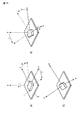
図7は、図15の状態の後、z軸を回転軸として矢印方向に角度rだけ回転させた場合を表している。図8はその詳細である。ここで、図8(A)及び(B)は、図16(A)及び(B)と同様である。図8(C)において、z軸を回転軸として矢印方向に三つ目の角度である角度rだけ回転させる。これにより、x軸とy軸はそれぞれ点線に移動する。図8(D)の三つの矢印は、先ず水平方向に角度hだけ回転させ、次に垂直方向に角度vだけ回転させ、さらにロール角度rだけ回転させた後のプロジェクタ座標系である。このとき、x軸は、もはや水平ベース3に対して平行ではない。
Here, the roll angle will be described.
FIG. 7 shows a case where the z-axis is rotated as an axis of rotation after the state of FIG. 15 by an angle r in the direction of the arrow. FIG. 8 shows the details. Here, FIGS. 8A and 8B are the same as FIGS. 16A and 16B. In FIG. 8C, the third axis is rotated by an angle r that is the third angle in the direction of the arrow with the z axis as the rotation axis. Thereby, the x-axis and the y-axis move to the dotted lines, respectively. The three arrows in FIG. 8D are the projector coordinate system after first being rotated by the angle h in the horizontal direction, then rotated by the angle v in the vertical direction, and further rotated by the roll angle r. At this time, the x-axis is no longer parallel to the
このようにロールさせると、スクリーン2に投影される補正前歪み四角形abcdの形状が変化するため、その内部で切り抜かれる補正後矩形a’b’c’d’も変化させることができる。
When rolled in this manner, the shape of the pre-correction distorted quadrangle abcd projected onto the
本実施形態は、この点に着目し、通常であればロールを無くしてから歪み補正を行うのに対し、本実施形態は積極的にロールを加えることで、歪み補正の自由度を上げようとするものである。 The present embodiment pays attention to this point, and in the normal case, distortion correction is performed after eliminating the roll, whereas this embodiment attempts to increase the degree of freedom of distortion correction by actively adding the roll. To do.
例えば、図7のように適切なロールを加えると、その補正前歪み四角形abcdは、図15のロールが無い状態のそれよりも大きくなる。そのため、その内部で切り抜かれる補正後矩形a’b’c’d’について、そのサイズを大きくしたり、その画像の横縦比を変更したり、画素利用率を向上させたり、することができる。 For example, when an appropriate roll is added as shown in FIG. 7, the pre-correction distortion rectangle abcd becomes larger than that in the state without the roll shown in FIG. Therefore, it is possible to increase the size of the corrected rectangle a′b′c′d ′ cut out inside the image, change the aspect ratio of the image, and improve the pixel utilization rate. .
加えるロールの角度であるロール角rは、プロジェクタ1のスクリーン2に対する水平及び垂直方向の角度h,vの組み合わせにより一義的に算出される。例えば、以下の(1)式のような算出式により、ロール角rを算出できる。

但し、(1)式中のsgnは符号関数であり、詳細は、以下の(2)式の通りである。この符号関数sgnにより、hv=0の場合、つまり水平方向角度hと垂直方向角度vのどちらか一方または両方がゼロの場合には、ロール角rはゼロ、hv>0のとき、つまり水平方向角度hと垂直方向角度vの符号が同じ場合には、ロール角rは正、hv<0のとき、つまり水平方向角度hと垂直方向角度vの符号が異なる場合には、ロール角rは負になるようになっている。
前記(1)式によると、h=v=30°のときロール角rは、約16.1°と求まる。 According to the equation (1), the roll angle r is about 16.1 ° when h = v = 30 °.
以下、本実施形態に係るプロジェクタ1の動作を、本実施形態における歪み補正動作の一例を表す図9のフローチャートを参照して説明する。
すなわち、前記第1実施形態と同様にして、歪み補正処理パラメータを決定し、PC4からデフォルトの出力画素数を受信した後、本実施形態では、処理はステップS121に進む。このステップS121においては、CPU19は、ユーザが操作部22を用いて設定した動作モードとして、ロール角変更モードが選択されているか否かを判定する。ロール角度変更モードが選択されていないと判定されたとき、処理はステップS105に進んで、前記第1実施形態と同様の動作を実行する。
Hereinafter, the operation of the projector 1 according to the present embodiment will be described with reference to the flowchart of FIG. 9 showing an example of the distortion correction operation in the present embodiment.
That is, after determining the distortion correction processing parameters and receiving the default number of output pixels from the
これに対して、ステップS121においてロール角変更モードが選択されていると判定されたときには、処理はステップS122に進む。このステップS122において、CPU19は、ステップS101で取得した相対角度の内、水平方向の角度hがゼロでないかどうか判別する。この水平方向の角度hがゼロであれば、処理は前記ステップS105に進み、前記第1実施形態と同様の動作を実行することなる。
On the other hand, when it is determined in step S121 that the roll angle change mode is selected, the process proceeds to step S122. In step S122, the
一方、ステップS122において、水平方向の角度hが0でないと判別した場合には、処理はステップS123に進む。このステップS123において、CPU19は、ステップS101で取得した相対角度の内、垂直方向の角度vがゼロでないかどうか判別する。この垂直方向の角度vがゼロであれば、処理は前記ステップS105に進み、前記第1実施形態と同様の動作を実行することなる。
On the other hand, if it is determined in step S122 that the horizontal angle h is not 0, the process proceeds to step S123. In step S123, the
そして、ステップS123において、垂直方向の角度vがゼロでないと判別した場合、つまり、水平及び垂直方向の角度h,vが両方ともゼロでないと判別した場合には、処理はステップS124に進む。このステップS124では、CPU19は、例えば前述した(1)式により、画素利用率が向上するようなロール角rを決定する。そしてその後、ステップS125において、その決定したロール角rが電動脚部28によって変更可能な範囲内であるか否かを判別する。ロール角rが変更可能範囲内でなければ、処理はステップS126に進む。このステップS126において、CPU19は、ユーザにロール角変更できない旨を通知する。これは、例えば、音声処理部24を制御して、警告音をスピーカ25から発せさせたり、画像変換部13を制御して警告シンボルをOSDとして重畳した画像データを作成させ、スクリーン2に投影させたりすることで行う。その後、処理は前記ステップS105に進み、前記第1実施形態と同様の動作を実行することなる。
If it is determined in step S123 that the vertical angle v is not zero, that is, if it is determined that both the horizontal and vertical angles h and v are not zero, the process proceeds to step S124. In step S124, the
一方、ステップS125において、ロール角rが変更可能範囲内であると判別した場合には、処理はステップS127に進む。そして、このステップS127において、CPU19は、前記ステップS124で決定したロール角rに従って、姿勢調整部27に電動脚部28を駆動させて、プロジェクタ1のロール角を変更する。その後、処理はステップS128に進む。このステップS128において、CPU19は、前記ステップS124で決定したロール角度を考慮して、歪み補正処理パラメータの再決定を行う。すなわち、相対角度及び画角情報に加えて、ロール角にも基づいて補正前歪み四角形abcdの形状が判別されて、歪み補正処理パラメータが決定されることになる。
On the other hand, if it is determined in step S125 that the roll angle r is within the changeable range, the process proceeds to step S127. In step S127, the
図10は、本実施形態におけるプロジェクタ1の歪み補正の補正前歪み四角形abcdと補正後矩形a’b’c’d’との関係を、投影面で見た場合を示す図であり、図11は、同じく出力表示素子面で見た場合を示す図である。これは、図17及び図18のプロジェクタ仕様と同じプロジェクタ仕様で、例えば画素利用率が最大になるように補正後矩形の横縦比と切り抜き位置を決定した場合を示している。なお、図10中の補正後矩形内の数字は、横縦比(幅÷高さ)を表し、r=○○°の値は、それぞれのロール角rを表している。 FIG. 10 is a diagram illustrating a relationship between the uncorrected distortion rectangle abcd and the corrected rectangle a′b′c′d ′ of the projector 1 according to the present embodiment when viewed on the projection plane. These are figures which show the case where it sees similarly on the output display element surface. This shows a case where the aspect ratio and cutout position of the corrected rectangle are determined so as to maximize the pixel utilization rate, for example, with the same projector specifications as those of FIGS. 17 and 18. Note that the numbers in the corrected rectangles in FIG. 10 represent the aspect ratio (width / height), and the value of r = ◯◯ ° represents the respective roll angle r.
本実施形態によれば、図11を図4と比較すると、水平方向角度hと垂直方向角度vが共にゼロではない場合の横縦比の変化が滑らかになり、前記第1実施形態のような横長になり易いということがなくなり、その部分の画素利用率も大幅に高くなっていることが判る。例えば、h=v=30°の場合の画素利用率が、第1実施形態の図4では42.0%であったものが、本実施形態の図11では74.6%に大幅に向上している。 According to the present embodiment, when FIG. 11 is compared with FIG. 4, the aspect ratio changes smoothly when the horizontal angle h and the vertical angle v are not zero, as in the first embodiment. It turns out that it is not easy to become horizontally long, and the pixel utilization rate of that portion is also greatly increased. For example, the pixel utilization rate when h = v = 30 ° is 42.0% in FIG. 4 of the first embodiment, but is significantly improved to 74.6% in FIG. 11 of the present embodiment. ing.
歪み補正処理を画像変換部13で行う場合、出力表示素子上の補正後矩形a’b’c’d’の左上頂点と右上頂点の高さの差、及び左下頂点と右下頂点の高さの差に実行限界がある場合がある。本第2実施形態によれば、投影画像のロール角をロールするように積極的に変更し、この変更されるロール角を考慮して(反映して)、投影画像をスクリーン2で矩形画像となるように歪み補正するようにしているので、前記高さの差が小さくなるため、補正範囲の向上が見込める場合がある。すなわち、本実施形態によれば、歪み補正時の自由度を、より向上させることができる。また、歪み補正の範囲をより向上させることができる。さらに、前記第1実施形態よりも画素利用率をより高めた(明るく、高解像度の)投影を行うことができる。
When the distortion correction processing is performed by the image conversion unit 13, the height difference between the upper left vertex and the upper right vertex of the corrected rectangle a'b'c'd 'on the output display element, and the height of the lower left vertex and the lower right vertex. There may be an execution limit on the difference between the two. According to the second embodiment, the roll angle of the projection image is positively changed so as to roll, and the projection image is converted into a rectangular image on the
[変形例1]
なお、歪み補正処理は、前記第1実施形態の変形例と同様に、プロジェクタ1側ではなくPC4側で実施することも可能である。図12は、この場合の歪み補正動作の一例を表すフローチャートである。ここで、図12(A)はプロジェクタ1側の動作、図12(B)はPC4側の動作である。なお、紙面の都合上、プロジェクタ1側の動作は、前記第1実施形態の変形例と異なる部分のみ、すなわち前記ステップS112とステップS113との間に挿入される処理のみを示している。
[Modification 1]
Note that the distortion correction processing can be performed not on the projector 1 side but on the
この場合には、プロジェクタ1においては、前記第1実施形態の変形例と同様にして、相対角度、画角情報及び出力表示素子画素数を取得して、それらをPC4側に通知した後、本第2実施形態の変形例1では、処理はステップS131に進む。このステップS131においては、CPU19は、PC4から通知されるロール角調整量を、入出力コネクタ部11及び入出力I/F12を介して受信したか否かを判別する。
In this case, in the projector 1, as in the modification of the first embodiment, the relative angle, the angle of view information, and the number of output display element pixels are acquired and notified to the
このロール角調整量は、以下のようにしてPC4から通知される。すなわち、PC4側においては、プロジェクタ1から通知される相対角度、画角情報及び出力表示素子画素数を受信し、それら相対角度、画角情報及び出力表示素子画素数に基づいて、歪み補正処理パラメータを決定した後、本変形例1では、処理はステップS421に進む。そして、このステップS421においては、不図示CPUは、ユーザが設定した動作モードとして、ロール角変更モードが選択されているか否かを判定する。なお、この動作モードについては、プロジェクタ1の操作部22を用いて設定されたものを前記相対角度、画角情報及び出力表示素子画素数と共に受信するようにしても良いし、PC4側の操作で設定されるようにしても構わない。動作モードとしてロール角度変更モードが選択されていないと判定されたとき、処理はステップS413に進んで、前記第2実施形態と同様の動作を実行する。
This roll angle adjustment amount is notified from the
これに対して、ステップS421においてロール角変更モードが選択されていると判定されたときには、処理はステップS422に進む。このステップS422において、不図示CPUは、ステップS411で受信した相対角度の内、水平方向の角度hがゼロでないかどうか判別する。この水平方向の角度hがゼロであれば、処理は前記ステップS413に進み、前記第2実施形態と同様の動作を実行することなる。 On the other hand, when it is determined in step S421 that the roll angle change mode is selected, the process proceeds to step S422. In step S422, the CPU (not shown) determines whether the horizontal angle h is not zero among the relative angles received in step S411. If the horizontal angle h is zero, the process proceeds to step S413, and the same operation as in the second embodiment is executed.
一方、ステップS422において、水平方向の角度hが0でないと判別した場合には、処理はステップS423に進む。このステップS423において、不図示CPUは、ステップS411で受信した相対角度の内、垂直方向の角度vがゼロでないかどうか判別する。この垂直方向の角度vがゼロであれば、処理は前記ステップS413に進み、前記第2実施形態と同様の動作を実行することなる。 On the other hand, if it is determined in step S422 that the horizontal angle h is not 0, the process proceeds to step S423. In step S423, the CPU (not shown) determines whether the vertical angle v is not zero among the relative angles received in step S411. If the vertical angle v is zero, the process proceeds to step S413, and the same operation as in the second embodiment is executed.
そして、ステップS423において、垂直方向の角度vがゼロでないと判別した場合、つまり、水平及び垂直方向の角度h,vが両方ともゼロでないと判別した場合には、処理はステップS424に進む。このステップS424では、不図示CPUは、例えば前述した(1)式により、画素利用率が向上するようなロール角rを決定する。そしてその後、ステップS425において、その決定したロール角rをロール角調整量としてプロジェクタ1側に通知する。その後、処理はステップS426に進む。このステップS426において、不図示CPUは、前記ステップS424で決定したロール角度rを考慮して、歪み補正処理パラメータの再決定を行う。すなわち、相対角度及び画角情報に加えて、ロール角rにも基づいて補正前歪み四角形abcdの形状が判別されて、歪み補正処理パラメータが決定されることになる。その後は、処理は前記ステップS413に進み、前記第2実施形態と同様の動作を実行することなる。 If it is determined in step S423 that the vertical angle v is not zero, that is, if it is determined that both the horizontal and vertical angles h and v are not zero, the process proceeds to step S424. In step S424, the CPU (not shown) determines a roll angle r that improves the pixel utilization rate, for example, according to the above-described equation (1). Then, in step S425, the determined roll angle r is notified to the projector 1 side as the roll angle adjustment amount. Thereafter, the process proceeds to step S426. In step S426, the CPU (not shown) redetermines the distortion correction processing parameter in consideration of the roll angle r determined in step S424. That is, the shape of the pre-correction distortion quadrangle abcd is determined based on the roll angle r in addition to the relative angle and field angle information, and the distortion correction processing parameter is determined. Thereafter, the process proceeds to step S413, and the same operation as in the second embodiment is executed.
このようにしてロール角調整量がPC4からプロジェクタ1側に通知される(ステップS425)。そして、前記ステップS131において、プロジェクタ1のCPU19は、そのようなロール角調整量を受信したと判別した場合には、処理をステップS132に進める。このステップS132においては、CPU19は、その受信したロール角調整量に従って、姿勢調整部27に電動脚部28を駆動させて、プロジェクタ1のロール角を変更する。その後、処理はステップS113(図5)に進み、PC4から補正後画像の画像信号を受信して、スクリーン2に投影することとなる。
In this way, the roll angle adjustment amount is notified from the
なお、ステップS131において、ロール角調整量を受信しないと判別した場合には、処理はステップS113(図5)に進んで、PC4から補正後画像の画像信号を受信して、スクリーン2に投影することとなる。
If it is determined in step S131 that the roll angle adjustment amount is not received, the process proceeds to step S113 (FIG. 5), and the image signal of the corrected image is received from the
以上のように、本変形例1では、PC4側からプロジェクタ1にロール角調整量を通知するようにしているので、プロジェクタ1側がロール補正可能な装置の場合、さらに画素利用率を高めることができる。
As described above, in the first modification, the roll angle adjustment amount is notified to the projector 1 from the
[変形例2]
前記第2実施形態では、電動脚部28を用いてロール角を変更するようにしたが、ロール角変更機構はそのようなものに限定されない。
[Modification 2]
In the second embodiment, the roll angle is changed using the
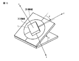
例えば、図13に示すように、傾斜板29上に設けられた回転板30の上にプロジェクタ1を設置することが考えられる。図13において、pは回転板30の回転角度(ヨー方向の角度)、qは傾斜板29の傾斜角度(ピッチ方向の角度)である。これらp及びqはそれぞれ(1)式のp及びqに相当する。この場合、ロール角は自動的につけられるので、ロール角を変更させるための制御及び駆動は不要となる。ただし図13において、p=q=0とした場合のプロジェクタ座標系のz軸がスクリーンを垂直に貫くようにスクリーンは設置されているものとする。
For example, as shown in FIG. 13, it is conceivable to install the projector 1 on the
つまり、この図13のプロジェクタ座標系は、最初に水平角度変更、次に垂直角度変更、最後にロール角変更を行った後のプロジェクタ座標系である図8(D)と等価である。すなわち、図13においてp≒25.7°、q≒33.7°のときのプロジェクタ座標系の3軸のそれぞれの向きが、図8においてh=v=30°、r≒16.1°のときのプロジェクタ座標系の3軸のそれぞれの向きと同じになる。 That is, the projector coordinate system of FIG. 13 is equivalent to FIG. 8D, which is the projector coordinate system after first changing the horizontal angle, then changing the vertical angle, and finally changing the roll angle. That is, the orientations of the three axes of the projector coordinate system when p≈25.7 ° and q≈33.7 ° in FIG. 13 are h = v = 30 ° and r≈16.1 ° in FIG. It becomes the same as each direction of the three axes of the projector coordinate system.
従って、本変形例2では、センサ等により直接的にp及びqを検出でき、容易に歪み補正処理パラメータを決定することが可能となる。 Therefore, in the second modification, p and q can be directly detected by a sensor or the like, and the distortion correction processing parameter can be easily determined.
また、プロジェクタ1の設計を変えることなくロール角の変更を行うことができるようになる。 In addition, the roll angle can be changed without changing the design of the projector 1.
以上、実施形態を用いて本発明を説明したが、本発明は前記実施形態そのままに限定されるものではなく、実施段階ではその要旨を逸脱しない範囲で構成要素を変形して具体化できる。 As described above, the present invention has been described using the embodiment. However, the present invention is not limited to the above-described embodiment as it is, and can be embodied by modifying constituent elements without departing from the scope of the invention in the implementation stage.
例えば、ロール角変更機構としては、プロジェクタ1全体の姿勢を変更するのではなく、プロジェクタ内部の出力表示素子を、光軸を中心に電気的に回転させる回転機構等、様々な手法を採り得る。このように、出力表示素子を、光軸を中心に回転させる回転機構をを用いて投影画像のロール角を変更するようにすることにより、プロジェクタ1の筐体内部でロール角の変更を行うことができる。なお、上述の回転機構等の構成によれば、ロール角変更の際に光軸位置が変わらないようにすることができる。 For example, as the roll angle changing mechanism, various methods such as a rotating mechanism for electrically rotating the output display element inside the projector around the optical axis can be adopted instead of changing the attitude of the entire projector 1. As described above, the roll angle of the projection image is changed inside the housing of the projector 1 by changing the roll angle of the projection image by using the rotation mechanism that rotates the output display element around the optical axis. Can do. In addition, according to the structure of the above-mentioned rotation mechanism etc., when changing a roll angle, it can prevent an optical axis position from changing.
また、図6や図13に示したような構成でロール角変更を変更させる場合も、光軸位置が変わらないようにすること望ましい。 Also, when the roll angle change is changed with the configuration shown in FIGS. 6 and 13, it is desirable that the optical axis position does not change.
図6のような構成でロール角変更を変更させる場合、例えば、左右の脚の一方の脚を伸ばす場合、他方の脚を左右方向の光軸位置に応じて、縮むようにすると、光軸位置が変わらないようにすることができる。 When changing the roll angle change in the configuration as shown in FIG. 6, for example, when extending one leg of the left and right legs, if the other leg is contracted according to the optical axis position in the left and right direction, the optical axis position is It can be kept unchanged.
しかし、ロール角変更の際に光軸位置が変わらないようにすることは必須ではない。 However, it is not essential that the optical axis position does not change when the roll angle is changed.
なお、それらロール角変更機構を併用できるような構成としてもよい。 In addition, it is good also as a structure which can use these roll angle change mechanisms together.
また、プロジェクタ1とスクリーン2との相対的角度の取得法に関しても、姿勢センサ23を用いずに、既知の多点測距手法、すなわち、スクリーン2までの複数の点(一直線上にない3点以上)までの距離を測定することにより、相対角度を取得することができる。この距離の測定法については、超音波、赤外線やレーザ光を用いるもの等、公知のどのような技術を用いても良い。このように測距手段で測定された測定結果に基づいてスクリーン2との相対角度を取得するようにすることで、適切に相対角度を取得することができる。さらに別の相対的角度の取得法として、テストチャートを投影し、それを撮像した画像データに基づいて取得したり、ユーザが測定して操作部22から入力したり、等々、様々な手法が採り得る。
In addition, regarding the method of obtaining the relative angle between the projector 1 and the
また、(1)式(及び(2)式)は最適ロール角を求める式ではなく、ベターな解を簡易的に求めるための式であり、本発明はその他の算出式を用いても良いことは勿論である。 In addition, equation (1) (and equation (2)) is not an equation for obtaining the optimum roll angle, but an equation for simply obtaining a better solution, and the present invention may use other calculation equations. Of course.
また、最適なロール角を求める場合は、スクリーン2との相対的な角度毎に最適なロール角を事前にあるいは逐次、総当たり法(例えば、制御可能な範囲で、0.5度刻みで画素利用率最大な角度を探索する方法)で求めることができる。このように、変更すべきロール角を探索し、決定して変更するようにすれば、最適なロール角を決定することができる。そしてさらに、そのように事前に調べた値を、例えば図14に示すようなルックアップテーブルとしてプログラムメモリ21に記憶しておくことで、該ルックアップテーブルを参照して、ロール角を決定することも可能である。このように、相対角度毎に変更すべきロール角を記憶しておき、この記憶した情報を参照して、変更すべきロール角を決定して変更することにより、迅速に最適なロール角を決定することができるようになる。
When obtaining the optimum roll angle, the optimum roll angle for each relative angle with the
なお、画像出力装置は、投影装置との通信機能と出力画素数の変更機能とを備えるものであれば、PCに限定されるものでは無い。 Note that the image output device is not limited to a PC as long as it has a communication function with the projection device and a function of changing the number of output pixels.
また、前記実施形態に開示されている複数の構成要素の適宜な組み合わせにより、種々の発明を形成できる。例えば、実施形態に示される全構成要素から幾つかの構成要素を削除しても、発明が解決しようとする課題の欄で述べられた課題が解決でき、かつ、発明の効果が得られる場合には、この構成要素が削除された構成も発明として抽出され得る。さらに、異なる実施形態にわたる構成要素を適宜組み合わせてもよい。 Various inventions can be formed by appropriately combining a plurality of constituent elements disclosed in the embodiment. For example, even if some constituent elements are deleted from all the constituent elements shown in the embodiment, the problem described in the column of problems to be solved by the invention can be solved and the effect of the invention can be obtained. The configuration in which this component is deleted can also be extracted as an invention. Furthermore, constituent elements over different embodiments may be appropriately combined.
以下に、本願出願の当初の特許請求の範囲に記載された発明を付記する。
[1]
画像出力装置より出力される画像信号を入力して被投影体に投影する投影装置であって、
当該投影装置と前記被投影体との相対角度を取得する取得手段と、
取得された前記相対角度に基づいて、前記画像出力装置に推奨する出力画素数を算出する推奨画素数算出手段と、
算出された前記出力画素数を前記画像出力装置に通知する通知手段と、
前記通知された前記出力画素数に応じて前記画像出力装置から出力された画像信号を、前記相対角度に基づいて、歪み補正して投影する歪み補正手段と、
を備えることを特徴とする投影装置。
Hereinafter, the invention described in the scope of claims of the present application will be appended.
[1]
A projection device that inputs an image signal output from an image output device and projects the image signal onto a projection target,
Obtaining means for obtaining a relative angle between the projection apparatus and the projection object;
Based on the acquired relative angle, a recommended pixel number calculating means for calculating the number of output pixels recommended for the image output device;
Notification means for notifying the image output device of the calculated number of output pixels;
Distortion correcting means for correcting and projecting the image signal output from the image output device in accordance with the notified number of output pixels, based on the relative angle, and correcting the distortion;
A projection apparatus comprising:
[2]
前記推奨画素数算出手段は、当該投影装置の出力表示素子の画素利用率を向上させるような出力画素数を算出することを特徴とする[1]に記載の投影装置。
[2]
The projection apparatus according to [1], wherein the recommended pixel number calculation unit calculates the number of output pixels so as to improve a pixel utilization rate of an output display element of the projection apparatus.
[3]
前記推奨画素数算出手段は、当該投影装置の出力表示素子の横縦比と異なる出力画素数を算出することを特徴とする[1]又は[2]に記載の投影装置。
[3]
The projection apparatus according to [1] or [2], wherein the recommended pixel number calculation unit calculates the number of output pixels different from the aspect ratio of the output display element of the projection apparatus.
[4]
前記推奨画素数算出手段は、前記出力画素数の横縦比が所定の範囲になるような出力画素数を算出することを特徴とする[1]乃至[3]のうち何れか一に記載の投影装置。
[4]
The recommended pixel number calculating unit calculates the number of output pixels so that the aspect ratio of the number of output pixels falls within a predetermined range. [1] to [3] Projection device.
[5]
前記取得手段は、前記画像出力装置のデフォルトの出力画素数を更に取得し、
前記推奨画素数算出手段は、取得された前記デフォルトの出力画素数に近い出力画素数を算出することを特徴とする[1]乃至[4]のうち何れか一に記載の投影装置。
[5]
The acquisition means further acquires a default output pixel number of the image output device,
The projection apparatus according to any one of [1] to [4], wherein the recommended pixel number calculation unit calculates an output pixel number close to the acquired default output pixel number.
[6]
前記推奨画素数算出は、前記出力画素数の候補を複数算出することを特徴とする[1]乃至[5]のうち何れか一に記載の投影装置。
[6]
The projection apparatus according to any one of [1] to [5], wherein the calculation of the recommended number of pixels includes calculating a plurality of candidates for the number of output pixels.
[7]
投影画像がロールするようにロール角を変更するロール角変更手段を更に備え、
前記推奨画素数算出手段は、前記ロール角変更手段により変更されるロール角も更に考慮して、出力画素数を算出し、
前記歪み補正手段は、前記ロール角変更手段により変更されるロール角を考慮して、投影画像を前記被投影体で矩形画像となるように歪み補正して投影することを特徴とする[1]乃至[6]のうち何れか一に記載の投影装置。
[7]
Roll angle changing means for changing the roll angle so that the projected image rolls;
The recommended pixel number calculating means calculates the output pixel number further considering the roll angle changed by the roll angle changing means,
The distortion correction unit projects the projection image by correcting the distortion so that the projected image becomes a rectangular image in consideration of the roll angle changed by the roll angle changing unit [1]. Thru | or the projection apparatus as described in any one of [6].
[8]
前記取得手段は、当該投影装置の投影時の画角情報を更に取得し、
前記推奨画素数算出手段は、取得された前記画角情報に更に基づいて、前記出力画素数を算出することを特徴とする[1]乃至[7]のうち何れか一に記載の投影装置。
[8]
The acquisition means further acquires angle-of-view information at the time of projection of the projection apparatus,
The projection apparatus according to any one of [1] to [7], wherein the recommended pixel number calculation unit calculates the output pixel number based further on the acquired angle-of-view information.
[9]
前記取得手段は、
前記被投影体までの複数の点までの距離を測定する測距手段を含み、
前記測距手段で測定された測定結果に基づいて、前記相対角度を取得することを特徴とする[1]乃至[8]のうち何れか一に記載の投影装置。
[9]
The acquisition means includes
Ranging means for measuring distances to a plurality of points to the projection object;
The projection apparatus according to any one of [1] to [8], wherein the relative angle is acquired based on a measurement result measured by the distance measuring unit.
[10]
当該投影装置の姿勢を検出する姿勢検出手段を更に備え、
前記取得手段は、前記姿勢検出手段で検出された検出結果に基づいて、前記相対角度を取得することを特徴とする[1]乃至[9]のうち何れか一に記載の投影装置。
[10]
It further comprises posture detecting means for detecting the posture of the projection device,
The projection apparatus according to any one of [1] to [9], wherein the acquisition unit acquires the relative angle based on a detection result detected by the posture detection unit.
[11]
出力した画像信号を被投影体に投影する投影装置と協働する画像出力装置であって、
前記投影装置と前記被投影体との相対角度及び投影時の画角情報を取得する取得手段と、
取得された前記相対角度及び前記画角情報に基づいて、歪み補正する際に出力する画像信号の推奨する出力画素数を算出する推奨画素数算出手段と、
前記相対角度及び前記画角情報に基づいて、出力する画像信号を歪み補正する歪み補正手段と、
算出した推奨する出力画素数で、歪み補正された前記画像信号を前記投影装置に出力する出力手段と、
を備えることを特徴とする画像出力装置。
[11]
An image output device that cooperates with a projection device that projects an output image signal onto a projection object,
An acquisition means for acquiring a relative angle between the projection apparatus and the projection object and angle of view information at the time of projection;
Based on the acquired relative angle and the angle-of-view information, a recommended pixel number calculating unit that calculates a recommended number of output pixels of an image signal output when correcting distortion;
Distortion correction means for correcting distortion of an output image signal based on the relative angle and the angle of view information;
An output means for outputting the image signal corrected for distortion to the projection device with the calculated recommended number of output pixels;
An image output apparatus comprising:
[12]
前記歪み補正手段は、前記投影装置に前記相対角度及び前記画角情報に基づいて、前記投影装置の出力表示素子の画素利用率を向上させるように歪み補正することを特徴とする[11]に記載の画像出力装置。
[12]
[11], wherein the distortion correction means corrects the distortion to improve the pixel utilization rate of the output display element of the projection device based on the relative angle and the angle-of-view information. The image output device described.
[13]
前記取得手段は、前記投影装置の出力表示素子の画素数を更に取得し、
前記推奨画素数算出手段は、取得された前記画素数に更に基づいて、前記推奨する出力画素数を算出することを特徴とする[11]又は[12]に記載の画像出力装置。
[13]
The acquisition means further acquires the number of pixels of the output display element of the projection device,
The image output apparatus according to [11] or [12], wherein the recommended pixel number calculation unit calculates the recommended output pixel number based further on the acquired pixel number.
[14]
前記歪み補正手段は、前記投影装置にロール角調整をさせるように画像信号を歪み補正し、
前記ロール角の調整量を前記投影装置に通知する通知手段を更に備えることを特徴とする[11]乃至[13]のうち何れか一に記載の画像出力装置。
[14]
The distortion correction means corrects the distortion of the image signal so that the projection apparatus adjusts the roll angle,
The image output apparatus according to any one of [11] to [13], further comprising notification means for notifying the projection apparatus of an adjustment amount of the roll angle.
[15]
画像出力装置より出力される画像信号を入力して被投影体に投影する投影装置における投影方法であって、
当該投影装置と前記被投影体との相対角度を取得する相対角度取得工程と、
前記相対角度取得工程により取得された前記相対角度に基づいて、前記画像出力装置に推奨する出力画素数を算出する推奨画素数算出工程と、
前記推奨画素数算出工程により算出された前記出力画素数を前記画像出力装置に通知する通知工程と、
前記通知された前記出力画素数に応じて前記画像出力装置から出力された画像信号を、前記相対角度取得工程により取得された前記相対角度に基づいて、歪み補正して投影する歪み補正工程と、
を備えることを特徴とする投影方法。
[15]
A projection method in a projection apparatus for inputting an image signal output from an image output apparatus and projecting it on a projection object,
A relative angle acquisition step of acquiring a relative angle between the projection apparatus and the projection target;
Based on the relative angle acquired by the relative angle acquisition step, a recommended pixel number calculation step of calculating the number of output pixels recommended for the image output device;
A notification step of notifying the image output device of the number of output pixels calculated by the recommended pixel number calculation step;
A distortion correction step of correcting and projecting the image signal output from the image output device according to the notified number of output pixels based on the relative angle acquired by the relative angle acquisition step;
A projection method comprising:
[16]
画像出力装置より出力される画像信号を入力して被投影体に投影する投影装置におけるコンピュータに、
当該投影装置と前記被投影体との相対角度を取得することと、
取得された前記相対角度に基づいて、前記画像出力装置に推奨する出力画素数を算出することと、
算出された前記出力画素数を前記画像出力装置に通知することと、
前記通知された前記出力画素数に応じて前記画像出力装置から出力された画像信号を、前記相対角度に基づいて、歪み補正して投影することと、
を実行させるための投影プログラム。
[16]
To a computer in a projection apparatus that inputs an image signal output from the image output apparatus and projects the image signal on a projection object,
Obtaining a relative angle between the projection apparatus and the projection object;
Calculating the recommended number of output pixels for the image output device based on the acquired relative angle;
Notifying the image output device of the calculated number of output pixels;
Projecting the image signal output from the image output device according to the notified number of output pixels after correcting the distortion based on the relative angle;
Projection program to execute.
1…プロジェクタ、 2…スクリーン、 3…水平ベース、 4…パーソナルコンピュータ(PC)、 11…入出力コネクタ部、 12…入出力インターフェース、 13…画像変換部、 14…投影処理部、 15…マイクロミラー素子、 16…光源部、 17…ミラー、 18…投影レンズ、 19…CPU、 20…メインメモリ、 21…プログラムメモリ、 22…操作部、 23…姿勢センサ、 24…音声処理部、 25…スピーカ、 26…レンズ調整部、 27…姿勢調整部、 28…電動脚部、 28A…脚、 29…傾斜板、 30…回転板。 DESCRIPTION OF SYMBOLS 1 ... Projector, 2 ... Screen, 3 ... Horizontal base, 4 ... Personal computer (PC), 11 ... Input / output connector part, 12 ... Input / output interface, 13 ... Image conversion part, 14 ... Projection processing part, 15 ... Micromirror Element: 16 ... Light source unit, 17 ... Mirror, 18 ... Projection lens, 19 ... CPU, 20 ... Main memory, 21 ... Program memory, 22 ... Operation unit, 23 ... Attitude sensor, 24 ... Audio processing unit, 25 ... Speaker, 26: Lens adjusting unit, 27: Posture adjusting unit, 28 ... Electric leg unit, 28A ... Leg, 29 ... Inclined plate, 30 ... Rotating plate.
Claims (16)
当該投影装置と前記被投影体との相対角度を取得する取得手段と、
取得された前記相対角度に基づいて、前記画像出力装置に推奨する出力画素数を算出する推奨画素数算出手段と、
算出された前記出力画素数を前記画像出力装置に通知する通知手段と、
前記通知された前記出力画素数に応じて前記画像出力装置から出力された画像信号を、前記相対角度に基づいて、歪み補正して投影する歪み補正手段と、
を備えることを特徴とする投影装置。 A projection device that inputs an image signal output from an image output device and projects the image signal onto a projection target,
Obtaining means for obtaining a relative angle between the projection apparatus and the projection object;
Based on the acquired relative angle, a recommended pixel number calculating means for calculating the number of output pixels recommended for the image output device;
Notification means for notifying the image output device of the calculated number of output pixels;
Distortion correcting means for correcting and projecting the image signal output from the image output device in accordance with the notified number of output pixels, based on the relative angle, and correcting the distortion;
A projection apparatus comprising:
前記推奨画素数算出手段は、取得された前記デフォルトの出力画素数に近い出力画素数を算出することを特徴とする請求項1乃至請求項4のうち何れか一に記載の投影装置。 The acquisition means further acquires a default output pixel number of the image output device,
5. The projection apparatus according to claim 1, wherein the recommended pixel number calculating unit calculates an output pixel number close to the acquired default output pixel number. 6.
前記推奨画素数算出手段は、前記ロール角変更手段により変更されるロール角も更に考慮して、出力画素数を算出し、
前記歪み補正手段は、前記ロール角変更手段により変更されるロール角を考慮して、投影画像を前記被投影体で矩形画像となるように歪み補正して投影することを特徴とする請求項1乃至請求項6のうち何れか一に記載の投影装置。 Roll angle changing means for changing the roll angle so that the projected image rolls;
The recommended pixel number calculating means calculates the output pixel number further considering the roll angle changed by the roll angle changing means,
2. The distortion correcting unit projects the projected image after correcting the distortion so that the projected image becomes a rectangular image in consideration of the roll angle changed by the roll angle changing unit. The projection device according to any one of claims 6 to 6.
前記推奨画素数算出手段は、取得された前記画角情報に更に基づいて、前記出力画素数を算出することを特徴とする請求項1乃至請求項7のうち何れか一に記載の投影装置。 The acquisition means further acquires angle-of-view information at the time of projection of the projection apparatus,
The projection apparatus according to claim 1, wherein the recommended pixel number calculation unit calculates the output pixel number based further on the acquired angle-of-view information.
前記被投影体までの複数の点までの距離を測定する測距手段を含み、
前記測距手段で測定された測定結果に基づいて、前記相対角度を取得することを特徴とする請求項1乃至請求項8のうち何れか一に記載の投影装置。 The acquisition means includes
Ranging means for measuring distances to a plurality of points to the projection object;
The projection apparatus according to claim 1, wherein the relative angle is acquired based on a measurement result measured by the distance measuring unit.
前記取得手段は、前記姿勢検出手段で検出された検出結果に基づいて、前記相対角度を取得することを特徴とする請求項1乃至請求項9のうち何れか一に記載の投影装置。 It further comprises posture detecting means for detecting the posture of the projection device,
The projection apparatus according to claim 1, wherein the acquisition unit acquires the relative angle based on a detection result detected by the posture detection unit.
前記投影装置と前記被投影体との相対角度及び投影時の画角情報を取得する取得手段と、
取得された前記相対角度及び前記画角情報に基づいて、歪み補正する際に出力する画像信号の推奨する出力画素数を算出する推奨画素数算出手段と、
前記相対角度及び前記画角情報に基づいて、出力する画像信号を歪み補正する歪み補正手段と、
算出した推奨する出力画素数で、歪み補正された前記画像信号を前記投影装置に出力する出力手段と、
を備えることを特徴とする画像出力装置。 An image output device that cooperates with a projection device that projects an output image signal onto a projection object,
An acquisition means for acquiring a relative angle between the projection apparatus and the projection object and angle of view information at the time of projection;
Based on the acquired relative angle and the angle-of-view information, a recommended pixel number calculating unit that calculates a recommended number of output pixels of an image signal output when correcting distortion;
Distortion correction means for correcting distortion of an output image signal based on the relative angle and the angle of view information;
An output means for outputting the image signal corrected for distortion to the projection device with the calculated recommended number of output pixels;
An image output apparatus comprising:
前記推奨画素数算出手段は、取得された前記画素数に更に基づいて、前記推奨する出力画素数を算出することを特徴とする請求項11又は請求項12に記載の画像出力装置。 The acquisition means further acquires the number of pixels of the output display element of the projection device,
The image output apparatus according to claim 11 or 12, wherein the recommended pixel number calculating unit calculates the recommended output pixel number further based on the acquired pixel number.
前記ロール角の調整量を前記投影装置に通知する通知手段を更に備えることを特徴とする請求項11乃至請求項13のうち何れか一に記載の画像出力装置。 The distortion correction means corrects the distortion of the image signal so that the projection apparatus adjusts the roll angle,
The image output apparatus according to claim 11, further comprising a notification unit that notifies the projection apparatus of an adjustment amount of the roll angle.
当該投影装置と前記被投影体との相対角度を取得する相対角度取得工程と、
前記相対角度取得工程により取得された前記相対角度に基づいて、前記画像出力装置に推奨する出力画素数を算出する推奨画素数算出工程と、
前記推奨画素数算出工程により算出された前記出力画素数を前記画像出力装置に通知する通知工程と、
前記通知された前記出力画素数に応じて前記画像出力装置から出力された画像信号を、前記相対角度取得工程により取得された前記相対角度に基づいて、歪み補正して投影する歪み補正工程と、
を備えることを特徴とする投影方法。 A projection method in a projection apparatus for inputting an image signal output from an image output apparatus and projecting it on a projection object,
A relative angle acquisition step of acquiring a relative angle between the projection apparatus and the projection target;
Based on the relative angle acquired by the relative angle acquisition step, a recommended pixel number calculation step of calculating the number of output pixels recommended for the image output device;
A notification step of notifying the image output device of the number of output pixels calculated by the recommended pixel number calculation step;
A distortion correction step of correcting and projecting the image signal output from the image output device according to the notified number of output pixels based on the relative angle acquired by the relative angle acquisition step;
A projection method comprising:
当該投影装置と前記被投影体との相対角度を取得することと、
取得された前記相対角度に基づいて、前記画像出力装置に推奨する出力画素数を算出することと、
算出された前記出力画素数を前記画像出力装置に通知することと、
前記通知された前記出力画素数に応じて前記画像出力装置から出力された画像信号を、前記相対角度に基づいて、歪み補正して投影することと、
を実行させるための投影プログラム。 To a computer in a projection apparatus that inputs an image signal output from the image output apparatus and projects the image signal on a projection object,
Obtaining a relative angle between the projection apparatus and the projection object;
Calculating the recommended number of output pixels for the image output device based on the acquired relative angle;
Notifying the image output device of the calculated number of output pixels;
Projecting the image signal output from the image output device according to the notified number of output pixels after correcting the distortion based on the relative angle;
Projection program to execute.
Priority Applications (1)
| Application Number | Priority Date | Filing Date | Title |
|---|---|---|---|
| JP2013060735A JP6197322B2 (en) | 2013-03-22 | 2013-03-22 | Projection device, image output device, projection method, and projection program |
Applications Claiming Priority (1)
| Application Number | Priority Date | Filing Date | Title |
|---|---|---|---|
| JP2013060735A JP6197322B2 (en) | 2013-03-22 | 2013-03-22 | Projection device, image output device, projection method, and projection program |
Publications (2)
| Publication Number | Publication Date |
|---|---|
| JP2014187530A true JP2014187530A (en) | 2014-10-02 |
| JP6197322B2 JP6197322B2 (en) | 2017-09-20 |
Family
ID=51834647
Family Applications (1)
| Application Number | Title | Priority Date | Filing Date |
|---|---|---|---|
| JP2013060735A Active JP6197322B2 (en) | 2013-03-22 | 2013-03-22 | Projection device, image output device, projection method, and projection program |
Country Status (1)
| Country | Link |
|---|---|
| JP (1) | JP6197322B2 (en) |
Cited By (2)
| Publication number | Priority date | Publication date | Assignee | Title |
|---|---|---|---|---|
| WO2023113201A1 (en) * | 2021-12-17 | 2023-06-22 | 삼성전자주식회사 | Electronic device and control method therefor |
| WO2024029991A1 (en) * | 2022-08-05 | 2024-02-08 | 삼성전자 주식회사 | Electronic device and operating method thereof |
Families Citing this family (1)
| Publication number | Priority date | Publication date | Assignee | Title |
|---|---|---|---|---|
| CN113292703B (en) * | 2021-05-28 | 2022-06-03 | 南京工业大学 | Phosphorus-free full-bio-based flame-retardant epoxy resin with excellent thermal and mechanical properties and green preparation method thereof |
Citations (5)
| Publication number | Priority date | Publication date | Assignee | Title |
|---|---|---|---|---|
| JP2004032484A (en) * | 2002-06-27 | 2004-01-29 | Sony Corp | Projection type image display and method for converting image |
| JP2005150818A (en) * | 2003-11-11 | 2005-06-09 | Nec Viewtechnology Ltd | Projector system provided with computer including distortion correction means |
| JP2006005549A (en) * | 2004-06-16 | 2006-01-05 | Sony Corp | Image projector, image processor and processing method |
| JP2006313259A (en) * | 2005-05-09 | 2006-11-16 | Seiko Epson Corp | Supply of image to projector |
| JP2009005148A (en) * | 2007-06-22 | 2009-01-08 | Seiko Epson Corp | Image processing unit, and projector |
-
2013
- 2013-03-22 JP JP2013060735A patent/JP6197322B2/en active Active
Patent Citations (5)
| Publication number | Priority date | Publication date | Assignee | Title |
|---|---|---|---|---|
| JP2004032484A (en) * | 2002-06-27 | 2004-01-29 | Sony Corp | Projection type image display and method for converting image |
| JP2005150818A (en) * | 2003-11-11 | 2005-06-09 | Nec Viewtechnology Ltd | Projector system provided with computer including distortion correction means |
| JP2006005549A (en) * | 2004-06-16 | 2006-01-05 | Sony Corp | Image projector, image processor and processing method |
| JP2006313259A (en) * | 2005-05-09 | 2006-11-16 | Seiko Epson Corp | Supply of image to projector |
| JP2009005148A (en) * | 2007-06-22 | 2009-01-08 | Seiko Epson Corp | Image processing unit, and projector |
Cited By (2)
| Publication number | Priority date | Publication date | Assignee | Title |
|---|---|---|---|---|
| WO2023113201A1 (en) * | 2021-12-17 | 2023-06-22 | 삼성전자주식회사 | Electronic device and control method therefor |
| WO2024029991A1 (en) * | 2022-08-05 | 2024-02-08 | 삼성전자 주식회사 | Electronic device and operating method thereof |
Also Published As
| Publication number | Publication date |
|---|---|
| JP6197322B2 (en) | 2017-09-20 |
Similar Documents
| Publication | Publication Date | Title |
|---|---|---|
| JP6244638B2 (en) | Projection apparatus, projection method, and projection program | |
| JP6201359B2 (en) | Projection system, projection method, and projection program | |
| US9723281B2 (en) | Projection apparatus for increasing pixel usage of an adjusted projection area, and projection method and program medium for the same | |
| US9514716B2 (en) | Projection apparatus, projection control apparatus, projection system, and projection state adjustment method | |
| US10979682B2 (en) | Projector and method for controlling projector | |
| US11006066B2 (en) | Projector and method for controlling projector | |
| JP2020112711A (en) | Method for controlling projector, projector, and projection system | |
| JP2005033703A (en) | System and method for processing image, projector, program, and information storage medium | |
| JP6197322B2 (en) | Projection device, image output device, projection method, and projection program | |
| JP6590008B2 (en) | Projection apparatus, projection method, and projection program | |
| JP6232695B2 (en) | Projection apparatus, projection control apparatus, projection system, and projection state adjustment method | |
| JP6127443B2 (en) | Projection apparatus and projection state adjustment method | |
| JP2012199772A (en) | Projector and projector installation method | |
| JP6926464B2 (en) | Projector, projection method and program | |
| JP2013083985A (en) | Projection device, projection method, and program | |
| JP2006235073A (en) | Projector, projection method and program | |
| JP2014010609A (en) | Projection device, pointer device and projection system | |
| JP6286978B2 (en) | Projection apparatus, projection method, and projection program | |
| JP5630799B2 (en) | Projection apparatus, projection method, and program | |
| JP2010283449A (en) | Projection system, projector, voice control method, and program | |
| JP2017152765A (en) | Projector and projector control method | |
| JP4511433B2 (en) | Image processing system, projector, portable device, and image processing method | |
| JP2017169204A (en) | Projection apparatus and projection state adjustment method | |
| JP2011252972A (en) | Projection device, projection method and program | |
| JP2009069661A (en) | Projection device, projection method, and program |
Legal Events
| Date | Code | Title | Description |
|---|---|---|---|
| A621 | Written request for application examination |
Free format text: JAPANESE INTERMEDIATE CODE: A621 Effective date: 20160229 |
|
| A977 | Report on retrieval |
Free format text: JAPANESE INTERMEDIATE CODE: A971007 Effective date: 20161209 |
|
| A131 | Notification of reasons for refusal |
Free format text: JAPANESE INTERMEDIATE CODE: A131 Effective date: 20161220 |
|
| A521 | Written amendment |
Free format text: JAPANESE INTERMEDIATE CODE: A523 Effective date: 20170210 |
|
| TRDD | Decision of grant or rejection written | ||
| A01 | Written decision to grant a patent or to grant a registration (utility model) |
Free format text: JAPANESE INTERMEDIATE CODE: A01 Effective date: 20170725 |
|
| A61 | First payment of annual fees (during grant procedure) |
Free format text: JAPANESE INTERMEDIATE CODE: A61 Effective date: 20170807 |
|
| R150 | Certificate of patent or registration of utility model |
Ref document number: 6197322 Country of ref document: JP Free format text: JAPANESE INTERMEDIATE CODE: R150 |