JP2014183647A - Coil, rotary electric machine and manufacturing method of rotary electric machine - Google Patents
Coil, rotary electric machine and manufacturing method of rotary electric machine Download PDFInfo
- Publication number
- JP2014183647A JP2014183647A JP2013056299A JP2013056299A JP2014183647A JP 2014183647 A JP2014183647 A JP 2014183647A JP 2013056299 A JP2013056299 A JP 2013056299A JP 2013056299 A JP2013056299 A JP 2013056299A JP 2014183647 A JP2014183647 A JP 2014183647A
- Authority
- JP
- Japan
- Prior art keywords
- coil
- stator core
- axial direction
- inner peripheral
- peripheral side
- Prior art date
- Legal status (The legal status is an assumption and is not a legal conclusion. Google has not performed a legal analysis and makes no representation as to the accuracy of the status listed.)
- Granted
Links
Images


Classifications
-
- H—ELECTRICITY
- H02—GENERATION; CONVERSION OR DISTRIBUTION OF ELECTRIC POWER
- H02K—DYNAMO-ELECTRIC MACHINES
- H02K3/00—Details of windings
- H02K3/04—Windings characterised by the conductor shape, form or construction, e.g. with bar conductors
- H02K3/12—Windings characterised by the conductor shape, form or construction, e.g. with bar conductors arranged in slots
-
- Y—GENERAL TAGGING OF NEW TECHNOLOGICAL DEVELOPMENTS; GENERAL TAGGING OF CROSS-SECTIONAL TECHNOLOGIES SPANNING OVER SEVERAL SECTIONS OF THE IPC; TECHNICAL SUBJECTS COVERED BY FORMER USPC CROSS-REFERENCE ART COLLECTIONS [XRACs] AND DIGESTS
- Y10—TECHNICAL SUBJECTS COVERED BY FORMER USPC
- Y10T—TECHNICAL SUBJECTS COVERED BY FORMER US CLASSIFICATION
- Y10T29/00—Metal working
- Y10T29/49—Method of mechanical manufacture
- Y10T29/49002—Electrical device making
- Y10T29/49009—Dynamoelectric machine
Landscapes
- Engineering & Computer Science (AREA)
- Power Engineering (AREA)
- Manufacture Of Motors, Generators (AREA)
- Windings For Motors And Generators (AREA)
- Manufacturing & Machinery (AREA)
Abstract
Description
この発明は、コイル、回転電機および回転電機の製造方法に関する。 The present invention relates to a coil, a rotating electrical machine, and a method for manufacturing the rotating electrical machine.
従来、ステータコアの軸方向の一方側のコイルエンドにおいて、ステータコアの内周側に折り曲げられたコイルを備える回転電機が知られている(たとえば、特許文献1参照)。上記特許文献1では、予めステータコアの内周側に折り曲げられた形状を有するように形成されたコイルを、ステータコアのスロットに装着するように構成されている。なお、上記特許文献1では、スロットは、軸方向から見て、略長方形形状(スロットの内周側の部分の周方向の幅と、その他の部分の周方向の幅とが略同じ形状)を有するように構成されている。
2. Description of the Related Art Conventionally, a rotating electrical machine is known that includes a coil bent on the inner peripheral side of a stator core at one coil end in the axial direction of the stator core (see, for example, Patent Document 1). In the above-mentioned
また、従来、スロットとしては、軸方向から見て、スロットの内周側の部分の周方向の幅が、その他の部分の周方向の幅(コイルの幅)に比べて小さいスロット(コイルのはみ出し防止部が設けられたスロット)が知られている。すなわち、スロットの内周側の開口をコイルの幅よりも小さくし、そこにコイル飛び出し防止用くさび(ウェッジ)を設けることにより、コイルのステータコアの内周側へのはみ出しを防止している。 Conventionally, as a slot, a slot (coil protrusion) in which the circumferential width of the inner circumferential portion of the slot is smaller than the circumferential width (coil width) of the other portion when viewed from the axial direction. A slot provided with a prevention part is known. That is, the opening on the inner peripheral side of the slot is made smaller than the width of the coil, and a wedge (wedge) for preventing the coil jumping out is provided there, thereby preventing the coil from protruding to the inner peripheral side of the stator core.
しかしながら、従来のコイルのはみ出し防止部が設けられたスロットに、上記特許文献1に記載のような予めステータコアの内周側に折り曲げられた形状を有するように形成されたコイルを、たとえばコイルをスロット内周側から挿入する場合、コイルはスロット内周側の開口部より細い線が必要となるため、1本の線を細い線の束にする必要があり、コイル挿入が困難になるという問題点がある。また、内周側に折り曲げられた側からステータコアの軸方向に沿って挿入する場合、スロットの開口幅がコイルの幅よりも小さいため、コイルのステータコアの内周側に折り曲げられた部分がスロットの開口部分に当接して、コイルをスロットに挿入できない場合があるという問題点がある。また、ティース先端部に溝を設け、コイル飛び出し防止用くさび(ウェッジ)を挿入する場合、溝によりティース幅が細くなり磁気回路上損失が増大するという問題点がある。
However, a conventional coil that has a shape that is bent in advance on the inner peripheral side of the stator core as described in
この発明は、上記のような課題を解決するためになされたものであり、この発明の1つの目的は、軸方向の一方側のコイルエンドにおいてステータコアの内周側に折り曲げられたコイル本体を、容易に、軸方向に沿ってスロットに挿入することが可能なコイル、回転電機および回転電機の製造方法を提供することである。 The present invention has been made to solve the above-described problems, and one object of the present invention is to provide a coil body bent toward the inner peripheral side of the stator core at one end of the coil in the axial direction. It is an object of the present invention to provide a coil, a rotating electrical machine, and a manufacturing method of the rotating electrical machine that can be easily inserted into a slot along the axial direction.
第1の局面によるコイルは、コイルがステータコアの内周側にはみ出すのを防止するためのはみ出し防止部がティースに設けられているステータコアの軸方向の一方側のコイルエンド側から、軸方向に沿ってステータコアのスロットに挿入可能に構成されているコイルであって、コイルは、軸方向の一方側のコイルエンドにおいて、ステータコアの内周側に折り曲げられたコイル本体と、コイル本体のステータコアの内周側に折り曲げられた部分に設けられ、ステータコアの内周側に折り曲げられた軸方向の一方側のコイルエンド側からコイル本体を軸方向に沿ってステータコアのスロットに挿入する際に、ティースのはみ出し防止部を逃がすための逃がし部とを備える。 In the coil according to the first aspect, the protrusion preventing portion for preventing the coil from protruding to the inner peripheral side of the stator core is provided along the axial direction from the coil end side on the one axial side of the stator core provided on the teeth. The coil is configured to be insertable into a slot of the stator core, and the coil includes a coil body bent toward the inner peripheral side of the stator core at the coil end on one axial side, and an inner periphery of the stator core of the coil main body. To prevent protrusion of teeth when inserting the coil body into the slot of the stator core along the axial direction from one coil end side of the axial direction, which is provided on the side bent portion and bent toward the inner peripheral side of the stator core A relief part for escaping the part.
第1の局面によるコイルでは、上記のように、コイル本体のステータコアの内周側に折り曲げられた部分に、ステータコアの内周側に折り曲げられた軸方向の一方側のコイルエンド側からコイル本体を軸方向に沿ってステータコアのスロットに挿入する際に、ティースのはみ出し防止部を逃がすための逃がし部を設けることによって、コイル本体のスロットへの挿入の妨げとなるはみ出し防止部を逃がし部により逃がすことができる。その結果、軸方向の一方側のコイルエンドにおいてステータコアの内周側に折り曲げられたコイル本体を、容易に、軸方向に沿ってスロットに挿入することができる。 In the coil according to the first aspect, as described above, the coil body is attached to the portion of the coil body that is bent toward the inner peripheral side of the stator core from the one coil end side in the axial direction that is bent toward the inner peripheral side of the stator core. When inserting into the slot of the stator core along the axial direction, by providing a relief part to escape the tooth protrusion prevention part, the protrusion prevention part that prevents the coil body from being inserted into the slot is released by the relief part. Can do. As a result, the coil body bent toward the inner peripheral side of the stator core at the coil end on one axial side can be easily inserted into the slot along the axial direction.
第2の局面による回転電機は、コイルがステータコアの内周側にはみ出すのを防止するためのはみ出し防止部がティースに設けられているステータコアと、ステータコアの軸方向の一方側のコイルエンド側から、軸方向に沿ってステータコアのスロットに挿入可能に構成されているコイルとを備え、コイルは、軸方向の一方側のコイルエンドにおいて、ステータコアの内周側に折り曲げられたコイル本体と、コイル本体のステータコアの内周側に折り曲げられた部分に設けられ、ステータコアの内周側に折り曲げられた軸方向の一方側のコイルエンド側からコイル本体を軸方向に沿ってステータコアのスロットに挿入する際に、ティースのはみ出し防止部を逃がすための逃がし部とを含む。 In the rotating electrical machine according to the second aspect, from the stator core in which the protrusion preventing portion for preventing the coil from protruding to the inner peripheral side of the stator core is provided on the teeth, and from the coil end side on one side in the axial direction of the stator core, A coil configured to be insertable into a slot of the stator core along the axial direction, the coil being bent at the inner peripheral side of the stator core at a coil end on one axial side, When the coil body is inserted into the slot of the stator core along the axial direction from the coil end side on one side of the axial direction which is provided on the inner circumferential side of the stator core and is folded toward the inner circumferential side of the stator core, And a relief portion for escaping the protrusion prevention portion of the teeth.
第2の局面による回転電機では、上記のように、コイル本体のステータコアの内周側に折り曲げられた部分に、ステータコアの内周側に折り曲げられた軸方向の一方側のコイルエンド側からコイル本体を軸方向に沿ってステータコアのスロットに挿入する際に、ティースのはみ出し防止部を逃がすための逃がし部を設けることによって、コイル本体のスロットへの挿入の妨げとなるはみ出し防止部を逃がし部により逃がすことができる。その結果、軸方向の一方側のコイルエンドにおいてステータコアの内周側に折り曲げられたコイル本体を、容易に、軸方向に沿ってスロットに挿入することが可能な回転電機を提供することができる。 In the rotating electrical machine according to the second aspect, as described above, the coil body is connected to the portion of the coil body that is bent toward the inner peripheral side of the stator core from the coil end side on one axial side that is bent toward the inner peripheral side of the stator core. When the sleeve is inserted into the slot of the stator core along the axial direction, by providing a relief part to escape the tooth protrusion prevention part, the protrusion prevention part that prevents the coil body from being inserted into the slot is released by the relief part. be able to. As a result, it is possible to provide a rotating electrical machine that can easily insert a coil body that is bent toward the inner peripheral side of the stator core at one coil end in the axial direction into the slot along the axial direction.
第3の局面による回転電機の製造方法は、コイルがステータコアの内周側にはみ出すのを防止するためのはみ出し防止部がティースに設けられているステータコアを準備する工程と、軸方向の一方側のコイルエンドにおいて、ステータコアの内周側に折り曲げられたコイル本体と、コイル本体のステータコアの内周側に折り曲げられた部分に設けられ、ティースのはみ出し防止部を逃がすための逃がし部とを備えるコイルを準備する工程と、ティースのはみ出し防止部を逃がし部により逃がしながら、ステータコアの内周側に折り曲げられた軸方向の一方側のコイルエンド側からコイル本体を軸方向に沿ってステータコアのスロットに挿入する工程とを備える。 A method of manufacturing a rotating electrical machine according to a third aspect includes a step of preparing a stator core in which a protrusion preventing portion for preventing a coil from protruding to the inner peripheral side of the stator core is provided on the teeth, A coil comprising a coil body bent at the inner peripheral side of the stator core at the coil end, and a relief portion provided at a portion of the coil body that is bent toward the inner peripheral side of the stator core to escape the protrusion preventing portion of the teeth. The coil body is inserted into the slot of the stator core along the axial direction from the coil end side on one side of the axial direction bent to the inner peripheral side of the stator core, while the step of preparing and the tooth protrusion prevention portion are escaped by the escape portion. A process.
第3の局面による回転電機の製造方法では、上記のように、ティースのはみ出し防止部を逃がし部により逃がしながら、ステータコアの内周側に折り曲げられた軸方向の一方側のコイルエンド側からコイル本体を軸方向に沿ってステータコアのスロットに挿入する工程を備えることによって、コイル本体のスロットへの挿入の妨げとなるはみ出し防止部を逃がし部により逃がすことができる。その結果、軸方向の一方側のコイルエンドにおいてステータコアの内周側に折り曲げられたコイル本体を、容易に、軸方向に沿ってスロットに挿入することが可能な回転電機の製造方法を提供することができる。 In the method of manufacturing the rotating electrical machine according to the third aspect, as described above, the coil main body from the coil end side on one axial side bent to the inner peripheral side of the stator core while the tooth protrusion preventing portion is released by the escape portion. Is provided in the slot of the stator core along the axial direction, so that the protrusion preventing part that prevents the coil body from being inserted into the slot can be released by the escape part. As a result, it is possible to provide a method of manufacturing a rotating electrical machine in which a coil body bent toward the inner peripheral side of a stator core at one coil end in the axial direction can be easily inserted into a slot along the axial direction. Can do.
上記コイル、回転電機および回転電機の製造方法によれば、軸方向の一方側のコイルエンドにおいてステータコアの内周側に折り曲げられたコイル本体を、容易に、軸方向に沿ってスロットに挿入することができる。 According to the coil, the rotating electrical machine, and the method for manufacturing the rotating electrical machine, the coil body bent toward the inner peripheral side of the stator core at the coil end on one axial side can be easily inserted into the slot along the axial direction. Can do.
以下、実施形態を図面に基づいて説明する。 Hereinafter, embodiments will be described with reference to the drawings.
まず、図1〜図7を参照して、本実施形態による電動機100の構成について説明する。本実施形態では、回転電機の一例であるラジアル型の電動機100を説明する。
First, with reference to FIGS. 1-7, the structure of the
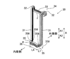
図1に示すように、電動機100は、固定部であるステータ1と、回転部であるロータ2(一点鎖線参照)とを備えている。ロータ2は、シャフト21(一点鎖線参照)と、ロータコア22(一点鎖線参照)と、図示しない複数の永久磁石とを含み、シャフト21を中心に回転可能となっている。
As shown in FIG. 1, the
ステータ1は、複数のスロット11を有するステータコア1aと、各スロットに装着された複数のコイル1bとを含んでいる。ステータコア1aは、円筒形状に形成され、内周側で半径方向Bの内側に延びる複数のティース12を有する。ティース12は、ステータコア1aの周方向Cに沿って等角度間隔で設けられており、このティース12の間の部分がスロット11である。
The
ここで、本実施形態では、図6に示すように、ステータコア1aのティース12には、コイル1bがステータコア1aの内周側にはみ出すのを防止するためのはみ出し防止部12aが設けられている。具体的には、はみ出し防止部12aは、軸方向から見て、ティース12の内周側の端部から、スロット11内に周方向に突出するように形成された凸部からなる。なお、はみ出し防止部12a(凸部)は、軸方向から見て、たとえば、略半円形状を有する。また、はみ出し防止部12aは、ティース12の周方向の一方側および他方側の両方の側端面からスロット11内に突出するように形成されている。これにより、スロット11は、軸方向から見て、スロット11の内周側の部分の周方向の幅W3が、その他の部分の周方向の幅W1(コイルの幅W1)に比べて小さいスロットになる。その結果、後述するコイル1bのコイル辺部(U相コイル30のコイル辺部31(図2参照)、V相コイル40のコイル辺部41(図3参照)、W相コイル50のコイル辺部51(図4参照))が、ステータコア1aの内周側にはみ出すのが、はみ出し防止部12aにより防止される。また、はみ出し防止部12aは、図9に示すように、スロット11の軸方向の一方端部側(A1方向側)から他方端部側(A2方向側)まで延びるように形成されている。
Here, in the present embodiment, as shown in FIG. 6, the
電動機100は、3相のコイルが分布巻の同心巻で各スロット11に装着された3相交流の回転電機である。たとえば、電動機100は、8極、48スロットを有し、毎極毎相スロット数qが、q=2(=48/(3×8))の回転電機からなる。複数のコイル1bは、3相交流の各相に対応して、U相コイル30、V相コイル40およびW相コイル50の3種類のコイルから構成されている。図2〜図4に示すように、U相コイル30、V相コイル40およびW相コイル50は、互いに異なる形状を有している。なお、各コイルの形状の詳細については、後述する。また、U相コイル30は、「コイル」、「コイル本体」および「第1コイル本体」の一例である。また、V相コイル40は、「コイル」、「コイル本体」および「第2コイル本体」の一例である。また、W相コイル50は、「コイル」、「コイル本体」および「第3コイル本体」の一例である。
The
同心巻のコイル配置は、一例としては図5に示すものである。1つのコイル1bが間隔(図5では4スロット分)を隔てて異なる2つのスロット11を占有し、他の相の隣接する2つのコイル1bが片側ずつ、間のスロット11に配置される。このため、各コイル1bは、図5の右側からU相コイル30、V相コイル40、W相コイル50の順で2スロットずつ配置される。
An example of the concentric coil arrangement is shown in FIG. One
図6に示すように、それぞれのコイル1bは、平角導線を巻き重ねて積層した扁平な帯状のエッジワイズコイルである。具体的には、平角導線は、断面における幅W1、厚みt1(W1>t1)の略長方形断面を有する。平角導線は、スロット11内で厚み方向に1列に積層されている。これにより、コイル1bは、平角導線が積層されることにより形成された積層面fと、積層方向の端面eとを有する。積層面fの積層幅W2は、平角導線の厚みt1×積層数に略等しく、端面eの幅(コイル1bの厚み)は、平角導線の幅W1に等しい。図1に示すように、スロット11内に配置されるそれぞれのコイル1bは、ステータコア1a(スロット11)の軸方向Aの両端から軸方向に突出(露出)する部分(コイルエンド)を有する。
As shown in FIG. 6, each
次に、各相のコイルについて具体的に説明する。以下では、円筒形状のステータコア1aの軸方向Aを「軸方向」、ステータコア1aの半径方向Bを「径方向」、ステータコア1aの周方向Cを「周方向」とする。
Next, each phase coil will be described in detail. Hereinafter, the axial direction A of the
図1および図2に示すように、U相コイル30は、それぞれ異なるスロット11に挿入される一対のコイル辺部31と、コイルエンドのステータコア1aの軸方向の他方側(A1方向側)において、一対のコイル辺部31から連続した一対の折曲部32と、一対の折曲部32を連結する連結部33とを有している。
As shown in FIGS. 1 and 2, the
一対の折曲部32は、同一形状を有する。具体的には、折曲部32は、スロット11から軸方向に突出したコイル辺部31がコイルエンドにおいて径方向外側で、かつ、折曲部32の先端面がステータコア1aの軸方向端面1c(以下では、コア端面1cという)側に向けて折り返される(図1参照)ことにより形成されている。すなわち、折曲部32は、スロット11から軸方向に突出したコイル辺部31がコイルエンドにおいて径方向外側に略U字形状に折り返される(図1参照)ことにより形成されている。図5に示すように、折曲部32のコア端面1cからの突出高さ(最大高さ)はH1である。また、折曲部32は、折曲部32の先端面32a(図5参照)がステータコア1aのコア端面1cの近傍の距離D1(D1<H1)の位置で、ステータコア1aと対向するように形成されている。
The pair of
図1および図2に示すように、連結部33は、周方向に沿って延びるように(周方向に沿って円弧状に延びるように)形成され、コア端面1c近傍の折曲部32の先端部同士を連結している。また、連結部33は、エッジワイズコイルの積層面fがコア端面1cと対向し、コア端面1cと略平行になるように配置されている。また、U相コイル30のコイルエンドは、径方向から見て、一対の折曲部32と連結部33とからなる軸方向外側が開放された凹状部34を有する形状に形成されている。図1および図5に示すように、凹状部34の内部には、他のコイル(W相コイル50)のコイルエンドの一部が配置されている。
As shown in FIGS. 1 and 2, the connecting
また、図2に示すように、U相コイル30は、ステータコア1aの軸方向の一方側(A2方向側)のコイルエンドにおいて、径方向内側に略L字形状に折り曲げられた一対の折曲部35と、一対の折曲部35同士を連結する連結部36とを含む。また、U相コイル30は、平角導線の積層方向に沿ってステータコア1aの径方向にV相コイル40およびW相コイル50と異なる形状になるように折り曲げられている。また、本実施形態では、U相コイル30は、ステータコア1aの軸方向の一方側(A2方向側)のコイルエンドにおいて、径方向内側に折り曲げられ、かつ、ステータコア1aの軸方向に沿ってステータコア1aの軸方向の一方側(A2方向側)のコイルエンド側からスロット11に挿入可能に構成されている。そして、U相コイル30は、U相コイル30のステータコア1aの内周側に折り曲げられた部分に設けられ、ステータコア1aの内周側に折り曲げられた軸方向の一方側のコイルエンド側から(U相コイル30の下方から)U相コイル30を軸方向に沿ってステータコア1aのスロット11に挿入する際に、ティース12のはみ出し防止部12aを逃がすための逃がし部35aを含む。具体的には、逃がし部35aは、U相コイル30の一対の折曲部35にそれぞれ設けられている。また、図7に示すように、U相コイル30の逃がし部35aは、軸方向から見て、スロット11内に突出するように形成された凸部からなるはみ出し防止部12aの凸部に対応する凹部からなる。また、凹部からなる逃がし部35aは、軸方向から見て、凸部からなるはみ出し防止部12aの形状(略半円形状)に対応するように、たとえば、略半円形状を有する。
As shown in FIG. 2, the
また、本実施形態では、図2に示すように、U相コイル30の逃がし部35aを構成する凹部は、U相コイル30のステータコア1aの内周側に折り曲げられた部分(折曲部35)の軸方向の一方端部側(A1方向側)から他方端部側(A2方向側)まで貫通して延びるように溝状に設けられている。また、U相コイル30のステータコア1aの内周側に折り曲げられた部分(折曲部35)は、ステータコア1aの軸方向に沿って平角導線が積層されており、U相コイル30の逃がし部35aを構成する凹部は、平角導線を横切るように(軸方向に沿って)設けられている。また、図2および図7に示すように、U相コイル30の逃がし部35aは、ステータコア1aの内周側に折り曲げられた軸方向の一方側のコイルエンド側からU相コイル30を軸方向に沿ってステータコア1aのスロット11に挿入する際に、ティース12の周方向の一方側および他方側の両方の側端面からスロット11内に突出するように形成されたはみ出し防止部12aを逃がすように、U相コイル30のステータコア1aの内周側に折り曲げられた部分(折曲部35)における周方向の一方側および他方側の両方の側面に形成されている。
Moreover, in this embodiment, as shown in FIG. 2, the recessed part which comprises the
また、折曲部35のステータコア1aの径方向内側への突出量L1は、後述するV相コイル40の折曲部43の径方向内側への突出量L2(図3参照)、および、W相コイル50の折曲部54の径方向内側への突出量L3(図4参照)と比べて、最も小さい。なお、突出量とは、折曲部35の径方向の外側の端部から内側の端部までの長さである。
Further, the protruding amount L1 of the
また、連結部36は、周方向に沿って延びるように(周方向に沿って円弧状に延びるように)形成されている。また、連結部36の周方向の長さL4は、後述するV相コイル40の連結部44の周方向の長さL5(図3参照)およびW相コイル50の連結部55の周方向の長さL6(図4参照)に比べて、最も大きい。また、連結部36は、エッジワイズコイルの端面eが軸方向を向き、ロータ2の軸方向端面と対向するように配置されている。
Moreover, the
図1および図3に示すように、V相コイル40は、コイルエンドの他方側(A1方向側)において、スロット11から軸方向に突出した一対のコイル辺部41の先端部同士を直接連結する連結部42を含む。連結部42は、U相コイル30の折曲部32、および、後述するW相コイル50の折曲部52を跨いで、周方向に沿って延びるように(周方向に沿って円弧状に延びるように)形成されている。連結部42は、エッジワイズコイルの積層面fが軸方向を向き、ロータ2の軸方向端面と対向するように配置されている。連結部42のコア端面1cからの突出高さは、H2(図5参照)である。
As shown in FIGS. 1 and 3, the V-
また、V相コイル40は、コイルエンドの一方側(A2方向側)において、略S字形状の一対の折曲部43と、一対の折曲部43の先端部を連結する連結部44とを含む。また、V相コイル40は、平角導線の積層方向に沿ってステータコア1aの径方向にU相コイル30およびW相コイル50と異なる形状になるように折り曲げられている。また、本実施形態では、V相コイル40は、ステータコア1aの軸方向の一方側(A2方向側)のコイルエンドにおいて、径方向内側に折り曲げられ、かつ、ステータコア1aの軸方向に沿ってステータコア1aの軸方向の一方側(A2方向側)のコイルエンド側からスロット11に挿入可能に構成されている。そして、V相コイル40は、V相コイル40のステータコア1aの内周側に折り曲げられた部分に設けられ、ステータコア1aの内周側に折り曲げられた軸方向の一方側のコイルエンド側から(V相コイル40の下方から)V相コイル40を軸方向に沿ってステータコア1aのスロット11に挿入する際に、ティース12のはみ出し防止部12aを逃がすための逃がし部43aを含む。具体的には、逃がし部43aは、V相コイル40の一対の折曲部43にそれぞれ設けられている。また、図7に示すように、V相コイル40の逃がし部43aは、軸方向から見て、スロット11内に突出するように形成された凸部からなるはみ出し防止部12aの凸部に対応する凹部からなる。また、凹部からなる逃がし部43aは、軸方向から見て、凸部からなるはみ出し防止部12aの形状(略半円形状)に対応するように、たとえば、略半円形状を有する。
The V-
また、本実施形態では、図3に示すように、V相コイル40の逃がし部43aを構成する凹部は、V相コイル40のステータコア1aの内周側に折り曲げられた部分(折曲部43)の軸方向の一方端部側(A1方向側)から他方端部側(A2方向側)まで貫通して延びるように溝状に設けられている。また、V相コイル40のステータコア1aの内周側に折り曲げられた部分(折曲部43)は、ステータコア1aの軸方向に沿って平角導線が積層されており、V相コイル40の逃がし部43aを構成する凹部は、平角導線を横切るように(軸方向に沿って)設けられている。また、また、図3および図7に示すように、V相コイル40の逃がし部43aは、ステータコア1aの内周側に折り曲げられた軸方向の一方側のコイルエンド側からV相コイル40を軸方向に沿ってステータコア1aのスロット11に挿入する際に、ティース12の周方向の一方側および他方側の両方の側端面からスロット11内に突出するように形成されたはみ出し防止部12aを逃がすように、V相コイル40のステータコア1aの内周側に折り曲げられた部分(折曲部43)における周方向の一方側および他方側の両方の側面に形成されている。
Moreover, in this embodiment, as shown in FIG. 3, the recessed part which comprises the
また、折曲部43のステータコア1aの径方向内側への突出量L2は、U相コイル30の折曲部35の径方向内側への突出量L1(図2参照)、および、後述するW相コイル50の折曲部54の径方向内側への突出量L3(図4参照)に比べて、最も大きい。また、折曲部43は、U相コイル30の連結部36の軸方向内側を連結部36と接触しないように通るように形成されているとともに、W相コイル50の折曲部54の軸方向内側を連結部55(図4参照)と接触しないように通るように形成されている。
Further, the protruding amount L2 of the
また、連結部44の周方向の長さL5は、U相コイル30の連結部36の周方向の長さL4(図2参照)および後述するW相コイル50の連結部55の周方向の長さL6(図4参照)に比べて、最も小さい。また、連結部44は、エッジワイズコイルの積層面fが軸方向を向き、ロータ2の軸方向端面と対向するように配置されている。
The circumferential length L5 of the connecting
図1および図4に示すように、W相コイル50は、コイルエンドの他方側(A1方向側)において、一対のコイル辺部51から連続し、径方向外側に略S字形状に折り曲げられた一対の折曲部52と、一対の折曲部52を連結する連結部53とを有している。折曲部52は、折曲部52の先端面がコア端面1cとは反対側(軸方向外側)を向いて配置されている。折曲部52は、U相コイル30の凹状部34内に配置されている。連結部53は、周方向に沿って延びるように(周方向に沿って円弧状に延びるように)形成され、U相コイル30の連結部33と軸方向に重なるように配置されている。連結部53は、エッジワイズコイルの積層面fが軸方向を向き、ロータ2の軸方向端面と対向するように配置されている。連結部53のコア端面1cからの突出高さは、H3(第1実施形態では、H3=H2)(図5参照)である。したがって、他方側のコイルエンドにおいて、W相コイル50の連結部53とV相コイル40の連結部42とが、径方向に沿って並ぶように配置(図1参照)されている。
As shown in FIGS. 1 and 4, the W-
また、W相コイル50は、コイルエンドの一方側(A2方向側)において、径方向内側に略S字形状に折り曲げられた一対の折曲部54と、一対の折曲部54を連結する連結部55と含む。また、W相コイル50は、平角導線の積層方向に沿ってステータコア1aの径方向にU相コイル30およびV相コイル40と異なる形状になるように折り曲げられている。また、本実施形態では、W相コイル50は、ステータコア1aの軸方向の一方側(A2方向側)のコイルエンドにおいて、径方向内側に折り曲げられ、かつ、ステータコア1aの軸方向に沿ってステータコア1aの軸方向の一方側(A2方向側)のコイルエンド側からスロット11に挿入可能に構成されている。そして、W相コイル50は、W相コイル50のステータコア1aの内周側に折り曲げられた部分に設けられ、ステータコア1aの内周側に折り曲げられた軸方向の一方側のコイルエンド側から(W相コイル50の下方から)W相コイル50を軸方向に沿ってステータコア1aのスロット11に挿入する際に、ティース12のはみ出し防止部12aを逃がすための逃がし部54aを含む。具体的には、逃がし部54aは、W相コイル50の一対の折曲部54にそれぞれ設けられている。また、図7に示すように、W相コイル50の逃がし部54aは、軸方向から見て、スロット11内に突出するように形成された凸部からなるはみ出し防止部12aの凸部に対応する凹部からなる。また、凹部からなる逃がし部54aは、軸方向から見て、凸部からなるはみ出し防止部12aの形状(略半円形状)に対応するように、たとえば、略半円形状を有する。
The W-
また、本実施形態では、図4に示すように、W相コイル50の逃がし部54aを構成する凹部は、W相コイル50のステータコア1aの内周側に折り曲げられた部分(折曲部54)の軸方向の一方端部側(A1方向側)から他方端部側(A2方向側)まで貫通して延びるように溝状に設けられている。また、W相コイル50のステータコア1aの内周側に折り曲げられた部分(折曲部54)は、ステータコア1aの軸方向に沿って平角導線が積層されており、W相コイル50の逃がし部54aを構成する凹部は、平角導線を横切るように(軸方向に沿って)設けられている。また、また、図4および図7に示すように、W相コイル50の逃がし部54aは、ステータコア1aの内周側に折り曲げられた軸方向の一方側のコイルエンド側からW相コイル50を軸方向に沿ってステータコア1aのスロット11に挿入する際に、ティース12の周方向の一方側および他方側の両方の側端面からスロット11内に突出するように形成されたはみ出し防止部12aを逃がすように、W相コイル50のステータコア1aの内周側に折り曲げられた部分(折曲部54)における周方向の一方側および他方側の両方の側面に形成されている。
Moreover, in this embodiment, as shown in FIG. 4, the recessed part which comprises the
また、折曲部54のステータコア1aの径方向内側への突出量L3は、U相コイル30の折曲部35(図2参照)よりも大きく、V相コイル40の折曲部43(図3参照)よりも小さい。すなわち、図1に示すように、軸方向から見て、U相コイル30の連結部36と、W相コイル50の連結部55と、V相コイル40の連結部44とは、径方向外側から内側に向かってこの順で配置されている。
Further, the protruding amount L3 of the
また、折曲部54は、U相コイル30の連結部36の軸方向内側を連結部36と接触しないように通るように形成されている。そして、図1に示すように、U相コイル30、V相コイル40およびW相コイル50は、ステータコア1aの軸方向の一方側のコイルエンドにおいて、接触せずに互いに交差するように(すなわち互いに所定の間隔を隔てた状態で)配置されている。
The
また、連結部55は、周方向に沿って延びるように形成されている。また、連結部55の周方向の長さL6は、U相コイル30の連結部36の周方向の長さL4(図2参照)よりも小さく、V相コイル40の連結部44の周方向の長さL5(図3参照)よりも大きい。また、連結部55は、エッジワイズコイルの積層面fが軸方向を向き、ロータ2の軸方向端面と対向するように配置されている。
Moreover, the
このように、本実施形態では、U相コイル30、V相コイル40およびW相コイル50(すなわち、全ての相のコイル)のそれぞれのステータコア1aの内周側に折り曲げられた部分には、逃がし部35a、43aおよび54aが設けられている。また、U相コイル30およびW相コイル50は、軸方向の他方側(A1側)のコイルエンドにおいて、ステータコア1aの外周側へ折り曲げられている。
As described above, in this embodiment, the
次に、図1〜図4および図6〜図9を参照して、電動機100の製造方法について説明する。
Next, with reference to FIGS. 1-4 and FIGS. 6-9, the manufacturing method of the
まず、図6に示すように、U相コイル30、V相コイル40およびW相コイル50がステータコア1aの内周側にはみ出すのを防止するためのはみ出し防止部12aがティース12に設けられているステータコア1aを準備する。次に、本実施形態では、図2〜図4および図7に示すように、軸方向の一方側のコイルエンドにおいて、ステータコア1aの内周側に折り曲げられるとともに、内周側に折り曲げられた部分(折曲部35、折曲部43、折曲部54)に、ティース12のはみ出し防止部12aを逃がすための逃がし部35a(逃がし部43a、逃がし部54a)が設けられるU相コイル30(V相コイル40、W相コイル50)を準備する。なお、逃がし部35a(逃がし部43a、逃がし部54a)は、平角導線を巻き重ねて逃がし部が無い状態のコイルを形成した後、たとえば、たがね等を用いて形成される。そして、図8および図9(図9では、V相コイル40が示されている)に示すように、ティース12のはみ出し防止部12aを逃がし部35a(逃がし部43a、逃がし部54a)により逃がしながら、ステータコア1aの内周側に折り曲げられた軸方向の一方側のコイルエンド側からU相コイル30(V相コイル40、W相コイル50)を軸方向に沿って(A2方向へ)ステータコア1aのスロット11に挿入する。その後、図1に示すように、U相コイル30(V相コイル40、W相コイル50)の一方側のコイルエンド(逃がし部35a、逃がし部43a、逃がし部54a)が、ステータコア1aの下方(A2側)に露出した状態になるまでU相コイル30(V相コイル40、W相コイル50)がスロット11に挿入され、電動機100が完成する。
First, as shown in FIG. 6, the
本実施形態では、上記のように、U相コイル30(V相コイル40、W相コイル50)のステータコア1aの内周側に折り曲げられた部分(折曲部35、折曲部43、折曲部54)に、ステータコア1aの内周側に折り曲げられた軸方向の一方側のコイルエンド側からU相コイル30(V相コイル40、W相コイル50)を軸方向に沿ってステータコア1aのスロット11に挿入する際に、ティース12のはみ出し防止部12aを逃がすための逃がし部35a(43a、54a)を設けることによって、U相コイル30(V相コイル40、W相コイル50)のスロット11への挿入の妨げとなるはみ出し防止部12aを逃がし部35a(43a、54a)により逃がすことができる。その結果、軸方向の一方側のコイルエンドにおいてステータコア1aの内周側に折り曲げられたU相コイル30(V相コイル40、W相コイル50)を、容易に、軸方向に沿ってスロット11に挿入することができる。
In the present embodiment, as described above, the U-phase coil 30 (V-
また、本実施形態では、上記のように、U相コイル30(V相コイル40、W相コイル50)の逃がし部35a(43a、54a)を、軸方向から見て、スロット11内に突出するように形成された凸部からなるはみ出し防止部12aの凸部に対応する凹部により構成する。これにより、凸部からなるはみ出し防止部12aを、凹部からなる逃がし部35a(43a、54a)により、容易に逃がすことができる。
In the present embodiment, as described above, the
また、本実施形態では、上記のように、U相コイル30(V相コイル40、W相コイル50)の逃がし部35a(43a、54a)を構成する凹部を、U相コイル30(V相コイル40、W相コイル50)のステータコア1aの内周側に折り曲げられた部分(折曲部35、折曲部43、折曲部54)の軸方向の一方端部側から他方端部側まで貫通して延びるように溝状に設ける。これにより、凹部が貫通しないように設けられている場合と異なり、凸部からなるはみ出し防止部12aに逃がし部35a(43a、54a)が引っ掛かることなく、U相コイル30(V相コイル40、W相コイル50)を軸方向に沿ってステータコア1aのスロット11に挿入することができる。
Moreover, in this embodiment, as mentioned above, the recessed part which comprises the
また、本実施形態では、上記のように、U相コイル30(V相コイル40、W相コイル50)は、平角導線を巻き重ねて積層した帯状のエッジワイズコイルであり、U相コイル30(V相コイル40、W相コイル50)のステータコア1aの内周側に折り曲げられた部分(折曲部35、折曲部43、折曲部54)を、ステータコア1aの軸方向に沿って平角導線を積層して構成し、U相コイル30(V相コイル40、W相コイル50)の逃がし部35a(43a、54a)を構成する凹部を、平角導線を横切るように設ける。これにより、凹部(溝状)からなる逃がし部35a(43a、54a)を平角導線からなるU相コイル30(V相コイル40、W相コイル50)に容易に形成することができる。
In the present embodiment, as described above, the U-phase coil 30 (V-
また、本実施形態では、上記のように、ステータコア1aの内周側に折り曲げられた軸方向の一方側のコイルエンド側からU相コイル30(V相コイル40、W相コイル50)を軸方向に沿ってステータコア1aのスロット11に挿入する際に、ティース12の周方向の一方側および他方側の両方の側端面からスロット11内に突出するように形成されたはみ出し防止部12aを逃がすように、U相コイル30(V相コイル40、W相コイル50)の逃がし部35a(43a、54a)を、U相コイル30(V相コイル40、W相コイル50)のステータコア1aの内周側に折り曲げられた部分(折曲部35、折曲部43、折曲部54)における周方向の一方側および他方側の両方の側面に形成する。これにより、はみ出し防止部12aがティース12の周方向の一方側および他方側の両方の側端面に設けられていることによりコイルが内周側にはみ出すのをより抑制することができるスロット11に、容易に、U相コイル30(V相コイル40、W相コイル50)を挿入することができる。
In the present embodiment, as described above, the U-phase coil 30 (V-
また、本実施形態では、上記のように、U相コイル30、V相コイル40およびW相コイル50のそれぞれのステータコア1aの内周側に折り曲げられた部分(折曲部35、折曲部43、折曲部54)に、逃がし部35a、逃がし部43aおよび逃がし部54aを設ける。これにより、軸方向の一方側のコイルエンドにおいてステータコア1aの内周側に折り曲げられたU相コイル30、V相コイル40およびW相コイル50の全てを、容易に、スロット11に挿入することができる。
In the present embodiment, as described above, the
また、本実施形態では、上記のように、U相コイル30およびW相コイル50を、軸方向の他方側のコイルエンドにおいて、ステータコア1aの外周側へ折り曲げる。これにより、コイルが、軸方向の一方側および他方側の両方のコイルエンドにおいてステータコア1aの内周側へ折り曲げられている場合と異なり、ロータ2を容易にステータ1の内周に挿入することができる。
In the present embodiment, as described above, the
なお、今回開示された実施形態は、すべての点で例示であって制限的なものではないと考えられるべきである。本発明の範囲は、上記した実施形態の説明ではなく特許請求の範囲によって示され、さらに特許請求の範囲と均等の意味および範囲内でのすべての変更が含まれる。 The embodiment disclosed this time should be considered as illustrative in all points and not restrictive. The scope of the present invention is shown not by the above description of the embodiments but by the scope of claims for patent, and further includes all modifications within the meaning and scope equivalent to the scope of claims for patent.
たとえば、上記実施形態では、電動機を示したが、電動機以外の発電機などの回転電機であってもよい。 For example, although the electric motor is shown in the above embodiment, a rotating electric machine such as a generator other than the electric motor may be used.
また、上記実施形態では、平角導線を巻き重ねて積層したエッジワイズコイルを用いた例を示したが、丸線を束ねたコイルを用いてもよい。 Moreover, although the example using the edgewise coil which wound and laminated | stacked the flat conducting wire was shown in the said embodiment, you may use the coil which bundled the round wire.
また、上記実施形態では、図2に示す形状のコイルをU相コイルとし、図3に示す形状のコイルをV相コイルとし、図4に示す形状のコイルをW相コイルとする例を示したが、図2に示す形状のコイルをV相コイルとし、図3に示す形状のコイルをW相コイルとし、図4に示す形状のコイルをU相コイルとしてもよい。すなわち、同じ形状のコイルが同じ相であればよい。 Moreover, in the said embodiment, the coil of the shape shown in FIG. 2 was made into the U phase coil, the coil of the shape shown in FIG. 3 was made into the V phase coil, and the coil of the shape shown in FIG. 4 was shown as the W phase coil. However, the coil having the shape shown in FIG. 2 may be a V-phase coil, the coil having the shape shown in FIG. 3 may be a W-phase coil, and the coil having the shape shown in FIG. 4 may be a U-phase coil. That is, it is only necessary that coils having the same shape have the same phase.
また、上記実施形態では、逃がし部が、軸方向から見て、略半円形状に形成されている例を示したが、逃がし部を、略半円形状以外の形状(図10に示す第1変形例のように略矩形形状を有する逃がし部61、図11に示す第2変形例のように略三角形形状(くさび形状)を有する逃がし部62など)を有するように構成してもよい。
In the above-described embodiment, an example in which the escape portion is formed in a substantially semicircular shape when viewed from the axial direction is shown. However, the escape portion is formed in a shape other than the substantially semicircular shape (the first shape shown in FIG. 10). A
また、上記実施形態では、はみ出し防止部が、軸方向から見て、略半円形状に形成されている例を示したが、はみ出し防止部を略半円形状以外の形状に形成してもよい。 In the above embodiment, the example in which the protrusion preventing portion is formed in a substantially semicircular shape when viewed from the axial direction is shown, but the protrusion preventing portion may be formed in a shape other than a substantially semicircular shape. .
また、上記実施形態では、はみ出し防止部を、ティースの周方向の一方側および他方側の両方の側端面からスロット内に突出するように形成するとともに、逃がし部を、コイルのステータコアの内周側に折り曲げられた部分における周方向の一方側および他方側の両方の側面に形成する例を示したが、はみ出し防止部を、ティースの周方向の一方側からのみスロット内に突出するように形成するとともに、逃がし部を、コイルのステータコアの内周側に折り曲げられた部分の周方向における一方側にのみ形成してもよい。 Further, in the above embodiment, the protrusion preventing portion is formed so as to protrude into the slot from both side end surfaces in the circumferential direction of the teeth, and the relief portion is provided on the inner peripheral side of the stator core of the coil. In the example shown, the protrusions are formed so as to protrude from only one side in the circumferential direction of the teeth into the slot. At the same time, the relief portion may be formed only on one side in the circumferential direction of the portion of the coil that is bent toward the inner peripheral side of the stator core.
また、上記実施形態では、U相コイル30、V相コイル40およびW相コイル50の全てを軸方向の一方側のコイルエンドにおいてステータコアの内周側に折り曲げる例を示したが、コイルの一部のみをステータコアの内周側に折り曲げてもよい。この場合、軸方向の一方側のコイルエンドにおいてステータコアの内周側に折り曲げられたコイルのみ、逃がし部を設ければよい。
Moreover, in the said embodiment, although the example which bend | folds all the
また、上記実施形態では、コイルを、軸方向の一方側のコイルエンドにおいて、ステータコアの内周側に異なる方向に2回折り曲げるとともに、軸方向の他方側のコイルエンドにおいて、ステータコアの外周側に異なる方向に2回折り曲げるか(W相コイル50)、または、折り曲げない(V相コイル40)例を示したが、コイルの折り曲げ回数(コイルエンドの形状)は、これらに限られない。また、上記実施形態では、コイルを、軸方向の一方側のコイルエンドにおいて、ステータコアの内周側に1回折り曲げるとともに、軸方向の他方側のコイルエンドにおいて、ステータコアの外周側に同じ方向に2回折り曲げる(U相コイル30)例を示したが、コイルの折り曲げ回数(コイルエンドの形状)は、これに限られない。たとえば、コイル(コイル本体)を、軸方向の一方側のコイルエンドにおいて、ステータコアの内周側に1回折り曲げるとともに、軸方向の他方側のコイルエンドにおいて、ステータコアの外周側に1回折り曲げられるか、または、折り曲げないように構成してもよい。 In the above embodiment, the coil is bent twice in a different direction toward the inner peripheral side of the stator core at the coil end on one axial side, and different from the outer peripheral side of the stator core at the other coil end in the axial direction. Although the example which bent twice in the direction (W-phase coil 50) or does not bend (V-phase coil 40) has been shown, the number of times the coil is bent (coil end shape) is not limited thereto. In the above-described embodiment, the coil is bent once on the inner peripheral side of the stator core at the one coil end in the axial direction, and 2 in the same direction on the outer peripheral side of the stator core at the other coil end in the axial direction. Although an example in which the coil is bent (U-phase coil 30) has been shown, the number of coil folding (coil end shape) is not limited thereto. For example, whether the coil (coil body) is bent once on the inner peripheral side of the stator core at one end in the axial direction and bent once on the outer peripheral side of the stator core at the other coil end in the axial direction. Or you may comprise so that it may not bend.
また、上記実施形態では、V相コイル40の連結部42のコア端面1cからの突出高さH2と、W相コイル50の連結部53のコア端面1cからの突出高さH3とが等しい(H2=H3)例を示したが、連結部のコア端面1cからの突出高さはこれに限られない。たとえば、W相コイル50の連結部53のコア端面1cからの突出高さH3を、V相コイル40の連結部42のコア端面1cからの突出高さH2よりも小さく(H3<H2)してもよい。また、W相コイル50の連結部53のコア端面1cからの突出高さH3を、V相コイル40の連結部42のコア端面1cからの突出高さH2よりも大きく(H3>H2)してもよい。
Moreover, in the said embodiment, the protrusion height H2 from the core end surface 1c of the
1a ステータコア
11 スロット
12 ティース
12a はみ出し防止部
30 U相コイル(コイル、コイル本体、第1コイル本体)
35a 逃がし部
40 V相コイル(コイル、コイル本体、第2コイル本体)
43a 逃がし部
50 W相コイル(コイル、コイル本体、第3コイル本体)
54a 逃がし部
61、62 逃がし部
100 電動機(回転電機)
DESCRIPTION OF
35a Escapement part 40 V phase coil (coil, coil body, second coil body)
43a Escapement part 50 W phase coil (coil, coil body, third coil body)
Claims (10)
前記コイルは、
軸方向の一方側のコイルエンドにおいて、前記ステータコアの内周側に折り曲げられたコイル本体と、
前記コイル本体の前記ステータコアの内周側に折り曲げられた部分に設けられ、前記ステータコアの内周側に折り曲げられた軸方向の一方側のコイルエンド側から前記コイル本体を軸方向に沿って前記ステータコアのスロットに挿入する際に、前記ティースのはみ出し防止部を逃がすための逃がし部とを備える、コイル。 A protrusion prevention part for preventing the coil from protruding to the inner peripheral side of the stator core can be inserted into the stator core slot along the axial direction from the coil end side of the stator core in the axial direction. A coil configured as follows:
The coil is
A coil body bent toward the inner peripheral side of the stator core at one end of the coil in the axial direction;
The stator core is provided in a portion of the coil body that is bent toward the inner peripheral side of the stator core, and the stator core is extended along the axial direction from the one coil end side in the axial direction that is bent toward the inner peripheral side of the stator core. A coil provided with a relief portion for allowing the protrusion prevention portion of the tooth to escape when inserted into the slot.
前記コイル本体の前記ステータコアの内周側に折り曲げられた部分は、前記ステータコアの軸方向に沿って平角導線が積層されており、
前記コイル本体の逃がし部を構成する凹部は、前記平角導線を横切るように設けられている、請求項3に記載のコイル。 The coil body is a strip-shaped edgewise coil in which flat conductor wires are wound and laminated,
In the portion of the coil body that is bent toward the inner peripheral side of the stator core, rectangular conductors are laminated along the axial direction of the stator core,
The coil according to claim 3, wherein a recess that constitutes a relief portion of the coil body is provided so as to cross the rectangular conductive wire.
前記第1コイル本体、前記第2コイル本体および前記第3コイル本体のそれぞれの前記ステータコアの内周側に折り曲げられた部分には、前記逃がし部が設けられている、請求項1〜5のいずれか1項に記載のコイル。 The coil main body includes a first coil main body, a second coil main body, and a third coil main body provided corresponding to each phase of three-phase alternating current,
The said escape part is provided in the part bent by the inner peripheral side of the said stator core of each of the said 1st coil main body, the said 2nd coil main body, and the said 3rd coil main body. The coil according to claim 1.
前記第1コイル本体、前記第2コイル本体および前記第3コイル本体のうちの少なくとも1つは、軸方向の他方側のコイルエンドにおいて、前記ステータコアの外周側へ折り曲げられている、請求項1〜6のいずれか1項に記載のコイル。 The coil main body includes a first coil main body, a second coil main body, and a third coil main body provided corresponding to each phase of three-phase alternating current,
The at least one of the first coil body, the second coil body, and the third coil body is bent toward the outer peripheral side of the stator core at the other coil end in the axial direction. The coil according to any one of 6.
前記ステータコアの軸方向の一方側のコイルエンド側から、軸方向に沿って前記ステータコアのスロットに挿入可能に構成されているコイルとを備え、
前記コイルは、
軸方向の一方側のコイルエンドにおいて、前記ステータコアの内周側に折り曲げられたコイル本体と、
前記コイル本体の前記ステータコアの内周側に折り曲げられた部分に設けられ、前記ステータコアの内周側に折り曲げられた軸方向の一方側のコイルエンド側から前記コイル本体を軸方向に沿って前記ステータコアのスロットに挿入する際に、前記ティースのはみ出し防止部を逃がすための逃がし部とを含む、回転電機。 A stator core in which a protrusion preventing portion for preventing the coil from protruding to the inner peripheral side of the stator core is provided on the teeth;
A coil configured to be insertable into a slot of the stator core along the axial direction from the coil end side on one side in the axial direction of the stator core,
The coil is
A coil body bent toward the inner peripheral side of the stator core at one end of the coil in the axial direction;
The stator core is provided in a portion of the coil body that is bent toward the inner peripheral side of the stator core, and the stator core is extended along the axial direction from the one coil end side in the axial direction that is bent toward the inner peripheral side of the stator core. A rotating electrical machine comprising: a relief portion for escaping the protrusion prevention portion of the teeth when inserted into the slot.
軸方向の一方側のコイルエンドにおいて、前記ステータコアの内周側に折り曲げられたコイル本体と、前記コイル本体の前記ステータコアの内周側に折り曲げられた部分に設けられ、前記ティースのはみ出し防止部を逃がすための逃がし部とを備えるコイルを準備する工程と、
前記ティースのはみ出し防止部を前記逃がし部により逃がしながら、前記ステータコアの内周側に折り曲げられた軸方向の一方側のコイルエンド側から前記コイル本体を軸方向に沿って前記ステータコアのスロットに挿入する工程とを備える、回転電機の製造方法。 A step of preparing a stator core in which a protrusion preventing portion for preventing the coil from protruding to the inner peripheral side of the stator core is provided on the teeth;
A coil main body that is bent toward the inner peripheral side of the stator core and a portion of the coil main body that is bent toward the inner peripheral side of the stator core at a coil end on one side in the axial direction. Preparing a coil comprising a relief part for relief;
The coil main body is inserted into the slot of the stator core along the axial direction from the coil end side on one axial side bent to the inner peripheral side of the stator core while the protrusion preventing portion of the teeth is released by the escape portion. A method for manufacturing a rotating electrical machine, comprising: a step.
Priority Applications (5)
| Application Number | Priority Date | Filing Date | Title |
|---|---|---|---|
| JP2013056299A JP5920259B2 (en) | 2013-03-19 | 2013-03-19 | Coil, rotating electric machine, and method of manufacturing rotating electric machine |
| CN201410096192.0A CN104065190B (en) | 2013-03-19 | 2014-03-14 | Coil, electric rotating machine and electric rotating machine manufacture method |
| EP20140159764 EP2782218A2 (en) | 2013-03-19 | 2014-03-14 | Coil, rotating electrical machine, and manufacturing method thereof |
| KR1020140031689A KR20140115266A (en) | 2013-03-19 | 2014-03-18 | Coil, rotary electric machine and method of manufacturing rotary electric machine |
| US14/218,977 US20140285052A1 (en) | 2013-03-19 | 2014-03-19 | Coil, rotating electrical machine, and manufacturing method for rotating electrical machine |
Applications Claiming Priority (1)
| Application Number | Priority Date | Filing Date | Title |
|---|---|---|---|
| JP2013056299A JP5920259B2 (en) | 2013-03-19 | 2013-03-19 | Coil, rotating electric machine, and method of manufacturing rotating electric machine |
Publications (2)
| Publication Number | Publication Date |
|---|---|
| JP2014183647A true JP2014183647A (en) | 2014-09-29 |
| JP5920259B2 JP5920259B2 (en) | 2016-05-18 |
Family
ID=50272488
Family Applications (1)
| Application Number | Title | Priority Date | Filing Date |
|---|---|---|---|
| JP2013056299A Active JP5920259B2 (en) | 2013-03-19 | 2013-03-19 | Coil, rotating electric machine, and method of manufacturing rotating electric machine |
Country Status (5)
| Country | Link |
|---|---|
| US (1) | US20140285052A1 (en) |
| EP (1) | EP2782218A2 (en) |
| JP (1) | JP5920259B2 (en) |
| KR (1) | KR20140115266A (en) |
| CN (1) | CN104065190B (en) |
Cited By (8)
| Publication number | Priority date | Publication date | Assignee | Title |
|---|---|---|---|---|
| WO2016167353A1 (en) * | 2015-04-16 | 2016-10-20 | アイシン・エィ・ダブリュ株式会社 | Rotating electrical machine |
| WO2017014062A1 (en) * | 2015-07-22 | 2017-01-26 | 日立オートモティブシステムズ株式会社 | Stator for rotating electrical machine and rotating electrical machine |
| JP2018042328A (en) * | 2016-09-05 | 2018-03-15 | 株式会社豊田中央研究所 | Polyphase winding and rotary electric machine |
| JP2018042423A (en) * | 2016-09-09 | 2018-03-15 | 株式会社明電舎 | Coil and rotary electric machine with coil |
| WO2020044753A1 (en) * | 2018-08-31 | 2020-03-05 | 日本電産株式会社 | Method for manufacturing stators |
| US10763718B2 (en) | 2015-04-16 | 2020-09-01 | Sisin Aw Co., Ltd. | Stator core and method for manufacturing the same |
| JP2020178466A (en) * | 2019-04-19 | 2020-10-29 | 日本電産株式会社 | Stator manufacturing method and stator |
| EP3846324A4 (en) * | 2018-08-31 | 2022-05-11 | Nidec Corporation | Method for manufacturing stator |
Families Citing this family (7)
| Publication number | Priority date | Publication date | Assignee | Title |
|---|---|---|---|---|
| JP6193642B2 (en) * | 2013-06-27 | 2017-09-06 | ミネベアミツミ株式会社 | Manufacturing method of laminated iron core |
| EP2924847A1 (en) * | 2014-03-28 | 2015-09-30 | Siemens Aktiengesellschaft | Composite electric machine |
| CN104638795A (en) * | 2015-02-03 | 2015-05-20 | 吕周安 | Stator winding structure of brushless coreless disk permanent magnetic motor and motor with the stator winding structure |
| CN106374662A (en) * | 2016-08-31 | 2017-02-01 | 江苏申港电磁线有限公司 | 2MW flux-switching type doubly-salient electro-magnetic wind power coil and manufacturing technology thereof |
| FR3061815B1 (en) * | 2017-01-06 | 2021-01-01 | Valeo Equip Electr Moteur | COIL STATOR FOR ROTATING ELECTRIC MACHINE |
| DE102017102314A1 (en) * | 2017-02-07 | 2018-08-09 | SciMo - Elektrische Hochleistungsantriebe GmbH | Winding of an electric machine with increased degree of filling |
| JP6591574B2 (en) * | 2018-01-15 | 2019-10-16 | 本田技研工業株式会社 | Wave coil holding device, holding method and insertion method |
Citations (4)
| Publication number | Priority date | Publication date | Assignee | Title |
|---|---|---|---|---|
| JPS62260548A (en) * | 1986-04-30 | 1987-11-12 | Mitsubishi Electric Corp | Manufacture of saddle-type coil |
| WO2010007950A1 (en) * | 2008-07-14 | 2010-01-21 | アイシン・エィ・ダブリュ株式会社 | Stator and manufacturing method thereof |
| JP2010200596A (en) * | 2009-01-28 | 2010-09-09 | Aisin Aw Co Ltd | Armature for rotating electrical machine and manufacturing method of same |
| JP2012182972A (en) * | 2011-02-09 | 2012-09-20 | Toyota Industries Corp | Coil, stator, and method for manufacturing coil |
Family Cites Families (5)
| Publication number | Priority date | Publication date | Assignee | Title |
|---|---|---|---|---|
| JPS59159285A (en) * | 1983-02-28 | 1984-09-08 | Hitachi Cable Ltd | Production of partially clad material |
| JP3561249B2 (en) * | 2001-09-17 | 2004-09-02 | 三菱電機株式会社 | Stator for AC generator and method of manufacturing the same |
| JP4431116B2 (en) * | 2005-01-28 | 2010-03-10 | 株式会社モステック | Coil, coil unit, stator and rotor, coil and coil unit manufacturing jig, and coil and coil unit manufacturing method |
| JP4734159B2 (en) * | 2006-04-13 | 2011-07-27 | 日立オートモティブシステムズ株式会社 | Manufacturing method of stator of rotating electric machine |
| JP5363403B2 (en) * | 2010-04-19 | 2013-12-11 | トヨタ自動車株式会社 | motor |
-
2013
- 2013-03-19 JP JP2013056299A patent/JP5920259B2/en active Active
-
2014
- 2014-03-14 CN CN201410096192.0A patent/CN104065190B/en active Active
- 2014-03-14 EP EP20140159764 patent/EP2782218A2/en not_active Withdrawn
- 2014-03-18 KR KR1020140031689A patent/KR20140115266A/en not_active Application Discontinuation
- 2014-03-19 US US14/218,977 patent/US20140285052A1/en not_active Abandoned
Patent Citations (4)
| Publication number | Priority date | Publication date | Assignee | Title |
|---|---|---|---|---|
| JPS62260548A (en) * | 1986-04-30 | 1987-11-12 | Mitsubishi Electric Corp | Manufacture of saddle-type coil |
| WO2010007950A1 (en) * | 2008-07-14 | 2010-01-21 | アイシン・エィ・ダブリュ株式会社 | Stator and manufacturing method thereof |
| JP2010200596A (en) * | 2009-01-28 | 2010-09-09 | Aisin Aw Co Ltd | Armature for rotating electrical machine and manufacturing method of same |
| JP2012182972A (en) * | 2011-02-09 | 2012-09-20 | Toyota Industries Corp | Coil, stator, and method for manufacturing coil |
Cited By (13)
| Publication number | Priority date | Publication date | Assignee | Title |
|---|---|---|---|---|
| US10763718B2 (en) | 2015-04-16 | 2020-09-01 | Sisin Aw Co., Ltd. | Stator core and method for manufacturing the same |
| JPWO2016167353A1 (en) * | 2015-04-16 | 2017-11-16 | アイシン・エィ・ダブリュ株式会社 | Rotating electric machine |
| CN107408858A (en) * | 2015-04-16 | 2017-11-28 | 爱信艾达株式会社 | Electric rotating machine |
| CN107408858B (en) * | 2015-04-16 | 2019-08-20 | 爱信艾达株式会社 | Rotating electric machine |
| WO2016167353A1 (en) * | 2015-04-16 | 2016-10-20 | アイシン・エィ・ダブリュ株式会社 | Rotating electrical machine |
| US10886804B2 (en) | 2015-04-16 | 2021-01-05 | Aisin Aw Co., Ltd. | Rotating electrical machine |
| WO2017014062A1 (en) * | 2015-07-22 | 2017-01-26 | 日立オートモティブシステムズ株式会社 | Stator for rotating electrical machine and rotating electrical machine |
| JP2017028847A (en) * | 2015-07-22 | 2017-02-02 | 日立オートモティブシステムズ株式会社 | Stator of rotary electric machine and rotary electric machine |
| JP2018042328A (en) * | 2016-09-05 | 2018-03-15 | 株式会社豊田中央研究所 | Polyphase winding and rotary electric machine |
| JP2018042423A (en) * | 2016-09-09 | 2018-03-15 | 株式会社明電舎 | Coil and rotary electric machine with coil |
| WO2020044753A1 (en) * | 2018-08-31 | 2020-03-05 | 日本電産株式会社 | Method for manufacturing stators |
| EP3846324A4 (en) * | 2018-08-31 | 2022-05-11 | Nidec Corporation | Method for manufacturing stator |
| JP2020178466A (en) * | 2019-04-19 | 2020-10-29 | 日本電産株式会社 | Stator manufacturing method and stator |
Also Published As
| Publication number | Publication date |
|---|---|
| KR20140115266A (en) | 2014-09-30 |
| US20140285052A1 (en) | 2014-09-25 |
| CN104065190A (en) | 2014-09-24 |
| EP2782218A2 (en) | 2014-09-24 |
| CN104065190B (en) | 2016-09-07 |
| JP5920259B2 (en) | 2016-05-18 |
Similar Documents
| Publication | Publication Date | Title |
|---|---|---|
| JP5920259B2 (en) | Coil, rotating electric machine, and method of manufacturing rotating electric machine | |
| JP5907128B2 (en) | Rotating electric machine stator | |
| JP5314908B2 (en) | Rotating electric machine stator and rotating electric machine | |
| EP2690757A2 (en) | Electricity collection and distribution ring and electric motor | |
| JP2015177725A (en) | rotary electric machine coil | |
| US11509180B2 (en) | Stator | |
| JP2013183492A (en) | Stator for rotary electric machine | |
| JP2012222874A (en) | Stator of rotary electric machine | |
| JP6293576B2 (en) | Stator for rotating electrical machine | |
| WO2019073724A1 (en) | Stator for dynamo-electric machine | |
| JP2017112749A (en) | Assembly method for stator, and stator | |
| JP2012095488A (en) | Rotor for rotary electric machine and rotary electric machine using the same | |
| JP2013051750A (en) | Rotary electric machine | |
| JP2019193471A (en) | Rotary electric machine stator | |
| JP5909790B2 (en) | Rotating electric machine, rotating electric stator and vehicle | |
| JP4818401B2 (en) | motor | |
| JP2014217105A (en) | Stator for rotary electric machine, and rotary electric machine | |
| JP6079240B2 (en) | Stator for rotating electric machine and rotating electric machine | |
| JP5704288B1 (en) | Stator for rotating electric machine, rotating electric machine using this stator, and method for inserting coil in stator of rotating electric machine | |
| JP6080964B2 (en) | Rotating electric machine stator | |
| JP6093684B2 (en) | Rotating electric machine stator and rotating electric machine equipped with the same | |
| JP6926893B2 (en) | Rotating machine | |
| JP5904099B2 (en) | Rotating electric machine stator | |
| JP6394542B2 (en) | Rotating electrical machine stator | |
| JP2016034192A (en) | Stator and rotary electric machine |
Legal Events
| Date | Code | Title | Description |
|---|---|---|---|
| A977 | Report on retrieval |
Free format text: JAPANESE INTERMEDIATE CODE: A971007 Effective date: 20150114 |
|
| A131 | Notification of reasons for refusal |
Free format text: JAPANESE INTERMEDIATE CODE: A131 Effective date: 20150120 |
|
| A521 | Written amendment |
Free format text: JAPANESE INTERMEDIATE CODE: A523 Effective date: 20150313 |
|
| A131 | Notification of reasons for refusal |
Free format text: JAPANESE INTERMEDIATE CODE: A131 Effective date: 20150915 |
|
| A521 | Written amendment |
Free format text: JAPANESE INTERMEDIATE CODE: A523 Effective date: 20151013 |
|
| TRDD | Decision of grant or rejection written | ||
| A01 | Written decision to grant a patent or to grant a registration (utility model) |
Free format text: JAPANESE INTERMEDIATE CODE: A01 Effective date: 20160315 |
|
| A61 | First payment of annual fees (during grant procedure) |
Free format text: JAPANESE INTERMEDIATE CODE: A61 Effective date: 20160328 |
|
| R150 | Certificate of patent or registration of utility model |
Ref document number: 5920259 Country of ref document: JP Free format text: JAPANESE INTERMEDIATE CODE: R150 |