JP2014181012A - On-vehicle load overheat preventive apparatus - Google Patents
On-vehicle load overheat preventive apparatus Download PDFInfo
- Publication number
- JP2014181012A JP2014181012A JP2013058571A JP2013058571A JP2014181012A JP 2014181012 A JP2014181012 A JP 2014181012A JP 2013058571 A JP2013058571 A JP 2013058571A JP 2013058571 A JP2013058571 A JP 2013058571A JP 2014181012 A JP2014181012 A JP 2014181012A
- Authority
- JP
- Japan
- Prior art keywords
- load
- heat generation
- temperature
- time
- fet
- Prior art date
- Legal status (The legal status is an assumption and is not a legal conclusion. Google has not performed a legal analysis and makes no representation as to the accuracy of the status listed.)
- Pending
Links
Images


Abstract
Description
本発明は、車両に搭載されたヒータ等の負荷の過熱を防止する車載用負荷過熱防止装置に関する。 The present invention relates to an on-vehicle load overheat prevention device for preventing overheating of a load such as a heater mounted on a vehicle.
車両に搭載されたヒータ等の負荷には、図5に示すように、PCT(Positive temperature coefficient)サーミスタ54が内蔵され、ECU(Electronic Control Unit)50によって負荷52が制御されるものがある。PTCサーミスタ54は過熱を検出すると、抵抗値が大きく上がるため、負荷52への通電電流を遮断することができ、負荷の異常過熱を防止することができる。
As shown in FIG. 5, a load such as a heater mounted on a vehicle includes a PCT (Positive Temperature Coefficient)
また、サーミスタを備えた車載用温度調節装置としては、例えば、特許文献1に記載の技術が提案されている。 Moreover, as a vehicle-mounted temperature control apparatus provided with the thermistor, the technique of patent document 1 is proposed, for example.
特許文献1では、サーミスタの温度信号で駆動される電流制御素子と、サーミスタが断線した時に電流制御素子に流れる電流を遮断するサーミスタ断線保護回路とを少なくとも備え、線状の発熱体が配設された車載用採暖物の温度をサーミスタの温度信号によって調節する車載用温度調節装置であって、車載用温度調節物の電源電圧に異常高電圧が重畳された時、サーミスタ断線保護回路を異常高電圧の重畳期間とほぼ同じ期間、擬似的に作動させるように構成した車載用温度調節装置が提案されている。 In Patent Document 1, at least a current control element driven by a temperature signal of the thermistor and a thermistor disconnection protection circuit that interrupts a current flowing through the current control element when the thermistor is disconnected are provided, and a linear heating element is provided. This is a vehicle temperature controller that adjusts the temperature of the warmed product for the vehicle using the temperature signal of the thermistor. When an abnormally high voltage is superimposed on the power supply voltage of the vehicle-mounted temperature controlled object, the thermistor disconnection protection circuit is A vehicle-mounted temperature control device that is configured to operate in a pseudo manner for almost the same period as the superposition period is proposed.
しかしながら、過熱防止に用いられる上述のPCTサーミスタはコストが高く、車両においてヒータ駆動システムを安価に設定できないため、改善の余地がある。 However, the above-described PCT thermistor used for overheating prevention is expensive and there is room for improvement because the heater drive system cannot be set inexpensively in the vehicle.
本発明は、上記事実を考慮して成されたもので、サーミスタを用いずに、負荷の過熱防止を安価に行うことができる車載用ヒータ過熱防止装置を提供することを目的とする。 The present invention has been made in consideration of the above facts, and an object of the present invention is to provide an in-vehicle heater overheat prevention device that can prevent overheating of a load at low cost without using a thermistor.
上記目的を達成するために請求項1に記載の発明は、自動車に搭載され、予め定めた電源からの電力によって駆動される負荷と、前記負荷と前記電源との間に接続されると共に、予め定めた発熱保護温度になった場合に前記電源から前記負荷への電力供給を遮断するように作動する発熱保護機能を有し、前記負荷への電力供給開始から前記負荷が予め定めた過熱温度に達するまでの到達時間に対応しかつ前記発熱保護温度に上昇する発熱保護時間が経過した際に前記発熱保護機能が作動するスイッチング手段と、前記電源の電力を前記負荷へ供給するように前記スイッチング手段を制御する制御手段と、を備えている。 In order to achieve the above-mentioned object, the invention according to claim 1 is mounted on an automobile and driven by power from a predetermined power source, and is connected between the load and the power source. A heat generation protection function that operates to cut off power supply from the power source to the load when a predetermined heat generation protection temperature is reached, and the load reaches a predetermined overheat temperature from the start of power supply to the load; Switching means for operating the heat protection function when a heat generation protection time corresponding to an arrival time until reaching the heat generation protection temperature has elapsed, and supplying the power of the power source to the load And a control means for controlling.
請求項1に記載の発明によれば、負荷は、自動車に搭載され、予め定めた電源によって駆動される。負荷としては、シートヒータやステアリングヒータ等の各種ヒータを適用するようにしてもよいし、他の負荷を適用するようにしてもよい。 According to the first aspect of the present invention, the load is mounted on the automobile and is driven by a predetermined power source. As the load, various heaters such as a seat heater and a steering heater may be applied, or other loads may be applied.
スイッチング手段は、負荷と電源との間に接続されると共に、予め定めた過熱温度になった場合に電源から負荷への電力供給を遮断するように作動する過熱遮断機能を有している。すなわち、スイッチング手段によるスイッチングにより負荷に電源の電力を供給することができ、予め定めた発熱保護温度になった場合に電源から負荷への電力供給が遮断され、スイッチング手段の過熱が防止される。 The switching means is connected between the load and the power supply, and has an overheat cutoff function that operates to cut off the power supply from the power supply to the load when a predetermined overheat temperature is reached. That is, the power of the power source can be supplied to the load by switching by the switching means, and the power supply from the power source to the load is cut off when the predetermined heat generation protection temperature is reached, and the overheating of the switching means is prevented.
また、スイッチング手段は、負荷への電力供給開始から負荷が予め定めた過熱温度に達するまでの到達時間に対応しかつ発熱保護温度に上昇する発熱保護時間が経過した際に発熱保護機能が作動するようになっている。すなわち、負荷が過熱温度に達するまでの到達時間と、スイッチング手段の発熱保護機能が作動するまでの発熱保護時間とが対応するので、スイッチング手段の発熱保護機能によって付加の過熱を防止することができる。従って、サーミスタを用いずに、負荷の過熱防止を安価に行うことができる
なお、請求項2に記載の発明のように、電源の電圧を検出する電圧検出手段と、自動車の車内温度を検出する温度検出手段と、を更に備えて、制御手段が、電圧検出手段及び温度検出手段の検出結果に基づいて、到達時間と発熱保護時間との対応のずれを補正するように、スイッチング手段を更に制御するようにしてもよい。すなわち、電圧や車内温度によって発熱保護機能が作動する発熱保護時間と到達時間との対応がずれても補正することができるので、スイッチング手段の発熱保護機能によって負荷の発熱を確実に防止することができる。
In addition, the switching means corresponds to the arrival time from the start of power supply to the load until the load reaches a predetermined overheat temperature, and the heat generation protection function is activated when the heat generation protection time that rises to the heat generation protection temperature has elapsed. It is like that. That is, since the arrival time until the load reaches the overheat temperature corresponds to the heat generation protection time until the heat generation protection function of the switching means is activated, the heat generation protection function of the switching means can prevent additional overheating. . Therefore, it is possible to prevent overheating of the load without using a thermistor. Note that, as in the invention according to claim 2, voltage detecting means for detecting the voltage of the power source and the temperature inside the vehicle are detected. And a temperature detection means, and the control means further controls the switching means so as to correct the deviation of the correspondence between the arrival time and the heat generation protection time based on the detection results of the voltage detection means and the temperature detection means. You may make it do. That is, even if the correspondence between the heat generation protection time when the heat generation protection function is activated and the arrival time is deviated depending on the voltage or the vehicle interior temperature, it can be corrected, so that the heat generation protection function of the switching means can reliably prevent the heat generation of the load. it can.
この場合、制御手段は、請求項3に記載の発明のように、パルス幅変調のデューティ比及び周期の少なくとも一方を調整して到達時間と発熱保護時間との対応のずれを補正するように、スイッチング手段を制御するようにしてもよい。スイッチング手段をパルス幅変調方式で制御して、パルス幅変調のデューティ比や周期を調整することにより、スイッチング手段の発熱保護時間を調整することができるので、発熱保護時間を負荷が過熱温度に到達するまでの到達時間に合わせ込むことが可能となる。 In this case, the control means adjusts at least one of the duty ratio and the period of the pulse width modulation to correct the correspondence between the arrival time and the heat generation protection time, as in the invention described in claim 3. You may make it control a switching means. By controlling the switching means with the pulse width modulation method and adjusting the duty ratio and period of the pulse width modulation, the heat generation protection time of the switching means can be adjusted, so the load reaches the overheat temperature for the heat generation protection time It becomes possible to adjust to the arrival time until.
また、請求項4に記載の発明のように、電源の電圧を検出する電圧検出手段と、自動車の車内温度を検出する温度検出手段と、を更に備えて、制御手段が、電圧検出手段及び温度検出手段の検出結果に基づいて、到達時間を更に予測し、予測した到達時間になったところで負荷への電力の供給を停止するようにスイッチング手段を更に制御するようにしてもよい。すなわち、電源の電圧及び車内温度が分かれば、負荷の過熱温度に到達するまでの到達時間が予測できるので、到達時間を予測して、予測した到達時間になったところでスイッチング手段を制御して負荷への電力の供給を停止することにより負荷の過熱を防止する。これにより、スイッチング手段の発熱保護機能を利用したハード的な負荷の過熱防止に加えて、ソフト的な負荷の過熱防止が行われるので、2重のフェールセーフにより負荷の過熱を確実に防止することができる。なお、このとき、請求項5に記載の発明のように、制御手段は、到達時間を予測する際に、発熱保護機能が作動する発熱保護時間よりも長い時間を到達時間として予測するようにしてもよい。すなわち、スイッチング手段の発熱保護機能による負荷の過熱防止を優先して行い、ソフト的な制御手段による負荷の過熱防止を補助的に行うようにしてもよい。 Further, as in the invention described in claim 4, the control means further includes voltage detection means for detecting the voltage of the power source and temperature detection means for detecting the temperature inside the vehicle, and the control means includes the voltage detection means and the temperature. Based on the detection result of the detection means, the arrival time may be further predicted, and the switching means may be further controlled to stop the supply of power to the load when the predicted arrival time is reached. That is, if the voltage of the power supply and the temperature inside the vehicle are known, the arrival time until the load overheat temperature is reached can be predicted, so the arrival time is predicted, and the switching means is controlled when the predicted arrival time is reached to control the load Preventing overheating of the load by stopping the supply of power to As a result, in addition to preventing overheating of the hardware load using the heat generation protection function of the switching means, overheating prevention of the soft load is performed, so it is possible to reliably prevent overheating of the load by double fail safe. Can do. At this time, as in the invention described in claim 5, the control means predicts the arrival time as a time longer than the heat generation protection time during which the heat generation protection function is activated. Also good. That is, priority may be given to the prevention of overheating of the load by the heat generation protection function of the switching means, and the overheating prevention of the load by the software control means may be supplementarily performed.
以上説明したように本発明によれば、負荷の過熱を検出したい予め定めた過熱温度に達するまでの到達時間に対応する発熱保護時間で発熱保護機能が作動するスイッチング手段を用いることにより、サーミスタを用いずに、負荷の過熱防止を安価に行うことができる車載用ヒータ過熱防止装置を提供することができる、という効果がある。 As described above, according to the present invention, the thermistor can be operated by using the switching means in which the heat generation protection function operates in the heat generation protection time corresponding to the arrival time until reaching the predetermined overheat temperature at which it is desired to detect overheating of the load. There is an effect that it is possible to provide an on-vehicle heater overheat prevention device that can prevent overheating of the load at low cost without using it.
以下、図面を参照して本発明の実施の形態の一例を詳細に説明する。図1は、本発明の第1実施形態に係る車載用負荷過熱防止装置の構成を示すブロック図である。 Hereinafter, an example of an embodiment of the present invention will be described in detail with reference to the drawings. FIG. 1 is a block diagram showing the configuration of the on-vehicle load overheat prevention device according to the first embodiment of the present invention.
図1に示すように、車両用負荷過熱防止装置10は、接続負荷28にECU(Electronic Control Unit)12が接続され、ECU12によって接続負荷28の駆動が制御される。
As shown in FIG. 1, in the vehicle load
接続負荷28としては、例えば、シートヒータや、ステアリングヒータ等の各種ヒータを適用することができる。また、ヒータ以外に過熱防止する必要がある負荷を適用するようにしてもよい。なお、以下では、接続負荷28としてヒータを適用した場合について説明する。
As the connection load 28, for example, various heaters such as a seat heater and a steering heater can be applied. Moreover, you may make it apply the load which needs to prevent overheating other than a heater. In the following, a case where a heater is applied as the
ECU12は、図1に示すように、CPU14、ROM16、RAM18、及びI/O(入出力インタフェース)20がそれぞれバス19に接続されたマイクロコンピュータで構成されている。
As shown in FIG. 1, the
ROM16には、接続負荷28の駆動を制御するためのプログラムや各種テーブルや数式等の各種データなどが記憶されており、ROM16に記憶されたプログラムをRAM18に展開してCPU14が実行することにより、接続負荷28の駆動が制御される。なお、ROM16に記憶されるプログラムとしては、一例として後述する接続負荷過熱防止プログラムが記憶される。
The
I/O20には、電源監視部22及び車内温度監視部24が接続されていると共に、FET(Field effect transistor)26を介して接続負荷28が接続されている。
A power
電源監視部22は、CPU14や接続負荷28に電力を供給する電源30の電圧を監視し、車内温度監視部24は、温度センサ等によって車内温度を監視する。
The power
FET26は、発熱保護機能付きのFETが適用され、FET26が予め定めた発熱保護温度に達したところで接続負荷28への通電が遮断される。例えば、FET26は、発熱に伴って電圧が上昇するので、電圧の上昇により電源30から接続負荷28への電力供給が遮断されることにより、発熱保護機能として機能する。
As the
本実施の形態では、予め定めたデューティ比及び周期のPWM(Pulse Width Modulation)制御(パルス幅変調方式)でFET26を駆動したときに、通電開始から発熱保護機能による発熱保護温度に達するまでの時間が、接続負荷28の過熱を検出したい温度までの時間に略一致するFET26が適用される。すなわち、FET26の発熱保護機能が作動したときに、接続負荷28の過熱を検出した温度に到達するので、FET26の発熱保護機能によって接続負荷28の過熱を防止することができる。
In the present embodiment, when the
ここで、上述の発熱保護機能付きのFET26の選定方法について説明する。
Here, a method of selecting the above-described
予め定めた車内温度及び予め定めた電源電圧の条件下で、予め定めたデューティ比及び周期のPWM制御により接続負荷28を駆動し、接続負荷28の温度を測定し、図2(A)に示すように、通電開始から接続負荷28の過熱を検出したい温度(例えば、60℃)に到達するまでの時間t1を測定する。
The temperature of the
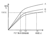
同様に、予め定めた車内温度及び予め定めた電源電圧の条件下で、予め定めたデューティ比及び周期のPWM制御によりFET26を駆動し、FET26の発熱温度を測定し、図2(B)に示すように、通電開始から過熱保護機能が作動する温度(例えば、150℃)に到達するまでの時間t2を測定する。
Similarly, the
FET26は、オン抵抗や、パッケージ(FET26の大きさ等)により、例えば、図2(B)のA〜Cのように発熱温度が異なるため、接続負荷28の過熱を検出したい温度に到達するまでの時間t1に一致する、過熱保護機能が作動する温度に到達するまでの時間t2のFET26を選定する。これによりFET26過熱保護起動が作動する温度に到達するまでの時間t2と、接続負荷28の過熱を検出したい温度に到達するまでの時間t1を対応させることができるので、FET26の発熱保護機能を利用することで、接続負荷28の過熱を防止することが可能となり、PTCサーミスタ等が不要となる。
The
ところで、上記ようにFET26を選定しても、前提とした条件(予め定めた車内温度及び予め定めた電源電圧の条件)から、電源電圧や車内温度が変化した場合には、接続負荷28としてのヒータの時間t1とFET26の時間t2とにずれが発生してしまう。
By the way, even if the
そこで、本実施の形態では、電源電圧監視部22及び車内温度監視部24の監視結果に基づいて、FET26をPWM制御で駆動する際のデューティ比及び周期の少なくとも一方を調整することにより、時間t1と時間t2のずれを補正するようになっている。
Therefore, in the present embodiment, the time t1 is adjusted by adjusting at least one of the duty ratio and the period when the
FET26をPWM制御する際のデューティ比及び周期の少なくとも一方を調整することにより、FET26の負荷発熱曲線が、図3のA〜Cのように変化するので、FET26の発熱保護検出温度(例えば、150℃)に達するまでの時間も変化する。図3の例では、発熱保護検出温度に達するまでの時間がt2〜t4に変化する。
By adjusting at least one of the duty ratio and the period when the
具体的には、デューティ比を大きくするとFET26の発熱量が増加し、デューティ比を小さくするとFET26の発熱量が減し、PWM周期を短くすると発熱量が増加し、PWM周期を長くすると発熱量が減少するので、これを利用して時間t1と時間t2を一致させる。
Specifically, when the duty ratio is increased, the heat generation amount of the
例えば、ヒータ負荷発熱時間>FET発熱時間の場合には、FET26は銅箔基板実装のためヒータ負荷に比べて放熱性がよいので、PWM制御のデューティ比を小さくすることにより、FET26の発熱を抑えて、ヒータ負荷とFET26の発熱時間を合わせ込むことが可能となる。或いは、PWM制御の周期を遅くすることにより、FET26のスイッチング損失が減少するため、FET26の発熱時間を遅くすることができ、ヒータ負荷とFET26の発熱時間を合わせる込むことが可能となる。
For example, when the heater load heat generation time is greater than the FET heat generation time, since the
また、ヒータ負荷発熱時間<FET発熱時間の場合には、PWM制御の周期を早くすることにより、FET26のスイッチング損失が増加するため、FET26の発熱時間を早めることができ、ヒータ負荷とFET26の発熱時間を合わせ込むことが可能となる。或いは、PWM制御のデューティ比を大きくすることにより、FET26の発熱量を増加させて、ヒータ負荷とFET26の発熱時間を合わせ込むことが可能となる。
Further, when the heater load heat generation time is smaller than the FET heat generation time, the switching loss of the
但し、上記のデューティ比及び周期の少なくとも一方を調整する制御は、電源電圧や車内温度の各種条件下で、PWM制御のデューティ比や周期を変更して予め測定しておく必要があり、測定した結果をテーブルや数式等の対応関係としてROM16に記憶しておき、記憶した対応関係に基づいて補正する。これにより、時間t1と時間t2とのずれを補正することが可能となる。
However, the control for adjusting at least one of the duty ratio and the cycle needs to be measured in advance by changing the duty ratio and the cycle of the PWM control under various conditions of the power supply voltage and the in-vehicle temperature. The result is stored in the
また、本実施の形態では、FET26の発熱保護機能を利用したハード的な過熱防止に加えて、ソフト的に接続負荷28の過熱を防止する機能を備えている。なお、ソフト的に接続負荷28の過熱を防止する機能は、上述の接続負荷過熱防止プログラムにより実現される。
Further, in the present embodiment, in addition to the hardware overheating prevention using the heat generation protection function of the
具体的には、電源電圧及び車内温度から接続負荷28の過熱を検出したい温度に到達するまでの時間t1を予測する。電源電圧及び車内温度が分かれば、PWM制御のデューティ比と周期から接続負荷28の過熱を検出したい温度に到達するまでの時間t1を予測することができるので、時間t1を予測して、予測した時間t1が経過したところでFET26の駆動を停止するFET26を制御すればよい。このとき、本実施の形態では、予測した時間t1が経過したところでFET26の駆動を停止せずに、予測した時間t1に対して予め定めた値を加えた時間が経過したところでFET26の駆動を停止するように制御するようになっている。これにより、ハード的な過熱防止が優先して行われ、ハード的な過熱防止のフェールセーフとしてソフト的な過熱の防止が行われる。すなわち、本実施の形態では、ハード及びソフトの2重のフェールセーフとされている。
Specifically, a time t1 until the temperature at which the overload of the
なお、本実施の形態では、基本的にはハード的な過熱防止(FET26の過熱保護機能を利用した過熱防止)を行うので、FET26の過熱保護機能を優先して、ソフト的な過熱防止を後に行うようになっているが、逆にソフト的な過熱防止を優先するようにしてもよい。この場合には、予測した時間t1から予め定めた値を引いた時間が経過したところでFET26の駆動を停止するように制御すればよい。
In the present embodiment, hardware overheating prevention (overheating prevention using the overheating protection function of the FET 26) is basically performed. Therefore, the overheating protection function of the
続いて、上述のように構成された本発明の実施の形態に係る車載用負荷過熱防止装置10の作用について説明する。図4は、本発明の実施の形態に係る車載用負荷過熱防止装置10のECU12で行われる処理の流れの一例を示すフローチャートである。なお、図4の処理は、上述した接続負荷過熱防止プログラムを実行することにより行われるものであり、接続負荷28のヒータがオンされた場合に開始し、ヒータがオフされた場合に終了するものとして説明する。
Then, the effect | action of the vehicle-mounted load
まず、ステップ100では、FET26の駆動が開始されると共に、時間カウントアップが開始されてステップ102へ移行する。すなわち、予め定めたデューティ比及び予め定めたPWM制御周期でFET26が駆動されることにより、電源30の電圧が接続負荷28としてのヒータに印加されて、ヒータが過熱される。また、同時に過熱開始からの時間を計数するための時間がCPU14によってカウントアップされる。
First, in
ステップ102では、電源電圧監視部22によって監視された電源30の電圧が取得されると共に、車内温度監視部24によって監視された車内温度が取得されてステップ104へ移行する。
In
ステップ104では、FET26の駆動補正を行う必要があるか否かCPU14によって判定される。該判定は、接続負荷28の過熱を検出したい温度までの時間t1と、FET26の発熱保護機能による発熱保護温度に達するまでの時間t2とがずれる条件であるか否かをステップ102の監視結果に基づいて判定し、該判定が肯定された場合にはステップ106へ移行し、否定された場合にはステップ108へ移行する。更に具体的には、例えば、取得した電源電圧や車内温度がFET26の駆動を補正する必要がある環境であるか否かを判定する。すなわち、ROM16に予め記憶したテーブルや数式(電源電圧や車内温度に対応するFET26を駆動するデューティ比やPWM制御周期)を用いて判定する。
In
ステップ106では、FET26の駆動補正が行われてステップ108へ移行する。すなわち、取得した電源電圧及び車内温度に基づいて、FET26を駆動するデューティ比及びPWM制御周期の少なくとも一方が変更される。これによって、接続負荷28の過熱を検出したい温度までの時間t1と、FET26の発熱保護機能による発熱保護温度に達するまでの時間t2とのずれが補正される。従って、FET26の発熱保護機能を利用して接続負荷28の過熱を確実に防止することができる。
In
ステップ108では、ステップ102で取得した電源電圧及び車内温度に基づいて、予測加熱時間(接続負荷28の過熱を検出したい温度に到達するまでの時間t1)が予測されてステップ110へ移行する。
In
ステップ110では、予測過熱時間になったか否か判定され、該判定が否定された場合にはステップ102へ戻って上述の処理が繰り返され、判定が肯定された場合にはステップ112へ移行する。
In
ステップ112では、FET26の駆動がCPU14によって停止されると共に、時間カウントアップがリセットされてステップ114へ移行する。これによって、故障等によってFET26の発熱保護機能が作動しなかった場合でも、FET26の駆動がソフト的に停止されるので、接続負荷28の過熱を確実に防止することができる。
In
ステップ114では、FET26の駆動再開か否か判定される。該判定は、例えば、予め定めた時間(FET26や接続負荷28が予め定めた温度以下となる時間)経過したか否かを判定し、該判定が肯定されるまで待機し、判定が肯定されたところで一連の処理をリターンして、ステップ100からの処理が再び開始される。
In
このように本実施の形態に係る車載用負荷過熱防止装置10では、接続負荷28の過熱を検出したい温度に到達するまでの時間t1に略一致する、過熱保護機能が作動する温度に到達するまでの時間t2のFET26を選定することにより、PTCサーミスタ等の効果なものを利用することなく、FET26の発熱保護機能を利用して接続負荷28の過熱を防止することができる。
As described above, in the in-vehicle load
また、上記処理を実行するにより、FET26の発熱保護機能によるハード的な過熱防止以外にソフト的にも接続負荷の過熱を防止することができるので、2重のフェールセーフで接続負荷28の過熱を確実に防止することができる。
Further, by executing the above processing, it is possible to prevent overheating of the connection load in terms of software in addition to the hardware overheating prevention by the heat generation protection function of the
なお、上記の実施の形態では、ハード的な過熱防止とソフト的な過熱防止を共に行う例を説明したが、どちらか一方のみを行うようにしてもよいが、ハード的な過熱防止の方がソフトの暴走等がないため、信頼性が高いので、どちらか一方のみを行う場合には、ハード的な過熱防止を行う方が好ましい。 In the above embodiment, an example of performing both hardware overheating prevention and software overheating prevention has been described. However, either one may be performed, but hardware overheating prevention is better. Since there is no software runaway and so on, the reliability is high. Therefore, when only one of them is performed, it is preferable to prevent hardware overheating.
10 車載用負荷過熱防止装置
12 ECU
22 電源監視部
24 車内温度監視部
26 FET
28 接続負荷
30 電源
10 On-vehicle load
22 Power
28 Connection load 30 Power supply
Claims (5)
前記負荷と前記電源との間に接続されると共に、予め定めた発熱保護温度になった場合に前記電源から前記負荷への電力供給を遮断するように作動する発熱保護機能を有し、前記負荷への電力供給開始から前記負荷が予め定めた過熱温度に達するまでの到達時間に対応しかつ前記発熱保護温度に上昇する発熱保護時間が経過した際に前記発熱保護機能が作動するスイッチング手段と、
前記電源の電力を前記負荷へ供給するように前記スイッチング手段を制御する制御手段と、
を備えた車両用負荷過熱防止装置。 A load mounted on an automobile and driven by power from a predetermined power source;
The load is connected between the load and the power source, and has a heat generation protection function that operates to cut off power supply from the power source to the load when a predetermined heat generation protection temperature is reached. Switching means in which the heat generation protection function is activated when a heat generation protection time corresponding to an arrival time from the start of power supply to the load reaching a predetermined overheat temperature and rising to the heat generation protection temperature has elapsed,
Control means for controlling the switching means to supply power of the power source to the load;
A vehicle load overheat prevention device comprising:
前記制御手段が、前記電圧検出手段及び前記温度検出手段の検出結果に基づいて、前記到達時間と前記発熱保護時間との対応のずれを補正するように、前記スイッチング手段を更に制御する請求項1に記載の車両用負荷過熱防止装置。 Voltage detection means for detecting the voltage of the power supply; and temperature detection means for detecting the temperature inside the automobile;
The control means further controls the switching means so as to correct a corresponding deviation between the arrival time and the heat generation protection time based on detection results of the voltage detection means and the temperature detection means. The vehicle load overheat prevention device according to claim 1.
前記制御手段が、前記電圧検出手段及び前記温度検出手段の検出結果に基づいて、前記到達時間を更に予測し、予測した前記到達時間になったところで前記負荷への電力の供給を停止するように前記スイッチング手段を更に制御する請求項1〜3の何れか1項に記載の車載用負荷過熱防止装置。 Voltage detection means for detecting the voltage of the power supply; and temperature detection means for detecting the temperature inside the automobile;
The control means further predicts the arrival time based on the detection results of the voltage detection means and the temperature detection means, and stops supplying power to the load when the predicted arrival time is reached. The in-vehicle load overheat prevention device according to any one of claims 1 to 3, further controlling the switching means.
Priority Applications (1)
| Application Number | Priority Date | Filing Date | Title |
|---|---|---|---|
| JP2013058571A JP2014181012A (en) | 2013-03-21 | 2013-03-21 | On-vehicle load overheat preventive apparatus |
Applications Claiming Priority (1)
| Application Number | Priority Date | Filing Date | Title |
|---|---|---|---|
| JP2013058571A JP2014181012A (en) | 2013-03-21 | 2013-03-21 | On-vehicle load overheat preventive apparatus |
Publications (1)
| Publication Number | Publication Date |
|---|---|
| JP2014181012A true JP2014181012A (en) | 2014-09-29 |
Family
ID=51700114
Family Applications (1)
| Application Number | Title | Priority Date | Filing Date |
|---|---|---|---|
| JP2013058571A Pending JP2014181012A (en) | 2013-03-21 | 2013-03-21 | On-vehicle load overheat preventive apparatus |
Country Status (1)
| Country | Link |
|---|---|
| JP (1) | JP2014181012A (en) |
Cited By (1)
| Publication number | Priority date | Publication date | Assignee | Title |
|---|---|---|---|---|
| JP2022506379A (en) * | 2018-11-06 | 2022-01-17 | ヴァレオ システム テルミク | How to detect overheating of heating equipment and the corresponding control unit |
-
2013
- 2013-03-21 JP JP2013058571A patent/JP2014181012A/en active Pending
Cited By (2)
| Publication number | Priority date | Publication date | Assignee | Title |
|---|---|---|---|---|
| JP2022506379A (en) * | 2018-11-06 | 2022-01-17 | ヴァレオ システム テルミク | How to detect overheating of heating equipment and the corresponding control unit |
| JP7138789B2 (en) | 2018-11-06 | 2022-09-16 | ヴァレオ システム テルミク | A method for detecting overheating of a heating device and a corresponding control unit |
Similar Documents
| Publication | Publication Date | Title |
|---|---|---|
| JP4964536B2 (en) | Motor abnormality detection device and method | |
| JP5647501B2 (en) | Vehicle power distribution device | |
| US7782584B2 (en) | Load drive controller and control system | |
| CA2851811C (en) | Apparatus for controlling in-vehicle heater | |
| JP2009289689A (en) | Relay control device | |
| US10199982B2 (en) | Motor control apparatus | |
| JP5944729B2 (en) | Protection device for energization circuit | |
| JP6623829B2 (en) | Overheat protection device | |
| JP2003291632A (en) | Electric heater, motor vehicle using the same, and electric heater control unit | |
| US20180326816A1 (en) | Heating device | |
| US9300200B2 (en) | DC-DC converter that supplies voltage of a DC power supply to a load while boosting or stepping down the voltage of the DC power supply | |
| JP2008025547A (en) | Igniter for internal combustion engine | |
| JP4802948B2 (en) | Load drive control device | |
| JP4438668B2 (en) | Motor controller for vehicle for EPS | |
| JP2006044437A (en) | Electric power steering device | |
| JP2014181012A (en) | On-vehicle load overheat preventive apparatus | |
| JP2009051255A (en) | Control device of electric power steering device | |
| JP5163251B2 (en) | Control device for electric power steering device | |
| JP6245092B2 (en) | Current control device | |
| JP5018333B2 (en) | Control device for electric power steering device | |
| JP6090054B2 (en) | Load drive device | |
| JP2016170126A (en) | Abnormality sensing unit | |
| JP4792820B2 (en) | Control device for electric power steering device | |
| JP6831052B2 (en) | Leakage current detector and heating device | |
| WO2023062733A1 (en) | Vehicle-mounted control device |