JP2014178574A - Image forming apparatus - Google Patents
Image forming apparatus Download PDFInfo
- Publication number
- JP2014178574A JP2014178574A JP2013053434A JP2013053434A JP2014178574A JP 2014178574 A JP2014178574 A JP 2014178574A JP 2013053434 A JP2013053434 A JP 2013053434A JP 2013053434 A JP2013053434 A JP 2013053434A JP 2014178574 A JP2014178574 A JP 2014178574A
- Authority
- JP
- Japan
- Prior art keywords
- transfer material
- fixing
- recording medium
- image forming
- smoothness
- Prior art date
- Legal status (The legal status is an assumption and is not a legal conclusion. Google has not performed a legal analysis and makes no representation as to the accuracy of the status listed.)
- Pending
Links
Images


Landscapes
- Fixing For Electrophotography (AREA)
- Control Or Security For Electrophotography (AREA)
Abstract
Description
本発明は、複写機、ファクシミリ、プリンタまたはこれらの複合機等の画像形成装置に関する。 The present invention relates to an image forming apparatus such as a copying machine, a facsimile, a printer, or a complex machine of these.
デジタル複写機、レーザプリンタ等のいわゆる電子写真方式の画像形成装置は、記録紙等の記録媒体にトナー像を転写し、所定の条件で加熱および加圧することによりトナー像を記録紙等の記録媒体に定着させて画像を形成するものである。 A so-called electrophotographic image forming apparatus such as a digital copying machine or a laser printer transfers a toner image to a recording medium such as recording paper, and heats and presses the toner image under a predetermined condition to record the toner image on a recording medium such as recording paper. To form an image.
このような画像形成装置においては、トナー像を定着する際の加熱量や圧力等の条件を考慮する必要がある。特に、高画質な画像形成を行う際には、トナー像を定着するための条件を記録媒体の種類に応じて個別に設定する必要がある。 In such an image forming apparatus, it is necessary to consider conditions such as a heating amount and a pressure when fixing a toner image. In particular, when forming a high-quality image, it is necessary to individually set conditions for fixing the toner image according to the type of the recording medium.
これは、記録媒体に記録される画像品質が、記録媒体の材質、厚さ、湿度、平滑性および塗工状態等により大きく影響されるためである。例えば平滑性を表す指標として、平滑度がある。平滑度は、紙面と試験板を密着させた時に、その間を一定量の空気が流れる時間[sec]で表したものである。なお、塗工とは、インクや塗料などをコーティングまたは印刷されていることを意味する。 This is because the image quality recorded on the recording medium is greatly influenced by the material, thickness, humidity, smoothness, coating state, and the like of the recording medium. For example, there is smoothness as an index representing smoothness. The smoothness is expressed by the time [sec] in which a certain amount of air flows between the paper surface and the test plate when they are brought into close contact with each other. The term “coating” means that ink or paint is coated or printed.
ここで、記録媒体の平滑度と定着品質には極めて高い相関がある。これは、記録媒体における凹凸の程度により凹部におけるトナーの定着率が変化するためである。したがって、平滑度を考慮した定着条件で定着を行わない場合には、高画質な画像を得ることができないばかりか、場合によっては定着不良などの異常画像を引き起こすおそれがある。 Here, there is a very high correlation between the smoothness of the recording medium and the fixing quality. This is because the toner fixing rate in the recesses changes depending on the degree of unevenness in the recording medium. Therefore, when fixing is not performed under fixing conditions that take smoothness into account, not only a high-quality image can be obtained, but also an abnormal image such as fixing failure may be caused in some cases.
一方、近年の画像形成装置の進歩と表現方法の多様化に伴い、記録媒体となる記録紙の種類は、数百種類以上存在し、さらに、各々の記録紙の種類において坪量や厚さ等の違いにより多岐にわたる銘柄が存在している。このため、高画質な画像を形成するためには、記録紙等の記録媒体の種類や銘柄等に応じて、詳細な定着条件等を設定する必要がある。 On the other hand, with the recent progress of image forming apparatuses and diversification of expression methods, there are several hundred types of recording papers that serve as recording media, and the basis weight, thickness, etc. for each type of recording paper There are various brands due to the difference. Therefore, in order to form a high-quality image, it is necessary to set detailed fixing conditions and the like according to the type and brand of a recording medium such as recording paper.
例えば記録媒体の種別としては、普通紙、グロスコート紙、マットコート紙、アートコート紙等の塗工紙、OHPシート等の他に、紙の表面にエンボス加工を施した特殊紙等も存在している。こうした特殊紙は、近年、増加しつつある。なお、記録媒体としては、記録紙等以外の記録媒体も存在している。 For example, the types of recording media include plain paper, gloss coated paper, matte coated paper, coated paper such as art coated paper, OHP sheets, etc., as well as special paper with a paper surface embossed. ing. These special papers are increasing in recent years. Note that recording media other than recording paper and the like exist as recording media.
ところで、現状の画像形成装置において、定着条件の設定は、記録材の坪量に応じて設定されていることが極めて一般的である。例えば坪量60〜90g/m2の紙を普通紙、91〜105g/m2を中厚紙、106〜200g/m2を厚紙といった具合に、坪量に応じて分類がなされており、各分類ごとに定着温度や記録媒体の搬送速度等を変更している。 By the way, in the current image forming apparatus, it is very general that the fixing condition is set according to the basis weight of the recording material. For example, paper with a basis weight of 60 to 90 g / m 2 is plain paper, 91 to 105 g / m 2 is medium thick paper, 106 to 200 g / m 2 is thick paper, and so on. The fixing temperature, the recording medium conveyance speed, and the like are changed every time.
記録材の坪量情報は、一般に記録材のパッケージ等に記載されており、ユーザ自身が把握することができる。この坪量情報は、コピー機であれば操作部(オペレーションパネル)上で、プリンタであればPCディスプレイに表示されたプリンタドライバ上で選択することにより認識することができる。 The basis weight information of the recording material is generally described in a recording material package or the like, and can be grasped by the user. This basis weight information can be recognized by selecting it on the operation unit (operation panel) if it is a copier, or on the printer driver displayed on the PC display if it is a printer.
一般に、ユーザは、自ら上記坪量情報を設定する必要があり、印刷等を行う場合に煩わしいことに加え、誤って設定した場合に所望の高画質な画像を得ることができないことがある。 In general, the user needs to set the basis weight information by himself / herself. In addition to being troublesome when performing printing or the like, the user may not be able to obtain a desired high-quality image if set incorrectly.
そこで、従来、画像形成装置において、例えば記録媒体の厚みを検知するセンサを搭載し、自動で記録媒体の選別を行い画像形成することのできる画像形成装置に関する技術が検討されている。 Therefore, conventionally, a technique relating to an image forming apparatus that is equipped with a sensor that detects the thickness of a recording medium, for example, and that can automatically select the recording medium to form an image has been studied.
一方、記録媒体の平滑度は、通常、記録材のパッケージには印字されておらず、平滑度情報をユーザ自身が知ることは極めて困難である。このため、記録媒体の平滑度は、センサなどを用いて入手せざるを得なかった。 On the other hand, the smoothness of the recording medium is usually not printed on the recording material package, and it is extremely difficult for the user to know the smoothness information. For this reason, the smoothness of the recording medium has to be obtained using a sensor or the like.
前述したように、平滑度と定着品質には高い相関があるが、平滑度は、記録材と試験片との間に空気が一定量流れる時間であるから、短時間での検出が困難である。そこで、従来、平滑度の代用特性として、平滑度と高い相関のある表面粗さや光の反射光量を計測するセンサが検討されてきた。 As described above, there is a high correlation between the smoothness and the fixing quality, but the smoothness is the time during which a certain amount of air flows between the recording material and the test piece, so that it is difficult to detect in a short time. . Therefore, conventionally, as a substitute characteristic of smoothness, a sensor that measures surface roughness and light reflected light quantity highly correlated with smoothness has been studied.
従来、こうした平滑度の検出方法として、発光ダイオード(LED:Light Emitting Diode)等の光源から発せられた光を記録媒体に照射し、記録媒体からの反射光量により記録媒体の平滑度を検出する反射光方式が知られている。この反射光方式によれば、記録媒体に対して非接触で平滑度を検出できるので、記録媒体へのダメージがないという利点を有する。 Conventionally, as a method for detecting such smoothness, reflection is performed by irradiating a recording medium with light emitted from a light source such as a light emitting diode (LED) and detecting the smoothness of the recording medium based on the amount of reflected light from the recording medium. An optical system is known. According to this reflected light method, since the smoothness can be detected without contact with the recording medium, there is an advantage that there is no damage to the recording medium.
この種の反射光方式の平滑度検出方法として、例えば記録媒体の表面に照射された光の正反射方向における反射光の光量を検出し、検出された正反射方向における光量に基づき記録媒体の平滑度を検出する方法が知られている(例えば、特許文献1参照)。 As this type of reflected light smoothness detection method, for example, the amount of reflected light in the regular reflection direction of light irradiated on the surface of the recording medium is detected, and the smoothness of the recording medium is detected based on the detected amount of light in the regular reflection direction. A method of detecting the degree is known (for example, see Patent Document 1).
また、光量検出部を複数有し、記録媒体の表面に照射された光の正反射方向における反射光の光量のみならず、散乱反射光の光量を検出し、これら2つの光量に基づき記録媒体の平滑度を識別する方法も知られている(例えば、特許文献2参照)。 In addition, it has a plurality of light amount detection units, detects not only the amount of reflected light in the regular reflection direction of the light irradiated on the surface of the recording medium but also the amount of scattered reflected light, and based on these two amounts of light, A method for identifying smoothness is also known (see, for example, Patent Document 2).
こうした検出方法で検出された平滑度は、例えば定着温度等の定着条件や画像形成条件等の設定に利用される。また、画像形成開始から転写紙上への転写まで、および実際の定着温度が目標定着温度に達するまでには、所定の時間を要する。 The smoothness detected by such a detection method is used, for example, for setting fixing conditions such as fixing temperature and image forming conditions. Further, a predetermined time is required from the start of image formation to transfer onto transfer paper and until the actual fixing temperature reaches the target fixing temperature.
したがって、検出した記録媒体の平滑度を定着条件や画像形成条件の設定に用いる画像形成装置にあっては、前述したような所定の時間を考慮して前以て平滑度の検出を行う必要があり、平滑度検出用のセンサの配置や検知タイミングが特に重要である。 Therefore, in an image forming apparatus that uses the detected smoothness of the recording medium for setting the fixing conditions and the image forming conditions, it is necessary to detect the smoothness in advance in consideration of the predetermined time as described above. In particular, the arrangement and detection timing of the sensor for detecting the smoothness are particularly important.
また、画像形成装置のなかには、記録媒体の厚みを検出する紙厚検出センサ等を備え、記録媒体の厚みに応じて定着条件を変更するものもある。こうした画像形成装置においても、適切な定着条件の設定のためには紙厚検出センサ等の配置や検知タイミングが重要となる。 Some image forming apparatuses include a paper thickness detection sensor for detecting the thickness of the recording medium, and the fixing conditions are changed according to the thickness of the recording medium. Even in such an image forming apparatus, arrangement and detection timing of a paper thickness detection sensor and the like are important for setting appropriate fixing conditions.
しかしながら、上述の特許文献1、2に記載の画像形成装置にあっては、画像形成開始から転写紙上への転写までの時間、および実際の定着温度が目標定着温度に達するまでの時間を考慮して最適な位置に平滑度検出用のセンサを配置することや、最適なタイミングで検知を行うことについてなんら考慮されていない。
However, in the image forming apparatuses described in
また、平滑度用のセンサに限らず、紙厚検出センサにあっても、平滑度用のセンサと同様、実際の定着温度が目標定着温度に達するまでの時間を考慮してその配置や検知タイミングを適切に設定する必要がある。 Further, not only the smoothness sensor but also the paper thickness detection sensor, like the smoothness sensor, its arrangement and detection timing in consideration of the time until the actual fixing temperature reaches the target fixing temperature. Must be set appropriately.
本発明は、上述のような事情に鑑みてなされたもので、転写材の種別に応じて定着条件の設定を適切に行うことができる画像形成装置を提供することを目的とする。 SUMMARY An advantage of some aspects of the invention is that it provides an image forming apparatus capable of appropriately setting fixing conditions according to the type of transfer material.
本発明に係る画像形成装置は、上記目的を達成するため、転写材上にトナー像を形成する画像形成手段と、前記転写材上に形成されたトナー像を目標定着温度に基づき加熱して前記転写材上に定着させる定着手段と、前記目標定着温度の設定に際して使用される前記転写材の種別を検出する検出手段と、前記検出手段の検出値に応じて前記目標定着温度を決定する定着制御手段と、を備え、前記検出手段により種別が検出された転写材を転写材P、前記転写材Pの次に搬送される転写材を転写材Qとしたとき、前記定着制御手段は、前記検出手段によって検出された複数の転写材Pの検出値に応じて前記転写材Qに対する前記目標定着温度を決定する構成を有する。 In order to achieve the above object, an image forming apparatus according to the present invention forms an image forming means for forming a toner image on a transfer material, and heats the toner image formed on the transfer material on the basis of a target fixing temperature. Fixing means for fixing on the transfer material, detection means for detecting the type of the transfer material used when setting the target fixing temperature, and fixing control for determining the target fixing temperature according to the detection value of the detection means A transfer material whose type is detected by the detection means is a transfer material P, and a transfer material conveyed next to the transfer material P is a transfer material Q. The target fixing temperature for the transfer material Q is determined according to the detected values of the plurality of transfer materials P detected by the means.
本発明によれば、転写材の種別に応じて定着条件の設定を適切に行うことができる画像形成装置を提供することができる。 According to the present invention, it is possible to provide an image forming apparatus capable of appropriately setting fixing conditions according to the type of transfer material.
以下、本発明の実施の形態について、図面を参照して説明する。 Embodiments of the present invention will be described below with reference to the drawings.
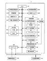
図1は、一般的な電子写真方式の画像形成装置における内部構成の一例を概略で示した断面図である。画像形成装置1は、画像形成装置本体100と、画像読取装置200と、両面ユニット300とから構成されている。
FIG. 1 is a cross-sectional view schematically illustrating an example of an internal configuration of a general electrophotographic image forming apparatus. The
画像形成装置本体100は、中間転写ベルト11と、作像装置12c、12m、12y、12kと、露光装置13と、給紙装置14と、記録媒体搬送路16と、給紙コロ17と、胴内排紙部18と、排紙装置23とを備えている。また、画像形成装置本体100は、一次転写装置25c、25m、25y、25kと、光学センサ50と、定着装置60とを備えている。
The image forming apparatus
中間転写ベルト11は、画像形成装置本体100内に設けられた複数のローラに掛け回され、ほぼ水平に張り渡された無端状のベルトであり、図中反時計方向に走行するように構成されている。ここで、無端状とは、ベルトの両端部を接合し、かつ、つなぎ目が存在しない状態をいう。
The
作像装置12c、12m、12y、12kは、シアン、マゼンタ、イエロー、ブラックの各色に対応しており、中間転写ベルト11の下方において中間転写ベルト11の走行方向に沿って四連タンデム式に並べて設けられている。
The
また、作像装置12c、12m、12y、12kは、図中時計方向に回転するドラム状の像担持体と、像担持体の周囲に設けられた帯電装置、現像装置、転写装置およびクリーニング装置等とによって構成される。
The
露光装置13は、作像装置12c、12m、12y、12kの下方に設けられる。露光装置13は、画像読取装置200で読取られた原稿画像の各色トナー像に対応した潜像を、帯電装置によって帯電した各作像装置12c、12m、12y、12kの像担持体上に書き込む。
The
給紙装置14は、露光装置13の下方に設けられており、転写材としての記録媒体Sを積層して収納する複数の給紙カセット15を有する。なお、図1において、給紙カセット15が2つ設けられているが、これは例示であり、本発明は、これに限定されるものではない。
The
記録媒体搬送路16は、画像形成装置本体100内部における右側方に、垂直上方に向けて形成されており、画像形成装置本体100と画像読取装置200との間に形成された胴内排紙部18へと通じている。
The recording
記録媒体搬送路16には、記録媒体Sの搬送方向上流側から下流側に沿って順に、記録媒体Sを搬送する搬送ローラ19と、中間転写ベルト11に対向する二次転写装置21と、定着装置60と、排紙装置23とが設けられている。また、記録媒体搬送路16には、定着装置60の記録媒体搬送方向下流側に、両面ユニット300への再給紙搬送路が分岐されて設けられている。
In the recording
給紙コロ17は、図1中各給紙カセット15の右上に設けられており、各給紙カセット15内の記録媒体Sを1枚ずつ繰り出して記録媒体搬送路16に送り込む。
The
胴内排紙部18は、画像形成装置本体100と画像読取装置200との間に形成され、排紙装置23から排紙された記録媒体Sがスタックされる。
The in-
一次転写装置25c、25m、25y、25kは、各作像装置12c、12m、12y、12kの像担持体と中間転写ベルト11との双方に接するよう設けられている。一次転写装置25c、25m、25y、25kは、各作像装置12c、12m、12y、12kの像担持体上のトナー像を順次中間転写ベルト11上に一次転写することで、中間転写ベルト11上に所望のカラー画像を形成する。
The
光学センサ50は、搬送ローラ19の下流側に設けられており、給紙カセット15または手差し給紙装置36から記録媒体搬送路16に搬送された記録媒体Sの平滑度を算出する。光学センサ50は、算出した記録媒体Sの平滑度から、後述する定着設定温度(目標定着温度)を含む定着条件の設定に際して使用される記録媒体Sの種別を検出するようになっている。本実施の形態における光学センサ50は、検出手段を構成する。
The
なお、記録媒体Sの種別を検出する検出手段としては、上記光学センサ50の他、例えば記録媒体Sの厚みを検出し、この検出結果に基づき記録媒体Sの種別を検出する紙厚センサ等を用いることができる。紙厚センサとしては、例えば複数のセンサ間における記録媒体Sの搬送時間から紙厚を特定するものや、記録媒体Sの先端の映像を読み取ることで記録媒体Sの厚さに比例して発生する記録媒体Sの影の面積の変化から紙厚を特定するもの、あるいは複数の記録媒体からなる紙束の一方の面に光を照射し、その漏れ光を紙束の側面から検知することにより紙厚を特定するもの等、種々の構成の紙厚センサを用いることができる。
As the detection means for detecting the type of the recording medium S, in addition to the
光学センサ50を搬送ローラ19の下流側に設けることで、画像形成装置1は、各給紙カセット15および手差し給紙装置36のすべてに光学センサ50を設置することなく、記録媒体搬送路16を通過するすべての記録媒体Sの平滑度を算出することができる。
By providing the
光学センサ50の画像形成装置内の搭載方式としては、各給紙カセット15に積載された最上位の記録媒体Sの近傍に設置して記録媒体Sの表面を検出する方式が考えられるが、このような場合には光学センサ50の数が増えてコスト高になる。また、記録媒体Sを給紙カセット15にセットする際、光学センサ50と記録媒体Sの距離が近いので操作の邪魔になり給紙カセット15の開閉と同期したセンサ解除(開放して最上位の記録媒体Sから離す等)機構も必要となって機構が複雑になる。このため、本実施の形態では、光学センサ50を上記の通り搬送ローラ19の下流側に設けることで上記不具合を解消している。なお、光学センサ50の詳細については、後述する。
As a method of mounting the
搬送ローラ19の記録媒体搬送方向上流側には、給紙路37が設けられている。給紙路37は、一旦画像が表面に形成、定着された記録媒体Sを両面ユニット300から再度記録媒体搬送路16へ再給紙するため、または、両面ユニット300を横切って手差し給紙装置36から記録媒体Sを手差し給紙するために設けられている。また、給紙路37は、記録媒体搬送路16に合流している。
A
二次転写装置21は、中間転写ベルト11と二次転写装置21との間に形成された二次転写位置において、中間転写ベルト11上に形成されたトナー像を記録媒体Sに転写する。本実施の形態のおける一次転写装置25c、25m、25y、25kおよび二次転写装置21は、記録媒体S上にトナー像を形成する画像形成手段を構成する。
The
定着装置60は、記録媒体S上に形成されたトナー像を後述する定着設定温度(目標定着温度)に基づき加熱して記録媒体S上に定着させるものである。具体的には、定着装置60は、記録媒体Sに熱を加える加熱部材と、記録媒体Sに圧力を加える加圧部材とを有する。定着装置60は、加熱部材および加圧部材の間に形成されたニップ部において記録媒体Sを加熱および加圧し、記録媒体S上の未定着のトナー像を記録媒体Sに定着させる。本実施の形態における定着装置60は、定着手段を構成する。
The fixing
次に、画像形成装置1でコピーを取る場合における画像形成動作について説明する。
Next, an image forming operation when the
まず、画像形成装置1は、画像読取装置200で読取った原稿画像の各色トナー像に対応した潜像を、帯電装置によって一様に帯電した各作像装置12c、12m、12y、12kの像担持体上に、露光装置13を用いて書き込む。
First, the
次いで、画像形成装置1は、各作像装置12c、12m、12y、12kの像担持体上の各色トナー潜像に、現像装置から各色トナーを付与することで、トナー像を形成する。
Next, the
次いで、画像形成装置1は、像担持体上に形成された各色トナー像を、一次転写装置25c、25m、25y、25kを用いて、順次中間転写ベルト11上に一次転写することで、中間転写ベルト11上に所望のカラー画像を形成する。
Next, the
一方で、画像形成装置1は、二段構成の給紙カセットにおける給紙コロ17の一方を選択的に回転させて対応する給紙カセット15から記録媒体Sを繰り出すか、手差し給紙装置36から給紙路37に手差しの記録媒体Sを繰り出す。
On the other hand, the
次いで、画像形成装置1は、給紙カセット15または手差し給紙装置36から繰り出した記録媒体Sを記録媒体搬送路16に搬入する。
Next, the
次いで、画像形成装置1は、記録媒体搬送路16を通して搬送ローラ19まで搬送された記録媒体Sを、搬送ローラ19により、中間転写ベルト11上に形成されたトナー像とタイミングを取って二次転写装置21の二次転写位置に送り込む。
Next, the
ここで、画像形成装置1は、光学センサ50によって記録媒体Sの平滑度を算出するとともに、二次転写装置21によって中間転写ベルト11上のカラー画像を記録媒体Sに転写する。
Here, the
次いで、画像形成装置1は、カラー画像が転写された記録媒体Sを定着装置60に搬送し、定着装置60のニップ部において加熱および加圧することで、記録媒体Sにカラー画像を定着する。
Next, the
ここで、記録媒体Sの裏面にも画像を形成する場合、画像形成装置1は、片面にカラー画像が定着した記録媒体Sを、搬送経路を切り替える切替爪(不図示)を利用して、再給紙搬送路24に搬入し、両面ユニット300に搬送する。
Here, when an image is also formed on the back surface of the recording medium S, the
そして、記録媒体Sは、両面ユニット300を通過する場合に、その表面と裏面とを反転させられたのちに給紙路37に搬入され、給紙路37を通して、記録媒体搬送路16に再給紙される。
When the recording medium S passes through the
記録媒体Sが再給紙された後に、画像形成装置1は、中間転写ベルト11上に形成された裏面用のカラー画像を、表面の場合と同様に記録媒体Sに二次転写し、定着装置60によって二次転写されたカラー画像を定着する。
After the recording medium S is re-fed, the
記録媒体Sへのカラー画像の定着がすべて終了すると、画像形成装置1は、排紙装置23によってカラー画像の定着した記録媒体Sを、胴内排紙部18上に排紙し、記録媒体Sがスタックされることで画像形成動作が完了する。
When all the fixing of the color image to the recording medium S is completed, the
図2は、光学センサ50の構成について説明する図である。
FIG. 2 is a diagram illustrating the configuration of the
光学センサ50は、光源51と、コリメートレンズ52と、光検出器としての正反射光検出器53と、アパーチャ54と、制御部55とを含んで構成されている。
The
光源51は、面発光レーザ(VCSEL:Vertical Cavity Surface Emitting Laser)によって構成されている。そのため、光源51は、安定した光源として一般的なLEDや端面LD(Laser Diode)を使用する場合よりも、FFP(Far Field Pattern)を抑えることができ、より精度のよい光学系を形成することができる。ここで、FFPとは、ビームの広がり角を意味する値である。なお、光源51は、面発光レーザに限らず、LED等の各種光源によって構成されていてもよい。 The light source 51 is configured by a surface emitting laser (VCSEL: Vertical Cavity Surface Emitting Laser). Therefore, the light source 51 can suppress FFP (Far Field Pattern) and form a more accurate optical system than a case where a general LED or an end face LD (Laser Diode) is used as a stable light source. Can do. Here, FFP is a value that means the beam divergence angle. The light source 51 is not limited to a surface emitting laser, and may be configured by various light sources such as LEDs.
コリメートレンズ52は、光源51と記録媒体Sの照射面との間に設けられ、光源51から照射される光をコリメート光に変換する凸面のレンズである。ここで、コリメートとは、光源から発せられるレーザ光を拡散、収束しない平行な光の束にすることを意味し、コリメート光とは、平行な状態に調整されたレーザ光を意味する。 The collimating lens 52 is a convex lens that is provided between the light source 51 and the irradiation surface of the recording medium S and converts light emitted from the light source 51 into collimated light. Here, the collimate means that the laser light emitted from the light source is made into a bundle of parallel light that is not diffused and converged, and the collimated light means the laser light adjusted to be in a parallel state.
コリメートレンズ52によって光源51から照射されるレーザ光の記録媒体Sへの入射角およびコリメート光の平行性を調整することにより、光学センサ50は、記録媒体Sの平滑度の検出感度を上昇させることができる。
The
正反射光検出器53は、光源51から照射されるレーザ光の方向において、記録媒体Sの反射面よりも下流側に設けられており、記録媒体Sに正反射された光を検出するフォトダイオード等から構成されている。
The regular
正反射光検出器53は、記録媒体Sに正反射された光の強度を電圧として検出し、検出した結果を出力信号として制御部55に出力する。これにより、光学センサ50は、記録媒体Sの平滑度を制御部55によって算出することができる。
The regular
アパーチャ54は、記録媒体Sの照射面と正反射光検出器53との間に設けられ、正反射光検出器53に入社する光の入射角を制限する。アパーチャ54を設けることにより、光学センサ50は、光源51から照射され記録媒体Sの照射面で反射された反射光の光量を確保しつつ、反射光に混じった散乱光を制限することができ、平滑度検出の精度が低下することを防ぐことができる。
The
制御部55は、正反射光検出器53に接続されており、正反射光検出器53によって検出されたセンサ値(検出値)から記録媒体Sの平滑度を算出する。なお、制御部55の機能については、後述する。
The
このように構成された光学センサ50は、光源51により記録媒体Sに照射された光の正反射方向における正反射光の光の強度を検出することにより記録媒体Sの表面の平滑度を検出するようになっている。本実施の形態における光学センサ50は、平滑度検出手段を構成する。
The
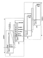
図3は、画像形成装置1の各構成を示す機能ブロック図である。
FIG. 3 is a functional block diagram showing each configuration of the
図3において、画像形成装置1は、CPU101にバスを介して各要素が接続され、CPU101が各要素を制御し、画像形成装置1の機能を発揮できるようにしている。
In FIG. 3, the
CPU101には、給紙カセット15と、記録媒体搬送路16と、二次転写装置21と、排紙装置23と、手差し給紙装置36と、定着装置60と、メモリ部102と、A/D変換部106と、電圧検出部107と、インターフェース108とが接続されている。また、CPU101には、画像読取装置200と、両面ユニット300とが接続されている。
The
定着装置60は、熱源62が加熱部材に供給する熱量(以下、「供給熱量」という)、すなわち定着設定温度(目標定着温度)を決定する熱源制御回路61と、加熱部材および加圧部材の温度を検出するサーミスタ64とを備えている。
The fixing
ここで、上述したように高画質な画像を得るためには、定着品質と極めて高い相関のある平滑度を考慮して定着設定温度(目標定着温度)を決定する必要がある。したがって、本実施の形態に係る熱源制御回路61は、上述の光学センサ50のセンサ値、すなわち光学センサ50で検出された記録媒体Sの表面の平滑度に応じて定着設定温度(目標定着温度)を決定する。本実施の形態における熱源制御回路61は、定着制御手段を構成する。
Here, in order to obtain a high-quality image as described above, it is necessary to determine the fixing setting temperature (target fixing temperature) in consideration of smoothness having a very high correlation with the fixing quality. Accordingly, the heat
また、定着装置60は、サーミスタ64で検出したアナログ値をCPUで処理するためにデジタル値にA/D変換してCPU101に通知するA/D変換部63を備えている。また、定着装置60は、加圧部材を加熱部材に押付ける力およびニップ部の幅を制御する加圧制御回路65を備えている。
Further, the fixing
また、定着装置60には、光学センサ50の制御部55が接続されており、制御部55から送信される信号を定着装置60が受信することで、熱源制御回路61および加圧制御回路65の制御が実行される。
Further, the
メモリ部102は、ROM(Read Only Memory)103と、RAM(Random Access Memory)104とから構成されている。ROM103には、CPU101が実行するプログラムコードと、定着制御パターンが格納されている。また、RAM104には、検出電圧が1次的に格納される。
The
CPU101は、ROM103に格納されたプログラムコードを読み出し、RAM104に展開し、RAM104をデータバッファとしても使用しながらプログラムコードで定義されたプログラムを実行し、各要素を制御する。
The
電流制御回路105は、光学センサ50の制御部55から送信される信号を受信し、二次転写装置21がトナー像を記録媒体Sに転写する場合の転写電流値を制御する要素である。
The
A/D変換部106は、安定した電力状態で制御を行うために電圧検出を行う電圧検出部107が検出したアナログ電圧を、CPU101で処理するためにデジタル値に変換し、CPU101に通知する要素である。
The A / D conversion unit 106 converts the analog voltage detected by the voltage detection unit 107 that performs voltage detection in order to perform control in a stable power state into a digital value for processing by the
インターフェース108は、ハードディスク装置などの外部記憶素子109やパソコンなどの外部通信機器110と接続する接続手段として機能し、外部から画像形成装置1内に画像データを取り込む。
The
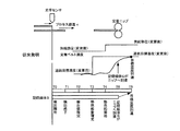
次に、図4を参照して、本実施の形態に係る光学センサ50と同様の平滑度検出用の光学センサを備えた従来の画像形成装置における定着処理について説明する。
Next, with reference to FIG. 4, a fixing process in a conventional image forming apparatus provided with an optical sensor for detecting smoothness similar to the
図4に示すように、従来の定着処理においては、まず記録媒体Sの先端が光学センサに達すると、光学センサによって記録媒体Sの平滑度の検出が開始される(時間T0)。ここで、時間T0は、記録媒体Sの先端が光学センサと対向する面に到達した時点を意味する。 As shown in FIG. 4, in the conventional fixing process, when the leading edge of the recording medium S reaches the optical sensor, the optical sensor starts detecting the smoothness of the recording medium S (time T0). Here, the time T0 means the time when the leading edge of the recording medium S reaches the surface facing the optical sensor.
その後、光学センサは、プロセス線速(搬送速度)vで搬送される記録媒体Sの検出を時間T0から時間T1まで実施する。すなわち、記録媒体Sの検出は、時間T1で終了する。この処理において、光学センサは、光源からコリメートレンズを介して照射されるレーザ光を時間T1になるまで記録媒体Sの印字面に照射する。 Thereafter, the optical sensor detects the recording medium S conveyed at the process linear velocity (conveyance speed) v from time T0 to time T1. That is, the detection of the recording medium S ends at time T1. In this process, the optical sensor irradiates the print surface of the recording medium S with laser light emitted from the light source through the collimator lens until time T1.
そして、記録媒体Sの印字面において正反射されアパーチャを通過した正反射光は、正反射光検出器に入射する。なお、時間T1は、光学センサがプロセス線速(搬送速度)vで搬送される記録媒体Sの平滑度を時間T0から算出を開始し、算出を完了するのに十分な時間を意味する。また、光学センサによる検出の終了は、記録媒体Sの後端が光学センサに達する時間でもよいし、記録媒体Sの搬送中における所定の時点でも構わない。 Then, the specularly reflected light that has been specularly reflected on the printing surface of the recording medium S and passed through the aperture enters the specularly reflected light detector. The time T1 means a time sufficient to start the calculation of the smoothness of the recording medium S conveyed by the optical sensor at the process linear velocity (conveyance speed) v from the time T0 and complete the calculation. The end of detection by the optical sensor may be the time when the trailing edge of the recording medium S reaches the optical sensor, or may be a predetermined time point during conveyance of the recording medium S.
次いで、時間T2において、時間T1までに光学センサによって検出されたセンサ値が制御部によって確定される。ここで、センサ値の確定は、例えば時間T0から時間T1の期間に正反射光検出器において検出された電圧の平均値でもよいし、また、最小値でもよい。また、時間T2は、光学センサが時間T1まで測定したセンサ値を、光学センサの制御部が確定するのに十分な時間を意味する。 Next, at time T2, the sensor value detected by the optical sensor up to time T1 is determined by the control unit. Here, the determination of the sensor value may be, for example, an average value of voltages detected by the regular reflection light detector during a period from time T0 to time T1, or may be a minimum value. The time T2 means a time sufficient for the control unit of the optical sensor to determine the sensor value measured by the optical sensor until the time T1.
センサ値が確定すると、時間T3において、確定したセンサ値に応じた定着装置の供給熱量、すなわち定着装置のニップ部における定着設定温度(目標定着温度)が熱源制御回路によって決定される。 When the sensor value is determined, at time T3, the heat supply control circuit determines the amount of heat supplied to the fixing device according to the determined sensor value, that is, the fixing set temperature (target fixing temperature) at the nip portion of the fixing device.
ここで、定着設定温度(目標定着温度)は、予め実験的に求められた記録媒体Sの平滑度と定着設定温度との相関に基づきメモリ等の記憶部に記憶された電圧値と定着設定温度との関係テーブルを参照することによって決定することができる。また、定着設定温度(目標定着温度)は、予め実験的に求められた記録媒体Sの平滑度と定着設定温度との相関に基づきメモリ等の記憶部に記憶された数式を用いて、検出された平滑度から算出することも可能である。 Here, the fixing set temperature (target fixing temperature) is the voltage value stored in the storage unit such as a memory and the fixing set temperature based on the correlation between the smoothness of the recording medium S and the fixing set temperature obtained experimentally in advance. It can be determined by referring to the relationship table. Further, the fixing set temperature (target fixing temperature) is detected by using a mathematical formula stored in a storage unit such as a memory based on the correlation between the smoothness of the recording medium S and the fixing set temperature, which are experimentally obtained in advance. It is also possible to calculate from the smoothness.
定着設定温度(目標定着温度)が決定すると、時間T4において、定着装置のニップ部が定着設定温度(目標定着温度)となるよう熱源から加熱部材に対して熱の供給が開始される。その後、時間T5において、定着装置のニップ部の温度が定着設定温度(目標定着温度)に達する。 When the fixing setting temperature (target fixing temperature) is determined, supply of heat from the heat source to the heating member is started so that the nip portion of the fixing device reaches the fixing setting temperature (target fixing temperature) at time T4. Thereafter, at time T5, the temperature of the nip portion of the fixing device reaches the fixing setting temperature (target fixing temperature).
一方、記録媒体Sは、時間T0に先端が光学センサに到達してから、定着装置のニップ部までの搬送距離Lをプロセス線速(搬送速度)vで搬送され、時間T6(=T0+L/v)にニップ部に到達する。 On the other hand, the recording medium S is conveyed at the process linear velocity (conveying speed) v through the conveying distance L to the nip portion of the fixing device after the leading edge reaches the optical sensor at time T0, and time T6 (= T0 + L / v). ) To reach the nip.
ところが、こうした従来の画像形成装置における定着処理では、定着装置が定着設定温度(目標定着温度)に達する時間T5よりも前の時間T6において記録媒体Sが定着装置のニップ部に到達してしまっていた。このため、従来の画像形成装置では、記録媒体Sに対して、決定された定着設定温度(目標定着温度)で定着を行うことができないという問題があった。 However, in such a fixing process in the conventional image forming apparatus, the recording medium S reaches the nip portion of the fixing device at a time T6 before the time T5 when the fixing device reaches the fixing set temperature (target fixing temperature). It was. For this reason, the conventional image forming apparatus has a problem that the recording medium S cannot be fixed at the determined fixing set temperature (target fixing temperature).
そこで、本実施の形態に係る画像形成装置1では、記録媒体Sが定着装置のニップ部に到達するよりも前に定着装置60が定着設定温度(目標定着温度)に達する、すなわち時間T6>時間T5の関係を満たすような構成とした。
Therefore, in the
ここで、時間T6>時間T5の関係を満たすにあたっては、平滑度を検出した記録媒体Sと、その検出された平滑度に応じて決定された定着設定温度(目標定着温度)で定着させる記録媒体Sとが同一であることが望ましい。この場合、例えば光学センサ50と定着装置60との距離を長くとれば、上記時間T6>時間T5の関係を満たすことが可能である。しかし、近年の装置小型化の要求や、上述したような給紙カセット15に光学センサ50を配置することによる不具合を考慮すると、同一の記録媒体Sに対して上記時間T6>時間T5の関係を満たすことは困難である。
Here, in satisfying the relationship of time T6> time T5, the recording medium S in which the smoothness is detected and the recording medium to be fixed at the fixing set temperature (target fixing temperature) determined in accordance with the detected smoothness. It is desirable that S is the same. In this case, for example, if the distance between the
そこで、本実施の形態では、以下に説明するように、平滑度を検出する記録媒体Sと、その検出された平滑度に応じて決定された定着設定温度(目標定着温度)で定着させる記録媒体Sとを異ならせることで、上記時間T6>時間T5の関係を成立させるようにした。ここで、上記時間T5は本発明における時間Taに相当し、上記時間T6は本発明における時間Tbに相当する。 Therefore, in the present embodiment, as will be described below, the recording medium S for detecting the smoothness and the recording medium for fixing at the fixing set temperature (target fixing temperature) determined according to the detected smoothness. By making S different from S, the relationship of time T6> time T5 is established. Here, the time T5 corresponds to the time Ta in the present invention, and the time T6 corresponds to the time Tb in the present invention.
また、本実施の形態では、より適切な定着設定温度(目標定着温度)を設定するために、複数の記録媒体Sに対して平滑度の検出を行い、これら複数の記録媒体Sの平滑度に応じて定着設定温度(目標定着温度)を決定するようにしている。こうした定着設定温度(目標定着温度)の決定は、上述したように熱源制御回路61によって行われる。
In this embodiment, in order to set a more appropriate fixing set temperature (target fixing temperature), the smoothness of the plurality of recording media S is detected, and the smoothness of the plurality of recording media S is obtained. Accordingly, the fixing set temperature (target fixing temperature) is determined. The fixing setting temperature (target fixing temperature) is determined by the heat
以下、図5を参照して、本実施の形態に係る定着処理について説明する。 Hereinafter, the fixing process according to the present embodiment will be described with reference to FIG.
図5においては、光学センサ50により平滑度が検出された記録媒体を記録媒体P、記録媒体Pの次に搬送される記録媒体を記録媒体Qとして説明を行う。なお、本実施の形態では、記録媒体Pは複数(例えば1枚〜n枚)存在する。
In FIG. 5, the recording medium whose smoothness is detected by the
また、本実施の形態では、上記記録媒体Pおよび記録媒体Qが、いずれも同一印刷ジョブ内の記録媒体である場合について説明する。 In the present embodiment, a case will be described in which both the recording medium P and the recording medium Q are recording media in the same print job.
図5に示すように、光学センサ50は、1枚目〜n枚目の記録媒体Pに対して平滑度の検出を行い、これら記録媒体Pのセンサ値を熱源制御回路61に送信する。
As shown in FIG. 5, the
熱源制御回路61は、光学センサ50によって検出された1枚目〜n枚目の記録媒体Pのセンサ値に応じて記録媒体Qに対する定着設定温度(目標定着温度)を決定する。
The heat
ここで、1枚目〜n枚目の記録媒体Pのセンサ値に応じて決定された定着設定温度(目標定着温度)は、1枚目の記録媒体Q以降、順次搬送されてくるm枚目までの記録媒体Qの全てに対して反映させてもよいし、ニップ部に到達する記録媒体Qごとに定着設定温度(目標定着温度)を逐次変更する構成としてもよい。後者の場合、1枚目〜n枚目の記録媒体Pのセンサ値に応じて決定された定着設定温度(目標定着温度)は1枚目の記録媒体Qに反映させ、2枚目〜n+1枚目の記録媒体Pのセンサ値に応じて決定された定着設定温度(目標定着温度)は2枚目の記録媒体Qに反映させるようするのが好ましい。 Here, the fixing set temperature (target fixing temperature) determined in accordance with the sensor value of the first to nth recording media P is the mth sheet that is sequentially conveyed after the first recording medium Q. It may be reflected for all of the recording media Q up to, or the fixing set temperature (target fixing temperature) may be sequentially changed for each recording medium Q that reaches the nip portion. In the latter case, the fixing set temperature (target fixing temperature) determined according to the sensor value of the first to nth recording media P is reflected in the first recording medium Q, and the second to n + 1th recording media. It is preferable that the fixing set temperature (target fixing temperature) determined according to the sensor value of the recording medium P of the eye is reflected on the recording medium Q of the second sheet.
図6は、1枚目〜3枚目の記録媒体Pのセンサ値に応じて定着設定温度(目標定着温度)を決定する例を示している。 FIG. 6 shows an example in which the fixing set temperature (target fixing temperature) is determined according to the sensor value of the first to third recording media P.
図6に示すように、1枚目〜3枚目までの記録媒体Pが順次搬送され、光学センサ50を通過し、これら1枚目〜3枚目までの記録媒体Pのセンサ値に応じて定着設定温度(目標定着温度)が決定される。このとき、1枚目〜3枚目までの記録媒体Pのセンサ値に応じて決定された定着設定温度(目標定着温度)が反映される4枚目の記録媒体、すなわち1枚目の記録媒体Qは、光学センサ50の手前に位置している。したがって、このときの3枚目の記録媒体Pの先端と定着装置60のニップ部との距離Aは、4枚目の記録媒体(1枚目の記録媒体Q)の先端と定着装置60のニップ部との距離Bよりも短い。つまり、4枚目の記録媒体(1枚目の記録媒体Q)は、3枚目の記録媒体Pよりも遅れて定着装置60のニップ部に到達することとなる。
As shown in FIG. 6, the first to third recording media P are sequentially conveyed, pass through the
このため、4枚目の記録媒体、すなわち1枚目の記録媒体Qが定着装置60のニップ部に到達する前に、定着装置60を定着設定温度(目標定着温度)まで上昇させておくことができる。この場合、光学センサ50は、定着設定温度(目標定着温度)の決定後、4枚目の記録媒体(1枚目の記録媒体Q)がニップ部に到達する前に定着装置60が定着設定温度(目標定着温度)に達することができる距離Aおよび距離Bを確保する必要がある。つまり、光学センサ50は、上記のようなことを考慮して適切な位置に配置される。
Therefore, before the fourth recording medium, that is, the first recording medium Q reaches the nip portion of the fixing
したがって、本実施の形態では、図7に示すように、複数の記録媒体Pのうち最初の記録媒体Pの先端が光学センサ50によって検出された後、定着装置60が熱源制御回路61により決定された定着設定温度(目標定着温度)に達するまでの時間をT5、記録媒体Qが定着装置60に到達するまでの時間をT6としたとき、時間T6>時間T5の関係が成立するよう光学センサ50が配置されている。
Therefore, in the present embodiment, as shown in FIG. 7, after the leading end of the first recording medium P among the plurality of recording media P is detected by the
ここで、変更前の定着設定温度は、定着装置60のウォームアップ完了後の所定温度である。したがって、上記時間T5は、ウォームアップ完了済みの定着装置60が記録媒体Qに対して設定される定着設定温度(目標定着温度)に達するまでの時間である。
Here, the fixing set temperature before the change is a predetermined temperature after the warm-up of the fixing
また、本実施の形態では、定着設定温度(目標定着温度)を決定する際に用いられる複数の記録媒体Pのセンサ値は、光学センサ50によって検出された複数の記録媒体Pのセンサ値の平均値である。つまり、熱源制御回路61は、光学センサ50によって所定期間内(本実施の形態では、例えば1枚目〜n枚目の記録媒体Pが光学センサ50を通過する期間)に検出された複数の記録媒体Pのセンサ値の平均値を用いて定着設定温度(目標定着温度)を決定する。これにより、記録媒体Pの平滑度に関する情報量を増やすことができ、使用される記録媒体Pの平均的な平滑度をより正確に検出することができる。
In this embodiment, the sensor values of the plurality of recording media P used when determining the fixing set temperature (target fixing temperature) are the average of the sensor values of the plurality of recording media P detected by the
ここで、記録媒体Pのセンサ値は、各記録媒体Pごとに任意の検出タイミングで1回の検出によって得られるセンサ値であってもよいし、あるいは図8に示すように、各記録媒体Pごとに複数回の検出を行ってその複数回の検出で得られたセンサ値の平均値であってもよい。 Here, the sensor value of the recording medium P may be a sensor value obtained by one detection at an arbitrary detection timing for each recording medium P, or as shown in FIG. It may be an average value of sensor values obtained by performing the detection a plurality of times every time and performing the detection a plurality of times.
すなわち、後者の場合、図8に示すように、光学センサ50は、複数の記録媒体Pのそれぞれについて複数回、平滑度の検出を行うよう構成されている。また、熱源制御回路61は、光学センサ50によって複数の記録媒体Pのそれぞれで検出された複数の平滑度の平均値を各記録媒体Pのセンサ値として用いるようになっている。この場合、例えば搬送中の記録媒体Pに微小な折れ曲がりや歪みが生じても、これらを要因としたセンサ値の変動を抑制することができる。このため、正確なセンサ値を取得することができ、安定して記録媒体Pのセンサ値を得ることができる。
That is, in the latter case, as shown in FIG. 8, the
以上のように、本実施の形態に係る画像形成装置1は、光学センサ50によって検出された複数の記録媒体Pのセンサ値に応じて、記録媒体Pの次に搬送される記録媒体Qに対する定着設定温度(目標定着温度)を決定するようになっている。このため、複数の記録媒体Pのセンサ値に応じて最適な定着設定温度(目標定着温度)が決定されるので、記録媒体の種別に応じて定着条件の設定を適切に行うことができる。
As described above, the
これにより、本実施の形態に係る画像形成装置1は、記録媒体Pの平滑度に応じた最適熱量が供給され、効率よく記録媒体Q上の未定着の画像を定着することができる。
As a result, the
また、本実施の形態に係る画像形成装置1は、最初の記録媒体Pの先端が光学センサ50により検出された後、定着装置60が定着設定温度(目標定着温度)に達するまでの時間T5よりも記録媒体Qが定着装置60に到達するまでの時間T6が大きくなるよう光学センサ50が配置されている。このため、記録媒体Qが定着装置60に到達するまでにニップ部の定着温度を定着設定温度(目標定着温度)まで上昇させておくことができる。
Further, in the
したがって、適切な熱量を記録媒体Qに供給することができ、記録媒体Qに対して定着不良が生じることを防止することができる。また、過剰な熱量が記録媒体Qに供給されることもないので、消費電力の削減も図られる。 Accordingly, it is possible to supply an appropriate amount of heat to the recording medium Q, and it is possible to prevent a fixing defect from occurring on the recording medium Q. Further, since an excessive amount of heat is not supplied to the recording medium Q, power consumption can be reduced.
なお、本実施の形態では、光学センサ50を記録媒体Sの画像が定着する面を検出する向きに配置したが、これに限らず、例えばレイアウトの都合上、困難な場合には、記録媒体Sの画像が定着する面の裏面を検出する向きに配置してもよい。
In the present embodiment, the
また、本実施の形態において、光学センサ50は、時間T1まで記録媒体Sの平滑度の検出を行うよう構成されているが、これに限らず、例えば記録媒体Sの後端が光学センサ50に到達する時間まで検出してもよい。
In the present embodiment, the
また、本実施の形態は、上述したように、光学センサ50によって1枚目〜n枚目の記録媒体Pのそれぞれで検出されたセンサ値の平均値を用いて定着設定温度(目標定着温度)を決定するようにした。これに対し、本発明に係る画像形成装置は、例えば1枚の記録媒体Pで検出されたセンサ値を用いて定着設定温度(目標定着温度)を決定するようにしてもよい。
In the present embodiment, as described above, the fixing set temperature (target fixing temperature) is obtained using the average value of the sensor values detected by the
この場合、光学センサ50は、1枚の記録媒体Pに対して複数回、平滑度の検出を行うよう構成される。さらにこの場合は、熱源制御回路61が1枚の記録媒体Pにおいて検出された複数の平滑度の平均値を記録媒体Pのセンサ値として用いて定着設定温度(目標定着温度)を決定するのが好ましい。なお、こうした例にあっても、本実施の形態と同様、上記時間T6>時間T5の関係が成立するよう光学センサ50が配置される。
In this case, the
このように構成された画像形成装置にあっては、本実施の形態と比較して記録媒体Pの平滑度の検出期間を短くすることで、記録媒体Qに与える供給熱量を迅速に変更することができる。 In the image forming apparatus configured as described above, the amount of heat supplied to the recording medium Q can be quickly changed by shortening the detection period of the smoothness of the recording medium P as compared with the present embodiment. Can do.
また、本実施の形態では、記録媒体Pおよび記録媒体Qがいずれも同一印刷ジョブ内の記録媒体である場合に本発明に係る画像形成装置を適用した例について説明した。これに対し、本発明に係る画像形成装置は、例えば、図9に示すように、記録媒体Pと記録媒体Qとが互いに異なる印刷ジョブ内の記録媒体である場合に適用することも可能である。 Further, in the present embodiment, the example in which the image forming apparatus according to the present invention is applied when the recording medium P and the recording medium Q are both recording media in the same print job has been described. On the other hand, the image forming apparatus according to the present invention can be applied to a case where the recording medium P and the recording medium Q are recording media in different print jobs, as shown in FIG. .
図9は、印刷ジョブAにおいて検出された1枚〜n枚の記録媒体Pの平滑度に応じて決定された記録媒体Qに対する定着設定温度(目標定着温度)が同一の印刷ジョブA内の記録媒体Qに反映できない場合を示すものである。例えば、印刷ジョブAが極少数(例えばn枚以下)の記録媒体Pのみである場合等である。 FIG. 9 shows recordings in the print job A having the same fixing set temperature (target fixing temperature) for the recording medium Q determined according to the smoothness of the 1 to n recording media P detected in the print job A. The case where it cannot reflect in the medium Q is shown. For example, this is the case where the print job A has only a very small number (for example, n or less) of recording media P.
この場合、印刷ジョブAで決定された定着設定温度(目標定着温度)をメモリ等の記憶手段に記憶しておくことで、次回の印刷ジョブBにおいて印刷ジョブAで決定された定着設定温度(目標定着温度)をそのまま使用することができる。つまり、互いに異なる印刷ジョブAおよび印刷ジョブBを跨いで決定された供給熱量を用いることができる。 In this case, the fixing set temperature (target fixing temperature) determined in print job A is stored in a storage unit such as a memory, so that the fixing setting temperature (target target) determined in print job A in the next print job B (target). The fixing temperature can be used as it is. That is, it is possible to use supply heat amounts determined across different print jobs A and B.
このため、印刷ジョブBでは、再度の平滑度の検出を行う必要がなく、復帰時から適切な供給熱量を与えることができ、早期に定着設定温度(目標定着温度)で定着を行うことができる。これにより、定着処理に係る温度制御を無駄なく行うことができる。 For this reason, in the print job B, it is not necessary to detect the smoothness again, and an appropriate amount of supplied heat can be applied from the time of return, and fixing can be performed at the fixing set temperature (target fixing temperature) at an early stage. . As a result, temperature control related to the fixing process can be performed without waste.
1 画像形成装置
21 二次転写装置(画像形成手段)
25c、25m、25y、25k 一次転写装置(画像形成手段)
50 光学センサ(検出手段、平滑度検出手段)
51 光源
53 正反射光検出器
55 制御部
60 定着装置(定着手段)
61 熱源制御回路(定着制御手段)
62 熱源
100 画像形成装置本体
101 CPU
200 画像読取装置
300 両面ユニット
S、P、Q 記録媒体(転写材)
1
25c, 25m, 25y, 25k Primary transfer device (image forming means)
50 Optical sensor (detection means, smoothness detection means)
Reference Signs List 51
61 Heat source control circuit (fixing control means)
62
200
Claims (11)
前記転写材上に形成されたトナー像を目標定着温度に基づき加熱して前記転写材上に定着させる定着手段と、
前記目標定着温度の設定に際して使用される前記転写材の種別を検出する検出手段と、
前記検出手段の検出値に応じて前記目標定着温度を決定する定着制御手段と、を備え、
前記検出手段により種別が検出された転写材を転写材P、前記転写材Pの次に搬送される転写材を転写材Qとしたとき、
前記定着制御手段は、前記検出手段によって検出された複数の転写材Pの検出値に応じて前記転写材Qに対する前記目標定着温度を決定することを特徴とする画像形成装置。 Image forming means for forming a toner image on a transfer material;
Fixing means for heating and fixing the toner image formed on the transfer material on the transfer material based on a target fixing temperature;
Detecting means for detecting a type of the transfer material used in setting the target fixing temperature;
Fixing control means for determining the target fixing temperature according to a detection value of the detection means,
When the transfer material whose type is detected by the detection means is a transfer material P, and the transfer material conveyed next to the transfer material P is a transfer material Q,
The image forming apparatus, wherein the fixing control unit determines the target fixing temperature for the transfer material Q in accordance with detection values of a plurality of transfer materials P detected by the detection unit.
Tb>Taの関係が成立するよう前記検出手段が配置されていることを特徴とする請求項1に記載の画像形成装置。 After the leading edge of the first transfer material P among the plurality of transfer materials P is detected by the detection means, the time until the fixing means reaches the target fixing temperature determined by the fixing control means is Ta, the transfer When the time until the material Q reaches the fixing means is Tb,
The image forming apparatus according to claim 1, wherein the detection unit is arranged so that a relationship of Tb> Ta is established.
前記定着制御手段は、前記平滑度検出手段によって前記複数の転写材Pのそれぞれで検出された複数の平滑度の平均値を各転写材Pの検出値として用いることを特徴とする請求項5に記載の画像形成装置。 The smoothness detecting means is configured to detect smoothness a plurality of times for each of the plurality of transfer materials P,
6. The fixing control unit according to claim 5, wherein an average value of a plurality of smoothnesses detected by each of the plurality of transfer materials P by the smoothness detection unit is used as a detection value of each transfer material P. The image forming apparatus described.
前記転写材上に形成されたトナー像を目標定着温度に基づき加熱して前記転写材上に定着させる定着手段と、
光源により前記転写材に照射された光の正反射方向における正反射光の光の強度を検出することにより前記転写材の表面の平滑度を検出する平滑度検出手段と、
前記平滑度検出手段の検出値に応じて前記目標定着温度を決定する定着制御手段と、を備え、
前記平滑度検出手段により平滑度が検出された転写材を転写材P、前記転写材Pの次に搬送される転写材を転写材Qとしたとき、
前記平滑度検出手段は、前記転写材Pに対して複数回、平滑度の検出を行うよう構成され、
前記定着制御手段は、前記平滑度検出手段によって検出された前記転写材Pの複数の検出値の平均値に応じて前記転写材Qに対する前記目標定着温度を決定することを特徴とする画像形成装置。 Image forming means for forming a toner image on a transfer material;
Fixing means for heating and fixing the toner image formed on the transfer material on the transfer material based on a target fixing temperature;
Smoothness detecting means for detecting the smoothness of the surface of the transfer material by detecting the intensity of the light of the regular reflection light in the regular reflection direction of the light irradiated to the transfer material by a light source;
Fixing control means for determining the target fixing temperature according to the detection value of the smoothness detection means,
When a transfer material whose smoothness is detected by the smoothness detecting means is a transfer material P, and a transfer material conveyed next to the transfer material P is a transfer material Q,
The smoothness detecting means is configured to detect smoothness for the transfer material P a plurality of times,
The fixing control unit determines the target fixing temperature for the transfer material Q according to an average value of a plurality of detection values of the transfer material P detected by the smoothness detection unit. .
Tb>Taの関係が成立するよう前記検出手段が配置されていることを特徴とする請求項9に記載の画像形成装置。 After the leading edge of the transfer material P is detected by the detection means, Ta is the time until the fixing means reaches the target fixing temperature determined by the fixing control means, and the transfer material Q reaches the fixing means. Tb is the time until
The image forming apparatus according to claim 9, wherein the detection unit is arranged so that a relationship of Tb> Ta is established.
Priority Applications (1)
| Application Number | Priority Date | Filing Date | Title |
|---|---|---|---|
| JP2013053434A JP2014178574A (en) | 2013-03-15 | 2013-03-15 | Image forming apparatus |
Applications Claiming Priority (1)
| Application Number | Priority Date | Filing Date | Title |
|---|---|---|---|
| JP2013053434A JP2014178574A (en) | 2013-03-15 | 2013-03-15 | Image forming apparatus |
Publications (1)
| Publication Number | Publication Date |
|---|---|
| JP2014178574A true JP2014178574A (en) | 2014-09-25 |
Family
ID=51698557
Family Applications (1)
| Application Number | Title | Priority Date | Filing Date |
|---|---|---|---|
| JP2013053434A Pending JP2014178574A (en) | 2013-03-15 | 2013-03-15 | Image forming apparatus |
Country Status (1)
| Country | Link |
|---|---|
| JP (1) | JP2014178574A (en) |
Citations (2)
| Publication number | Priority date | Publication date | Assignee | Title |
|---|---|---|---|---|
| JPS6392980A (en) * | 1986-10-07 | 1988-04-23 | Sharp Corp | Temperature controlling method for heat fixing device |
| JP2012194445A (en) * | 2011-03-17 | 2012-10-11 | Ricoh Co Ltd | Optical sensor and image forming apparatus |
-
2013
- 2013-03-15 JP JP2013053434A patent/JP2014178574A/en active Pending
Patent Citations (2)
| Publication number | Priority date | Publication date | Assignee | Title |
|---|---|---|---|---|
| JPS6392980A (en) * | 1986-10-07 | 1988-04-23 | Sharp Corp | Temperature controlling method for heat fixing device |
| JP2012194445A (en) * | 2011-03-17 | 2012-10-11 | Ricoh Co Ltd | Optical sensor and image forming apparatus |
Similar Documents
| Publication | Publication Date | Title |
|---|---|---|
| JP6398197B2 (en) | Image forming apparatus and arrangement method of detection means | |
| JP5303265B2 (en) | Image forming apparatus and image forming method | |
| JP6229392B2 (en) | Image forming apparatus | |
| JP4663407B2 (en) | Recording material discrimination device and method | |
| JP5900726B2 (en) | Optical sensor, image forming apparatus, and discrimination method | |
| JP6263913B2 (en) | Image forming apparatus | |
| JP4890888B2 (en) | Image forming apparatus | |
| JP2013029871A (en) | Image forming apparatus and image forming method | |
| US20150261161A1 (en) | Recording media smoothness detector and image forming apparatus incorporating same | |
| US9250592B2 (en) | Image forming apparatus having a smoothness detector | |
| JP4347208B2 (en) | Image forming apparatus and control value setting method thereof | |
| JP2015079212A (en) | Image forming apparatus | |
| JP2010164757A (en) | Image forming apparatus | |
| JP2015169938A (en) | Image forming device | |
| JP2009134278A (en) | Image forming apparatus | |
| JP2010211055A (en) | Image forming apparatus, image forming method, program and recording medium | |
| JP2014178574A (en) | Image forming apparatus | |
| JP2018185485A (en) | Image forming apparatus and inspection method | |
| JP2014142536A (en) | Image forming apparatus | |
| JP2005300758A (en) | Image forming apparatus and its control method | |
| JP2014106403A (en) | Fixing device and image forming apparatus | |
| JP2014178446A (en) | Optical sensor, fixing apparatus, image forming apparatus, and optical sensor arrangement method | |
| JP2015079211A (en) | Image forming apparatus | |
| JP4870637B2 (en) | Image forming apparatus | |
| JP5078819B2 (en) | Image forming apparatus |
Legal Events
| Date | Code | Title | Description |
|---|---|---|---|
| A621 | Written request for application examination |
Free format text: JAPANESE INTERMEDIATE CODE: A621 Effective date: 20160304 |
|
| A977 | Report on retrieval |
Free format text: JAPANESE INTERMEDIATE CODE: A971007 Effective date: 20161209 |
|
| A131 | Notification of reasons for refusal |
Free format text: JAPANESE INTERMEDIATE CODE: A131 Effective date: 20161220 |
|
| A02 | Decision of refusal |
Free format text: JAPANESE INTERMEDIATE CODE: A02 Effective date: 20170704 |