JP2014177247A - Door seal device of vehicle - Google Patents
Door seal device of vehicle Download PDFInfo
- Publication number
- JP2014177247A JP2014177247A JP2013053957A JP2013053957A JP2014177247A JP 2014177247 A JP2014177247 A JP 2014177247A JP 2013053957 A JP2013053957 A JP 2013053957A JP 2013053957 A JP2013053957 A JP 2013053957A JP 2014177247 A JP2014177247 A JP 2014177247A
- Authority
- JP
- Japan
- Prior art keywords
- door
- pressure
- air chamber
- vehicle
- 11upr
- Prior art date
- Legal status (The legal status is an assumption and is not a legal conclusion. Google has not performed a legal analysis and makes no representation as to the accuracy of the status listed.)
- Granted
Links
- 239000011521 glass Substances 0.000 claims description 21
- 238000006073 displacement reaction Methods 0.000 abstract description 3
- 238000000034 method Methods 0.000 description 33
- 230000005856 abnormality Effects 0.000 description 8
- 238000007789 sealing Methods 0.000 description 7
- 230000006835 compression Effects 0.000 description 2
- 238000007906 compression Methods 0.000 description 2
- 238000010586 diagram Methods 0.000 description 2
- 238000005192 partition Methods 0.000 description 2
- 230000002159 abnormal effect Effects 0.000 description 1
- 238000006243 chemical reaction Methods 0.000 description 1
- 230000002093 peripheral effect Effects 0.000 description 1
Images


Landscapes
- Seal Device For Vehicle (AREA)
Abstract
Description
本発明は、車両のボディとドアとの間をウェザーストリップを介して密閉する車両のドアシール装置に関する。 The present invention relates to a vehicle door seal device that seals between a vehicle body and a door via a weather strip.
一般に、自動車等の車両においては、車両のボディとドアとの間のシール構造として、中空のチューブ状のウェザーストリップの圧縮弾性力を利用したシール構造を採用している。このウェザーストリップを用いたシール構造では、シール性能を向上させるためにウェザーストリップの圧縮弾性力を大きくすると、ドアを閉める際の反力が大きくなって閉まりが悪くなるという問題がある。 In general, in a vehicle such as an automobile, a seal structure using a compression elastic force of a hollow tube-shaped weather strip is employed as a seal structure between a vehicle body and a door. In the sealing structure using the weather strip, there is a problem that if the compression elastic force of the weather strip is increased in order to improve the sealing performance, the reaction force when closing the door is increased and the closing is worsened.
このため、特許文献1には、ドア全閉時にウェザーストリップ内部に空気を充填し、シール性能とドアの閉まりとを両立させる構造が提案されている。
For this reason,
しかしながら、車両のドアは、ドア位置や形状によって走行中に受ける外力の大きさが異なり、一義的にウェザーストリップ全体を加圧するのみでは、相対的に剛性の低い部分の変形を防止することは困難である。例えば、一般に、車両のドアは、ドアガラスを収納するパネル部に比較してサッシ部の剛性が低いため、単にウェザーストリップ全体に空気を充填するのみでは、走行中にサッシ部が外側に変位することを防止することができず、風切り音が発生する虞がある。 However, the magnitude of the external force received during traveling varies depending on the door position and shape, and it is difficult to prevent deformation of a relatively low-rigidity portion by simply pressurizing the entire weather strip. It is. For example, a vehicle door generally has a lower rigidity of the sash portion than a panel portion that houses a door glass. Therefore, simply filling the entire weather strip with air causes the sash portion to be displaced outward during traveling. This cannot be prevented and wind noise may occur.
本発明は上記事情に鑑みてなされたもので、車両ボディとドアとの密閉性を向上すると共にドアの変位による風切り音の発生を低減することのできる車両のドアシール装置を提供することを目的としている。 The present invention has been made in view of the above circumstances, and it is an object of the present invention to provide a vehicle door seal device capable of improving the sealing performance between a vehicle body and a door and reducing the generation of wind noise due to the displacement of the door. Yes.
本発明による車両のドアシール装置は、車両のボディとドアとの間をウェザーストリップを介して密閉する車両のドアシール装置であって、複数の独立した空気室を有し、各空気室に空気の給排気口を備えた前記ウェザーストリップと、前記ウェザーストリップの各空気室の給排気口と圧力発生源との間に介装され、前記各空気室への空気の供給及び排気を制御する制御弁と、ドア全閉且つ設定車速以上のとき、ドアガラス部に対応する部位の前記空気室の圧力よりもドアパネル部に対応する前記空気室の圧力が高くなるように前記制御弁を介して調整する内圧調整装置とを備える。 A vehicle door seal device according to the present invention is a vehicle door seal device that seals between a vehicle body and a door via a weather strip, and has a plurality of independent air chambers, and air is supplied to each air chamber. The weather strip having an exhaust port, and a control valve that is interposed between a supply / exhaust port of each air chamber of the weather strip and a pressure generation source, and controls supply and exhaust of air to the air chamber. The internal pressure is adjusted via the control valve so that the pressure of the air chamber corresponding to the door panel portion is higher than the pressure of the air chamber of the portion corresponding to the door glass portion when the door is fully closed and the vehicle speed is equal to or higher than the set vehicle speed. And an adjusting device.
本発明によれば、車両ボディとドアとの密閉性を向上すると共にドアの変位による風切り音の発生を低減することができる。 According to the present invention, it is possible to improve the airtightness between the vehicle body and the door and reduce the generation of wind noise due to the displacement of the door.
以下、図面を参照して本発明の実施の形態を説明する。
図1に示すように、自動車等の車両のボディ1には、側部前後のドア開口2F,2R(図中では側方の一方の側のみを図示)のサッシ部周縁、後部ゲートのドア開口3のサッシ部周縁に、中空チューブ状のウエザーストリップ4F,4R,5が取り付けられ、それぞれが、複数の独立した空気室を有するドアシール構造を形成している。複数の独立した空気室は、ドアの位置、形状、剛性等に応じて適宜設定され、各空気室の圧力を制御することにより、相対的に強度が低い部分の変形を防止して密着性を向上することができる。
Embodiments of the present invention will be described below with reference to the drawings.
As shown in FIG. 1, the
このようなドアシール構造について、以下では、図2(a)に示すウェザーストリップ10で代表して説明する。本実施の形態においては、ウェザーストリップ10は、略円形断面の密閉されたチューブ状の内部が上下の2つの空気室11UPR,11LWRに分離されている。各空気室11UPR,11LWRは、車両側方のドアシール構造の場合、サイドドア20をボディ1に回動自在に支持するヒンジ部21,21の略中間の前後方向の位置A,Bで、ドアガラスのサッシ部に対応する上側部分の空気室11UPRと、ドアガラスを収容するパネル部の周縁に対応する下側部分の空気室11LWRとに分離されている。
Such a door seal structure will be described below as a representative example of the
これらの空気室11UPR,11LWRは、図2(b)に示すように、前後方向のA,Bの位置に設けられた隔壁12,12によって上下に区画されている。一方の隔壁12(図2においては、車両前方側)の周辺には、空気室11UPR,11LWRにそれぞれ連通する給排気口13UPR,13LWRが設けられており、給排気口13UPR,13LWRを介して各空気室11UPR,11LWR内の空気が給排気されて内部の圧力が調整される。これらの給排気口13UPR,13LWRは、ボディ1のピラー内に埋設されている。
These air chambers 11UPR and 11LWR are partitioned vertically by
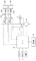
図3に示すように、空気室11UPR,11LWRの給排気口13UPR,13LWRは、それぞれ、電磁制御弁VUPR,VLWRを介して圧力源としての電動ポンプ30に接続されている。電動ポンプ30の吐出側の通路には、圧力源側の排気用として電磁制御弁Vsが介装されている。給排気用の電磁制御弁VUPR,VLWR、圧力源側排気用の電磁制御弁Vs、及び電動ポンプ30は、上下の空気室11UPR,11LWRの内部の圧力を調整する内圧調整装置としての電子制御装置(ECU)50によって駆動制御される。
As shown in FIG. 3, the air supply / exhaust ports 13UPR and 13LWR of the air chambers 11UPR and 11LWR are connected to an
ECU50は、マイクロコンピュータを中心として構成され、ドアの開閉によってON,OFFするドアスイッチ15,ドアガラスを昇降させるためのパワーウィンドウスイッチ(PWスイッチ)16、ウェザーストリップ10の各空気室11UPR,11LWR内の圧力を検出する圧力センサ17UPR,17LWR、電動ポンプ30の吐出側の圧力を検出する圧力センサ18からの信号が入力される。ECU50は、これらのスイッチ・センサ類からの信号、及び、CAN(Controller Area Network)等の車内ネットワークを介して入力される車両の車速Vのデータに基づいて、ウェザーストリップ10の各空気室11UPR,11LWRの内圧を最適に調整する。
The ECU 50 is configured with a microcomputer at the center. The
尚、ECU50には、表示装置60が接続され、内圧調整中の異常を検出した場合等にドライバに情報を提示する。また、図3においては、1つのドアのウェザーストリップに対する空気制御系を示しているが、電磁制御弁VUPR,VLWR、ドアスイッチ15,圧力センサ17UPR,17LWRは、ドアの数に対応して設けられている。
Note that the
ECU50による空気室11UPR,11LWRの内圧調整は、基本的に、上側の空気室11UPRの内圧よりも下側の空気室11LWRの内圧が相対的に高くなるように制御する。すなわち、上側の空気室11UPRの内圧よりも下側の空気室11LWRの内圧を高くすることで、図4に示すように、パネル部側に車体外方に向かう力Foutを発生させ、ドア20のヒンジ部21,21を支点として、相対的にサッシ部を車体側に押圧するような力Finによるモーメントを発生させる。これにより、相対的に強度が低いサッシ部周辺の車体外部方向への変形を防止し、ドアに対する密閉性を向上すると共にルーフ廻りの段差発生による風切り音の発生を低減することができる。
The internal pressure adjustment of the air chambers 11UPR and 11LWR by the
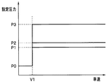
詳細には、ECU50は、ドアが全閉で且つ車速Vが設定車速V1以上であることを検出したとき、上側の空気室11UPRの圧力が設定圧力P1となり、下側の空気室11LWRの圧力が設定圧力P2となるように、電磁制御弁VUPR,VLWRを介して制御する。設定圧力P1,P2は、図5に示すように、P1<P2の関係に設定されており、本実施の形態においては、設定車速V1以上で一定の値に設定されている。より緻密には、設定圧力P1,P2は、ドア位置や車速域によって異なる値に設定しても良い。
Specifically, when the
尚、図5において、設定圧力P0は、上下の空気室11UPR,11LWRを排気して内圧を低下させ、ドアの開閉を容易にするための圧力であり、大気圧相当の圧力を示している。また、設定圧力P3は、空気圧系の安全を確保するための圧力であり、電動ポンプ30の吐出側の許容圧力を示している。
In FIG. 5, the set pressure P0 is a pressure for exhausting the upper and lower air chambers 11UPR and 11LWR to reduce the internal pressure and facilitating opening and closing of the door, and indicates a pressure corresponding to the atmospheric pressure. The set pressure P3 is a pressure for ensuring the safety of the pneumatic system, and indicates the allowable pressure on the discharge side of the
以下、ECU50による空気室11UPR,11LWRの内圧調整処理について、図6に示すフローチャートを用いて説明する。
Hereinafter, the internal pressure adjustment processing of the air chambers 11UPR and 11LWR by the
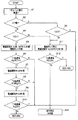
この内圧調整処理では、最初のステップS1において、ドアスイッチ15からの信号及び車速Vのデータを読み込み、ステップS2でドアスイッチ15の信号からドアが開いている(スイッチON)か否かを調べる。そして、ドアスイッチ15がONでドアが開いている場合には、ステップS2からステップS3へ進んで車速Vが設定車速V1以上か否かを調べる。V<V1の場合、ステップS3からステップS11へ進んで、空気室11UPR,11LWRの排気処理(後述)を行ってドアを閉じ易くする。V≧V1の場合には、ドアが閉まっていない状態で走行していると判断して本制御を中止すべくステップS3からステップS20へ進んで異常判定を行い、表示装置60に車両停止を促す警告表示を行ったり警報音を発する等の処置を行う。
In this internal pressure adjustment process, in the first step S1, the signal from the
一方、ステップS2において、ドアスイッチ15がOFFであり、ドアが閉まっている場合には、ステップS2からステップS4へ進み、車速Vが設定車速V1以上か否かを調べる。そして、V≧V1の場合、ステップS5以降で、ドアの密閉性を高めるための空気室11UPR,11LWRの増圧処理を行い、V<V1の場合、ステップS11以降で、ドアの開閉を容易とするための空気室11UPR,11LWRの排気処理を行う。
On the other hand, if the
ここでは、先ず、ステップS5以降の空気室11UPR,11LWRの増圧処理について説明する。ステップS5では、排気用の電磁制御弁Vsを閉弁させて電磁制御弁VUPR,VLWRを開弁させ、上下の空気室11UPR,11LWRを電動ポンプ30の吐出側に連通させた状態で電動ポンプ30を作動させる。
Here, first, the pressure increasing process of the air chambers 11UPR and 11LWR after step S5 will be described. In step S5, the electromagnetic control valve Vs for exhaust is closed to open the electromagnetic control valves VUPR and VLWR, and the
その後、ステップS6で、電動ポンプ30を作動させてから所定の圧力制御時間T1が経過した後、圧力センサ17UPRで検出した上側の空気室11UPRの圧力PUPRを読み込み、この圧力PUPRが設定圧力P1以上か否かを調べる。圧力制御時間T1は、正常に設定圧力に達するまでの許容時間であり、電動ポンプ30の能力、空気経路の配管長さや配管径、空気室の容積等を考慮して設定される。後述する圧力制御時間T2〜T5についても同様である。
Thereafter, in step S6, after a predetermined pressure control time T1 has elapsed since the
ステップS6においてPUPR<P1であり、圧力制御時間T1が経過した後も上側の空気室11UPRの内圧が設定圧力P1まで上昇しない場合には、経路中に漏れの箇所がある等で圧力が上昇しないと判断し、ステップS20で異常判定及び処置を行う。一方、ステップS6においてPUPR≧P1で上側の空気室11UPRの内圧が設定圧力P1に達した場合には、ステップS6からステップS7へ進んで電磁制御弁VUPRを閉弁させ、上側の空気室11UPRを密閉する。 If PUPR <P1 in step S6 and the internal pressure of the upper air chamber 11UPR does not increase to the set pressure P1 even after the pressure control time T1 has elapsed, the pressure does not increase due to a leaking point in the path. In step S20, abnormality determination and treatment are performed. On the other hand, if PUPR ≧ P1 in step S6 and the internal pressure of the upper air chamber 11UPR reaches the set pressure P1, the process proceeds from step S6 to step S7 to close the electromagnetic control valve VUPR, and the upper air chamber 11UPR is closed. Seal.
次いで、ステップS7からステップS8へ進み、圧力制御時間T2が経過した後の下側の空気室11LWRの圧力PLWRを圧力センサ17LWRから読み込み、この圧力PLWRが設定圧力P2以上か否かを調べる。設定圧力P2は、上側の空気室11UPRに対する設定圧力P1よりも高い圧力に設定されている。 Next, the process proceeds from step S7 to step S8, and the pressure PLWR of the lower air chamber 11LWR after the pressure control time T2 has elapsed is read from the pressure sensor 17LWR, and it is checked whether the pressure PLWR is equal to or higher than the set pressure P2. The set pressure P2 is set to a pressure higher than the set pressure P1 for the upper air chamber 11UPR.
ステップS8において、PLWR<P2の場合には、同様に、経路中に漏れの箇所がある等で圧力が上昇しないと判断し、ステップS20で異常判定及び及び処置を行う。一方、PLWR≧P2で下側の空気室11LWRの内圧が設定圧力P2に達した場合には、ステップS8からステップS9へ進んで電磁制御弁VLWRを閉弁させて下側の空気室11LWRを密閉状態として、電動ポンプ30を停止させる。
If PLWR <P2 in step S8, similarly, it is determined that the pressure does not increase due to the presence of a leakage point in the path, and abnormality determination and treatment are performed in step S20. On the other hand, when PLWR ≧ P2 and the internal pressure of the lower air chamber 11LWR reaches the set pressure P2, the process proceeds from step S8 to step S9 to close the electromagnetic control valve VLWR and seal the lower air chamber 11LWR. As a state, the
その後、ステップS10へ進み、圧力制御時間T3が経過した後の電動ポンプ30の吐出側の圧力Psを圧力センサ18から読み込み、圧力Psが設定圧力P3以上に上昇したか否かを調べる。設定圧力P3は、電動ポンプ30による圧力源側の許容圧力であり、Ps≧P3になった場合、ステップS20で異常と判定して異常処置を行い、Ps<P3の場合には、増圧処理が正常に実行されたと判断して本処理を抜ける。
Thereafter, the process proceeds to step S10, and the pressure Ps on the discharge side of the
次に、ステップS11以降の空気室11UPR,11LWRの排気処理について説明する。 Next, the exhaust processing of the air chambers 11UPR and 11LWR after step S11 will be described.
ステップS11では、電動ポンプ30を停止させた状態で、上下の空気室11UPR,11LWRの電磁制御弁VUPR,VLWR、及び排気用の電磁制御弁Vsを開弁させる。そして、ステップS12で、所定の圧力制御時間T4が経過した後、電動ポンプ30の吐出側の圧力Psを圧力センサ18から読み込み、圧力Psが大気圧相当の設定圧力P0以上か否かを調べる。
In step S11, the electromagnetic control valves VUPR and VLWR and the exhaust electromagnetic control valve Vs of the upper and lower air chambers 11UPR and 11LWR are opened while the
その結果、ステップS12でPs>P0であり、圧力制御時間T4が経過した後も電動ポンプ30の吐出側の圧力が大気圧相当の設定圧力P0より低下しない場合には、ステップS20で異常と判定して異常処置を行い、Ps≦P0の場合には、排気処理が正常に実行されたと判断して本処理を抜ける。
As a result, if Ps> P0 in step S12 and the pressure on the discharge side of the
このように本実施の形態においては、ドア全閉且つ設定車速の条件下でウェザーストリップ10の上側の空気室11UPRの圧力よりも下側の空気室11LWRの圧力の方が高くなるように調整するため、相対的に強度が低いドアサッシ部周辺の車体外部方向への変形を防止して密閉性を向上すると共に、ルーフ廻りの段差発生による風切り音の発生を低減することができる。
As described above, in the present embodiment, the pressure in the lower air chamber 11LWR is adjusted to be higher than the pressure in the upper air chamber 11UPR of the
次に、本発明の実施の第2形態について説明する。
第2形態は、サッシレスのドアに対応して、ウェザーストリップ10の上下の空気室11UPR,11LWRの内圧調整処理の一部を変更するものであり、第1形態の内圧調整処理(図6参照)に対して、サッシレスドアのドアガラスの昇降状態に応じた処理を追加する。
Next, a second embodiment of the present invention will be described.
The second form changes part of the internal pressure adjustment process of the upper and lower air chambers 11UPR and 11LWR of the
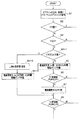
第2形態の内圧調整処理の第1形態と異なる処理は、図7の要部フローチャートに示される。この要部フローチャートに示す処理では、第1形態の最初のステップS1を若干変更した最初のステップS1’において、ドアスイッチ15からの信号及び車速Vのデータに加え、ドアガラスの昇降状態を検出するためパワーウィンドウスイッチ16からの信号を読み込む。そして、第1形態と同様、ステップS2でドアスイッチ15の信号からドアが開いている(スイッチON)か否かを調べる。
The process different from the first form of the internal pressure adjustment process of the second form is shown in the main part flowchart of FIG. In the process shown in the main part flowchart, in the first step S1 ′ obtained by slightly changing the first step S1 of the first embodiment, the raising / lowering state of the door glass is detected in addition to the signal from the
ドアスイッチ15がON(ドア開)である場合は、第1形態と同様であり、車速に応じて排気処理や異常処理を行う。一方、ドアスイッチ15がOFF(ドア閉)の場合、ステップS4で車速Vが設定車速V1以上か否かを調べ、V<V1の場合、第1形態と同様、ステップS11以降で排気処理を行い、V≧V1の場合、ステップS5以降の増圧処理を行う前に、ステップS4−1の処理を実行する。
When the
このステップS4−1の処理は、パワーウィンドウスイッチ16の信号からドアガラスの昇降状態を判断する処理であり。ここでは、パワーウィンドウスイッチ16のダウン側の信号からドアガラスが下降しているか否かを調べる。その結果、パワーウィンドウスイッチ16のダウン側の信号がOFFでドアガラスが下降していない場合には、ステップS4−1からステップS5へ進み、第1形態と同様、上下の空気室11UPR,11LWRに対する増圧処理を行う。
The process of step S4-1 is a process of determining the raising / lowering state of the door glass from the signal of the
一方、パワーウィンドウスイッチ16のダウン側の信号がONでドアガラスが下降している場合には、ステップS4−1からステップS4−2へ進み、下側の空気室11LWRの電磁制御弁VLWRを閉弁させた状態で、上側の空気室11UPRの電磁制御弁VUPRと排気用の電磁制御弁Vsとを開弁させ、上側の空気室11UPRを排気して所定の設定圧力に低下させる。
On the other hand, when the signal on the down side of the
尚、このときの上側の空気室11UPRを低下させる設定圧力は、簡易的には大気圧に近い圧力とするが、より精密には、ドアガラス昇降システムからドアガラスの昇降位置に係る情報を取得し、この位置情報に基づいて、ステップS4−1でドアガラスの開閉状態を調べ、ドアガラスが開いているとき、空気室11UPRの圧力を低下させる際の設定圧力をガラス位置に応じて可変するようにしても良い。また、このとき、空気室11UPRの内圧が正常に低下するか否かを調べる異常判定処理を追加するようにしても良い。 Note that the set pressure for lowering the upper air chamber 11UPR at this time is simply a pressure close to atmospheric pressure, but more precisely, information related to the lift position of the door glass is acquired from the door glass lift system. Then, based on this position information, the open / close state of the door glass is checked in step S4-1, and when the door glass is open, the set pressure for reducing the pressure of the air chamber 11UPR is varied according to the glass position. You may do it. At this time, an abnormality determination process for checking whether or not the internal pressure of the air chamber 11UPR is normally reduced may be added.
次に、ステップS4−2からステップS4−3ヘ進み、所定の圧力制御時間T5が経過した後に、上側の空気室11UPRの電磁制御弁VUPRと排気用の電磁制御弁Vsとを閉弁させて、下側の空気室11LWRの電磁制御弁VLWRを開弁させ、電動ポンプ30を作動させる。その後、ステップS4−3からステップS8へ進み、第1形態と同様の処理を行う。但し、ステップS4−3からステップS8へ進む場合には、圧力制御時間T2は、ステップS7からステップS8に進む場合よりも長くする。
Next, the process proceeds from step S4-2 to step S4-3, and after a predetermined pressure control time T5 has elapsed, the electromagnetic control valve VUPR and the exhaust electromagnetic control valve Vs of the upper air chamber 11UPR are closed. Then, the electromagnetic control valve VLWR of the lower air chamber 11LWR is opened, and the
このように、第2形態においては、サッシレスドアのドアガラスが開いている状態では、上側の空気室11UPR内を排気して圧力を低下させることにより、上側の空気室11UPRの不要な内圧を無くしてドアガラスに過剰な力がかかることを防止することができる。 Thus, in the second embodiment, in the state where the door glass of the sashless door is open, unnecessary pressure inside the upper air chamber 11UPR is reduced by exhausting the inside of the upper air chamber 11UPR to reduce the pressure. It can be prevented that excessive force is applied to the door glass.
1 ボディ
10 ウェザーストリップ
11UPR,11LWR 空気室
12 隔壁
13UPR,13LWR 給排気口
20 ドア
30 電動ポンプ
50 電子制御装置
VUPR,VLWR 電磁制御弁
V1 設定車速
P1,P2 設定圧力
1
Claims (3)
複数の独立した空気室を有し、各空気室に空気の給排気口を備えた前記ウェザーストリップと、
前記ウェザーストリップの各空気室の給排気口と圧力発生源との間に介装され、前記各空気室への空気の供給及び排気を制御する制御弁と、
ドア全閉且つ設定車速以上のとき、ドアガラス部に対応する部位の前記空気室の圧力よりもドアパネル部に対応する前記空気室の圧力が高くなるように前記制御弁を介して調整する内圧調整装置と
を備えることを特徴とする車両のドアシール装置。 A vehicle door seal device that seals between a vehicle body and a door via a weatherstrip,
The weather strip having a plurality of independent air chambers, each air chamber having an air supply / exhaust port;
A control valve that is interposed between a supply / exhaust port of each air chamber of the weather strip and a pressure generation source and controls supply and exhaust of air to each air chamber;
When the door is fully closed and above the set vehicle speed, the internal pressure adjustment is adjusted via the control valve so that the pressure of the air chamber corresponding to the door panel portion is higher than the pressure of the air chamber of the portion corresponding to the door glass portion. A vehicle door seal device.
前記内圧調整装置は、前記上側の空気室の圧力よりも前記下側の空気室の圧力が高くなるように調整することを特徴とする請求項1記載の車両のドアシール装置。 The weather strip has two upper and lower air chambers, an upper air chamber corresponding to the door glass portion and a lower air chamber corresponding to the door panel portion,
2. The vehicle door seal device according to claim 1, wherein the internal pressure adjusting device adjusts the pressure of the lower air chamber to be higher than the pressure of the upper air chamber.
Priority Applications (1)
| Application Number | Priority Date | Filing Date | Title |
|---|---|---|---|
| JP2013053957A JP6076155B2 (en) | 2013-03-15 | 2013-03-15 | Vehicle door seal device |
Applications Claiming Priority (1)
| Application Number | Priority Date | Filing Date | Title |
|---|---|---|---|
| JP2013053957A JP6076155B2 (en) | 2013-03-15 | 2013-03-15 | Vehicle door seal device |
Publications (2)
| Publication Number | Publication Date |
|---|---|
| JP2014177247A true JP2014177247A (en) | 2014-09-25 |
| JP6076155B2 JP6076155B2 (en) | 2017-02-08 |
Family
ID=51697637
Family Applications (1)
| Application Number | Title | Priority Date | Filing Date |
|---|---|---|---|
| JP2013053957A Active JP6076155B2 (en) | 2013-03-15 | 2013-03-15 | Vehicle door seal device |
Country Status (1)
| Country | Link |
|---|---|
| JP (1) | JP6076155B2 (en) |
Cited By (1)
| Publication number | Priority date | Publication date | Assignee | Title |
|---|---|---|---|---|
| CN110774875A (en) * | 2019-11-01 | 2020-02-11 | 天津捷强动力装备股份有限公司 | High-overpressure type collective protection system |
Citations (5)
| Publication number | Priority date | Publication date | Assignee | Title |
|---|---|---|---|---|
| JPS6042136A (en) * | 1983-08-19 | 1985-03-06 | Nissan Motor Co Ltd | Weather strip |
| JPS61117718U (en) * | 1985-01-10 | 1986-07-25 | ||
| JPH0331027A (en) * | 1989-06-28 | 1991-02-08 | Toyoda Gosei Co Ltd | Vehicle weather strip |
| JPH05270277A (en) * | 1992-03-24 | 1993-10-19 | Kurashiki Kako Co Ltd | Glass-run for automobile |
| JPH09207571A (en) * | 1996-01-31 | 1997-08-12 | Yazaki Corp | Door weather strip structure |
-
2013
- 2013-03-15 JP JP2013053957A patent/JP6076155B2/en active Active
Patent Citations (5)
| Publication number | Priority date | Publication date | Assignee | Title |
|---|---|---|---|---|
| JPS6042136A (en) * | 1983-08-19 | 1985-03-06 | Nissan Motor Co Ltd | Weather strip |
| JPS61117718U (en) * | 1985-01-10 | 1986-07-25 | ||
| JPH0331027A (en) * | 1989-06-28 | 1991-02-08 | Toyoda Gosei Co Ltd | Vehicle weather strip |
| JPH05270277A (en) * | 1992-03-24 | 1993-10-19 | Kurashiki Kako Co Ltd | Glass-run for automobile |
| JPH09207571A (en) * | 1996-01-31 | 1997-08-12 | Yazaki Corp | Door weather strip structure |
Cited By (1)
| Publication number | Priority date | Publication date | Assignee | Title |
|---|---|---|---|---|
| CN110774875A (en) * | 2019-11-01 | 2020-02-11 | 天津捷强动力装备股份有限公司 | High-overpressure type collective protection system |
Also Published As
| Publication number | Publication date |
|---|---|
| JP6076155B2 (en) | 2017-02-08 |
Similar Documents
| Publication | Publication Date | Title |
|---|---|---|
| US10696147B2 (en) | Pressurized sealing systems for vehicle closure members | |
| CN100487610C (en) | Control apparatus and method for opening and closing tailgate using angular sensor | |
| US8555552B2 (en) | Inflatable door seal | |
| US9931900B2 (en) | Air suspension system | |
| CN205908217U (en) | Novel aerify sealed door | |
| CN110656842A (en) | Device capable of reducing closing force and ear pressure of car door and car | |
| JP6076155B2 (en) | Vehicle door seal device | |
| US7972204B2 (en) | Vehicle door seal venting system and method | |
| KR101230904B1 (en) | Control apparatus and method for side door glass when tailgate opens and closes | |
| CN109177704A (en) | A kind of the bus door sealing strip and sealing adjusting method of double cavity structure | |
| JP6687883B2 (en) | Electric vehicle insulation structure | |
| KR20120107164A (en) | Room pressure adjusting system for vehicle | |
| CN111779848B (en) | Pressure relief device and vehicle with same | |
| CN112498063A (en) | Vehicle and vehicle control method | |
| CN211038287U (en) | Device capable of reducing closing force and ear pressure of car door and car | |
| KR100897326B1 (en) | Sealing apparatus of door glass for vehicle | |
| KR101966527B1 (en) | Weather strip for door of vehicle having variable cross-section | |
| CN208789465U (en) | A kind of bus door sealing strip of double cavity structure | |
| KR20060013756A (en) | Gas lifter internal pressure control method using an angle sensor | |
| JP4962347B2 (en) | Control method for raising and lowering window glass for automobiles | |
| JP6785085B2 (en) | Open / close control device | |
| JP2015081068A (en) | Collision detection device and failure detection method thereof | |
| KR20230073833A (en) | Pressure variable type weather strip | |
| CN214775313U (en) | Vehicle with a steering wheel | |
| KR101188473B1 (en) | Apparatus for controlling air extractor of varible and method thereof |
Legal Events
| Date | Code | Title | Description |
|---|---|---|---|
| A621 | Written request for application examination |
Free format text: JAPANESE INTERMEDIATE CODE: A621 Effective date: 20151225 |
|
| A977 | Report on retrieval |
Free format text: JAPANESE INTERMEDIATE CODE: A971007 Effective date: 20160908 |
|
| A131 | Notification of reasons for refusal |
Free format text: JAPANESE INTERMEDIATE CODE: A131 Effective date: 20160913 |
|
| A521 | Request for written amendment filed |
Free format text: JAPANESE INTERMEDIATE CODE: A523 Effective date: 20161104 |
|
| TRDD | Decision of grant or rejection written | ||
| A01 | Written decision to grant a patent or to grant a registration (utility model) |
Free format text: JAPANESE INTERMEDIATE CODE: A01 Effective date: 20161213 |
|
| A61 | First payment of annual fees (during grant procedure) |
Free format text: JAPANESE INTERMEDIATE CODE: A61 Effective date: 20170110 |
|
| R150 | Certificate of patent or registration of utility model |
Ref document number: 6076155 Country of ref document: JP Free format text: JAPANESE INTERMEDIATE CODE: R150 |
|
| S533 | Written request for registration of change of name |
Free format text: JAPANESE INTERMEDIATE CODE: R313533 |
|
| R350 | Written notification of registration of transfer |
Free format text: JAPANESE INTERMEDIATE CODE: R350 |
|
| R250 | Receipt of annual fees |
Free format text: JAPANESE INTERMEDIATE CODE: R250 |
|
| R250 | Receipt of annual fees |
Free format text: JAPANESE INTERMEDIATE CODE: R250 |
|
| R250 | Receipt of annual fees |
Free format text: JAPANESE INTERMEDIATE CODE: R250 |
|
| R250 | Receipt of annual fees |
Free format text: JAPANESE INTERMEDIATE CODE: R250 |
|
| R250 | Receipt of annual fees |
Free format text: JAPANESE INTERMEDIATE CODE: R250 |