JP2014175253A - Lighting device - Google Patents

Lighting device Download PDF

Info

Publication number
JP2014175253A
JP2014175253A JP2013049396A JP2013049396A JP2014175253A JP 2014175253 A JP2014175253 A JP 2014175253A JP 2013049396 A JP2013049396 A JP 2013049396A JP 2013049396 A JP2013049396 A JP 2013049396A JP 2014175253 A JP2014175253 A JP 2014175253A
Authority
JP
Japan
Prior art keywords
light
optical sheet
sheet
optical
light emitting
Prior art date
Legal status (The legal status is an assumption and is not a legal conclusion. Google has not performed a legal analysis and makes no representation as to the accuracy of the status listed.)
Pending
Application number
JP2013049396A
Other languages
Japanese (ja)
Inventor
Eiji Asano
野 英 司 浅
Current Assignee (The listed assignees may be inaccurate. Google has not performed a legal analysis and makes no representation or warranty as to the accuracy of the list.)
Dai Nippon Printing Co Ltd
Original Assignee
Dai Nippon Printing Co Ltd
Priority date (The priority date is an assumption and is not a legal conclusion. Google has not performed a legal analysis and makes no representation as to the accuracy of the date listed.)
Filing date
Publication date
Application filed by Dai Nippon Printing Co Ltd filed Critical Dai Nippon Printing Co Ltd
Priority to JP2013049396A priority Critical patent/JP2014175253A/en
Publication of JP2014175253A publication Critical patent/JP2014175253A/en
Pending legal-status Critical Current

Links

Images

Landscapes

  • Optical Elements Other Than Lenses (AREA)
  • Planar Illumination Modules (AREA)

Abstract

PROBLEM TO BE SOLVED: To provide a lighting device in which a light source is discreet and whose weight is light.SOLUTION: A lighting device 10 includes an optical sheet having a sheet-like main body 35 and a plurality of unit optical elements 40 arranged on one surface 35b of the main body, and a light source 20 for projecting light from one side to the other side in the first direction din parallel with an arrangement direction of the unit optical element. The optical sheet includes a light dispersion layer 31 having a dispersion component 31b and a non-light dispersion layer 32 where the dispersion component is not dispersed. The unit optical element is included in the non-light dispersion layer. The light source has one or more light-emitting members 25. Each of the light emitting members is arranged in such a way that its light axis pd may face to a position on the surface where the unit optical element of the optical sheet and at least a part of the light emitted by each of the light emitting members is directly incident to the optical sheet.

Description

本発明は、照明装置に係り、とりわけ、光源が目立たなく且つ軽量化された照明装置に関する。   The present invention relates to an illuminating device, and more particularly, to an illuminating device in which a light source is inconspicuous and reduced in weight.

従来、種々の照明装置が開発されてきた。照明装置は、大別すると、光学部材の直下に光源を配置する直下型と、例えば特許文献1に開示されているように光学部材の側方に光源を配置するエッジライト型(サイドライト型とも呼ぶ)と、に分類される。このうち、サイドライト型(エッジライト型)の照明装置では、典型的には、導光板と、導光板の側方に配置された光源と、導光板の出光側に配置された光制御シートと、を有している。導光板は、導光方向における光量の分布を調整し、光制御シートは、導光板から出射した光の進行方向を調整する。   Conventionally, various lighting devices have been developed. The illuminating device can be broadly divided into a direct type in which a light source is arranged directly under the optical member, and an edge light type in which a light source is arranged on the side of the optical member as disclosed in Patent Document 1 (both side light type). Called). Among these, in a sidelight type (edge light type) lighting device, typically, a light guide plate, a light source disposed on the side of the light guide plate, and a light control sheet disposed on the light output side of the light guide plate, ,have. The light guide plate adjusts the light amount distribution in the light guide direction, and the light control sheet adjusts the traveling direction of the light emitted from the light guide plate.

特開平6−160642号公報JP-A-6-160642

ところで、直下型の照明装置では、光源の像が視認されるようになる、すなわち、光源の配列に応じた明るさのむらが目立ってしまい、意匠面において好ましくない。この明るさのむらを不可視化するためには強い光拡散機能を有した拡散板を用いる必要が生じるが、この場合、光源からの光の利用効率が大きく低下してしまう。   By the way, in the direct type illumination device, an image of the light source is visually recognized, that is, uneven brightness depending on the arrangement of the light sources is conspicuous, which is not preferable in terms of design. In order to make this uneven brightness invisible, it is necessary to use a diffusion plate having a strong light diffusion function, but in this case, the utilization efficiency of light from the light source is greatly reduced.

一方、サイドライト型の照明装置では、光源からの光を導光する導光板の厚みが厚くなってしまい、照明装置が重量化してしまう。このため、サイドライト型照明装置において、発光面を大型化することが困難となる。さらに、特許文献1に開示された照明装置では、導光板に形成された印刷パターンが視認されてしまい、意匠性が害される。   On the other hand, in the sidelight type illumination device, the thickness of the light guide plate that guides light from the light source is increased, and the illumination device becomes heavy. For this reason, in the sidelight type illumination device, it is difficult to increase the size of the light emitting surface. Furthermore, in the illuminating device disclosed in Patent Document 1, the printed pattern formed on the light guide plate is visually recognized, and the design is impaired.

本発明は、以上の点を考慮してなされたものであり、光源が目立たなく且つ軽量化された照明装置を提供することを目的とする。   The present invention has been made in consideration of the above points, and an object of the present invention is to provide an illumination device in which a light source is not conspicuous and is reduced in weight.

本発明による照明装置は、
シート状の本体部と、前記本体部の一方の面上に配列された複数の単位光学要素と、を有する光学シートと、
前記単位光学要素の配列方向と平行な第1方向において一側から他側へ向かうように光を投射する光源と、を備え、
前記光学シートは、拡散成分を有する光拡散層と、前記拡散成分が分散されていない非光拡散層と、を含み、前記単位光学要素は、前記非光拡散層に含まれ、
前記光源は、一以上の発光部材を有し、
各発光部材は、その光軸が前記光学シートの前記単位光学要素が設けられている面上の位置へ向くように配置され、各発光部材で発光された光の少なくとも一部が前記光学シートへ直接入射する。
The lighting device according to the present invention comprises:
An optical sheet having a sheet-like main body, and a plurality of unit optical elements arranged on one surface of the main body,
A light source that projects light from one side to the other side in a first direction parallel to the arrangement direction of the unit optical elements,
The optical sheet includes a light diffusion layer having a diffusion component and a non-light diffusion layer in which the diffusion component is not dispersed, and the unit optical element is included in the non-light diffusion layer,
The light source has one or more light emitting members,
Each light emitting member is disposed such that its optical axis is directed to a position on the surface of the optical sheet where the unit optical element is provided, and at least a part of the light emitted by each light emitting member is directed to the optical sheet. Directly incident.

本発明による照明装置において、前記光学シートの各単位光学要素は、前記単位光学要素の配列方向と交差する方向に線状に延びていてもよい。   In the illumination device according to the present invention, each unit optical element of the optical sheet may extend linearly in a direction intersecting with the arrangement direction of the unit optical elements.

本発明による照明装置において、前記発光部材は、前記光学シートの法線方向に沿って前記光学シートに対面する位置から、前記光学シートのシート面に沿ってずれた位置に配置されていてもよい。   In the illumination device according to the present invention, the light emitting member may be disposed at a position shifted along a sheet surface of the optical sheet from a position facing the optical sheet along a normal direction of the optical sheet. .

本発明による照明装置は、前記第1方向において前記他側から一側へ向かうように光を投射する第2光源を、さらに備え、
前記第2光源は、一以上の発光部材を有し、
前記第2光源の各発光部材は、その光軸が前記光学シートの前記単位光学要素が設けられている面上の位置へ向くように配置され、前記第2光源の各発光部材で発光された光の少なくとも一部が前記光学シートへ直接入射するようにしてもよい。
The illumination device according to the present invention further includes a second light source that projects light so as to go from the other side to the one side in the first direction,
The second light source has one or more light emitting members,
Each light emitting member of the second light source is disposed so that its optical axis is directed to a position on the surface of the optical sheet where the unit optical element is provided, and light is emitted from each light emitting member of the second light source. At least a part of the light may be directly incident on the optical sheet.

本発明による照明装置において、前記第2光源の前記発光部材は、前記光学シートの法線方向に沿って前記光学シートに対面する位置から、前記光学シートのシート面に沿ってずれた位置に配置されていてもよい。   In the illumination device according to the present invention, the light emitting member of the second light source is disposed at a position shifted along a sheet surface of the optical sheet from a position facing the optical sheet along a normal direction of the optical sheet. May be.

本発明による照明装置において、前記光学シートの前記単位光学要素が設けられている側とは反対側面での輝度を、前記光学シートへの法線方向および前記第1方向の両方向に沿った面内の各方向から、測定することによって得られる輝度の角度分布において、前記光学シートへの法線方向の両側となる方向に、前記光学シートの法線方向での輝度よりも高輝度となる輝度のピークが存在するようにしてもよい。   In the illuminating device according to the present invention, the luminance of the side surface of the optical sheet opposite to the side on which the unit optical element is provided is determined to be in-plane along both the normal direction to the optical sheet and the first direction. In the angular distribution of luminance obtained by measuring from each of the directions of the brightness of the brightness that is higher than the brightness in the normal direction of the optical sheet in the direction on both sides of the normal direction to the optical sheet A peak may be present.

本発明による照明装置において、前記ピークが生じる方向は、前記光学シートの法線方向から20°以上ずれていてもよい。   In the illuminating device according to the present invention, the direction in which the peak occurs may be shifted by 20 ° or more from the normal direction of the optical sheet.

本発明による照明装置において、前記光学シートへの法線方向および前記第1方向の両方向に沿った断面における、前記第1方向に沿った前記光学シートの両端間の長さAと、前記光学シートの法線方向に沿った前記光学シートから前記発光部材までの長さBと、前記単位光学要素の前記第1方向に沿った幅wと、前記光学シートの法線方向に沿った前記単位光学要素の高さhと、が次の関係を満たすようにしてもよい。
0.5<h/w<1.5
0.025<B/A<0.25
In the illumination device according to the present invention, a length A between both ends of the optical sheet along the first direction in a cross section along both the normal direction to the optical sheet and the first direction, and the optical sheet A length B from the optical sheet to the light-emitting member along the normal direction of the optical axis, a width w along the first direction of the unit optical element, and the unit optics along the normal direction of the optical sheet The height h of the element may satisfy the following relationship.
0.5 <h / w <1.5
0.025 <B / A <0.25

本発明による照明装置において、前記光学シートは一体的に形成された厚み1.0mm以上のシートであるようにしてもよい。   In the illumination device according to the present invention, the optical sheet may be an integrally formed sheet having a thickness of 1.0 mm or more.

本発明によれば、照明装置において光源の像を十分に目立たなくすることができ、且つ、照明装置を軽量化することができる。   ADVANTAGE OF THE INVENTION According to this invention, the image of a light source can be made not conspicuous enough in an illuminating device, and a illuminating device can be reduced in weight.

図1は、本発明による一実施の形態を説明するための図であって、照明装置を模式的に示す図である。FIG. 1 is a diagram for explaining an embodiment according to the present invention, and schematically shows a lighting device. 図2は、図1の照明装置を示す縦断面図である。FIG. 2 is a longitudinal sectional view showing the illumination device of FIG. 図3は、図1の照明装置の一部分を示す斜視図である。FIG. 3 is a perspective view showing a part of the illumination device of FIG. 図4は、図1の照明装置の発光面上の輝度の角度分布を示すグラフである。FIG. 4 is a graph showing the angular distribution of luminance on the light emitting surface of the illumination device of FIG. 図5は、光学シートの製造方法の一例を説明するための図である。FIG. 5 is a diagram for explaining an example of a method for manufacturing an optical sheet. 図6は、照明装置の一変形例を示す縦断面図である。FIG. 6 is a longitudinal sectional view showing a modification of the lighting device.

以下、図面を参照して本発明の一実施の形態について説明する。なお、本件明細書に添付する図面においては、図示と理解のしやすさの便宜上、適宜縮尺および縦横の寸法比等を、実物のそれらから変更し誇張してある。   Hereinafter, an embodiment of the present invention will be described with reference to the drawings. In the drawings attached to the present specification, for the sake of illustration and ease of understanding, the scale, the vertical / horizontal dimension ratio, and the like are appropriately changed and exaggerated from those of the actual product.

本明細書において、「シート」、「板」、「フィルム」の用語は、呼称の違いのみに基づいて、互いから区別されるものではない。例えば、「シート」は板やフィルムと呼ばれ得るような部材も含む概念であり、したがって、例えば「光学シート」は、「光学板」や「光学フィルム」と呼ばれる部材と呼称の違いのみにおいて区別され得ない。   In this specification, the terms “sheet”, “plate”, and “film” are not distinguished from each other based only on the difference in designation. For example, “sheet” is a concept that includes a member that can be called a plate or a film. Therefore, for example, “optical sheet” is distinguished from a member called “optical plate” or “optical film” only by a difference in the name. Can't be done.

また、「シート面(板面、フィルム面)」とは、対象となるシート状(板状、フィルム状)の部材を全体的かつ大局的に見た場合において対象となるシート状部材(板状部材、フィルム状部材)の平面方向と一致する面のことを指す。本実施の形態においては、照明装置の発光面および光学シートの板面は平行となっている。また、正面方向とは、光学シートのシート面への法線方向のことを指す。   In addition, “sheet surface (plate surface, film surface)” means a target sheet-like member (plate-like) when the target sheet-like (plate-like, film-like) member is viewed as a whole and globally. It refers to the surface that coincides with the plane direction of the member or film-like member. In the present embodiment, the light emitting surface of the lighting device and the plate surface of the optical sheet are parallel. Also, the front direction refers to the normal direction to the sheet surface of the optical sheet.

さらに、本明細書において用いる、形状や幾何学的条件並びにそれらの程度を特定する、例えば、「平行」、「直交」、「同一」等の用語や長さや角度の値等については、厳密な意味に縛られることなく、同様の機能を期待し得る程度の範囲を含めて解釈することとする。   Furthermore, as used in this specification, the shape and geometric conditions and the degree thereof are specified. For example, terms such as “parallel”, “orthogonal”, “identical”, length and angle values, etc. Without being bound by meaning, it should be interpreted including the extent to which similar functions can be expected.

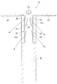
図1〜図5は、本発明の一実施の形態を説明するための図である。このうち、図1は、照明装置10の設置状況を示す図であり、図2は、照明装置10の作用を説明するための図であり、図3は、照明装置10の光学シート30を説明するための図であり、図4は、照明装置10の発光特性を示すグラフであり、図5は、光学シートの製造方法の一例を説明するための図である。照明装置10は、発光面10aを有し、発光面10aから面状に光を発光する。図1に示された例において、照明装置10は、その発光面10aが室内に露出するようにして、天井90に埋め込まれている。   1-5 is a figure for demonstrating one embodiment of this invention. Among these, FIG. 1 is a figure which shows the installation condition of the illuminating device 10, FIG. 2 is a figure for demonstrating an effect | action of the illuminating device 10, and FIG. 3 demonstrates the optical sheet 30 of the illuminating device 10. FIG. FIG. 4 is a graph showing the light emission characteristics of the illumination device 10, and FIG. 5 is a diagram for explaining an example of a method for manufacturing an optical sheet. The illumination device 10 has a light emitting surface 10a and emits light in a planar shape from the light emitting surface 10a. In the example shown in FIG. 1, the lighting device 10 is embedded in the ceiling 90 so that the light emitting surface 10a is exposed indoors.

図1及び図2に示すように、照明装置10は、光学シート30と、光学シート30に光を投射する光源20と、を有している。光学シート30は、光源20からの光を受ける入光側面30bと、室内側(すなわち、被照明領域側)を向いた出光側面30aと、を有している。また、照明装置10は、光学シート30の入光側面30bに対面するようして設けられたケース15を有する。ケース15は、その端部において、光学シート30の側端面の全周に接続するようにして、光学シート30の入光側面30bを覆っている。ケース15の内面は、金属等の高反射率材料からなる反射面として形成されている。   As illustrated in FIGS. 1 and 2, the lighting device 10 includes an optical sheet 30 and a light source 20 that projects light onto the optical sheet 30. The optical sheet 30 has a light incident side surface 30b that receives light from the light source 20, and a light outgoing side surface 30a that faces the indoor side (that is, the illuminated region side). The illumination device 10 includes a case 15 provided so as to face the light incident side surface 30 b of the optical sheet 30. The case 15 covers the light incident side surface 30b of the optical sheet 30 so as to be connected to the entire circumference of the side end surface of the optical sheet 30 at the end thereof. The inner surface of the case 15 is formed as a reflective surface made of a highly reflective material such as metal.

なお、図示された例では、光学シート30は、平面視において四角形形状となるように構成されており、第1方向dに対向する一対の縁部30c1,30c2と、第2方向に対向するもう一対の縁部と、を有している。図3に示すように、図示された例において、第1方向dおよび第2方向dは互いに直交している。 In the example shown, the optical sheet 30 is configured such that a quadrangular shape in plan view, a pair of edge 30c1,30c2 opposite the first direction d 1, opposite to the second direction And another pair of edges. As shown in FIG. 3, in the illustrated example, the first direction d 1 and the second direction d 2 are orthogonal to each other.

図1及び図2に示すように、光源20は、第1方向dに離間した第1光源21及び第2光源22を有している。第1光源21が、光学シート30の第1方向dに対向する一対の縁部のうちの一方30c1の近傍に設けられ、第2光源22が、光学シート30の第1方向dに対向する一対の縁部のうちの他方30c2の近傍に設けられている。そして、第1光源21は、第1方向dにおいて一側から他側へ向かうように光を投射し、第2光源22は、第1方向dにおいて他側から一側へ向かうように光を投射する。 As shown in FIGS. 1 and 2, the light source 20 includes a first light source 21 and a second light source 22 that are separated in the first direction d 1 . The first light source 21 is provided in the vicinity of one of the pair of edges facing the first direction d 1 of the optical sheet 30, and the second light source 22 is opposed to the first direction d 1 of the optical sheet 30. It is provided in the vicinity of the other 30c2 of the pair of edges. The first light source 21, in the first direction d 1 of the light projected to face from one side to the other side, the second light source 22, the light as in the first direction d 1 direction from the other side to the one side Project.

光源20をなす発光部材25として、種々の既知な発光部材25、例えば冷陰極管、とりわけ配光方向を絞った冷陰極管を用いることもできる。ただし、図示する例では、複数の点状発光部材25、典型的には、線状に配列された複数の発光ダイオード(LED)を用いて各光源21,22が構成されている。各光源21,22をなす多数の発光部材25は、対応する縁部30c1,30c2の長手方向に沿って並べて配置されている。すなわち、図3に示すように、本実施の形態では、各光源21,22をなす多数の点状発光部材25は、第2方向dに並べて配置されている。 As the light emitting member 25 constituting the light source 20, various known light emitting members 25, for example, a cold cathode tube, in particular, a cold cathode tube with a narrow light distribution direction can be used. However, in the illustrated example, each of the light sources 21 and 22 is configured using a plurality of point light emitting members 25, typically a plurality of light emitting diodes (LEDs) arranged in a line. A large number of light emitting members 25 constituting the light sources 21 and 22 are arranged side by side along the longitudinal direction of the corresponding edge portions 30c1 and 30c2. That is, as shown in FIG. 3, in the present embodiment, a large number of point light emitting members 25 constituting the light sources 21 and 22 are arranged side by side in the second direction d 2 .

図2及び図3によく示されているように、この照明装置10では、光源21,22をなす発光部材25は、光学シート30のシート面に沿って光学シート30の外輪郭の外方に位置している。より詳細には、一対の光源21,22の発光部材25は、それぞれ、第1方向dに対向する一対の縁部30c1,30c2の両外方となる位置にそれぞれ配置されている。すなわち、平面視において(光学シート30への法線方向ndから観察した場合において)、光源21,22をなす発光部材25は、光学シート30と重ならない位置に配置されている。 As well shown in FIGS. 2 and 3, in the illumination device 10, the light emitting member 25 that constitutes the light sources 21 and 22 extends outward of the outer contour of the optical sheet 30 along the sheet surface of the optical sheet 30. positioned. More specifically, the light emitting member 25 of the pair of light sources 21 and 22, respectively, are arranged on the position where the both outer sides of the pair of edges 30c1,30c2 opposite the first direction d 1. That is, in plan view (when observed from the normal direction nd to the optical sheet 30), the light emitting members 25 that constitute the light sources 21 and 22 are arranged at positions that do not overlap the optical sheet 30.

また、この照明装置10では、図2に示すように、光源21,22をなす発光部材25は、正面方向ndに沿って光学シート30からずれた位置に配置されている。より詳細には、光源21,22をなす発光部材25は、光学シート30の入光側面30bよりも、光学シート30のシート面への法線方向ndに沿って、光学シート30から離間する側(室内から離間する側)へずれた位置に配置されている。このため、図2に示すように、光源21,22をなす発光部材25で発光された光は、指向性を持ち、光学シート30の入光側面30bに直接入射し得るようになっている。   Moreover, in this illuminating device 10, as shown in FIG. 2, the light emitting member 25 which comprises the light sources 21 and 22 is arrange | positioned in the position shifted | deviated from the optical sheet 30 along the front direction nd. More specifically, the light emitting member 25 that constitutes the light sources 21 and 22 is on the side away from the optical sheet 30 along the normal direction nd to the sheet surface of the optical sheet 30 rather than the light incident side surface 30b of the optical sheet 30. It is arranged at a position shifted to the side away from the room. For this reason, as shown in FIG. 2, the light emitted from the light emitting member 25 constituting the light sources 21 and 22 has directivity and can directly enter the light incident side surface 30 b of the optical sheet 30.

ところで、図示された例において、発光部材25は、LEDのような点状の発光体26と、発光体26を覆うように設けられたキャップ27と、を有している。キャップ27は、発光体26で発光される光の進行方向を制御し、発光部材25の配光特性を調整する。すなわち、発光部材25は、光を均一な光度で放射状に発光するのではなく、指向性を有している。発光部材25は、各方向に異なる光度(単位:カンデラ)で光を放射し、特定の方向pdにピーク光度を持つ。そして、当該特定の方向pdに対する傾斜角度が大きくなるにつれて、光度の値はしだいに低下していく。好ましくは、このような発光部材25の指向特性(配光特性、さらに言い換えると、光度の角度(方向)分布)を考慮して、光源20をなす発光部材25の配置が決定される。なお、本明細書では、ピーク光度をもたらす上記特定の方向を「光軸」と呼ぶ。   Incidentally, in the illustrated example, the light emitting member 25 includes a point-like light emitter 26 such as an LED, and a cap 27 provided so as to cover the light emitter 26. The cap 27 controls the traveling direction of light emitted from the light emitter 26 and adjusts the light distribution characteristics of the light emitting member 25. That is, the light emitting member 25 does not emit light radially with a uniform luminous intensity, but has directivity. The light emitting member 25 emits light with a different luminous intensity (unit: candela) in each direction, and has a peak luminous intensity in a specific direction pd. As the inclination angle with respect to the specific direction pd increases, the value of the luminous intensity gradually decreases. Preferably, the arrangement of the light emitting members 25 constituting the light source 20 is determined in consideration of the directivity characteristics (light distribution characteristics, in other words, the angle (direction) distribution of luminous intensity) of the light emitting members 25. In the present specification, the above-described specific direction that provides the peak luminous intensity is referred to as an “optical axis”.

図2に示すように、正面方向ndおよび第1方向dの両方向に平行な断面において、各第1光源21,22に含まれる発光部材25の光軸pdが、光学シート30シート面に平行な方向から傾斜し、光学シート30の側へ向くようになっている。さらに、発光部材25は、その光軸pdが光学シート30の入光側面30b上の位置へ向くよう、配置されている。この結果、各発光部材25で発光された光の少なくとも一部が、光学シート30へ直接入射する、すなわち、他の部材を介することなく光学シート30へ入射することができる。 As shown in FIG. 2, in a cross section parallel to both the front direction nd and the first direction d 1, the optical axis pd emitting member 25 is included in each first light source 21 and 22, parallel to the optical sheet 30 sheet surface It is inclined from a certain direction and is directed to the optical sheet 30 side. Further, the light emitting member 25 is disposed so that the optical axis pd thereof faces the position on the light incident side surface 30 b of the optical sheet 30. As a result, at least a part of the light emitted by each light emitting member 25 can directly enter the optical sheet 30, that is, can enter the optical sheet 30 without passing through another member.

このような光軸pdの設定によれば、発光部材25の発光体26で発光体された光を極めて効率的に使用することが可能となる。なお、光源20からの光の利用効率の改善を図る観点からは、図示された例のように、光学シート30への法線方向ndと第1方向dとの両方向に沿った面(図2参照)において、光学シート30の一対の縁部30c1,30c2の中間となる位置あるいは当該位置の近傍となる領域に向けて最高光度で光を発光するように、発光部材25の配置(位置、向き)が調節されることが好ましい。 According to such setting of the optical axis pd, light emitted from the light emitter 26 of the light emitting member 25 can be used very efficiently. From the viewpoint to improve the utilization efficiency of light from the light source 20, as in the illustrated example, the normal direction nd and the surface (FIG along both the first direction d 1 of the optical sheet 30 2), the arrangement (position, position) of the light emitting member 25 so as to emit light at the maximum luminous intensity toward the middle position between the pair of edge portions 30c1 and 30c2 of the optical sheet 30 or the region near the position. The orientation) is preferably adjusted.

次に、光学シート30について説明する。ここで説明する光学シート30は、光の進行方向を変化させる光制御機能を有している。具体的な構成として、光学シート30の入光側面30bが、図2および図3によく示されているように、並べて配置された単位光学要素(単位プリズム)40によって形成された光学要素面(プリズム面)として構成されている。この光学要素面によって、光学シート30は光の進行方向を補正する機能、とりわけ図示する例では、光の進行方向が正面方向ndに対してなす角度を小さくするように当該光の進行方向を偏向する偏向機能を発現するようになっている。また、光学シート30は、拡散成分31bを含有しており、この拡散成分31bによって、光学シート30は光拡散機能を発現するようになっている。以下、光学シート30の構成について、さらに詳述する。   Next, the optical sheet 30 will be described. The optical sheet 30 described here has a light control function for changing the traveling direction of light. As a specific configuration, as shown in FIGS. 2 and 3, the light incident side surface 30 b of the optical sheet 30 is an optical element surface formed by unit optical elements (unit prisms) 40 arranged side by side ( Prism surface). By this optical element surface, the optical sheet 30 has a function of correcting the traveling direction of the light, in particular, in the illustrated example, the traveling direction of the light is deflected so that the angle formed by the traveling direction of the light with respect to the front direction nd is reduced. It is designed to express the deflection function. Further, the optical sheet 30 contains a diffusion component 31b, and the optical sheet 30 exhibits a light diffusion function by the diffusion component 31b. Hereinafter, the configuration of the optical sheet 30 will be further described in detail.

なお、本明細書における「単位光学要素」とは、屈折や反射等の光学的作用を光に及ぼして、当該光の進行方向を変化させる機能を有した要素のことを指し、「単位形状要素」、「単位プリズム」および「単位レンズ」といった要素と呼称の違いのみに基づいて区別されるものではない。同様に、「プリズム」および「レンズ」は、呼称の違いのみに基づいて、互いから区別されるものではない。   The “unit optical element” in the present specification refers to an element having a function of changing the traveling direction of the light by exerting an optical action such as refraction or reflection on the light. ”,“ Unit prism ”, and“ unit lens ”are not distinguished based only on the difference in designation and elements. Similarly, “prism” and “lens” are not distinguished from each other based solely on the difference in designation.

図3によく示されているように、光学シート30は、シート状の本体部35と、本体部35の入光側となる面35bに並べて配置された単位光学要素40と、を有している。各単位光学要素40は、その配列方向と交差する方向であって且つ光学シート30のフィルム面と平行な方向に、延びている。図示された例において、光学シート30のシート面への法線方向ndと平行な方向から観察した場合、単位光学要素40の配列方向は、複数の発光部材25の配列方向と直交する第1方向dと平行となっている。また、各単位光学要素40は、第1方向dに直交する第2方向dに直線状に延びている。さらに、光学シート30に含まれる単位光学要素40は、互いに同一に構成されている。単位光学要素40は、隙間無く配列されており、この結果、光学シート30の入光側面30bは単位光学要素40によって形成されている。 As well shown in FIG. 3, the optical sheet 30 includes a sheet-like main body portion 35 and unit optical elements 40 arranged side by side on a surface 35 b on the light incident side of the main body portion 35. Yes. Each unit optical element 40 extends in a direction intersecting with the arrangement direction and parallel to the film surface of the optical sheet 30. In the illustrated example, when observed from a direction parallel to the normal direction nd to the sheet surface of the optical sheet 30, the arrangement direction of the unit optical elements 40 is a first direction orthogonal to the arrangement direction of the light emitting members 25. It has become a parallel with the d 1. Each unit optical element 40 extends linearly in a second direction d 2 orthogonal to the first direction d 1 . Furthermore, the unit optical elements 40 included in the optical sheet 30 are configured identically. The unit optical elements 40 are arranged without a gap, and as a result, the light incident side surface 30 b of the optical sheet 30 is formed by the unit optical elements 40.

図2に示された断面は、単位光学要素40の配列方向dと光学シート30のシート面への法線方向との両方向に沿った断面(以下。単に「主切断面」とも呼ぶ)である。図2に示すように、各単位光学要素40は、主切断面において、三角形形状となっている。とりわけ図示する例においては、単位光学要素40の主切断面における断面形状は、光学シート30のシート面への法線方向ndを中心として左右対称に配置された二等辺三角形状となっている。このような単位光学要素40を有する光学シート30によれば、第1光源21からの光と第2光源22からの光とに対し、対称的な光学機能を発揮することができる。結果として、正面方向ndを中心として、対称的な配光特性を呈することが可能となる。 The cross section shown in FIG. 2 is a cross section (hereinafter also simply referred to as “main cut surface”) along both the arrangement direction d 1 of the unit optical elements 40 and the normal direction to the sheet surface of the optical sheet 30. is there. As shown in FIG. 2, each unit optical element 40 has a triangular shape on the main cutting plane. In particular, in the illustrated example, the cross-sectional shape of the unit optical element 40 at the main cutting plane is an isosceles triangle that is arranged symmetrically about the normal direction nd to the sheet surface of the optical sheet 30. According to the optical sheet 30 having such a unit optical element 40, a symmetrical optical function can be exhibited with respect to the light from the first light source 21 and the light from the second light source 22. As a result, symmetrical light distribution characteristics can be exhibited with the front direction nd as the center.

また、光学シート30は、上述したように、拡散成分31bを有しており、この拡散成分31bによって、光学シート30は光拡散機能を発現するようになっている。より厳密には、光学シート30は、樹脂からなる主部31aと、主部31a中に分散された拡散成分31bと、を有する光拡散層31を含んでいる。   Further, as described above, the optical sheet 30 includes the diffusion component 31b, and the optical sheet 30 exhibits a light diffusion function by the diffusion component 31b. More precisely, the optical sheet 30 includes a light diffusion layer 31 having a main part 31a made of a resin and a diffusion component 31b dispersed in the main part 31a.

図示された光学シート30は、図3によく示されているように、光拡散層31と、拡散成分31bを含有していない非光拡散層32と、を有している。図示する例において、非光拡散層32は、光拡散層31よりも入光側に配置されている。すなわち、光拡散層31は、非光拡散層32よりも室内側に配置されている。   As shown in FIG. 3, the illustrated optical sheet 30 includes a light diffusion layer 31 and a non-light diffusion layer 32 that does not contain the diffusion component 31 b. In the illustrated example, the non-light diffusion layer 32 is disposed on the light incident side with respect to the light diffusion layer 31. That is, the light diffusion layer 31 is disposed on the indoor side of the non-light diffusion layer 32.

非光拡散層32は、拡散成分を含有せず、樹脂材料からなる主部32aのみよって形成されている。非光拡散層32は、上述した単位光学要素40と、本体部35の入光側の部分と、を構成している。一方、光拡散層31は、非光拡散層32に隣接する本体部35の出光側の部分を構成している。また、後述する製造方法に起因して、光拡散層31の主部31aと非光拡散層32の主部32aとの間に、光学界面が存在しない。すなわち、光は、光学シート30内において非光拡散層32から光拡散層31へ、光学作用を及ぼされることなく入射する。   The non-light diffusing layer 32 does not contain a diffusing component and is formed only by a main portion 32a made of a resin material. The non-light diffusion layer 32 constitutes the unit optical element 40 described above and the light incident side portion of the main body 35. On the other hand, the light diffusion layer 31 constitutes a light output side portion of the main body 35 adjacent to the non-light diffusion layer 32. Further, due to the manufacturing method described later, there is no optical interface between the main portion 31 a of the light diffusion layer 31 and the main portion 32 a of the non-light diffusion layer 32. That is, the light enters the optical sheet 30 from the non-light diffusion layer 32 to the light diffusion layer 31 without being optically affected.

非光拡散層32の主部32aをなす樹脂材料および光拡散層31の主部31aをなす樹脂材料として、優れた光学特性を有する種々の樹脂材料、例えば、ポリカーボネート系樹脂を用いることができる。   As the resin material forming the main portion 32a of the non-light diffusing layer 32 and the resin material forming the main portion 31a of the light diffusing layer 31, various resin materials having excellent optical characteristics, for example, polycarbonate resins can be used.

一方、光拡散層31に分散された拡散成分31bは、主部31aとは異なる屈折率を有した粒状物、あるいは、それ自体が反射性を有した粒状物等から構成され得る。この拡散成分31bをなす粒状物は、金属化合物であってもよいし、気体を含有した多孔質物であってもよいし、さらには、単なる気泡であってもよい。また、粒状物からなる拡散成分31bの形状は、特に問われることはない。したがって、拡散成分31bは、図示された例のように球状(粒子状)である必要はなく、例えば回転楕円体形状や線状等の種々の形状を有することができる。   On the other hand, the diffusing component 31b dispersed in the light diffusing layer 31 may be composed of a granular material having a refractive index different from that of the main portion 31a, or a granular material that itself has reflectivity. The particulate material constituting the diffusion component 31b may be a metal compound, a porous material containing a gas, or may be a simple bubble. Further, the shape of the diffusion component 31b made of a granular material is not particularly limited. Therefore, the diffusion component 31b does not have to be spherical (particulate) as in the illustrated example, and can have various shapes such as a spheroid shape and a linear shape.

以上のような構成を有した光学シート30の厚みt(図2参照)は、小数第2位を四捨五入した小数第1位までの数値として、1.0mm以上であることが好ましく、2.0mm以上であることがさらに好ましい。ここで光学シート30の厚みtとは、図2に示すように、光学シート30の出光側面30aから単位光学要素40の頂部41までの光学シート30の法線方向ndに沿った長さのことである。光学シート30の厚みが薄いと、とりわけ天井90に取り付ける照明装置10においては、光学シート30が自重で撓んでしまう。この場合、光源20に対する光学シート30の相対位置が設計値からずれることになるので、所望の配光特性での照明を実現することができなくなる。ただし、天井90に取り付けることに不適な重さとなることを回避すべく、光学シート30の厚みtは、5.0mm以下であることが好ましい。   The thickness t (see FIG. 2) of the optical sheet 30 having the above configuration is preferably 1.0 mm or more as a numerical value up to the first decimal place rounded off to the first decimal place, and 2.0 mm. More preferably, it is the above. Here, the thickness t of the optical sheet 30 is a length along the normal direction nd of the optical sheet 30 from the light exit side surface 30a of the optical sheet 30 to the top 41 of the unit optical element 40, as shown in FIG. It is. When the thickness of the optical sheet 30 is thin, the optical sheet 30 is bent by its own weight, particularly in the lighting device 10 attached to the ceiling 90. In this case, since the relative position of the optical sheet 30 with respect to the light source 20 deviates from the design value, it becomes impossible to realize illumination with desired light distribution characteristics. However, the thickness t of the optical sheet 30 is preferably 5.0 mm or less in order to avoid an unsuitable weight for attachment to the ceiling 90.

また、光学シート30への法線方向ndおよび第1方向dの両方向に沿った図2の断面において、単位光学要素40の第1方向dに沿った幅w及び光学シート40の法線方向ndに沿った単位光学要素40の高さhが、次の条件(1)を満たすと同時に、光学シート30への法線方向ndおよび第1方向dの両方向に沿った図2の断面において、第1方向dに沿った光学シート30の両端間の長さA及び光学シート30の法線方向ndに沿った光学シート30から発光部材25までの長さBが、次の条件(2)を満たすことが好ましい。
0.5<h/w<1.5 ・・・条件(1)
0.025<B/A<0.25 ・・・条件(2)
ここで、光学シート30の法線方向ndに沿った光学シート30から発光部材25までの長さBとは、光学シート30の法線方向ndに沿った、光学シート30の単位光学要素40の頂部41から発光部材25の発光面の中心位置25aまでの長さのことである。条件(1)及び条件(2)が同時に満たされる場合、天井90に取り付けられる照明装置10として、理想的な配光特性、より具体的には、天井90に取り付けられる照明装置10からの光によってより均一な明るさでの照明を実現することが可能となる。
Further, in the cross section of FIG. 2 along both the normal direction nd and the first direction d 1 to the optical sheet 30, the width w of the unit optical element 40 along the first direction d 1 and the normal line of the optical sheet 40. The height h of the unit optical element 40 along the direction nd satisfies the following condition (1), and at the same time, the cross section of FIG. 2 along both the normal direction nd and the first direction d 1 to the optical sheet 30 , The length A between both ends of the optical sheet 30 along the first direction d 1 and the length B from the optical sheet 30 to the light emitting member 25 along the normal direction nd of the optical sheet 30 are as follows: It is preferable to satisfy 2).
0.5 <h / w <1.5 Condition (1)
0.025 <B / A <0.25 ... Condition (2)
Here, the length B from the optical sheet 30 to the light emitting member 25 along the normal direction nd of the optical sheet 30 is the length of the unit optical element 40 of the optical sheet 30 along the normal direction nd of the optical sheet 30. It is the length from the top 41 to the center position 25a of the light emitting surface of the light emitting member 25. When the condition (1) and the condition (2) are satisfied at the same time, the lighting device 10 attached to the ceiling 90 has an ideal light distribution characteristic, more specifically, by light from the lighting device 10 attached to the ceiling 90. It is possible to realize illumination with more uniform brightness.

光学シート30に関するその他の具体的な寸法例として、光学シート30のシート面に沿った幅w(図2参照)を1μm以上500μm以下とすることができ、光学シート30の板面への法線方向ndに沿った単位光学要素40の本体部35の一方の側の面35bからの高さh(図2参照)を0.5μm以上750μm以下とすることができる。また、単位光学要素50の断面形状が三角形形状または三角形形状の頂角を面取りしてなる形状からなる場合には、当該頂角56の角度θa(図2参照)を36°より大きく90°未満とすることができる。   As another specific dimension example regarding the optical sheet 30, the width w (see FIG. 2) along the sheet surface of the optical sheet 30 can be 1 μm or more and 500 μm or less, and the normal to the plate surface of the optical sheet 30. A height h (see FIG. 2) from the surface 35b on one side of the main body 35 of the unit optical element 40 along the direction nd can be set to 0.5 μm or more and 750 μm or less. When the cross-sectional shape of the unit optical element 50 is a triangular shape or a shape formed by chamfering the apex angle of the triangular shape, the angle θa (see FIG. 2) of the apex angle 56 is greater than 36 ° and less than 90 °. It can be.

次に、光学シート30の製造方法について説明する。以下の説明において、光学シート30は、押し出し成型装置50を用いた溶融押し出し成型法により、熱可塑性樹脂から形成される。   Next, a method for manufacturing the optical sheet 30 will be described. In the following description, the optical sheet 30 is formed from a thermoplastic resin by a melt extrusion method using an extrusion device 50.

押し出し成型装置50は、熱可塑性樹脂をシート状に押し出す押し出し機55と、押し出し機55からの押し出し材49を、誘導するロール群61,62,63,64,66,67と、押し出し材49を成型する際の型として機能する賦型シート74を供給する賦型シート供給機構70と、を含んでいる。押し出し機55は、原料となるペレット状の熱可塑性樹脂を加熱し、シート状の押し出し材49をダイ56から押し出す。押し出し材49は、第1主ロール61及び第2主ロール62の間に進み、その後、第2主ロール62及び第3主ロール63の間と第3主ロール63及び第4主ロール64の間とを通過するようにして、第2主ロール62、第3主ロール63及び第4主ロール64の外周面に支持されて移動する。その後、押し出し材49は、第1案内ロール66及び第2案内ロール67の間を通過する。   The extrusion molding device 50 includes an extruder 55 for extruding a thermoplastic resin into a sheet shape, a roll group 61, 62, 63, 64, 66, 67 for guiding the extrusion material 49 from the extrusion machine 55, and the extrusion material 49. And a shaping sheet supply mechanism 70 that supplies a shaping sheet 74 that functions as a mold for molding. The extruder 55 heats the pellet-shaped thermoplastic resin as a raw material and extrudes the sheet-shaped extruded material 49 from the die 56. The extruded material 49 advances between the first main roll 61 and the second main roll 62, and then between the second main roll 62 and the third main roll 63 and between the third main roll 63 and the fourth main roll 64. And the second main roll 62, the third main roll 63, and the fourth main roll 64 are supported by the outer peripheral surfaces and move. Thereafter, the pushing material 49 passes between the first guide roll 66 and the second guide roll 67.

一方、賦型シート供給機構70は、長尺の賦型シート74を巻き取った状態で保持する供給ロール71と、供給ロール71から繰り出される賦型シート74を巻き取り回収する回収ロール72と、を有している。賦型シート74は、供給ロール71から繰り出されると、第1主ロール61と第2主ロール62との間に進む。次に、賦型シート74は、第2主ロール62及び第3主ロール63の間と第3主ロール63及び第4主ロール64の間とを通過するようにして、第2主ロール62、第3主ロール63及び第4主ロール64の外周面に支持されて移動する。その後、賦型シート74は、第1案内ロール66及び第2案内ロール67の間を通過して、回収ロール72に巻き取られて回収される。   On the other hand, the shaping sheet supply mechanism 70 includes a supply roll 71 that holds the elongated shaping sheet 74 in a wound state, a collection roll 72 that winds and collects the shaping sheet 74 fed out from the supply roll 71, have. When the shaping sheet 74 is unwound from the supply roll 71, it proceeds between the first main roll 61 and the second main roll 62. Next, the shaping sheet 74 passes between the second main roll 62 and the third main roll 63 and between the third main roll 63 and the fourth main roll 64, The third main roll 63 and the fourth main roll 64 are supported by the outer peripheral surfaces and move. Thereafter, the shaping sheet 74 passes between the first guide roll 66 and the second guide roll 67 and is wound around the collection roll 72 and collected.

図5に示すように、押し出し成型装置50から押し出された高温の押し出し材49は、第1主ロール61及び第2主ロール62の間を賦型シート74に接触して通過し、その後、第1案内ロール66及び第2案内ロール67の間を通過するまで賦型シート74と接触した状態で同期して移動する。押し出し材49と賦型シート74とが重ね合わされて移動する間、とりわけ、第2主ロール62、第3主ロール63及び第4主ロール64の外周面に支持されて移動している間、押し出し材49と賦型シート74は互いに向けて押圧された状態となっている。そして、賦型シート74は、押し出し材49に形状を転写するための型として機能し、押し出し材49と対面する側の面に、押し出し材49に転写すべき凹凸に対応した凹凸が形成されている。この結果、光学シート30が作製される。   As shown in FIG. 5, the high-temperature extrusion material 49 extruded from the extrusion molding device 50 passes between the first main roll 61 and the second main roll 62 in contact with the shaping sheet 74, and thereafter It moves in synchronization with the shaping sheet 74 until it passes between the first guide roll 66 and the second guide roll 67. While the extrusion material 49 and the shaping sheet 74 are overlapped and moved, particularly during the movement while being supported by the outer peripheral surfaces of the second main roll 62, the third main roll 63 and the fourth main roll 64, the extrusion material 49 and the shaping sheet 74 are moved. The material 49 and the shaping sheet 74 are pressed toward each other. The shaping sheet 74 functions as a mold for transferring the shape to the extrusion material 49, and irregularities corresponding to the irregularities to be transferred to the extrusion material 49 are formed on the surface facing the extrusion material 49. Yes. As a result, the optical sheet 30 is produced.

ここで、賦型シート74は、少なくとも押し出し材49と接触するようになる面を樹脂によって作製されている。例えば、賦型シート74は、樹脂製の基材上に電離放射線硬化型樹脂を賦型することによって、予め準備される。基材上に電離放射線硬化型樹脂を賦型することによれば、賦型シート74に所望の形状を精度良く付与することができる。   Here, the shaping sheet 74 is made of resin at least on the surface that comes into contact with the extruded material 49. For example, the shaping sheet 74 is prepared in advance by shaping an ionizing radiation curable resin on a resin base material. By molding the ionizing radiation curable resin on the substrate, a desired shape can be imparted to the shaping sheet 74 with high accuracy.

すなわち、以上の光学シート30の製造方法では、比較的に熱容量が小さく且つ比較的に熱伝導性に劣る樹脂によって、押し出し材49を成型するための型面が形成されている。このため、押し出し成型装置50から押し出された高温の押し出し材49の熱が、賦型シート74に接触することによって、押し出し材49から賦型シート74に急速に奪われてしまうことはない。この結果、高温の押し出し材49が、賦型シート74の表面に形成された凹凸に精度よく追従して変形することができる。   That is, in the manufacturing method of the optical sheet 30 described above, the mold surface for molding the extrusion material 49 is formed of a resin having a relatively small heat capacity and relatively poor thermal conductivity. For this reason, the heat of the high-temperature extrusion material 49 extruded from the extrusion molding apparatus 50 does not rapidly take away from the extrusion material 49 to the shaping sheet 74 by contacting the shaping sheet 74. As a result, the high-temperature extrusion material 49 can be accurately deformed following the unevenness formed on the surface of the shaping sheet 74.

また、主ロール61,62から案内ロール66,67を通過するまでの間の長期間に亘って、押し出し材49が賦型シート74と接触し続ける。このため、押し出し材49が案内ロール66,67へ到達する際には、押し出し材49の温度は、賦型シート74からの離型に適した温度にまで十分に低下することができる。この結果、押し出し材49は賦型シート74から円滑に離型することができる。さらに、賦型シート74から離れたとき、押し出し材49の温度が既に十分低下しているので、押し出し材49に賦型された形状が、賦型シート74から離れた後に平坦化してしまうことが効果的に抑制される。これらのことから、押し出し材49に対して、単位光学要素40を有した光学シート30の光学要素面を、高精度に成型することが可能となる。   Further, the extruded material 49 keeps in contact with the shaping sheet 74 for a long period of time from the main rolls 61 and 62 to passing through the guide rolls 66 and 67. For this reason, when the extrusion material 49 reaches the guide rolls 66 and 67, the temperature of the extrusion material 49 can be sufficiently lowered to a temperature suitable for releasing from the shaping sheet 74. As a result, the extrusion material 49 can be smoothly released from the shaping sheet 74. Furthermore, since the temperature of the extrusion material 49 has already decreased sufficiently when it is separated from the shaping sheet 74, the shape molded on the extrusion material 49 may be flattened after being separated from the shaping sheet 74. Effectively suppressed. For these reasons, the optical element surface of the optical sheet 30 having the unit optical elements 40 can be molded with high accuracy with respect to the extruded material 49.

加えて、賦型シート74を用いた場合には、以上のように成型精度(転写精度、賦型精度)が向上するため、主ロール61〜64から押し出し材49および賦型シート74へ向けた加圧力を、著しく高める必要は無い。この点から、賦型シート74の損傷を緩和することができ、賦型シート74を繰り返し利用することが可能となる。これにより、光学シート30の製造原価を直接的に低下させることができる。   In addition, when the shaping sheet 74 is used, since the molding accuracy (transfer accuracy, shaping accuracy) is improved as described above, the main rolls 61 to 64 are directed to the extrusion material 49 and the shaping sheet 74. There is no need to significantly increase the applied pressure. From this point, damage to the shaping sheet 74 can be alleviated, and the shaping sheet 74 can be used repeatedly. Thereby, the manufacturing cost of the optical sheet 30 can be reduced directly.

以上のようにして、比較的に安価な溶融押し出し成型法によって、アスペクト比(h/w)の高い単位光学要素40を含む光学シート30を製造することができる。   As described above, the optical sheet 30 including the unit optical element 40 having a high aspect ratio (h / w) can be manufactured by a relatively inexpensive melt extrusion molding method.

なお、押し出し成型装置50の押し出し機55が共押し出しを行うことにより、製造される光学シート30が、上述したように光拡散層31及び非光拡散層32を含むようにすることができる。得られた光学シート30において、光拡散層31及び非光拡散層32の間に、透過光に光学作用を及ぼし得る光学界面が、実質的に存在しないことになる。   In addition, when the extruder 55 of the extrusion molding apparatus 50 performs coextrusion, the optical sheet 30 to be manufactured can include the light diffusion layer 31 and the non-light diffusion layer 32 as described above. In the obtained optical sheet 30, there is substantially no optical interface that can exert an optical action on the transmitted light between the light diffusion layer 31 and the non-light diffusion layer 32.

また、図5に示された製造方法によれば、熱可塑性樹脂を用いて一体的に形成された光学シート30が得られる。このような製造方法によれば、基材上に電離放射線硬化型樹脂を賦型することによって得られる光学シート類と比較して、厚みの厚い、例えば1mmを超える光学シート30を単一のシートとして一体的に作製することができる。   Moreover, according to the manufacturing method shown in FIG. 5, the optical sheet 30 integrally formed using the thermoplastic resin is obtained. According to such a manufacturing method, compared with optical sheets obtained by molding an ionizing radiation curable resin on a base material, the optical sheet 30 having a large thickness, for example, exceeding 1 mm, is a single sheet. Can be produced integrally.

さらに、押し出し成型装置50において、第2主ロール62の外周面に凹凸を形成しておくことにより、当該凹凸に対応する構造体を光学シート30の出光側面30aに形成することができる。   Furthermore, in the extrusion molding apparatus 50, by forming irregularities on the outer peripheral surface of the second main roll 62, a structure corresponding to the irregularities can be formed on the light exit side surface 30 a of the optical sheet 30.

次に、主として図1及び図2を参照しながら、照明装置10での作用について説明する。   Next, the operation of the illumination device 10 will be described mainly with reference to FIGS. 1 and 2.

上述したように、図2に示された断面において、光源20の発光部材25から射出される光の光軸pdは、光学シート30の入光側面30b上の位置へ向けて延びている。このため、第1光源21及び第2光源22の発光部材25から射出される多くの光が、直接、つまり他の部材に入射することなく、光学シート30の入光側面30bに入射する。   As described above, in the cross section shown in FIG. 2, the optical axis pd of the light emitted from the light emitting member 25 of the light source 20 extends toward the position on the light incident side surface 30 b of the optical sheet 30. For this reason, a lot of light emitted from the light emitting members 25 of the first light source 21 and the second light source 22 enters the light incident side surface 30b of the optical sheet 30 directly, that is, without entering other members.

図示された例では、光源20からの光の照射方向(導光方向)に沿った光量分布を均一化させるための導光板が設けられていない。しかしながら、上述したように、光源20の発光部材25から射出される光の光軸pdが光学シート30の入光側面30b上の位置へ向けて延びており、且つ、発光部材25による発光特性は、例えばキャップ27により、調整可能である。この結果、第1方向dに沿った光量分布を、違和感を生じさせない程度にまで均一化させることができる。 In the illustrated example, a light guide plate for making the light quantity distribution along the irradiation direction (light guide direction) of light from the light source 20 is not provided. However, as described above, the optical axis pd of the light emitted from the light emitting member 25 of the light source 20 extends toward the position on the light incident side surface 30b of the optical sheet 30, and the light emission characteristics of the light emitting member 25 are as follows. For example, adjustment is possible with a cap 27. As a result, the light amount distribution in the first direction d 1, can be made uniform to the extent that does not cause discomfort.

なお、発光部材25からの光は、当該発光部材25の光軸pdから傾斜した方向にも射出される。したがって、光源20の発光部材25から射出された一部の光は、直接、つまり他の部材に入射することなく、ケース15の反射面16に入射する。このような光は、反射面16で反射した後、光学シート30の入光側面30bに入射することができる。   The light from the light emitting member 25 is also emitted in a direction inclined from the optical axis pd of the light emitting member 25. Therefore, a part of the light emitted from the light emitting member 25 of the light source 20 enters the reflecting surface 16 of the case 15 directly, that is, without entering another member. Such light can be incident on the light incident side surface 30 b of the optical sheet 30 after being reflected by the reflecting surface 16.

光学シート30は、光の進行方向が正面方向ndに対してなす角度を小さくするように当該光の進行方向を偏向する偏向機能と、光を拡散させる光拡散機能と、を有している。このうち偏向機能は、光学シート30の単位光学要素40によって発現され、光拡散機能は、光学シート30の光拡散層31によって主として発現される。そして、単位光学要素40が、光学シート30の入光側面30bを形成し、光拡散層31は、光学シート30の出光側に設けられている。このため、光学シート30に入射した光には、まず、偏向機能が及ぼされ、その後に光拡散機能が及ぼされるようになる。   The optical sheet 30 has a deflection function that deflects the traveling direction of light so that the angle formed by the traveling direction of light with respect to the front direction nd is small, and a light diffusion function that diffuses light. Among these, the deflection function is expressed by the unit optical element 40 of the optical sheet 30, and the light diffusion function is mainly expressed by the light diffusion layer 31 of the optical sheet 30. The unit optical element 40 forms the light incident side surface 30 b of the optical sheet 30, and the light diffusion layer 31 is provided on the light output side of the optical sheet 30. For this reason, the light incident on the optical sheet 30 is first subjected to the deflection function and then the light diffusion function.

図2によく示されているように、断面三角形状を有する単位光学要素40による偏向機能の基本原理は、単位光学要素40の一方の面(入射面)から入射した光を、他方の面(全反射面)において全反射させることにより、当該光の進行方向が正面方向ndに対してなしている角度を減じるものである。図2に示すように、第1光源21に含まれる各発光部材25は、第1方向dにおける一側に位置し且つ第1方向dにおいて一側から他側へ向けて光を照射する。第1光源21の各発光部材25からの光は、単位光学要素40の一側に位置する面から当該単位光学要素40内に入射し、当該単位光学要素40の他側の面にて全反射する。一方、第2光源22に含まれる各発光部材25は、第1方向dにおける他側に位置し且つ第1方向dにおいて他側から一側へ向けて光を照射する。したがって、第2光源22の各発光部材25からの光は、単位光学要素40の他側に位置する面から当該単位光学要素40内に入射し、当該単位光学要素40の一側の面にて全反射する。 As shown well in FIG. 2, the basic principle of the deflection function by the unit optical element 40 having a triangular cross section is that light incident from one surface (incident surface) of the unit optical element 40 is converted to the other surface ( By totally reflecting on the total reflection surface), the angle formed by the traveling direction of the light with respect to the front direction nd is reduced. As shown in FIG. 2, the light emitting member 25 included in the first light source 21 irradiates light toward the one side in a position to and the first direction d 1 on one side in the first direction d 1 to the other side . The light from each light emitting member 25 of the first light source 21 enters the unit optical element 40 from a surface located on one side of the unit optical element 40 and is totally reflected on the other surface of the unit optical element 40. To do. On the other hand, the light emitting member 25 included in the second light source 22 irradiates light toward the other side to the one side in a position to and the first direction d 1 to the other side in the first direction d 1. Therefore, the light from each light emitting member 25 of the second light source 22 is incident on the unit optical element 40 from the surface located on the other side of the unit optical element 40, and on one surface of the unit optical element 40. Total reflection.

このような単位光学要素40による偏向機能は、主として、単位光学要素40の配列方向と平行な光の成分に対して及ぼされる。そして、単位光学要素40の断面形状を適宜設計しておくことにより、とりわけ、光学シート30への光源光の主たる入射角度に関連して、単位光学要素40のアスペクト比(高さh/幅w)を設定しておくことにより、光学シート30の単位光学要素40での偏向機能の程度を調整することができる。   Such a deflection function by the unit optical element 40 is mainly exerted on a light component parallel to the arrangement direction of the unit optical elements 40. Then, by appropriately designing the cross-sectional shape of the unit optical element 40, the aspect ratio (height h / width w of the unit optical element 40) particularly in relation to the main incident angle of the light source light to the optical sheet 30. ) Is set, the degree of the deflection function in the unit optical element 40 of the optical sheet 30 can be adjusted.

単位光学要素40を介して光学シート30へ入射した光は、その後、本体部35内を、非光拡散層32から、光拡散機能を有した光拡散層31へと進む。この光拡散層31は、主部31aと、主部31a中に分散された拡散成分31bと、を有しており、この内添された拡散成分31bに起因して光拡散機能を発現する。これにより、光学シート30の単位光学要素40によって偏向された後での、輝度の角度分布を滑らかに変化させるようにすることができる。なお、光拡散層31の拡散機能の程度は、主部31aをなす樹脂材料、主部31aの厚み、拡散成分31bの構成(形状、大きさ(粒径)、屈折率等)、拡散成分31bの濃度等を適宜設定することにより、極めて広い範囲内で光拡散層31の光拡散機能の程度を調節することができる。   The light incident on the optical sheet 30 through the unit optical element 40 then travels in the main body portion 35 from the non-light diffusion layer 32 to the light diffusion layer 31 having a light diffusion function. The light diffusion layer 31 has a main part 31a and a diffusion component 31b dispersed in the main part 31a, and expresses a light diffusion function due to the internally added diffusion component 31b. Thereby, the angular distribution of luminance after being deflected by the unit optical element 40 of the optical sheet 30 can be changed smoothly. The degree of the diffusion function of the light diffusion layer 31 is as follows: the resin material forming the main portion 31a, the thickness of the main portion 31a, the configuration of the diffusion component 31b (shape, size (particle size), refractive index, etc.), diffusion component 31b By appropriately setting the concentration and the like, the degree of the light diffusion function of the light diffusion layer 31 can be adjusted within a very wide range.

光学シート30の光拡散層31で拡散された光は、その後、光学シート30の出光側面30aによってなされる照明装置10の発光面10aから射出する。   The light diffused by the light diffusion layer 31 of the optical sheet 30 is then emitted from the light emitting surface 10a of the illumination device 10 formed by the light exiting side surface 30a of the optical sheet 30.

ここで図4には、照明装置10の理想的な発光特性の一例が示されている。図4に示されたグラフは、光学シート30の出光側面30aによってなされる照明装置10の発光面10aでの輝度を、光学シート30への法線方向ndおよび第1方向dの両方向に沿った面内の各方向から、測定することによって得られる輝度の角度分布である。図4に示された照明装置10の発光面10a上での輝度の角度分布では、光学シート30への法線方向ndの両側となる方向に、光学シート30の法線方向ndでの輝度よりも高輝度となる輝度のピークが存在する。より具体的には、図4に示された照明装置10の発光面10a上での輝度の角度分布では、正面方向ndに輝度のピークが存在しない。そして好ましくは、正面方向ndに対して20°以上傾斜した方向に輝度のピークが存在する。 Here, FIG. 4 shows an example of ideal light emission characteristics of the illumination device 10. Graph shown in FIG. 4, the luminance of the light emitting surface 10a of the illumination device 10 made by Idemitsu side 30a of the optical sheet 30, along both the normal direction nd and the first direction d 1 of the optical sheet 30 It is an angular distribution of luminance obtained by measuring from each direction in the plane. In the angular distribution of the luminance on the light emitting surface 10a of the illumination device 10 shown in FIG. There is also a luminance peak with high luminance. More specifically, in the angular distribution of luminance on the light emitting surface 10a of the illumination device 10 shown in FIG. 4, there is no luminance peak in the front direction nd. Preferably, a luminance peak exists in a direction inclined by 20 ° or more with respect to the front direction nd.

例えば、図2に示された例では、第1光源21から投射されて光学シート30を透過した光の進行方向は、当該光学シート30の法線方向ndまで絞り込まれず、この光に起因して形成される輝度の角度分布のピークは、第1方向dにおける一側から他側に向け正面方向ndに対して傾斜した方向に生じる。一方、第2光源22から投射されて光学シート30を透過した光の進行方向は、当該光学シート30の法線方向ndまで絞り込まれず、この光に起因して形成される輝度の角度分布のピークは、第1方向dにおける他側から一側に向け正面方向ndに対して傾斜した方向に生じる。このような第1光源21からの光および第2光源22からの光によれば、図4に示されているように、光学シート30への法線方向ndに対して20°以上傾斜した方向に光学シート30の法線方向ndでの輝度よりも高輝度となる輝度のピークを生じさせることができる。 For example, in the example shown in FIG. 2, the traveling direction of light projected from the first light source 21 and transmitted through the optical sheet 30 is not narrowed down to the normal direction nd of the optical sheet 30, and is caused by this light. peak of the angular distribution of luminance that is formed is caused in a direction inclined with respect to the front direction nd toward the other side from one side in the first direction d 1. On the other hand, the traveling direction of the light projected from the second light source 22 and transmitted through the optical sheet 30 is not narrowed down to the normal direction nd of the optical sheet 30, and the peak of the luminance angular distribution formed due to this light occurs in a direction inclined with respect to the front direction nd toward one side from the other side in the first direction d 1. According to such light from the first light source 21 and light from the second light source 22, as shown in FIG. 4, a direction inclined by 20 ° or more with respect to the normal direction nd to the optical sheet 30. In addition, it is possible to generate a luminance peak that is higher in luminance than the luminance in the normal direction nd of the optical sheet 30.

図1に示すように、照明装置10の発光面10aから或る一定の角度範囲θrに広がる光束Lfa,Lfbは、発光面10aと略平行な面上、通常では床面と平行な面上において、異なる広さの領域Za,Zbに進む。図1に示すように、発光面10aの直下となる正面方向ndに進む光束Lfbが進む領域Zbよりも、正面方向ndに対して傾斜した方向に進む光束Lfaが進む領域Zaの方が広くなる。したがって、照明装置10が設置されている領域内の各位置における照度を揃える観点からは、例えば照明装置10が天井90に設置されている室内の各位置における照度を揃える観点からは、光学シート30への法線方向ndの両側となる方向に、光学シート30の法線方向ndでの輝度よりも高輝度となる輝度のピークが存在することが好ましい。とりわけ、正面方向ndに対して20°以上傾斜した方向に輝度のピークが存在することが好ましい。   As shown in FIG. 1, the light beams Lfa and Lfb spreading from the light emitting surface 10a of the lighting device 10 to a certain angle range θr are on a surface substantially parallel to the light emitting surface 10a, usually on a surface parallel to the floor surface. The process proceeds to areas Za and Zb having different widths. As shown in FIG. 1, the region Za in which the light beam Lfa traveling in the direction inclined with respect to the front direction nd travels is wider than the region Zb in which the light beam Lfb traveling in the front direction nd directly below the light emitting surface 10 a travels. . Therefore, from the viewpoint of aligning the illuminance at each position in the area where the illumination device 10 is installed, for example, from the viewpoint of aligning the illuminance at each position in the room where the illumination device 10 is installed on the ceiling 90, the optical sheet 30. It is preferable that a luminance peak having higher luminance than the luminance in the normal direction nd of the optical sheet 30 exists in the direction that is on both sides of the normal direction nd to the front. In particular, it is preferable that a luminance peak exists in a direction inclined by 20 ° or more with respect to the front direction nd.

なお、上述したように、輝度の角度分布に直接的に影響を及ぼす光学シート30における単位光学要素40による偏向機能の程度は、光学シート30への光源光の主たる入射角度に関連して、単位光学要素40のアスペクト比(高さh/幅w)を設定することにより、調整可能である。とりわけ、光学シート30への法線方向ndおよび第1方向dの両方向に沿った図2の断面における、単位光学要素40の第1方向ndに沿った幅w、光学シート40の法線方向ndに沿った単位光学要素40の高さh、第1方向dに沿った光学シート30の両端間の長さA、及び、光学シート30の法線方向ndに沿った光学シート30から発光部材25までの長さBが、上述した条件(1)及び条件(2)を満たす場合、光学シート30への法線方向ndに対して20°以上傾斜した方向に光学シート30の法線方向ndでの輝度よりも高輝度となる輝度のピークが存在する傾向が生じた。
0.5<h/w<1.5 ・・・条件(1)
0.025<B/A<0.25 ・・・条件(2)
As described above, the degree of the deflection function by the unit optical element 40 in the optical sheet 30 that directly affects the angular distribution of luminance is related to the main incident angle of the light source light to the optical sheet 30 in units. Adjustment is possible by setting the aspect ratio (height h / width w) of the optical element 40. In particular, the width w along the first direction nd of the unit optical element 40 in the cross section of FIG. 2 along both the normal direction nd to the optical sheet 30 and the first direction d 1 , and the normal direction of the optical sheet 40. Light emission from the optical sheet 30 along the normal direction nd of the optical sheet 30, the height h of the unit optical element 40 along nd, the length A between both ends of the optical sheet 30 along the first direction d 1 When the length B to the member 25 satisfies the conditions (1) and (2) described above, the normal direction of the optical sheet 30 in a direction inclined by 20 ° or more with respect to the normal direction nd to the optical sheet 30 There was a tendency that there was a luminance peak that was higher than the luminance at nd.
0.5 <h / w <1.5 Condition (1)
0.025 <B / A <0.25 ... Condition (2)

以上のような本実施の形態によれば、照明装置10の発光面10aをなす光学シート30に直面する位置、すなわち、光学シート30の法線方向ndに沿って光学シート30に対面する位置に、光源20をなす発光部材25が存在しない。したがって、照明装置10の発光面10a上に光源20の発光部材25の配列に起因した明るさのむらが生じることはない。また、光源20をなす発光部材25からの光を導光するための厚みの厚い導光板が存在しないので、照明装置10を軽量化することができる。これにより、照明装置10の発光面10aを大面積化することも可能となる。   According to the present embodiment as described above, the position facing the optical sheet 30 forming the light emitting surface 10a of the illumination device 10, that is, the position facing the optical sheet 30 along the normal direction nd of the optical sheet 30. The light emitting member 25 that forms the light source 20 does not exist. Therefore, uneven brightness due to the arrangement of the light emitting members 25 of the light source 20 does not occur on the light emitting surface 10a of the lighting device 10. Further, since there is no thick light guide plate for guiding light from the light emitting member 25 that constitutes the light source 20, the lighting device 10 can be reduced in weight. Thereby, it becomes possible to enlarge the light emitting surface 10a of the illuminating device 10.

また、本実施の形態によれば、単一の光学シート30が、光源20からの光の進行方向を偏向させる機能および当該光を拡散させる機能を有している。したがって、照明装置10に含まれる光学シート類の数を低減することが可能となる。これにより、照明装置10の製造コストを直接的に低減すること、並びに、照明装置10の薄型軽量化することが可能となる。また、光学シート類は、光の進行方向を制御するための部材であったが、その反面、入射光の一部を反射する並びに入射光の一部を吸収することもある。結果として、光源20をなす発光部材25で発光された光の多くが、いずれかの光学シート類に吸収され、画像の表示に使用され得なかった。一方、上述した本実施の形態によれば、光源20からの光は、光学シート30のみを透過し、照明装置10の発光面10aから出射するようになる。このため、光源20をなす発光部材25で発光された光の利用効率を大幅に上昇させることができる。   Further, according to the present embodiment, the single optical sheet 30 has a function of deflecting the traveling direction of light from the light source 20 and a function of diffusing the light. Therefore, the number of optical sheets included in the illumination device 10 can be reduced. Thereby, the manufacturing cost of the illuminating device 10 can be directly reduced, and the illuminating device 10 can be reduced in thickness and weight. The optical sheets are members for controlling the traveling direction of light, but on the other hand, some of the incident light is reflected and some of the incident light is absorbed. As a result, most of the light emitted from the light emitting member 25 constituting the light source 20 is absorbed by any of the optical sheets and cannot be used for displaying an image. On the other hand, according to the above-described embodiment, the light from the light source 20 is transmitted only through the optical sheet 30 and is emitted from the light emitting surface 10 a of the illumination device 10. For this reason, the utilization efficiency of the light emitted by the light emitting member 25 forming the light source 20 can be significantly increased.

とりわけ、図示された例によれば、照明装置10には、光源20からの光の進行方向を変化させるための光学シート類として、光学シート30のみが含まれている。したがって、照明装置10を大幅に薄型軽量化すること及び光源20からの光の利用効率を大幅に改善することが可能となる。   In particular, according to the illustrated example, the illumination device 10 includes only the optical sheet 30 as optical sheets for changing the traveling direction of light from the light source 20. Therefore, the lighting device 10 can be significantly reduced in thickness and weight, and the light use efficiency from the light source 20 can be greatly improved.

なお、上述した実施の形態に対して様々な変更を加えることが可能である。以下、図面を参照しながら、変形の一例について説明する。以下の説明および以下の説明で用いる図面では、上述した実施の形態と同様に構成され得る部分について、上述の実施の形態における対応する部分に対して用いた符号と同一の符号を用いることとし、重複する説明を省略する。   Note that various modifications can be made to the above-described embodiment. Hereinafter, an example of modification will be described with reference to the drawings. In the following description and the drawings used in the following description, the same reference numerals as those used for the corresponding parts in the above embodiment are used for the parts that can be configured in the same manner as in the above embodiment. A duplicate description is omitted.

例えば、上述した実施の形態において、単位光学要素40の主切断面における断面形状の一例を説明したが、これに限られない。例えば、単位光学要素40の主切断面における断面形状が、三角形形状からなる例を示したが、これに限られず、単位光学要素40の主切断面における断面形状は種々の形状に設計され得る。例えば、単位光学要素40の断面形状をなす三角形形状の頂部が面取りされていてもよい。また、光学シートの主切断面において、上述した三角形形状の本体部35から延び出る二辺のうちの少なくとも一辺が、外方に膨出した曲線となるように変形されてもよい。さらに、光学シート30の主切断面において、単位光学要素40が、曲線状の外輪郭を有するようにしてもよい。すなわち、単位光学要素40の表面が曲面として構成されてもよい。具体的な形状の例として、光学シート30の主切断面において、単位光学要素40が、楕円の一部(一例として半楕円)または円の一部(一例として半円)に相当する形状を有するようにしてもよい。   For example, in the above-described embodiment, an example of the cross-sectional shape of the main cutting surface of the unit optical element 40 has been described, but the present invention is not limited to this. For example, although the cross-sectional shape in the main cut surface of the unit optical element 40 has a triangular shape, the cross-sectional shape in the main cut surface of the unit optical element 40 can be designed in various shapes. For example, the triangular top portion forming the cross-sectional shape of the unit optical element 40 may be chamfered. In addition, on the main cut surface of the optical sheet, at least one of the two sides extending from the triangular main body 35 described above may be deformed so as to be a curve that bulges outward. Furthermore, the unit optical element 40 may have a curved outer contour on the main cut surface of the optical sheet 30. That is, the surface of the unit optical element 40 may be configured as a curved surface. As an example of a specific shape, the unit optical element 40 has a shape corresponding to a part of an ellipse (a semi-ellipse as an example) or a part of a circle (a semi-circle as an example) on the main cut surface of the optical sheet 30. You may do it.

また、上述した実施の形態において、光学シート30に含まれる単位光学要素40が同一に形成されている例を示したが、これに限られない。複数の単位光学要素40が、フレネルレンズを形成するように構成されていてもよい。   In the above-described embodiment, the example in which the unit optical elements 40 included in the optical sheet 30 are formed in the same manner has been described, but the present invention is not limited thereto. The plurality of unit optical elements 40 may be configured to form a Fresnel lens.

さらに、単位光学要素40は、一次元配列された線状の要素に限られることなく、二次元配列されてマイクロレンズ(フライアイレンズ)を構成する点状の要素であってもよい。   Furthermore, the unit optical element 40 is not limited to a linear element arranged one-dimensionally, but may be a dot-like element arranged two-dimensionally to constitute a microlens (fly eye lens).

さらに、上述した実施の形態において、光源20,21,22の点状発光部材25として、LEDを例示したが、これに限られず、その他の点状発光体を用いてもよい。また、光源20,21,22の発光部材25は、点状発光部材に限られず、例えば冷陰極管等の線状発光部材を用いても良い。   Furthermore, in embodiment mentioned above, although LED was illustrated as the point light emission member 25 of the light sources 20, 21, and 22, it is not restricted to this, You may use another point light emitter. Further, the light emitting member 25 of the light sources 20, 21, 22 is not limited to the point light emitting member, and a linear light emitting member such as a cold cathode tube may be used.

さらに、上述した実施の形態において、光学シート30の一対の縁部30c1,30c2のそれぞれに対応するようにして一対の光源21,22が設けられている例を示したが、これに限られず、一つの光源のみが照明装置10に設けられるようにしてもよい。例えば、図6に示すように、一対の光源21,22のうちの一方が省略されるようにしてもよい。このような例において、単位光学要素40の断面形状は、第1方向dにおける一方の側に位置する光源20からの光を偏向すればよいので、正面方向ndを中心として対称形状となっている必要はない。 Furthermore, in the above-described embodiment, an example in which the pair of light sources 21 and 22 are provided so as to correspond to the pair of edge portions 30c1 and 30c2 of the optical sheet 30, respectively, is not limited thereto, Only one light source may be provided in the illumination device 10. For example, as shown in FIG. 6, one of the pair of light sources 21 and 22 may be omitted. In such an example, the unit cross-sectional shape of the optical element 40, it is sufficient deflect light from the light source 20 located on one side in the first direction d 1, it becomes symmetrical around the front direction nd There is no need to be.

さらに、上述した実施の形態において、照明装置10が一つの発光面10aのみを有する例を示したが、これに限られない。図6に示すように、照明装置10が、対向して配置された一対の光学シート30を有し、各光学シート30がそれぞれ発光面10aを形成するようにしてもよい。図6に示された例において、一対の光学シート30は、単位光学要素40が向き合うようにして、対向して配置されている。光源20は、一対の光学シート30の間となる領域に向け、第1方向dにおける一側から他側へ向かうようにして、光を射出する。この例において、光源20に含まれる発光部材25は、各光学シート30の入光側面30b上の位置に向く二つの光軸pdを有していることが好ましい。図6に示された照明装置10は、一例として、二つの部屋を区画する壁91に設置されている。照明装置10の二つの発光面10aは、各部屋にそれぞれ露出しており、二つの部屋のそれぞれに光を射出している。 Furthermore, in the above-described embodiment, the example in which the lighting device 10 has only one light emitting surface 10a has been described, but the present invention is not limited thereto. As shown in FIG. 6, the illuminating device 10 may have a pair of optical sheets 30 disposed to face each other, and each optical sheet 30 may form a light emitting surface 10a. In the example shown in FIG. 6, the pair of optical sheets 30 are arranged to face each other so that the unit optical elements 40 face each other. Light source 20 is directed to a region to be a between the pair of the optical sheet 30, as directed from one side to the other side in the first direction d 1, emits light. In this example, it is preferable that the light emitting member 25 included in the light source 20 has two optical axes pd that are directed to positions on the light incident side surface 30 b of each optical sheet 30. The illuminating device 10 shown by FIG. 6 is installed in the wall 91 which divides two rooms as an example. The two light emitting surfaces 10a of the illuminating device 10 are exposed in each room, and emit light to each of the two rooms.

なお、以上において上述した実施の形態に対するいくつかの変形例を説明してきたが、当然に、複数の変形例を適宜組み合わせて適用することも可能である。   In addition, although the some modification with respect to embodiment mentioned above was demonstrated above, naturally, it is also possible to apply combining several modifications suitably.

10 照明装置
10a 発光面
15 ケース
16 反射面
20 光源
21 第1光源
22 第2光源
25 発光部材
26 発光体
27 キャップ
30 光学シート
30a 出光側面
30b 入光側面
30c1 縁部、第1縁部
30c2 縁部、第2縁部
31 光拡散層
31a 主部
31b 拡散成分
32 非光拡散層
32a 主部
35 本体部
40 単位光学要素
49 押し出し材
50 押し出し成型装置
55 押し出し機
56 ダイ
61,62,63,64 主ロール
66,676 案内ロール
70 賦型シート供給機構
71 供給ロール
72 回収ロール
74 賦型シート
75 第2賦型シート供給機構
76 第2供給ロール
77 第2回収ロール
79 第2賦型シート
90 天井
91 壁
DESCRIPTION OF SYMBOLS 10 Illuminating device 10a Light-emitting surface 15 Case 16 Reflective surface 20 Light source 21 1st light source 22 2nd light source 25 Light-emitting member 26 Light-emitting body 27 Cap 30 Optical sheet 30a Light emission side surface 30b Light-incidence side surface 30c1 Edge, 1st edge 30c2 Edge , Second edge 31 light diffusing layer 31a main portion 31b diffusing component 32 non-light diffusing layer 32a main portion 35 main body portion 40 unit optical element 49 extrusion material 50 extrusion molding device 55 extrusion machine 56 die 61, 62, 63, 64 main Rolls 66 and 676 Guide roll 70 Molding sheet supply mechanism 71 Supply roll 72 Collection roll 74 Molding sheet 75 Second mold sheet supply mechanism 76 Second supply roll 77 Second collection roll 79 Second mold sheet 90 Ceiling 91 Wall

Claims (6)

シート状の本体部と、前記本体部の一方の面上に配列された複数の単位光学要素と、を有する光学シートと、
前記単位光学要素の配列方向と平行な第1方向において一側から他側へ向かうように光を投射する光源と、を備え、
前記光学シートは、拡散成分を有する光拡散層と、前記拡散成分が分散されていない非光拡散層と、を含み、前記単位光学要素は、前記非光拡散層に含まれ、
前記光源は、一以上の発光部材を有し、
各発光部材は、その光軸が前記光学シートの前記単位光学要素が設けられている面上の位置へ向くように配置され、各発光部材で発光された光の少なくとも一部が前記光学シートへ直接入射する、照明装置。
An optical sheet having a sheet-like main body, and a plurality of unit optical elements arranged on one surface of the main body,
A light source that projects light from one side to the other side in a first direction parallel to the arrangement direction of the unit optical elements,
The optical sheet includes a light diffusion layer having a diffusion component and a non-light diffusion layer in which the diffusion component is not dispersed, and the unit optical element is included in the non-light diffusion layer,
The light source has one or more light emitting members,
Each light emitting member is disposed such that its optical axis is directed to a position on the surface of the optical sheet where the unit optical element is provided, and at least a part of the light emitted by each light emitting member is directed to the optical sheet. Directly incident lighting device.
前記第1方向において前記他側から一側へ向かうように光を投射する第2光源を、さらに備え、
前記第2光源は、一以上の発光部材を有し、
前記第2光源の各発光部材は、その光軸が前記光学シートの前記単位光学要素が設けられている面上の位置へ向くように配置され、前記第2光源の各発光部材で発光された光の少なくとも一部が前記光学シートへ直接入射する、請求項1に記載された照明装置。
A second light source that projects light from the other side toward the one side in the first direction,
The second light source has one or more light emitting members,
Each light emitting member of the second light source is disposed so that its optical axis is directed to a position on the surface of the optical sheet where the unit optical element is provided, and light is emitted from each light emitting member of the second light source. The lighting device according to claim 1, wherein at least a part of light is directly incident on the optical sheet.
前記光学シートの前記単位光学要素が設けられている側とは反対側面での輝度を、前記光学シートへの法線方向および前記第1方向の両方向に沿った面内の各方向から、測定することによって得られる輝度の角度分布において、前記光学シートへの法線方向の両側となる方向に、前記光学シートの法線方向での輝度よりも高輝度となる輝度のピークが存在する、請求項2に記載された照明装置。   The luminance on the side opposite to the side on which the unit optical element is provided of the optical sheet is measured from each direction in the plane along both the normal direction to the optical sheet and the first direction. In the angular distribution of luminance obtained by this, there is a luminance peak that is higher in luminance than the luminance in the normal direction of the optical sheet in the direction that is on both sides of the normal direction to the optical sheet. 2. The lighting device described in 2. 前記ピークが生じる方向は、前記光学シートの法線方向から20°以上ずれている、請求項3に記載の照明装置。   The lighting device according to claim 3, wherein a direction in which the peak is generated is deviated by 20 ° or more from a normal line direction of the optical sheet. 前記光学シートへの法線方向および前記第1方向の両方向に沿った断面における、前記第1方向に沿った前記光学シートの両端間の長さAと、前記光学シートの法線方向に沿った前記光学シートから前記発光部材までの長さBと、前記単位光学要素の前記第1方向に沿った幅wと、前記光学シートの法線方向に沿った前記単位光学要素の高さhと、が次の関係を満たす、請求項1〜3のいずれか一項に記載の照明装置。
0.5<h/w<1.5
0.025<B/A<0.25
The length A between both ends of the optical sheet along the first direction and the normal direction of the optical sheet in the cross section along both the normal direction to the optical sheet and the first direction. A length B from the optical sheet to the light emitting member, a width w of the unit optical element along the first direction, a height h of the unit optical element along a normal direction of the optical sheet, The lighting device according to any one of claims 1 to 3, wherein satisfies the following relationship.
0.5 <h / w <1.5
0.025 <B / A <0.25
前記光学シートは、一体的に形成された厚み1.0mm以上のシートである、請求項1〜5のいずれか一項に記載の照明装置。   The lighting device according to any one of claims 1 to 5, wherein the optical sheet is an integrally formed sheet having a thickness of 1.0 mm or more.
JP2013049396A 2013-03-12 2013-03-12 Lighting device Pending JP2014175253A (en)

Priority Applications (1)

Application Number Priority Date Filing Date Title
JP2013049396A JP2014175253A (en) 2013-03-12 2013-03-12 Lighting device

Applications Claiming Priority (1)

Application Number Priority Date Filing Date Title
JP2013049396A JP2014175253A (en) 2013-03-12 2013-03-12 Lighting device

Publications (1)

Publication Number Publication Date
JP2014175253A true JP2014175253A (en) 2014-09-22

Family

ID=51696257

Family Applications (1)

Application Number Title Priority Date Filing Date
JP2013049396A Pending JP2014175253A (en) 2013-03-12 2013-03-12 Lighting device

Country Status (1)

Country Link
JP (1) JP2014175253A (en)

Cited By (3)

* Cited by examiner, † Cited by third party
Publication number Priority date Publication date Assignee Title
JP2016143053A (en) * 2015-10-05 2016-08-08 大日本印刷株式会社 Translucent reflection sheet and display device
JP2016142838A (en) * 2015-01-30 2016-08-08 大日本印刷株式会社 Translucent reflection sheet and display device
US10365489B2 (en) 2014-12-04 2019-07-30 Dai Nippon Printing Co., Ltd. Semi-transmissive reflection sheet, light guide plate and display device

Citations (6)

* Cited by examiner, † Cited by third party
Publication number Priority date Publication date Assignee Title
JP2006048968A (en) * 2004-07-30 2006-02-16 Nippon Tokushu Kogaku Jushi Kk Surface light source device and liquid crystal display
JP2006100182A (en) * 2004-09-30 2006-04-13 Casio Comput Co Ltd Surface light source and liquid crystal display using surface light source
JP2009295591A (en) * 2009-09-01 2009-12-17 Casio Comput Co Ltd Liquid crystal display
JP2012134044A (en) * 2010-12-22 2012-07-12 Dainippon Printing Co Ltd Optical module and display device
JP2013004203A (en) * 2011-06-13 2013-01-07 Dainippon Printing Co Ltd Optical module and display device
JP2013020932A (en) * 2011-06-14 2013-01-31 Dainippon Printing Co Ltd Optical module and display device

Patent Citations (6)

* Cited by examiner, † Cited by third party
Publication number Priority date Publication date Assignee Title
JP2006048968A (en) * 2004-07-30 2006-02-16 Nippon Tokushu Kogaku Jushi Kk Surface light source device and liquid crystal display
JP2006100182A (en) * 2004-09-30 2006-04-13 Casio Comput Co Ltd Surface light source and liquid crystal display using surface light source
JP2009295591A (en) * 2009-09-01 2009-12-17 Casio Comput Co Ltd Liquid crystal display
JP2012134044A (en) * 2010-12-22 2012-07-12 Dainippon Printing Co Ltd Optical module and display device
JP2013004203A (en) * 2011-06-13 2013-01-07 Dainippon Printing Co Ltd Optical module and display device
JP2013020932A (en) * 2011-06-14 2013-01-31 Dainippon Printing Co Ltd Optical module and display device

Cited By (3)

* Cited by examiner, † Cited by third party
Publication number Priority date Publication date Assignee Title
US10365489B2 (en) 2014-12-04 2019-07-30 Dai Nippon Printing Co., Ltd. Semi-transmissive reflection sheet, light guide plate and display device
JP2016142838A (en) * 2015-01-30 2016-08-08 大日本印刷株式会社 Translucent reflection sheet and display device
JP2016143053A (en) * 2015-10-05 2016-08-08 大日本印刷株式会社 Translucent reflection sheet and display device

Similar Documents

Publication Publication Date Title
JP5545397B2 (en) Optical sheet, surface light source device, transmissive display device, light-emitting device, mold and mold manufacturing method
JP5343752B2 (en) Light guide plate, light guide plate manufacturing method, surface light source device, and liquid crystal display device
TWI507784B (en) Illumination device and display device
JP6579712B2 (en) Daylighting equipment
TWI515392B (en) Optical plate and illuminating member using the same
JP6198724B2 (en) Lighting strip
JP2014175253A (en) Lighting device
JP2008242269A (en) Optical sheet and back light unit using the same
JP2009265318A (en) Optical member, surface light source device, and transmission type display
JP2010044921A (en) Plane light source element and light control member used for this as well as image display using this
JP5988136B2 (en) Panel member, optical device and wall material
JP6236903B2 (en) Light guide plate and lighting device
JP6078939B2 (en) Panel member and optical device
JP5896265B2 (en) Optical module and display device
JP2009109780A (en) Optical sheet and backlight unit using the same
JP6142661B2 (en) Lighting system
JP6250269B2 (en) Panel member and optical device
JP2016189299A (en) Surface light source device and display device
JP2015141766A (en) illumination device and Fresnel lens sheet
JP6256546B2 (en) Panel member and optical device
JP2010256853A (en) Optical sheet, optical member, surface light source device, transmission display, and light emitting device
JP2011180420A (en) Light diffusion sheet and surface light source apparatus using the same
JP6249273B2 (en) Illuminated mirror device
JP5678750B2 (en) Optical module and display device
WO2013157550A1 (en) Panel member and optical device

Legal Events

Date Code Title Description
A621 Written request for application examination

Free format text: JAPANESE INTERMEDIATE CODE: A621

Effective date: 20160121

A131 Notification of reasons for refusal

Free format text: JAPANESE INTERMEDIATE CODE: A131

Effective date: 20161101

A02 Decision of refusal

Free format text: JAPANESE INTERMEDIATE CODE: A02

Effective date: 20170630