JP2014172397A - Handheld work apparatus having tensioning device for chain - Google Patents

Handheld work apparatus having tensioning device for chain Download PDF

Info

Publication number
JP2014172397A
JP2014172397A JP2014041497A JP2014041497A JP2014172397A JP 2014172397 A JP2014172397 A JP 2014172397A JP 2014041497 A JP2014041497 A JP 2014041497A JP 2014041497 A JP2014041497 A JP 2014041497A JP 2014172397 A JP2014172397 A JP 2014172397A
Authority
JP
Japan
Prior art keywords
tension spring
fixing
guide rail
working machine
operating device
Prior art date
Legal status (The legal status is an assumption and is not a legal conclusion. Google has not performed a legal analysis and makes no representation as to the accuracy of the status listed.)
Pending
Application number
JP2014041497A
Other languages
Japanese (ja)
Inventor
Helmut Zimmermann
ツィンマーマン ヘルムート
Jonas Lank
ランク ヨーナス
Current Assignee (The listed assignees may be inaccurate. Google has not performed a legal analysis and makes no representation or warranty as to the accuracy of the list.)
Andreas Stihl AG and Co KG
Original Assignee
Andreas Stihl AG and Co KG
Priority date (The priority date is an assumption and is not a legal conclusion. Google has not performed a legal analysis and makes no representation as to the accuracy of the date listed.)
Filing date
Publication date
Application filed by Andreas Stihl AG and Co KG filed Critical Andreas Stihl AG and Co KG
Publication of JP2014172397A publication Critical patent/JP2014172397A/en
Pending legal-status Critical Current

Links

Images

Classifications

    • BPERFORMING OPERATIONS; TRANSPORTING
    • B27WORKING OR PRESERVING WOOD OR SIMILAR MATERIAL; NAILING OR STAPLING MACHINES IN GENERAL
    • B27BSAWS FOR WOOD OR SIMILAR MATERIAL; COMPONENTS OR ACCESSORIES THEREFOR
    • B27B17/00Chain saws; Equipment therefor
    • B27B17/14Arrangements for stretching the chain saw

Abstract

PROBLEM TO BE SOLVED: To provide a handheld work apparatus having a tensioning device for a chain which facilitates the tensioning and replacing of the chain.SOLUTION: There is provided a handheld work apparatus having a guide rail (8) with a periphery along which a tool formed as a chain (9) runs. The work apparatus has a casing (2) and a fixing arrangement (12) for fixing the guide rail (8) to the casing (2). The fixing arrangement (12) has an actuating device (19) which is actuated to fix the guide rail (8) in a fixing direction (76). The work apparatus has a tensioning device (13) for the chain (9). The tensioning device (13) includes a tensioning spring (14). When the tensioning device (13) loosens the fixing arrangement (12), the tensioning spring (14) exerts a force on the guide rail (8) in a tensioning direction (15) of the chain (9). When in operative connection with the actuating device (19) during actuation of the actuating device (19) in the fixing direction (76), the tensioning spring (14) is tensioned.

Description

本発明は、請求項1の上位概念に記載の、チェーン張設装置を備えた手で操縦される作業機に関するものである。   The present invention relates to a working machine operated by a hand provided with a chain tensioning device according to the superordinate concept of claim 1.

特許文献1から、パワーソーのチェーンを自動張設するための装置が知られている。この装置はコイルばねを有し、該コイルばねの一端はケーシングで支持され、第2の端部は調整カムで支持されている。チェーンを交換するには、ソーチェーンを弛緩させるために別個のロックカムを操作しなければならない。   From Patent Document 1, an apparatus for automatically stretching a power saw chain is known. This device has a coil spring, one end of which is supported by a casing and the second end is supported by an adjusting cam. To change the chain, a separate locking cam has to be operated to relax the saw chain.

特許文献2は、スプロケットホイールカバーを取り外したときに引張りばねを緊張保持するロック装置を設けたチェーン張設装置を開示している。   Patent Document 2 discloses a chain tensioning device provided with a lock device that holds a tension spring in tension when the sprocket wheel cover is removed.

独国特許第102006035744B4号明細書German Patent No. 102006035744B4 英国特許出願公開第2481038A号明細書GB Patent Application No. 2481038A

本発明の課題は、チェーンの張設と交換を容易にさせる、チェーン張設装置を備えた手で操縦される作業機を提供することである。   An object of the present invention is to provide a hand-operated working machine having a chain tensioning device that facilitates chain tensioning and replacement.

この課題は、請求項1の構成を備えた手で操縦される作業機によって解決される。   This problem is solved by a hand-operated working machine having the configuration of claim 1.

本発明によれば、操作装置を固定方向に操作した時に引張りばねが引張られる。操作装置の固定方向とは、ガイドレールを固定するために操作装置が操作される方向である。従って、固定装置がガイドレールを固定した時に引張りばねは最大に引張られている。チェーンは、ガイドレールを固定した時に、すなわち操作装置を固定方向に操作した時に張設される。たとえばチェーンまたはガイドレールの交換のために固定装置を解除すると、引張りばねが少なくとも部分的に弛緩するので有利である。これにより、ガイドレールの交換の際に引張りばねとガイドレールとの間の作用結合を中断させ且つ引張りばねを緊張状態に保持する補助装置は必要ない。   According to the present invention, the tension spring is pulled when the operating device is operated in the fixing direction. The fixing direction of the operating device is a direction in which the operating device is operated to fix the guide rail. Therefore, the tension spring is pulled to the maximum when the fixing device fixes the guide rail. The chain is stretched when the guide rail is fixed, that is, when the operating device is operated in the fixing direction. The release of the fixing device, for example for the exchange of a chain or guide rail, is advantageous because the tension spring is at least partially relaxed. This eliminates the need for an auxiliary device that interrupts the working connection between the tension spring and the guide rail and keeps the tension spring in tension when the guide rail is replaced.

有利には、操作装置を部分的に解除した時の引張りばねの弛緩を阻止する制止装置が設けられている。これにより、引張りばねが緊張している間に操作装置が固定方向とは逆方向に戻り運動するのが阻止される。制止装置、有利には、摩擦面に対し作用する摩擦ベルトを含んでいる。操作装置を操作すると、有利には、操作装置は摩擦力を減少させる方向で摩擦ベルトに作用する。これにより、摩擦抵抗が減少し、すなわち操作方向での操作に抵抗し、すなわち操作装置の引き締めに抵抗する摩擦抵抗が減少する。引張りばねは、有利には、摩擦力を増大させる方向で摩擦ベルトに作用する。これにより、摩擦ベルトは引張りばねが弛緩するのを阻止する。操作装置は、解除方向に操作すると、有利には、操作装置は摩擦力を増大させる方向で摩擦ベルトに作用する。しかしながら、解除方向に操作した時も操作装置が摩擦力を減少させる方向で摩擦ベルトに作用するようにしてもよい。有利には、操作装置は固定方向に操作した時に摩擦ベルトの第1の端部に対し作用し、解除方向に操作した時に摩擦ベルトの第2の端部に対し作用する。   Advantageously, a stop device is provided which prevents the tension spring from loosening when the operating device is partially released. This prevents the operating device from moving back in the direction opposite to the fixing direction while the tension spring is in tension. It includes a restraining device, preferably a friction belt acting against the friction surface. When operating the operating device, the operating device advantageously acts on the friction belt in a direction that reduces the friction force. As a result, the frictional resistance is reduced, that is, the frictional resistance that resists operation in the operating direction, that is, resists tightening of the operating device is reduced. The tension spring advantageously acts on the friction belt in a direction that increases the friction force. Thus, the friction belt prevents the tension spring from relaxing. When the operating device is operated in the release direction, the operating device advantageously acts on the friction belt in a direction that increases the friction force. However, even when operated in the release direction, the operating device may act on the friction belt in a direction that reduces the frictional force. Advantageously, the operating device acts on the first end of the friction belt when operated in the fixing direction and acts on the second end of the friction belt when operated in the releasing direction.

有利には、摩擦ベルトは引張りばねと一体に形成されている。これにより、必要とする個別部品数が減少し、組み立てが簡単になる。しかし、摩擦ベルトが引張りばねとは別個に形成されていてもよい。これにより、摩擦ベルトと引張りばねとを簡単に形成させることができる。引張りばねは、有利には、別個のばねケース内に配置されている。引張りばねを別個のばねケース内に配置することにより、装置全体の組み立てが容易になり、引張りばねを汚染から好適に保護できる。ばねケースは特に操作装置で保持されている。これにより、コンパクトな構成が得られる。ばねケースは、有利には、少なくとも部分的に操作装置内に配置されている。有利には、固定装置を完全に解除した時に引張りばねは弛緩する。これにより張設装置をガイドレールから簡単に取り外すことかでき、或いは、簡単にガイドレールに配置することができる。引張りばねはコイルばねであってよい。コイルばねは、通常、外側巻回部から及ぼされる力を吸収するケーシング内に配置される。本発明において、完全に弛緩したコイルばねとは、内端にばね力が作用しないようなコイルばねである。それにもかかわらず、外側巻回部は緊張状態にあり、力はばねケースによって吸収される。完全に弛緩したコイルばねとは、内端が外端に対してトルクを及ぼさないようなコイルばねである。   Advantageously, the friction belt is integrally formed with the tension spring. This reduces the number of required individual parts and simplifies assembly. However, the friction belt may be formed separately from the tension spring. Thereby, a friction belt and a tension spring can be formed easily. The tension spring is advantageously arranged in a separate spring case. By arranging the tension spring in a separate spring case, the entire device can be easily assembled and the tension spring can be suitably protected from contamination. The spring case is in particular held by the operating device. Thereby, a compact structure is obtained. The spring case is advantageously arranged at least partly in the operating device. Advantageously, the tension spring relaxes when the locking device is fully released. As a result, the tensioning device can be easily detached from the guide rail, or can be easily arranged on the guide rail. The tension spring may be a coil spring. The coil spring is usually placed in a casing that absorbs the force exerted from the outer winding. In the present invention, a completely relaxed coil spring is a coil spring in which no spring force acts on the inner end. Nevertheless, the outer winding is in tension and the force is absorbed by the spring case. A completely relaxed coil spring is a coil spring whose inner end does not exert a torque on the outer end.

有利には、引張りばねの引張り距離と、固定装置の最大操作距離とは互いに整合している。その際有利には、引張りばねの最大引張り距離は固定装置の最大操作距離よりも大きい。これにより、操作装置が操作方向に変位する際、引張りばねが引張られすぎないよう保証されている。引張りばねがコイルばねであり、且つ固定装置がねじ山を有し、該ねじ山が、ガイドレールの取り付け取り外しのために対向ねじ山に螺合し、或いは、対向ねじ山から取り外されるならば、有利には、引張りばねを緊張させる際に両端部が互いに逆方向に回転する許容回転数量が、ガイドレールを完全に固定するまでに固定装置をねじ込み可能な固定装置のねじ山の数量よりも多いように構成されている。   Advantageously, the tension distance of the tension spring and the maximum operating distance of the fixing device are aligned with each other. In this case, the maximum tension distance of the tension spring is advantageously greater than the maximum operating distance of the fixing device. This ensures that the tension spring is not pulled too much when the operating device is displaced in the operating direction. If the tension spring is a coil spring and the fixing device has a thread, which threadedly engages or is removed from the opposing thread for mounting and removal of the guide rail, Advantageously, when the tension spring is tensioned, the allowable number of rotations in which both ends rotate in opposite directions is greater than the number of threads of the fixing device into which the fixing device can be screwed in until the guide rail is completely fixed. It is configured as follows.

引張りばねは有利にはコイルばねであり、操作装置は操作方向と解除方向とに回転可能である。これにより、固定装置の簡単で直感的な操作が得られる。ガイドレールまたはチェーンの取り付け取り外しには、操作装置を操作方向に回転させるだけでよい。その際に引張りばねが緊張し、同時に引張りばねはチェーンを緊張させる。操作装置は有利にはねじ山を有している。操作装置の回転運動により、このねじ山を介して、ガイドレールの面に対し横方向において操作装置の移動が生じる。操作装置の操作の際、ガイドレールの面に対し横方向での操作装置の運動を介してガイドレールが締め付けられ、操作装置の回転運動を介して張設装置が緊張する。この場合操作装置は、ガイドレールが作業機のケーシングで締め付け保持されるまで回転させることができるので、有利である。操作装置を解除のために解除方向へ回転させる。その際同時にコイルばねが弛緩し、その結果チェーンまたはガイドレールの簡単な交換が可能になる。解除方向での操作装置の回転運動により、同時にねじ山を介して操作装置はガイドレールの面に対し横方向に移動し、これによってガイドレールの締め付けが解除される。   The tension spring is preferably a coil spring and the operating device is rotatable in the operating direction and in the releasing direction. Thereby, a simple and intuitive operation of the fixing device can be obtained. To attach or remove the guide rail or chain, it is only necessary to rotate the operating device in the operating direction. At that time, the tension spring is tensioned, and at the same time, the tension spring tensions the chain. The operating device preferably has a thread. Due to the rotational movement of the operating device, movement of the operating device occurs laterally with respect to the surface of the guide rail via this thread. During operation of the operating device, the guide rail is tightened through the movement of the operating device in the lateral direction with respect to the surface of the guide rail, and the tensioning device is tensioned through the rotational movement of the operating device. In this case, the operating device can advantageously be rotated until the guide rail is clamped and held by the casing of the work implement. The operating device is rotated in the release direction for release. At the same time, the coil spring relaxes, so that a simple exchange of the chain or guide rail is possible. Due to the rotational movement of the operating device in the release direction, the operating device simultaneously moves laterally with respect to the surface of the guide rail via the thread, thereby releasing the tightening of the guide rail.

簡潔な構成は、引張りばねが少なくとも部分的に操作装置によって画成された内部空間内に配置されているならば得られる。有利には、ガイドレールの固定領域は、張設装置のための受容部を有しているスプロケットホイールカバーによって覆われている。これによって簡潔でコンパクトな構成が得られる。スプロケットホイールカバーの交換によって、張設装置を既存の作業機にも簡単に追装備することができる。   A simple arrangement is obtained if the tension spring is arranged at least partly in the interior space defined by the operating device. Advantageously, the fixed area of the guide rail is covered by a sprocket wheel cover having a receiving part for the tensioning device. This provides a simple and compact configuration. By replacing the sprocket wheel cover, the tensioning device can be easily added to the existing working machine.

有利には、張設装置は変位用スライドガイド(Verschiebekulisse)を有し、該変位用スライドガイドのそれぞれの回転位置にガイドレールの位置が割り当てられている。変位用スライドガイドを介して、張設装置によって生じた回転運動をガイドレールの縦運動に簡単に転換させることができる。変位用スライドガイドは、特にピンが案内されているスパイラルガイドである。たとえばチェーンが熱変形のためにオーバーテンション状態になったときに、ガイドレールを張設方向とは逆方向に変位させるため、有利には、スパイラルガイドのピッチ角は、変位用スライドガイドが張設方向とは逆の方向において自動制動しないように設計されている。これにより、チェーンの張力が張設装置によって与えられた張力を越えないよう保証される。変位用スライドガイドは、有利には、引張りばねと作用結合している。   Advantageously, the tensioning device has a displacement slide guide (Verschiebekulisse), and the position of the guide rail is assigned to each rotational position of the displacement slide guide. The rotational motion generated by the tensioning device can be easily converted into the vertical motion of the guide rail via the displacement slide guide. The displacement slide guide is a spiral guide in which a pin is guided. For example, when the chain is over-tensioned due to thermal deformation, the guide rail is displaced in the direction opposite to the tensioning direction. Advantageously, the pitch angle of the spiral guide is It is designed not to brake automatically in the direction opposite to the direction. This ensures that the chain tension does not exceed the tension provided by the tensioning device. The displacement slide guide is advantageously operatively connected to the tension spring.

たとえば作動中の振動のために張設装置がひとりでに緩むのを確実に阻止するため、有利には、
張設装置は、変位用スライドガイドの回転位置を形状拘束的に固定する位置固定装置を有している。この場合位置固定装置は、有利には、操作装置が完全固定位置に到達する直前に該位置固定装置が作用するように構成され、その結果操作装置の操作および解除が位置固定装置によって困難にならない。
For example, to ensure that the tensioning device does not loosen alone due to vibration during operation, advantageously,
The tensioning device has a position fixing device that fixes the rotational position of the displacement slide guide in a shape-constrained manner. In this case, the position fixing device is advantageously configured such that the position fixing device acts immediately before the operating device reaches the fully fixed position, so that operation and release of the operating device is not made difficult by the position fixing device. .

簡潔な構成は、変位用スライドガイドが引張りばねのばねケースに形成されているならば得られる。   A simple configuration is obtained if the displacement slide guide is formed in the spring case of the tension spring.

有利には、作業機は、操作装置をケーシング部分に対し形状拘束的に位置固定する操作装置用固定部を有している。これにより、たとえば振動による作動中の操作装置の不慮の回転を阻止することができる。操作装置が回動可能な湾曲体を有し、該湾曲体が固定位置でケーシング部分と相対回転不能に結合され、操作位置で操作装置の操作を可能にするならば、簡潔な構成が得られる。これによって簡単な操作が達成される。操作装置を解除するには、回動可能な湾曲体を操作位置へ回動させるだけでよい。その後、操作装置を操作することができ、たとえば回転させることができる。   Advantageously, the work machine has an operating device fixing portion for fixing the operating device in a shape-constrained position relative to the casing portion. Thereby, for example, the accidental rotation of the operating device during operation due to vibration can be prevented. A simple configuration can be obtained if the operating device has a pivotable bending body, which is non-rotatably coupled with the casing part in a fixed position and allows operation of the operating device in the operating position. . This achieves a simple operation. To release the operating device, it is only necessary to rotate the rotatable bending body to the operating position. Thereafter, the operating device can be operated, for example, rotated.

次に、本発明のいくつかの実施形態を図面を用いて説明する。
パワーソーの側面図である。 図1のパワーソーのガイドレールの固定領域の展開斜視図である。 ガイドレールの固定領域の展開断面図である。 ガイドレールの固定領域の断面図である。 固定装置の展開斜視図である。 固定装置の展開斜視図である。 固定装置の展開斜視図である。 固定装置の展開斜視図である。 固定装置の展開斜視図である。 引張りばね、ばねケース、摩擦ベルトの側面図である。 図12の線XI−XIによる断面図である。 パワーソーの操作装置の断面図である。 操作装置とブレーキバンドの展開斜視図である。 操作装置とブレーキバンドの斜視図である。 図14の部分XVの拡大図である。 パワーソーの張設装置の1実施形態の展開斜視図である。 図16の張設装置の断面図である。 図16および図17の張設装置の弾性要素の側面図である。 ばねケースに設けた図18の弾性要素の側面図である。 パワーソーのガイドレールの固定領域の展開斜視図である。 パワーソーのガイドレールの固定領域の展開斜視図である。 パワーソーのガイドレールの固定領域の展開斜視図である。 パワーソーのガイドレールの固定領域の展開斜視図である。 パワーソーのガイドレールの固定領域の展開斜視図である。 図20ないし図24の固定領域の端雌図である。 操作装置を操作方向に操作した時の弾性要素の領域における図20ないし図24の張設装置の断面図である。 ばねケースを省略した図示した、操作装置を解除方向に操作した時の図26の配置構成の断面図である。
Next, some embodiments of the present invention will be described with reference to the drawings.
It is a side view of a power saw. FIG. 2 is a developed perspective view of a fixed region of a guide rail of the power saw in FIG. 1. It is an expanded sectional view of the fixed area of a guide rail. It is sectional drawing of the fixed area | region of a guide rail. It is an expansion | deployment perspective view of a fixing device. It is an expansion | deployment perspective view of a fixing device. It is a development perspective view of a fixing device. It is a development perspective view of a fixing device. It is a development perspective view of a fixing device. It is a side view of a tension spring, a spring case, and a friction belt. It is sectional drawing by line XI-XI of FIG. It is sectional drawing of the operating device of a power saw. It is an expansion | deployment perspective view of an operating device and a brake band. It is a perspective view of an operating device and a brake band. It is an enlarged view of the part XV of FIG. It is an expansion perspective view of one embodiment of a power saw tensioning device. It is sectional drawing of the tension apparatus of FIG. FIG. 18 is a side view of an elastic element of the tensioning device of FIGS. 16 and 17. It is a side view of the elastic element of FIG. 18 provided in the spring case. It is an expansion | deployment perspective view of the fixed area | region of the guide rail of a power saw. It is an expansion | deployment perspective view of the fixed area | region of the guide rail of a power saw. It is an expansion | deployment perspective view of the fixed area | region of the guide rail of a power saw. It is an expansion | deployment perspective view of the fixed area | region of the guide rail of a power saw. It is an expansion | deployment perspective view of the fixed area | region of the guide rail of a power saw. FIG. 25 is an end female view of the fixing region of FIGS. 20 to 24. FIG. 25 is a cross-sectional view of the tensioning device of FIGS. 20 to 24 in the area of the elastic element when the operating device is operated in the operating direction. FIG. 27 is a cross-sectional view of the arrangement configuration of FIG. 26 when the illustrated operating device is operated in the release direction, with the spring case omitted.

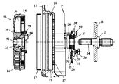
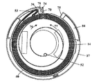
図1は、手で操縦される作業機の実施形態としてパワーソー1を示している。パワーソー1はケーシング2を有し、該ケーシングにはガイドレール8が固定装置12を介して固定されている。ガイドレール8には、スプロケットホイール10によって駆動されるチェーン9が周回するように案内されている。チェーン9はソーチェーンとして形成されている。作業機は石切断機であってもよく、石切断機の場合には、ガイドレール8に、石を切断するために切断チェーンとして形成されたチェーン9が配置される。チェーン9を張設するには、ガイドレール8をケーシング2に対して張設方向15に移動させる。張設方向15は、ケーシング2から、ガイドレール8の端部であって該ケーシング2から離間している前記端部のほうへ方向づけられている。ケーシング2が固定されている、ガイドレール8の領域も、スプロケットホイール10と同様にスプロケットホイールカバー11によって覆われている。   FIG. 1 shows a power saw 1 as an embodiment of a working machine operated by hand. The power saw 1 has a casing 2, and a guide rail 8 is fixed to the casing via a fixing device 12. The guide rail 8 is guided so that the chain 9 driven by the sprocket wheel 10 circulates. The chain 9 is formed as a saw chain. The working machine may be a stone cutting machine. In the case of a stone cutting machine, a chain 9 formed as a cutting chain for cutting stone is arranged on the guide rail 8. In order to stretch the chain 9, the guide rail 8 is moved in the stretching direction 15 with respect to the casing 2. The tensioning direction 15 is directed from the casing 2 toward the end of the guide rail 8 that is spaced from the casing 2. The area of the guide rail 8 to which the casing 2 is fixed is also covered with a sprocket wheel cover 11 like the sprocket wheel 10.

作動中にパワーソー1を操縦するため、ケーシング2に後部ハンドグリップ3が配置され、該後部ハンドグリップにはスロットルレバー4とスロットルレバーロック5とが回動可能に支持されている。スロットルレバー4を介して、ケーシング2内に配置されている駆動原動機150が操作される。本実施形態では、駆動原動機150は内燃エンジンとして構成されている。しかし駆動原動機150は電動機であってもよく、電動機は、接続ケーブルを介してエネルギー供給源と接続されているか、或いは、バッテリーまたはアキュムレータからエネルギーの供給を受ける。   In order to steer the power saw 1 during operation, a rear handgrip 3 is arranged on the casing 2, and a throttle lever 4 and a throttle lever lock 5 are rotatably supported on the rear handgrip. A drive prime mover 150 arranged in the casing 2 is operated via the throttle lever 4. In the present embodiment, the driving prime mover 150 is configured as an internal combustion engine. However, the drive motor 150 may be an electric motor, and the electric motor is connected to an energy supply source via a connection cable, or is supplied with energy from a battery or an accumulator.

パワーソー1は、該パワーソー1のケーシング2とオーバーラップしているグリップパイプ6と、該グリップパイプ6のガイドレール8側に延在している手保護部7とを有している。手保護部7は、有利には、チェーン9用のブレーキ装置(図示せず)を起動させるために用いる。   The power saw 1 includes a grip pipe 6 that overlaps the casing 2 of the power saw 1 and a hand protection portion 7 that extends to the guide rail 8 side of the grip pipe 6. The hand protector 7 is advantageously used to activate a brake device (not shown) for the chain 9.

固定装置12は操作装置19によって操作される。操作装置19は、本実施形態では、回転ホイールとして構成されている。図1に図示した、操作装置19の非操作状態では、操作装置19はスプロケットカバー11の外面とほぼ面一になっている。操作装置19を操作するには、該操作装置19の湾曲体26を外側へ開かねばならない。操作者が湾曲体26をうまく把持することができるようにするため、湾曲体26には把持凹部56が設けられている。固定装置12を解除するには、操作装置19を解除方向77へ回転させる。本実施形態では、解除方向77は回転方向において反時計方向に延びている。ガイドレール8を固定するため、操作装置19を固定方向76に回転させる。固定方向76は、本実施形態では時計方向に方向づけられている。操作装置19の回転運動の代わりに、操作装置19の他の運動も可能で、たとえばスプロケットホイールカバー11に沿った直線運動を設けるようにしてもよい。   The fixing device 12 is operated by the operation device 19. In the present embodiment, the operating device 19 is configured as a rotating wheel. In the non-operating state of the operating device 19 illustrated in FIG. 1, the operating device 19 is substantially flush with the outer surface of the sprocket cover 11. In order to operate the operating device 19, the curved body 26 of the operating device 19 must be opened outward. In order to allow the operator to grip the curved body 26 successfully, the curved body 26 is provided with a gripping recess 56. To release the fixing device 12, the operating device 19 is rotated in the release direction 77. In the present embodiment, the release direction 77 extends counterclockwise in the rotation direction. In order to fix the guide rail 8, the operating device 19 is rotated in the fixing direction 76. The fixing direction 76 is oriented clockwise in this embodiment. Instead of the rotational movement of the operating device 19, other movements of the operating device 19 are possible, for example a linear movement along the sprocket wheel cover 11 may be provided.

チェーン9を張設するため、パワーソー1は図4に図示した張設装置13を有している。張設装置13は図4に図示した引張りばね14を含んでいる。引張りばね14は、本実施形態では、コイルばねとして構成されている。引張りばね14は、後述する変位用スリットガイドに作用する。変位用スリットガイドも張設装置13の一部であり、引張りばね14の回転運動を、図1および図2に示した張設方向15でのガイドレール8の縦運動に変換する。   In order to stretch the chain 9, the power saw 1 has a tensioning device 13 shown in FIG. The tensioning device 13 includes a tension spring 14 illustrated in FIG. In this embodiment, the tension spring 14 is configured as a coil spring. The tension spring 14 acts on a displacement slit guide to be described later. The displacement slit guide is also a part of the tensioning device 13, and converts the rotational motion of the tension spring 14 into the vertical motion of the guide rail 8 in the tensioning direction 15 shown in FIGS.

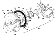
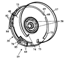
図2は張設装置13の一部分の展開図である。張設装置13の、操作装置19内に配置されている部分は、この図では見えない。スプロケットホイールカバー11は受容部20を有し、その底部89は開口部91を有している。開口部91は受容部20の端面の大部分にわたって延在し、その結果底部89は、実質的に、周回するように延在するエッジによって形成されている。底部89は歯付き輪郭部27を有している。その機能については後述する。受容部20の外周には摩擦面18が形成され、該摩擦面に対し摩擦ベルト17が作用する。摩擦ベルト17は、操作装置19と摩擦面18との間に位置するように操作装置19の外周に配置されている。摩擦ベルト17は摩擦面18とともに制止装置16を形成している。制止装置16の機能に関しては後述する。張設装置13は回転要素29と変位要素30とを含み、これら回転要素と変位要素とはスプロケットホイールカバー11のケーシング2側に配置されている。回転要素29には、後述するように、引張りばね14(図3および図4)の一端との相対回転不能結合に用いる駆動体(または連行体)28が相対回転不能に保持されている。回転要素29は変位用スリットガイドとしてスパイラルガイド21を有している。スパイラルガイド21内には、変位要素30のピン31が配置されている。変位要素30は図3に示した保持突起50でもってガイドレール8の開口部23内へ突出して、ガイドレール8と相対回転不能に結合されている。   FIG. 2 is a development view of a part of the tensioning device 13. The part of the tensioning device 13 arranged in the operating device 19 is not visible in this view. The sprocket wheel cover 11 has a receiving portion 20, and a bottom portion 89 has an opening 91. The opening 91 extends over most of the end face of the receptacle 20, so that the bottom 89 is formed by an edge that extends substantially around. The bottom 89 has a toothed contour 27. Its function will be described later. A friction surface 18 is formed on the outer periphery of the receiving portion 20, and the friction belt 17 acts on the friction surface. The friction belt 17 is disposed on the outer periphery of the operating device 19 so as to be positioned between the operating device 19 and the friction surface 18. The friction belt 17 forms a stop device 16 together with the friction surface 18. The function of the restraining device 16 will be described later. The tensioning device 13 includes a rotation element 29 and a displacement element 30, and these rotation element and displacement element are arranged on the casing 2 side of the sprocket wheel cover 11. As will be described later, the rotating element 29 holds a driving body (or an entraining body) 28 used for a relative non-rotatable coupling with one end of the tension spring 14 (FIGS. 3 and 4) so as not to be relatively rotatable. The rotating element 29 has a spiral guide 21 as a displacement slit guide. A pin 31 of the displacement element 30 is arranged in the spiral guide 21. The displacement element 30 protrudes into the opening 23 of the guide rail 8 by the holding projection 50 shown in FIG. 3 and is coupled to the guide rail 8 so as not to be relatively rotatable.

パワーソーのケーシング2には、固定ピン24とガイドピン25とが固定され、これらはそれぞれガイドレール8を当接させるための鍔32を有している。固定ピン24とガイドピン25とはガイドレール8の縦溝22を貫通している。固定ピン24とガイドピン25とは、さらに、図5に示した変位要素30の縦スリット41を貫通している。これにより、変位要素30とガイドレール8とを、縦溝22および縦スリット41の方向に方向づけられた張設方向15とケーシング2に対し逆方向とにおいて移動させることができる。回転軸線92のまわりでの回転要素29の回転により、ピン31とスパイラルガイド21内で移動する。これによって回転要素29の回転軸線92に対するピン31の間隔が変化する。回転軸線92は操作装置19の回転軸線である。ピン31と回転軸線92との間の間隔が小さくなると、変位要素30は張設方向15に変位する。   A fixing pin 24 and a guide pin 25 are fixed to the casing 2 of the power saw, and each has a flange 32 for contacting the guide rail 8. The fixing pin 24 and the guide pin 25 pass through the vertical groove 22 of the guide rail 8. The fixing pin 24 and the guide pin 25 further pass through the vertical slit 41 of the displacement element 30 shown in FIG. As a result, the displacement element 30 and the guide rail 8 can be moved in the tension direction 15 oriented in the direction of the longitudinal groove 22 and the longitudinal slit 41 and in the opposite direction with respect to the casing 2. The rotation of the rotating element 29 around the rotation axis 92 causes the pin 31 and the spiral guide 21 to move. As a result, the distance between the pin 31 and the rotation axis 92 of the rotating element 29 changes. The rotation axis 92 is the rotation axis of the operating device 19. When the distance between the pin 31 and the rotation axis 92 is reduced, the displacement element 30 is displaced in the tension direction 15.

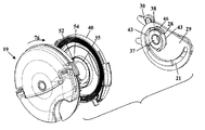
図3が示すように、駆動体28と回転要素29と変位要素30とは回転軸線92の方向で互い固定結合されている。この結合を確実にするため、リベットスリーブ37と皿ばね38とが用いられる。皿ばね38は、操作装置19を構造的に予め設定される角度範囲で引き締めたときに、常時増大する引き締めモーメントを生じさせる。これにより操作者は、螺合部が固定されてガイドレール8が締め付け保持されていることがわかる。前記構造的に予め設定される角度範囲は、ほぼ90゜ないしほぼ360゜であり、特にほぼ180゜である。この角度範囲は360゜以上であってもよい。   As shown in FIG. 3, the drive body 28, the rotation element 29, and the displacement element 30 are fixedly coupled to each other in the direction of the rotation axis 92. In order to ensure this connection, a rivet sleeve 37 and a disc spring 38 are used. The disc spring 38 generates a tightening moment that constantly increases when the operating device 19 is tightened within a structurally preset angle range. As a result, the operator knows that the screwing portion is fixed and the guide rail 8 is held tightly. The structurally preset angle range is approximately 90 ° to approximately 360 °, in particular approximately 180 °. This angular range may be 360 ° or more.

ガイドレール8を変位要素30に固定するため、保持突起50にねじ込まれる固定ねじ36を設けてよい。これにより、操作装置19が完全に固定されていない場合、保持突起50が開口部23から抜け出てガイドレール8にだけ当接するのが阻止される。また図3が示すように、スパイラルガイド21には隆起部49が形成されている。回転要素29は有利には厚い鋼板から成り、この鋼板にスパイラルガイド21が刻設される。スパイラルガイド21を刻設する際に隆起部49が生じる。鋼材はたとえば1mm以上の厚さを有していてよい。これにより、回転要素29に大きな力が作用しても、回転要素29の機械的安定性が確保される。   In order to fix the guide rail 8 to the displacement element 30, a fixing screw 36 to be screwed into the holding projection 50 may be provided. Thereby, when the operating device 19 is not completely fixed, the holding projection 50 is prevented from coming out of the opening 23 and contacting only the guide rail 8. As shown in FIG. 3, the spiral guide 21 has a raised portion 49. The rotary element 29 is preferably made of a thick steel plate, on which the spiral guide 21 is engraved. When the spiral guide 21 is engraved, a raised portion 49 is generated. The steel material may have a thickness of 1 mm or more, for example. Thereby, even if a large force acts on the rotating element 29, the mechanical stability of the rotating element 29 is ensured.

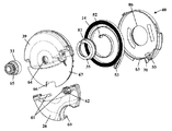
図3が示すように、張設装置13の引張りばね14は操作装置19の内部空間34内に配置されている。操作装置19は、内部空間34を画成しているベース体39を有している。ベース体39にはスクリュースリーブ33が保持されている。スクリュースリーブ33は、ベース体39と形状拘束的に結合され、および/または、有利にはプラスチック部材であるベース体39に射出成形されている。スクリュースリーブ33は、図4が示すように、固定装置12を固定ボルト24に螺着するために用いられる。   As shown in FIG. 3, the tension spring 14 of the tensioning device 13 is disposed in the internal space 34 of the operating device 19. The operating device 19 has a base body 39 that defines an internal space 34. A screw sleeve 33 is held on the base body 39. The screw sleeve 33 is connected in a shape-constrained manner with the base body 39 and / or is injection-molded into the base body 39 which is preferably a plastic member. As shown in FIG. 4, the screw sleeve 33 is used for screwing the fixing device 12 to the fixing bolt 24.

図3と図4が示すように、引張りばね14はばねケース40内に配置され、ばねケース40は操作装置19の内部空間34をスプロケットホイールカバー11の内面に対し閉鎖させている。これによって引張りばね14は汚染から保護されている。ベース体39には駆動体35が回転可能に支持されている。駆動体35には引張りばね14の内端が固定され、外端はベース体39と相対回転不能に結合されている。駆動体35は少なくとも1つの駆動体突出部58を有している。本実施形態では、互いに対向しあっている2つの駆動体突出部58が設けられ、そのうち図3には1つが図示されている。各駆動体突出部58は、駆動体28の、図5に図示した駆動体突出部43の間に突出して、引張りばね14の内端と駆動体28との間の相対回転不能結合を形成させている。駆動体48は、図5に図示した凹部44と回転要素29に設けたピン45とを介して、回転要素29と相対回転不能に結合されている。これにより引張りばね14のばね力は回転要素29に作用する。   As shown in FIGS. 3 and 4, the tension spring 14 is disposed in the spring case 40, and the spring case 40 closes the inner space 34 of the operating device 19 with respect to the inner surface of the sprocket wheel cover 11. As a result, the tension spring 14 is protected from contamination. A drive body 35 is rotatably supported on the base body 39. The inner end of the tension spring 14 is fixed to the drive body 35, and the outer end is coupled to the base body 39 so as not to be relatively rotatable. The driving body 35 has at least one driving body protrusion 58. In the present embodiment, two driving body protrusions 58 that face each other are provided, of which one is shown in FIG. Each driving body protrusion 58 protrudes between the driving body protrusions 43 shown in FIG. 5 of the driving body 28 to form a relatively non-rotatable coupling between the inner end of the tension spring 14 and the driving body 28. ing. The driving body 48 is coupled to the rotating element 29 so as not to rotate relative to each other via the recess 44 illustrated in FIG. 5 and a pin 45 provided on the rotating element 29. As a result, the spring force of the tension spring 14 acts on the rotating element 29.

図4が示すように、固定装置12を固定すると、スクリュースリーブ33は皿ばね38と、駆動体28と、回転要素29と、変位要素30とを介してガイドレール8に対し作用を及ぼし、これによってガイドレール8を鍔32と、図4に図示したパワーサー1のケーシング2とに押圧させる。有利には、スクリュースリーブ33と皿ばね38と駆動体28と回転要素29と変位要素30とは金属から成っており、その結果ガイドレール8の好適な固定が生じる。   As shown in FIG. 4, when the fixing device 12 is fixed, the screw sleeve 33 acts on the guide rail 8 via the disc spring 38, the driving body 28, the rotating element 29, and the displacement element 30. Thus, the guide rail 8 is pressed against the flange 32 and the casing 2 of the power surler 1 shown in FIG. Advantageously, the screw sleeve 33, the disc spring 38, the drive body 28, the rotary element 29 and the displacement element 30 are made of metal, so that a suitable fixing of the guide rail 8 takes place.

内19のベース体39はその端面にエッジ83を有し、エッジ83は受容部20の底部89に対し押圧されて、スプロケットホイールカバー11をケーシング2に対し押圧し、その結果スプロケットホイールカバー11が好適に固定される。有利には、ベース体39は、すプロけってホイールカバー11を固定するための締め付け力が直接スプロケットホイールカバー11の受容部20の底部89に導入され、ばねケース40のような他の構成要素を力伝達系の中に配置しなくても済むように、構成されている。これは、公差を適宜設計することにより、或いは、所定の当接面積に応じた構成を採用することによって達成できる。   The base body 39 of the inner 19 has an edge 83 on its end face, and the edge 83 is pressed against the bottom 89 of the receiving portion 20 to press the sprocket wheel cover 11 against the casing 2, so that the sprocket wheel cover 11 is It is preferably fixed. Advantageously, the base body 39 is provided with a clamping force for fixing the wheel cover 11 directly on the bottom 89 of the receiving part 20 of the sprocket wheel cover 11 and other components such as the spring case 40. Is not required to be arranged in the force transmission system. This can be achieved by appropriately designing tolerances or by adopting a configuration corresponding to a predetermined contact area.

図5ないし図7は張設装置13の詳細図である。張設装置13はリベットスリーブ37を含み、該リベットスリーブは、変位要素30の縦スリット41と、回転要素29の開口部51と、駆動体28の開口部42と、皿ばね38とを貫通突出している。リベットスリーブ37はこれらの構成要素を軸線方向に位置固定するように、しかし回転可能に結合させている。駆動体28と回転要素39との相対回転不能な結合は、駆動体28に設けた凹部44と、回転要素29に設けたピン45とによって達成される。回転要素29は2つの駆動体開口部46を有し、これらの駆動体開口部46は、駆動体35の駆動体突出部58(図3)が駆動体開口部46に係合できるように、方向づけられている。これにより、さらに、駆動体35と回転要素29との間のダイレクトな相対回転不能結合を達成できる。駆動体28の駆動体突出部43および回転要素29の駆動体開口部46のサイズおよび公差に関する設計に応じて、駆動体突出部43、駆動体開口部46、またはその双方を介して前記相対回転不能な結合が達成される。   5 to 7 are detailed views of the tensioning device 13. The tensioning device 13 includes a rivet sleeve 37, which projects through the longitudinal slit 41 of the displacement element 30, the opening 51 of the rotating element 29, the opening 42 of the driving body 28, and the disc spring 38. ing. The rivet sleeve 37 couples these components axially, but rotatably. The relatively non-rotatable coupling between the driving body 28 and the rotating element 39 is achieved by a recess 44 provided in the driving body 28 and a pin 45 provided on the rotating element 29. The rotating element 29 has two drive body openings 46, which allow the drive body protrusions 58 (FIG. 3) of the drive body 35 to engage the drive body openings 46. Oriented. Thereby, a direct relative non-rotatable coupling between the driving body 35 and the rotating element 29 can be further achieved. Depending on the design of the drive body protrusion 43 of the drive body 28 and the drive body opening 46 of the rotating element 29 and the design related to tolerances, the relative rotation is achieved via the drive body protrusion 43, the drive body opening 46, or both. Impossible coupling is achieved.

図6は、リベットスリーブ37と皿ばね38を備えた回転要素29を、構成を明確にするために皿ばね38と回転要素29との間に配置される駆動体28を省略して示したものである。駆動体28が皿ばね38と回転要素29との間に配置されている実際の配置構成は、図7に図示されている。   FIG. 6 shows the rotating element 29 provided with the rivet sleeve 37 and the disc spring 38 with the driving body 28 disposed between the disc spring 38 and the rotating element 29 omitted for the sake of clarity. It is. The actual arrangement in which the drive body 28 is arranged between the disc spring 38 and the rotating element 29 is illustrated in FIG.

図5がさらに示すように、ピン31に隣接するように変位要素30には位置固定輪郭部48が形成されている。位置固定輪郭部48は、ピン31の、縦スリット41とは逆の側に配置されている。回転要素29は位置固定輪郭部47を有し、該位置固定輪郭部47に位置固定輪郭部48が固定装置12を完全に固定した時に係合する。これによって回転要素29と変位要素30との形状拘束的結合が達成される。位置固定輪郭部47と48は、作動中に回転要素29が変位要素30に対し回転するのを阻止し、よってチェーン9の張設が変化しないように、特にチェーン9が緩まないようにする位置固定装置59(図6)を形成している。   As further shown in FIG. 5, a fixed position contour 48 is formed in the displacement element 30 so as to be adjacent to the pin 31. The position fixing contour 48 is disposed on the side of the pin 31 opposite to the vertical slit 41. The rotating element 29 has a position fixing contour 47 which engages when the position fixing contour 48 completely fixes the fixing device 12. As a result, a shape-constrained connection between the rotating element 29 and the displacement element 30 is achieved. Position locking contours 47 and 48 prevent the rotation element 29 from rotating relative to the displacement element 30 during operation, so that the tensioning of the chain 9 is not changed, in particular the chain 9 is not loosened. A fixing device 59 (FIG. 6) is formed.

図5が示すように、スパイラルガイド21は回転軸線92のまわりでの1回転以下に相当する分だけ延在している。これにより、スパイラルガイド21が周方向と成す角度は比較的大きい。これにより、チェーン張力が引張りばね14の力を著しく越えたときに、ガイドレール8は変位要素30を引張りばね14の力に抗して張設方向15とは逆方向へ移動させることができる。このケースは、たとえばチェーン9を暖かい状態で張設し、その後張設装置13を固定するようなケースである。冷えている状態ではチェーン9が収縮し、これによってチェーン張力は著しく大きくなる。この時、チェーン9を場合によっては手でもガイドレール8を介して移動させることはできない。   As shown in FIG. 5, the spiral guide 21 extends by an amount corresponding to one rotation or less around the rotation axis 92. Thereby, the angle which the spiral guide 21 makes with the circumferential direction is comparatively large. Thus, when the chain tension significantly exceeds the force of the tension spring 14, the guide rail 8 can move the displacement element 30 in the direction opposite to the tension direction 15 against the force of the tension spring 14. In this case, for example, the chain 9 is stretched in a warm state, and then the stretching device 13 is fixed. In the cold state, the chain 9 contracts, which causes the chain tension to increase significantly. At this time, the chain 9 cannot be moved via the guide rail 8 by hand depending on the case.

図6と図7が示しているように、引張りばね14はコイルばねとして形成されている。引張りばね14は外端53を有し、この外端はばねケース40の受容部55に固定されている。引張りばね14は内端52を有し、この内端は駆動体35に設けた受容部54に掛止されている。操作装置19はばねケース40と相対回転不能に結合されている。固定方向76での操作装置19の回転により、引張りばね14の外端53は内端52に対し移動する。これによって引張りばね14が緊張する。   As shown in FIGS. 6 and 7, the tension spring 14 is formed as a coil spring. The tension spring 14 has an outer end 53, which is fixed to the receiving portion 55 of the spring case 40. The tension spring 14 has an inner end 52, and this inner end is hooked on a receiving portion 54 provided in the drive body 35. The operating device 19 is coupled to the spring case 40 so as not to be relatively rotatable. The outer end 53 of the tension spring 14 moves relative to the inner end 52 by the rotation of the operating device 19 in the fixing direction 76. This tensions the tension spring 14.

図6に示唆したように、湾曲体26は回動軸線57のまわりで操作装置19のベース体39に対し回動可能である。このため、図8に図示した2つの支持ピン61が設けられている。支持ピン61は湾曲体26を回動可能にベース体39で支持している。湾曲体26は、ばね62を介して、受容部20に連結される位置の方向に張設されている。湾曲体26は、該湾曲体26の連結時に回転軸線92(図4)に対しほぼ平行に延在する少なくとも1つの固定ピン60を有している。湾曲体26は連結状態でベース体39の壁67に隣接している。図4が示すように、壁67は内部空間34をも画成しており、その結果引張りばね14は汚染から保護されている。壁67は繰り抜き部66を有し、該繰り抜き部を固定ピン60が貫通突出している。固定ピン60は、受容部20の底部89に設けた、図2および図3に図示した歯付き輪郭部27に係合して、操作装置19を形状拘束的に固定することでスプロケットホイールカバー11での回転を阻止している。図2が示すように、歯付き輪郭部27はスプロケットホイールカバー11の内部空間のほうへ開口している。これにより、歯付きリング27の領域に集積した塵埃が固定ピン60からスプロケットホイールカバー11の内部へ押され、そこから周囲に到達する。これによって歯付きリング27の消耗が阻止されている。   As suggested in FIG. 6, the bending body 26 can rotate with respect to the base body 39 of the operating device 19 around the rotation axis 57. For this reason, the two support pins 61 shown in FIG. 8 are provided. The support pin 61 supports the curved body 26 with a base body 39 so as to be rotatable. The bending body 26 is stretched in the direction of the position where it is connected to the receiving portion 20 via the spring 62. The bending body 26 has at least one fixing pin 60 that extends substantially parallel to the rotation axis 92 (FIG. 4) when the bending body 26 is connected. The curved body 26 is adjacent to the wall 67 of the base body 39 in a connected state. As FIG. 4 shows, the wall 67 also defines the interior space 34 so that the tension spring 14 is protected from contamination. The wall 67 has a pull-out portion 66, and the fixing pin 60 projects through the pull-out portion. The fixing pin 60 is engaged with the toothed contour portion 27 shown in FIGS. 2 and 3 provided on the bottom portion 89 of the receiving portion 20 to fix the operating device 19 in a shape-constrained manner, whereby the sprocket wheel cover 11 is fixed. The rotation at is prevented. As shown in FIG. 2, the toothed contour 27 opens toward the inner space of the sprocket wheel cover 11. As a result, the dust accumulated in the region of the toothed ring 27 is pushed into the sprocket wheel cover 11 from the fixing pin 60 and reaches the periphery from there. This prevents the toothed ring 27 from being consumed.

図8が示すように、ベース体39は歯部64を有し、この歯部にスクリュースリーブ33の歯部65が係合している。これによってスクリュースリーブ33はベース体で形状拘束的に保持されている。歯部64と65を互いに別個に製造して、スクリュースリーブ33をベース体39内へ圧入するようにしてもよい。しかし、歯部65を備えたスクリュースリーブ33をベース体39から押し出し被覆し、その際に歯部64が生じるようにしてもよい。   As shown in FIG. 8, the base body 39 has a tooth portion 64, and the tooth portion 65 of the screw sleeve 33 is engaged with the tooth portion. As a result, the screw sleeve 33 is held in a shape-constrained manner by the base body. The tooth portions 64 and 65 may be manufactured separately, and the screw sleeve 33 may be press-fitted into the base body 39. However, the screw sleeve 33 provided with the tooth portion 65 may be extruded and covered from the base body 39, and the tooth portion 64 may be generated at that time.

図8と図12が示すように、ばねケース40は開口部86を有し、該開口部86を駆動体35が貫通突出している。駆動体35は外側へ突出して周回するように延在しているエッジ87を有し、該エッジ87は開口部86に隣接してばねケース40に当接し、駆動体35を軸線方向に位置固定させる。ばねケース40は、開口部86に隣接するように、駆動体35のエッジ87の領域を取り囲む接続部材88を有している。駆動体突出部58は接続部材88から突出している。駆動体突出部58は傾斜部71を有し、該傾斜部71は、駆動体35を駆動体28に嵌合させるときに案内傾斜部として用いられ、嵌合を容易にさせる。操作装置19を解除方向77(図11)に操作すると、傾斜部71が設けられているため、操作装置19が固定ボルト24(図4)から十分に離間して取り外されたときに、駆動体突出部58と駆動体28の駆動体突出部43(図7)との係合が解除される。これにより、引張りばね14が逆回転することにより、すなわち引張りばね14が引張り方向とは逆方向に回転することにより破損するのが回避される。ばねケース40での駆動体35の配置は図9にも図示されている。   As shown in FIGS. 8 and 12, the spring case 40 has an opening 86, and the driving body 35 projects through the opening 86. The drive body 35 has an edge 87 extending so as to project outward and circulate. The edge 87 abuts against the spring case 40 adjacent to the opening 86 and fixes the drive body 35 in the axial direction. Let The spring case 40 has a connection member 88 that surrounds the region of the edge 87 of the drive body 35 so as to be adjacent to the opening 86. The driving body protrusion 58 protrudes from the connection member 88. The driving body protruding portion 58 has an inclined portion 71, and the inclined portion 71 is used as a guide inclined portion when the driving body 35 is fitted to the driving body 28, thereby facilitating the fitting. When the operating device 19 is operated in the release direction 77 (FIG. 11), the inclined portion 71 is provided. Therefore, when the operating device 19 is removed sufficiently away from the fixing bolt 24 (FIG. 4), the driver The engagement between the protrusion 58 and the driving body protrusion 43 (FIG. 7) of the driving body 28 is released. Thereby, it is avoided that the tension spring 14 is reversely rotated, that is, the tension spring 14 is damaged by rotating in the direction opposite to the tension direction. The arrangement of the driving body 35 in the spring case 40 is also shown in FIG.

図9が示すように、ベース体39のエッジ83は繰り抜き部69を有し、該繰り抜き部69内に、ばねケース40のエッジ81に形成された突起68が突出している。これによってばねケース40とベース体39とは互いに相対回転不能に結合されている。図9がさらに示すように、べース体39は支持細条部82を有し、該支持細条部82は、たとえば薄い射出成形部品としてプラスチックから形成されていてよいばねケース40を支持し、ばねケース40の変形を阻止する。   As shown in FIG. 9, the edge 83 of the base body 39 has a withdrawal portion 69, and a protrusion 68 formed on the edge 81 of the spring case 40 projects into the withdrawal portion 69. Accordingly, the spring case 40 and the base body 39 are coupled to each other so as not to rotate relative to each other. As further shown in FIG. 9, the base body 39 has a support strip 82 which supports a spring case 40 which may be made of plastic, for example as a thin injection molded part. The deformation of the spring case 40 is prevented.

図8が示すように、ばねケース40は操作細条部70を有している。図10はばねケース40に設けた摩擦ベルト17を示している。摩擦ベルト17は第1の端部74と、第2の端部75とを有している。第1の端部74は、操作細条部70とばねケース40に形成された第1の係止面78との間に突出している。第1の係止面78は図11に図示され、図10では概略的に図示してある。第2の端部75は、ベース体39の壁80と湾曲体26に設けた壁93との間に突出している。これは図11に図示してある。   As shown in FIG. 8, the spring case 40 has an operation strip portion 70. FIG. 10 shows the friction belt 17 provided in the spring case 40. The friction belt 17 has a first end portion 74 and a second end portion 75. The first end portion 74 protrudes between the operating strip portion 70 and a first locking surface 78 formed on the spring case 40. The first locking surface 78 is illustrated in FIG. 11 and schematically illustrated in FIG. The second end 75 projects between the wall 80 of the base body 39 and the wall 93 provided on the curved body 26. This is illustrated in FIG.

操作装置21が完全に開口している状態では、引張りばね14は弛緩している。操作装置19を固定方向76に回転させると、すなわち図10の図示で時計方向に回転させると、操作装置19のベース体39とばねケース40と歯摩擦ベルト17に対して移動して、第1の係止面78が摩擦ベルト17の第1の端部74と接触する。このとき第2の端部75は壁93に対し間隔を有している。係止面78は摩擦ベルト17を連行し、これによって摩擦ベルト17の径をわずかに縮小させる。これによって摩擦ベルト17と摩擦面18との間にわずかな摩擦抵抗が発生し、操作装置19を簡単に操作することができる。   When the operating device 21 is fully open, the tension spring 14 is relaxed. When the operating device 19 is rotated in the fixing direction 76, that is, when the operating device 19 is rotated in the clockwise direction in FIG. 10, the first body moves relative to the base body 39, the spring case 40, and the tooth friction belt 17 of the operating device 19. The locking surface 78 contacts the first end 74 of the friction belt 17. At this time, the second end portion 75 is spaced from the wall 93. The locking surface 78 entrains the friction belt 17 and thereby reduces the diameter of the friction belt 17 slightly. As a result, a slight frictional resistance is generated between the friction belt 17 and the friction surface 18, and the operating device 19 can be easily operated.

引張りばね14の内端52は回転要素29と相対回転不能に結合されている。ガイドレール8と固定ピン24とガイドピン25とケーシング2(図4)との間の摩擦抵抗により、引張りばね14の弛緩時に内端52は位置固定して保持されている。これにより、引張りばね14は固定方向76での操作装置19の操作時に緊張する。引張りばね14の力が、回転要素29と変位要素30とガイドレール8とに作用する摩擦力を上回ると、回転要素29が回転し、変位要素30がガイドレール8とともに変位し、その際にチェーン9を緊張させる。引張りばね14の最大引張り力は張設装置13を完全に固定するかなり以前に達成され、その結果所望の緊張力でのチェーン9の張設が保証されている。その際スクリュースリーブ33と固定ピン24とは、固定装置12を完全に固定した時に引張りばね14がまだ完全に緊張状態でないように、引張りばね14に対し整合されている。引張りばね14の最大引張り距離は、すなわち引張りばね14を最大に緊張させることのできる回転の回数は、固定装置12の最大操作距離よりも大きく、すなわちガイドレール8が変位要素30と固定ピン24との間で締め付け固定されるまで操作装置19を固定ボルト24に螺合させることのできるねじ山の数量よりも大きい。操作装置19を固定方向76に回転させると、スクリュースリーブ33が固定ピン24に螺合し、これによってガイドレール8が固定される。同時に引張りばね14が緊張状態になる。引張りばね14は緊張方向15でのガイドレール8の変位によってチェーン9を緊張させる。チェーン9の緊張は、チェーン9がガイドレール8上に完全に当接するまで行う。操作装置19の最後の回転の際に、位置固定輪郭部47と48が互いに形状拘束的に係合し、その結果回転要素19と変位要素30とはもはや互いに相対的に回転することができない。操作装置19をさらに固定方向76に回転させると、ガイドレール8が締め付けられて固定される。   The inner end 52 of the tension spring 14 is coupled to the rotating element 29 so as not to rotate relative thereto. Due to the frictional resistance between the guide rail 8, the fixing pin 24, the guide pin 25, and the casing 2 (FIG. 4), the inner end 52 is held in a fixed position when the tension spring 14 is relaxed. Accordingly, the tension spring 14 is tensioned when the operating device 19 is operated in the fixing direction 76. When the force of the tension spring 14 exceeds the frictional force acting on the rotation element 29, the displacement element 30 and the guide rail 8, the rotation element 29 rotates and the displacement element 30 is displaced together with the guide rail 8, and in that case the chain Tension 9 The maximum tension force of the tension spring 14 is achieved long before the tensioning device 13 is completely fixed, so that the tensioning of the chain 9 with the desired tension is ensured. In this case, the screw sleeve 33 and the fixing pin 24 are aligned with respect to the tension spring 14 so that the tension spring 14 is not yet fully tensioned when the fixing device 12 is completely fixed. The maximum tension distance of the tension spring 14, that is, the number of rotations at which the tension spring 14 can be tensioned to the maximum, is greater than the maximum operating distance of the fixing device 12, that is, the guide rail 8 is connected to the displacement element 30 and the fixing pin 24. It is larger than the quantity of the thread which can screw the operating device 19 in the fixing bolt 24 until it clamps and fixes between. When the operating device 19 is rotated in the fixing direction 76, the screw sleeve 33 is screwed into the fixing pin 24, whereby the guide rail 8 is fixed. At the same time, the tension spring 14 is in tension. The tension spring 14 tensions the chain 9 by the displacement of the guide rail 8 in the tension direction 15. The chain 9 is tensioned until the chain 9 completely contacts the guide rail 8. During the final rotation of the operating device 19, the position fixing contours 47 and 48 engage with each other in a shape-constrained manner, so that the rotating element 19 and the displacement element 30 can no longer rotate relative to each other. When the operating device 19 is further rotated in the fixing direction 76, the guide rail 8 is tightened and fixed.

変位要素30は図5に示した線63に沿って回転要素29からわずかに離間しており、ガイドレール8のほうへ湾曲している。固定装置12が解除された状態では、位置固定輪郭部47と48は互いに係合していない。システムを引き締めたときに変位要素30がガイドレール8に当接し、変位要素30の、ピン31を有している領域が、回転要素29のほうへ湾曲した時にはじめて、位置固定輪郭部47と48が互いに係合し合う。   The displacement element 30 is slightly spaced from the rotation element 29 along the line 63 shown in FIG. 5 and is curved towards the guide rail 8. In a state where the fixing device 12 is released, the position fixing contour portions 47 and 48 are not engaged with each other. Only when the displacement element 30 abuts against the guide rail 8 when the system is tightened and the region of the displacement element 30 with the pin 31 is bent towards the rotation element 29, the position fixing contours 47 and 48 are not provided. Engage each other.

固定装置12を解除すると、すなわち操作装置19を解除方向77に回転させると、操作細条部70が摩擦ベルト17の第1の端部74に当接する。その際摩擦ベルト17の第2の端部75は壁80と接触しない。操作細条部70が解除方向77に移動するため、摩擦ベルト17がわずかに拡張し、摩擦面18に対し押圧される。これにより、操作者は、操作装置を解除方向に操作するには、さらに摩擦ベルト17と摩擦面18との間の摩擦抵抗を克服しなければならない。引張りばね14も同様に解除方向77においてばねケース40と操作装置19とに作用する。もし操作者が操作装置19を任意の非完全固定位置で手を離すと、引張りばね14は操作細条部70を摩擦ベルト17の第1の端部74のほうへ移動させ、これによって操作装置19の摩擦固定を生じさせる。これにより、操作装置19の自動戻り回転が引張りばね14の力によって阻止されている。固定装置12を固定していないときの引張りばね14の弛緩は、制止装置16によって阻止されている。引張りばね14のわずかな弛緩は、摩擦ベルト17が摩擦面18に摩擦当接するまで可能である。コイルばねとして形成された引張りばね14の、広範囲にわたって一定のばね力を生じさせるばね定数により、張設装置13の機能にとって引張りばね14のわずかな弛緩は問題でない。操作装置19を固定ボルト24から完全に取り外すと、引張りばね14は完全に弛緩する。   When the fixing device 12 is released, that is, when the operation device 19 is rotated in the release direction 77, the operation strip portion 70 contacts the first end portion 74 of the friction belt 17. At this time, the second end 75 of the friction belt 17 does not contact the wall 80. Since the operating strip portion 70 moves in the release direction 77, the friction belt 17 is slightly expanded and pressed against the friction surface 18. As a result, the operator must overcome the frictional resistance between the friction belt 17 and the friction surface 18 in order to operate the operating device in the release direction. Similarly, the tension spring 14 acts on the spring case 40 and the operating device 19 in the release direction 77. If the operator releases the operating device 19 in any incompletely fixed position, the tension spring 14 moves the operating strip 70 toward the first end 74 of the friction belt 17, thereby causing the operating device. 19 frictional locks are produced. Thereby, the automatic return rotation of the operating device 19 is prevented by the force of the tension spring 14. The relaxation of the tension spring 14 when the fixing device 12 is not fixed is prevented by the restraining device 16. Slight relaxation of the tension spring 14 is possible until the friction belt 17 is in frictional contact with the friction surface 18. Due to the spring constant of the tension spring 14 formed as a coil spring that produces a constant spring force over a wide range, slight relaxation of the tension spring 14 is not a problem for the function of the tensioning device 13. When the operating device 19 is completely removed from the fixing bolt 24, the tension spring 14 is completely relaxed.

図11が示すように、ベース体19は、操作細条部70に隣接して支持リブ85を有し、該支持リブで操作細条部70が支持されている。これにより、摩擦ベルト17の第1の端部74による操作細条部70の過度な変形が阻止される。   As shown in FIG. 11, the base body 19 has a support rib 85 adjacent to the operation strip portion 70, and the operation strip portion 70 is supported by the support rib. Thereby, the excessive deformation | transformation of the operation strip part 70 by the 1st edge part 74 of the friction belt 17 is prevented.

図11が示すように、引張りばね14の中心軸線72は操作装置19の回転軸線92に対しわずかな間隔で配置されている。これにより、固定ピン60に対し十分な構成空間が提供される。同時に、引張りばね14が回転軸線92に対し軸線をずらして配置されていることにより、引張りばね14の大きな外周が得られる。その際、中心軸線72は引張りばね14の外側壁の幾何学的中心である。図11は内端52に駆動体35が掛止されていることをも示している。また図11が示すように、ばねケース40の領域84は支持リブ85に当接している。   As shown in FIG. 11, the central axis 72 of the tension spring 14 is arranged at a slight interval with respect to the rotation axis 92 of the operating device 19. Thereby, a sufficient configuration space is provided for the fixing pin 60. At the same time, since the tension spring 14 is arranged with its axis shifted from the rotation axis 92, a large outer periphery of the tension spring 14 is obtained. The central axis 72 is then the geometric center of the outer wall of the tension spring 14. FIG. 11 also shows that the driving body 35 is hooked on the inner end 52. As shown in FIG. 11, the region 84 of the spring case 40 is in contact with the support rib 85.

図12ないし図15が示すように、本実施形態では、2つの固定ピン60が設けられている。他の個数の固定ピン60も有利であり、たとえば1個または3個またはそれ以上の固定ピン60も有利である。湾曲体26を内側へ回転させたときに1つの固定ピン60が隙間にぶつからずに、歯輪郭部27の細条部にぶつかると、歯輪郭部27が破損することがある。歯輪郭部27に作用する力を軽減し、歯輪郭部27の破損を回避するため、複数の固定ピン60を設けるのが有利である。有利には、少なくとも1つの固定ピン60は金属から成り、或いは、金属被覆部を有しているのがよい。これにより固定ピン60の摩耗を低減させることができる。図13はばねケース40の領域84を支持細条部82に配置した構成を示している。また図13が示すように、ベース体39はばねケース40に形状拘束的に係合している。このため、繰り抜き部69の両側に位置するようにベース体39に複数の細条部73が形成され、これらの細条部73はエッジ83の一部であり、受容部20の底部89(図2)に対し作用する。細条部73は歯輪郭部27を部分的に覆っている。これにより、塵埃がスプロケットホイールカバー11の内部空間から歯輪郭部27を通って摩擦ベルト17に到達するのが困難になる。   As shown in FIGS. 12 to 15, in this embodiment, two fixing pins 60 are provided. Other numbers of fixing pins 60 are also advantageous, for example one or three or more fixing pins 60 are also advantageous. When the curved body 26 is rotated inward, the tooth contour 27 may be damaged if the fixed pin 60 does not collide with the gap but hits the strip of the tooth contour 27. In order to reduce the force acting on the tooth contour 27 and to avoid damage to the tooth contour 27, it is advantageous to provide a plurality of fixing pins 60. Advantageously, the at least one fixing pin 60 is made of metal or may have a metal coating. Thereby, the wear of the fixing pin 60 can be reduced. FIG. 13 shows a configuration in which the region 84 of the spring case 40 is disposed on the support strip 82. Further, as shown in FIG. 13, the base body 39 is engaged with the spring case 40 in a shape-constrained manner. For this reason, a plurality of strips 73 are formed on the base body 39 so as to be positioned on both sides of the punched-out portion 69, and these strips 73 are part of the edge 83, and the bottom 89 ( Acts on FIG. The strip portion 73 partially covers the tooth contour portion 27. This makes it difficult for dust to reach the friction belt 17 from the internal space of the sprocket wheel cover 11 through the tooth contour portion 27.

図13と図14は、互いに対向し合うように配置された、駆動体35の2つの駆動体突出部58をも示している。   FIGS. 13 and 14 also show two drive body protrusions 58 of the drive body 35 arranged so as to face each other.

図15の拡大図が示しているように、第1の端部74は係止面78と操作細条部70との間にある。係止面78と操作細条部70との間隔は、第2の端部75と壁80または壁93との間隔よりも著しく小さい。これにより、第2の端部75が壁80または壁93と接触しないよう保証されている。本実施形態では、壁93は1個の固定ピン60に形成されている。第2の端部75は作動中に機能しない。摩擦ベルト17を対称形成することにより、摩擦ベルト17の取り付けミスは起こり得ない。   As shown in the enlarged view of FIG. 15, the first end 74 is located between the locking surface 78 and the operating strip 70. The distance between the locking surface 78 and the operating strip 70 is significantly smaller than the distance between the second end 75 and the wall 80 or wall 93. This ensures that the second end 75 does not contact the wall 80 or the wall 93. In the present embodiment, the wall 93 is formed on one fixing pin 60. The second end 75 does not function during operation. By forming the friction belt 17 symmetrically, an attachment error of the friction belt 17 cannot occur.

図16ないし図19は、操作装置19および張設装置13の他の1実施形態を示している。なお、前記の図に図示した対応する構成要素には同一の参照符号を付すので、前記の図の説明を参照してもらいたい。   16 to 19 show another embodiment of the operating device 19 and the tensioning device 13. In addition, since the same reference numerals are given to the corresponding components shown in the above figures, please refer to the explanation of the above figures.

図16の操作装置19は湾曲体26を有し、該湾曲体は外側へ突出する固定ピン90を有している。図17が示すように、受容部20には、スプロケットホイールカバー11の内部空間に対し閉じるように形成された歯輪郭部97が形成されている。   The operation device 19 shown in FIG. 16 has a curved body 26, and the curved body has a fixing pin 90 protruding outward. As shown in FIG. 17, the receiving portion 20 is formed with a tooth contour portion 97 formed so as to be closed with respect to the internal space of the sprocket wheel cover 11.

図16が示すように、張設装置13は、引張りばね95と外引張りばね95に一体成形された摩擦ベルト96とを含んでいる弾性要素94を有している。摩擦ベルト96は、引張りばね95の巻回方向とは逆の方向で該引張りばね95を取り囲んでいる。摩擦ベルト96の第1の端部74には、引張りばね95の外端103が接続している。引張りばね95の内端102は駆動体105への掛止のために形成されている。このため、駆動体105は受容部54を有している。駆動体105はリング状に形成され、その内周に全部で4つの駆動体突出部106を有している。各駆動体突出部106は傾斜部107を有し、該傾斜部は駆動体突出部106の端面全体にわたって延在している。張設装置13は回転要素99を含み、該回転要素に駆動体108が一体成形されている。駆動体108は別個の部材から形成されていてもよく、回転要素99に相対回転不能に固定されていてよい。駆動体108はその外周に全部で4つの駆動体突出部109を有し、これらの駆動体突出部はその駆動体105側端面に傾斜部110を有している。傾斜部107と110は案内傾斜部を形成しており、駆動体105と108相互の差し込みを容易にする。   As shown in FIG. 16, the tensioning device 13 has an elastic element 94 including a tension spring 95 and a friction belt 96 integrally formed with the outer tension spring 95. The friction belt 96 surrounds the tension spring 95 in a direction opposite to the winding direction of the tension spring 95. The outer end 103 of the tension spring 95 is connected to the first end 74 of the friction belt 96. The inner end 102 of the tension spring 95 is formed for latching on the driving body 105. For this reason, the driving body 105 has a receiving portion 54. The driving body 105 is formed in a ring shape and has four driving body protrusions 106 on the inner periphery thereof. Each driving body protrusion 106 has an inclined portion 107, and the inclined portion extends over the entire end surface of the driving body protrusion 106. The tensioning device 13 includes a rotating element 99, and a driving body 108 is integrally formed on the rotating element. The driving body 108 may be formed of a separate member, and may be fixed to the rotating element 99 so as not to be relatively rotatable. The drive body 108 has a total of four drive body protrusions 109 on the outer periphery thereof, and these drive body protrusions have an inclined portion 110 on the end face of the drive body 105. The inclined portions 107 and 110 form a guide inclined portion and facilitate the mutual insertion of the driving bodies 105 and 108.

回転要素99は、回転軸線(図17)のまわりに2回転以上で延在しているスパイラルガイド111を有している。これによってスパイラルガイド111は自動制動作用を持つ。これにより、ガイドレール8と変位要素30とに作用する力は回転要素99を回転させることができない。チェーン張力を減少させるには、操作者は回転要素99を手で移動させねばならない。   The rotating element 99 has a spiral guide 111 extending around the rotation axis (FIG. 17) by two or more rotations. As a result, the spiral guide 111 has an automatic braking action. As a result, the force acting on the guide rail 8 and the displacement element 30 cannot rotate the rotating element 99. To reduce the chain tension, the operator must move the rotating element 99 by hand.

また図16が示すように、引張りばね95はばねケース100内に配置されている。図17が示すように、ベース体39のエッジ83の端面には、ばねケース100をスプロケットホイールカバー11の内部空間に対し覆っているカバーディスク98が配置されている。カバーディスク98は有利にはスプロケットホイールカバー11に固定され、たとえばねじまたはクリップで固定されている。本実施形態では、ばねケース100は内部空間34に対し実質的に閉じているように形成されている。駆動体105は、ばねケース100の底部とカバーディスク98との間に配置されている。駆動体108は駆動体105に係合しており、これによって駆動体突出部106と109が互いに係合する。図17が示すように、摩擦ベルト96はベース体39のエッジ83を取り囲み、受容部20の摩擦面18に隣接するように配置されている。摩擦ベルト96は摩擦面18とともに制止装置16を形成している。   As shown in FIG. 16, the tension spring 95 is disposed in the spring case 100. As shown in FIG. 17, a cover disk 98 that covers the spring case 100 with respect to the internal space of the sprocket wheel cover 11 is disposed on the end face of the edge 83 of the base body 39. The cover disc 98 is preferably fixed to the sprocket wheel cover 11, for example by screws or clips. In the present embodiment, the spring case 100 is formed so as to be substantially closed with respect to the internal space 34. The driving body 105 is disposed between the bottom of the spring case 100 and the cover disk 98. The driving body 108 is engaged with the driving body 105, whereby the driving body protrusions 106 and 109 are engaged with each other. As shown in FIG. 17, the friction belt 96 surrounds the edge 83 of the base body 39 and is disposed adjacent to the friction surface 18 of the receiving portion 20. The friction belt 96 forms the restraining device 16 together with the friction surface 18.

図18はばねケース94の詳細図である。引張りばね95は十分な巻回数を持ち、たとえば第1実施形態での巻回数に対応している。図では、見やすくために引張りばね95の巻回数は3でしかない。引張りばね95の外端103には、摩擦ベルト96の第1の端部74が接続している。   FIG. 18 is a detailed view of the spring case 94. The tension spring 95 has a sufficient number of turns, for example, corresponding to the number of turns in the first embodiment. In the drawing, the number of windings of the tension spring 95 is only 3 for easy viewing. A first end 74 of the friction belt 96 is connected to the outer end 103 of the tension spring 95.

図19が示すように、ばねケース100は回転軸線92に対し同軸に配置されている。ばねケース100は貫通穴101を有し、該貫通穴を通じて摩擦ベルト96の第1の端部74が突出している。操作装置19のベース体39には、摩擦ベルト96の第1の端部74に隣接するように係止面78が形成されている。操作装置19を固定方向76へ移動させると、係止面78は摩擦ベルト96を第1の端部74において連行し、これによって摩擦ベルト96と摩擦面18との間の摩擦を減少させる。同時に、第1の端部74を介して引張りばね95の外端103が連行され、これによって引張りばね95が緊張する。操作装置19を離すと、引張りばね95は弛緩しようとする。その際、引張りばねは第1の端部74を係止面78の方向へ移動させ、これによって摩擦ベルト96を拡大させて摩擦面18に当接させる。これによって解除方向76での操作装置19の移動が制止されて、引張りばね95の更なる弛緩を阻止する。   As shown in FIG. 19, the spring case 100 is disposed coaxially with the rotation axis 92. The spring case 100 has a through hole 101, and the first end 74 of the friction belt 96 protrudes through the through hole. A locking surface 78 is formed on the base body 39 of the operating device 19 so as to be adjacent to the first end 74 of the friction belt 96. When the operating device 19 is moved in the fixing direction 76, the locking surface 78 entrains the friction belt 96 at the first end 74, thereby reducing the friction between the friction belt 96 and the friction surface 18. At the same time, the outer end 103 of the tension spring 95 is entrained through the first end portion 74, thereby tensioning the tension spring 95. When the operating device 19 is released, the tension spring 95 tends to relax. At that time, the tension spring moves the first end 74 in the direction of the locking surface 78, thereby enlarging the friction belt 96 and bringing it into contact with the friction surface 18. As a result, the movement of the operating device 19 in the release direction 76 is restricted and further relaxation of the tension spring 95 is prevented.

図20ないし図27は張設装置13の他の1実施形態を示すもので、前記の図と同一の構成要素には同一の参照符号を付す。操作装置19には駆動体118が保持されている。駆動体118は、図21が示しているように、3つの駆動体突出部120を有している。駆動体突出部120は、操作装置19のベース体39に設けた開口部117を貫通突出し、これによって周方向に、すなわち固定方向76に、および解除方向77に、ベース体39と形状拘束的に結合されている。駆動体118は操作装置19のベース体39に押し出し被覆されていてよく、これによって操作装置19で保持されていてよい。湾曲体26には全部で3つの固定ピン60が形成され、これらの固定ピン60は、湾曲体26をベース体39に当てた位置では、スプロケットホイールカバー11に設けた歯輪郭部27に係合して、操作装置19を形状拘束的に位置固定させることでスプロケットホイールカバー11に対する回転を阻止する。   20 to 27 show another embodiment of the tensioning device 13, and the same reference numerals are given to the same constituent elements as those in the above-described figure. A driver 118 is held in the operating device 19. The driving body 118 has three driving body protrusions 120 as shown in FIG. The driving body projecting portion 120 projects through the opening 117 provided in the base body 39 of the operating device 19, thereby restricting the shape of the base body 39 in the circumferential direction, that is, in the fixing direction 76 and in the releasing direction 77. Are combined. The driving body 118 may be extruded and covered on the base body 39 of the operating device 19 and may be held by the operating device 19. A total of three fixing pins 60 are formed on the bending body 26, and these fixing pins 60 engage with the tooth contour portion 27 provided on the sprocket wheel cover 11 when the bending body 26 is in contact with the base body 39. Then, the operation device 19 is fixed in a position-constrained manner to prevent the sprocket wheel cover 11 from rotating.

張設装置13は、図20が示しているように、スパイラルガイド111が形成されているばねケース119を含んでいる。スパイラルガイド111は図16に図示したスパイラルガイド111に対応し、自動制動するように構成されている。   As shown in FIG. 20, the tensioning device 13 includes a spring case 119 in which a spiral guide 111 is formed. The spiral guide 111 corresponds to the spiral guide 111 shown in FIG. 16 and is configured to automatically brake.

図21が示すように、張設装置13は、ばねケース119内に配置される弾性要素124を含んでいる。弾性要素124用のばねケース119は、張設装置13の回転要素を形成している。また図21が示すように、ばねケース119には、スパイラルガイド111に隣接するように位置固定輪郭部47が形成され、該位置固定輪郭部は微細歯部として実施され、図23に図示他、変位要素30に設けられる位置固定輪郭部48と協働する。張設装置13は、駆動体突出部122を有する駆動体121を含んでいる。全部で3つの駆動体突出部122が設けられている。これら駆動体突出部122の間の間隔は、これら駆動体突出部122の間に駆動体118の駆動体突出部120が係合できるように選定されている。張設装置13は、さらに、開口部127を有するスリーブ123を含んでいる。開口部127には、互いに対向し合うように配置された2つの平坦部128が形成されている。   As shown in FIG. 21, the tensioning device 13 includes an elastic element 124 disposed in the spring case 119. The spring case 119 for the elastic element 124 forms the rotating element of the tensioning device 13. Further, as shown in FIG. 21, the spring case 119 is formed with a position fixing contour portion 47 so as to be adjacent to the spiral guide 111, and the position fixing contour portion is implemented as a fine tooth portion. It cooperates with a fixed position contour 48 provided on the displacement element 30. The tensioning device 13 includes a driving body 121 having a driving body protrusion 122. A total of three driving body protrusions 122 are provided. The distance between the driving body protrusions 122 is selected so that the driving body protrusion 120 of the driving body 118 can be engaged between the driving body protrusions 122. The tensioning device 13 further includes a sleeve 123 having an opening 127. In the opening 127, two flat portions 128 arranged so as to face each other are formed.

図22は、ばねケース119内に弾性要素124を鉢した構成を示している。図22が示すように、ばねケース119は、弾性要素124を取り囲むエッジ136を有している。   FIG. 22 shows a configuration in which an elastic element 124 is provided in the spring case 119. As shown in FIG. 22, the spring case 119 has an edge 136 surrounding the elastic element 124.

図23が示すように、ばねケース119と変位要素30とを結合させるため、リベットスリーブ129が設けられている。リベットスリーブ129は互いに対向しあっている複数の係止面132を有し、これらの係止面132は取り付け状態でスリーブ123の平坦部128に当接して、スリーブ123をリベットスリーブ129と相対回転不能に結合させる。さらに、平坦部132は、リベットスリーブ129を変位要素30内で相対回転不能に位置固定するようなサイズに選定されている。これにより、スリーブ132と変位要素30との相対回転不能な結合が達成される。その際、スリーブ123はばねケース119の開口部130と、有利にはスリーブ123の変位要素30とは逆の側に配置されている皿ばね131とを貫通突出する。   As shown in FIG. 23, a rivet sleeve 129 is provided to couple the spring case 119 and the displacement element 30 together. The rivet sleeve 129 has a plurality of engaging surfaces 132 facing each other, and these engaging surfaces 132 abut against the flat portion 128 of the sleeve 123 in an attached state, and the sleeve 123 rotates relative to the rivet sleeve 129. Combine impossible. Further, the flat portion 132 is selected to have a size that fixes the rivet sleeve 129 in the displacement element 30 so as not to be relatively rotatable. This achieves a non-rotatable coupling between the sleeve 132 and the displacement element 30. In this case, the sleeve 123 projects through the opening 130 of the spring case 119 and preferably a disc spring 131 arranged on the opposite side of the displacement element 30 of the sleeve 123.

図23と図24が示すように、弾性要素124は引張りばね125と摩擦ベルト126とを含んでいる。摩擦ベルト126は引張りばね125の内端134に一体成形されている。摩擦ベルト126はスリーブ123を取り囲んでいる。スリーブ123の外周には、摩擦ベルト126が協働する摩擦面137が形成されている。引張りばね125の内端134は、摩擦ベルト126を介して変位要素30と相対回転不能に結合されている。駆動体121はスリーブ123および摩擦ベルト126とオーバーラップしている。   As shown in FIGS. 23 and 24, the elastic element 124 includes a tension spring 125 and a friction belt 126. The friction belt 126 is integrally formed with the inner end 134 of the tension spring 125. The friction belt 126 surrounds the sleeve 123. A friction surface 137 with which the friction belt 126 cooperates is formed on the outer periphery of the sleeve 123. The inner end 134 of the tension spring 125 is coupled to the displacement element 30 through the friction belt 126 so as not to be relatively rotatable. The drive body 121 overlaps the sleeve 123 and the friction belt 126.

図20、図21、図25が示すように、操作装置19のベース体39はエッジ140を有している。図25が示すように、ばねケース119のエッジ136はエッジ140に隣接するように配置されているが、エッジ140に対しては間隔を有している。ベース体39とばねケース119とは、弾性要素124を内設した内部空間34を画成している。エッジ136と140の間に形成された隙間と、エッジ136とスプロケットホイールカバー11との間に形成された隙間とを介して、内部空間34はスプロケットホイールカバー11の内部空間に対し開口している。   As shown in FIGS. 20, 21, and 25, the base body 39 of the operating device 19 has an edge 140. As shown in FIG. 25, the edge 136 of the spring case 119 is disposed adjacent to the edge 140, but is spaced from the edge 140. The base body 39 and the spring case 119 define an internal space 34 in which an elastic element 124 is provided. The internal space 34 is open to the internal space of the sprocket wheel cover 11 through a gap formed between the edges 136 and 140 and a gap formed between the edge 136 and the sprocket wheel cover 11. .

図26は、ばねケース119の断面図である。引張りばね125は外端133を有し、この外端がばねケース119の受容部135に掛止されている。受容部135はばねケース119のエッジ136に設けた2つのスリットによって形成されている。摩擦ベルト126は、引張りばね125の内端134に一体成形されている第1の端部138と、第2の端部139とを有している。両端部138と139は駆動体118の駆動体突出部120の両側に配置されている。操作装置19が固定方向76に回転すると、駆動体突出部120が摩擦ベルト126の第1の端部138に対し作用して、摩擦ベルト126を拡大させ、その結果摩擦ベルト126とスリーブ123(図24)の摩擦面137との間の摩擦が減少する。摩擦ベルト126の第1の端部138を介して駆動体突出部120は隣接する駆動体121の駆動体突出部122に作用する。これにより、操作装置19が固定方向76に回転すると、同時に操作要素19のスリーブ(図4に図示したスリーブ33に対応している)がパワーソー1の固定ボルト24に螺合し、引張りばね125を駆動体121に巻き取って緊張状態にさせる。   FIG. 26 is a cross-sectional view of the spring case 119. The tension spring 125 has an outer end 133, and this outer end is hooked on the receiving portion 135 of the spring case 119. The receiving portion 135 is formed by two slits provided at the edge 136 of the spring case 119. The friction belt 126 has a first end 138 and a second end 139 that are integrally formed with the inner end 134 of the tension spring 125. Both end portions 138 and 139 are arranged on both sides of the driving body protrusion 120 of the driving body 118. When the operating device 19 rotates in the fixing direction 76, the driving body protrusion 120 acts on the first end 138 of the friction belt 126 to enlarge the friction belt 126, and as a result, the friction belt 126 and the sleeve 123 (see FIG. 24) The friction with the friction surface 137 is reduced. The driving body protrusion 120 acts on the driving body protrusion 122 of the adjacent driving body 121 through the first end 138 of the friction belt 126. As a result, when the operating device 19 rotates in the fixing direction 76, the sleeve of the operating element 19 (corresponding to the sleeve 33 shown in FIG. 4) is simultaneously screwed into the fixing bolt 24 of the power saw 1, and the tension spring 125 is moved. It winds around the drive body 121 and makes it tense.

操作者が操作装置19から手を離すと、引張りばね125は摩擦ベルト126の第1の端部138を駆動体突出部120の方向へ引張り、これにより摩擦ベルト126をスリーブ123の周囲に引き締める。スリーブ123がリベットスリーブ129および変位要素30と相対回転不能に結合されているため、引張りばね125が弛緩するのが阻止されている。摩擦ベルト126は摩擦面137とともに制止装置16を形成している。   When the operator releases his / her hand from the operating device 19, the tension spring 125 pulls the first end 138 of the friction belt 126 in the direction of the driving body protrusion 120, thereby tightening the friction belt 126 around the sleeve 123. Since the sleeve 123 is coupled to the rivet sleeve 129 and the displacement element 30 in a relatively non-rotatable manner, the tension spring 125 is prevented from relaxing. The friction belt 126 forms the restraining device 16 together with the friction surface 137.

操作者が操作装置を解除方向77に操作すると、図27に示したように、駆動体突出部120は摩擦ベルト126の第2の端部139のほうへ移動する。これによってブレーキバンド126はスリーブ123からわずかに持ち上げられ、摩擦面137(図24)での摩擦がわずかに減少する。これによって解除方向77での操作力がわずかに軽減する。   When the operator operates the operating device in the release direction 77, the driving body protrusion 120 moves toward the second end 139 of the friction belt 126 as shown in FIG. This lifts the brake band 126 slightly from the sleeve 123 and slightly reduces friction at the friction surface 137 (FIG. 24). As a result, the operating force in the release direction 77 is slightly reduced.

1 パワーソー
2 ケーシング
8 ガイドレール
9 チェーン
12 固定装置
13 張設装置
14,95,125 張設装置
15 張設方向
19 操作装置
76 固定方向
DESCRIPTION OF SYMBOLS 1 Power saw 2 Casing 8 Guide rail 9 Chain 12 Fixing device 13 Tensioning device 14,95,125 Tensioning device 15 Tensioning direction 19 Operating device 76 Fixing direction

Claims (16)

チェーン(9)として形成された工具が周回するように配置されているガイドレール(8)を備えた手で操縦される作業機であって、ケーシング(2)と、前記ガイドレール(8)を前記ケーシング(2)に固定するための固定装置(12)とが設けられ、前記固定装置(12)が、前記ガイドレール(8)を固定方向(76)に固定するために操作される操作装置(19)を有し、前記チェーン(9)のための張設装置(13)が設けられ、該張設装置(13)が、前記固定装置(12)を解除した時に前記チェーン(9)の張設方向(15)に前記ガイドレール(8)に対し力を作用させる引張りばね(14,95,125)を含んでいる前記作業機において、
前記引張りばね(14,95,125)が、前記操作装置(19)と作用結合し、前記操作装置(19)を前記固定方向(76)に操作した時に緊張状態になることを特徴とする作業機。
A hand-operated working machine having a guide rail (8) arranged so that a tool formed as a chain (9) goes around, comprising a casing (2) and the guide rail (8) A fixing device (12) for fixing to the casing (2), and the fixing device (12) is operated to fix the guide rail (8) in a fixing direction (76). (19), and a tensioning device (13) for the chain (9) is provided, and when the tensioning device (13) releases the fixing device (12), the chain (9) In the working machine including a tension spring (14, 95, 125) for applying a force to the guide rail (8) in the tensioning direction (15),
The tension springs (14, 95, 125) are operatively coupled to the operating device (19), and become tensioned when the operating device (19) is operated in the fixing direction (76). Machine.
前記操作装置(19)を部分的に解除した時の前記引張りばね(14,95,125)の弛緩を阻止する制止装置(16)が設けられていることを特徴とする、請求項1に記載の作業機。   The restraining device (16) for preventing the tension springs (14, 95, 125) from being loosened when the operating device (19) is partially released is provided. Working machine. 前記制止装置(16)が、摩擦面(18,137)に対し作用する摩擦ベルト(17,96,126)を含み、前記操作装置(19)が操作方向(76)に操作した時に摩擦力を減少させる方向で前記摩擦ベルト(17,96,126)に作用し、前記引張りばね(14,95,125)が摩擦力を増大させる方向で前記摩擦ベルト(17,96,126)に作用することを特徴とする、請求項1または2に記載の作業機。   The restraining device (16) includes a friction belt (17, 96, 126) acting on the friction surface (18, 137), and when the operating device (19) is operated in the operating direction (76), the friction force is applied. Acting on the friction belt (17, 96, 126) in a decreasing direction, and the tension spring (14, 95, 125) acting on the friction belt (17, 96, 126) in a direction increasing friction force. The working machine according to claim 1 or 2, characterized by the above. 前記操作装置(19)が前記固定方向(76)に操作した時に前記摩擦ベルト(126)の第1の端部(138)に対し作用し、解除方向(77)に操作した時に前記摩擦ベルト(126)の第2の端部(139)に対し作用することを特徴とする、請求項3に記載の作業機。   When the operating device (19) is operated in the fixing direction (76), it acts on the first end (138) of the friction belt (126), and when operated in the releasing direction (77), the friction belt ( 126. The work implement according to claim 3, characterized in that it acts on the second end (139) of 126). 前記摩擦ベルト(96,126)が前記引張りばね(95,125)と一体に形成されていることを特徴とする、請求項3または4に記載の作業機。   The work machine according to claim 3 or 4, wherein the friction belt (96, 126) is formed integrally with the tension spring (95, 125). 前記摩擦ベルト(17)が前記引張りばね(14)とは別個に形成されていることを特徴とする、請求項3または4に記載の作業機。   The working machine according to claim 3 or 4, wherein the friction belt (17) is formed separately from the tension spring (14). 前記固定装置(12)を完全に解除した時に前記引張りばね(14,95,125)が弛緩することを特徴とする、請求項1から6までのいずれか一つに記載の作業機。   The working machine according to any one of claims 1 to 6, characterized in that the tension spring (14, 95, 125) is relaxed when the fixing device (12) is completely released. 前記引張りばね(14,95,125)の最大引張り距離が前記固定装置(12)の最大操作距離よりも大きいことを特徴とする、請求項1から7までのいずれか一つに記載の作業機。   The working machine according to any one of claims 1 to 7, wherein a maximum tensile distance of the tension spring (14, 95, 125) is greater than a maximum operating distance of the fixing device (12). . 前記引張りばね(14,95,125)がコイルばねであり、前記操作装置(19)が操作方向(76)と解除方向(77)とに回転可能であることを特徴とする、請求項1から8までのいずれか一つに記載の作業機。   2. The tension spring (14, 95, 125) is a coil spring and the operating device (19) is rotatable in an operating direction (76) and a releasing direction (77). The working machine according to any one of up to 8. 前記引張りばね(14,95,125)が少なくとも部分的に操作装置(19)によって画成された内部空間(34)内に配置されていることを特徴とする、請求項1から9までのいずれか一つに記載の作業機。   10. The device according to claim 1, wherein the tension spring is arranged in an interior space defined by an operating device at least partially. A working machine according to one of the above. 前記ガイドレール(8)の固定領域が、前記張設装置(13)のための受容部(20)を有しているスプロケットホイールカバー(11)によって覆われていることを特徴とする、請求項1から10までのいずれか一つに記載の作業機。   A fixed area of the guide rail (8) is covered by a sprocket wheel cover (11) having a receiving part (20) for the tensioning device (13). The working machine according to any one of 1 to 10. 前記張設装置(13)が変位用スライドガイドを有し、該変位用スライドガイドのそれぞれの回転位置に前記ガイドレール(8)の位置が割り当てられていることを特徴とする、請求項1から11までのいずれか一つに記載の作業機。   2. The tensioning device (13) has a displacement slide guide, and the position of the guide rail (8) is assigned to each rotation position of the displacement slide guide. The working machine according to any one of 11 to 11. 前記変位用スライドガイドは、ピン(31)が案内されているスパイラルガイド(21,111)であることを特徴とする、請求項12に記載の作業機。   The working machine according to claim 12, wherein the displacement slide guide is a spiral guide (21, 111) through which a pin (31) is guided. 前記変位用スライドガイドが前記引張りばね(14,95,125)と作用結合していることを特徴とする、請求項12または13に記載の作業機。   The working machine according to claim 12 or 13, characterized in that the displacement slide guide is operatively coupled to the tension spring (14, 95, 125). 前記張設装置(13)が、前記変位用スライドガイドの回転位置を形状拘束的に固定する位置固定装置(59)を有していることを特徴とする、請求項12から14までのいずれか一つに記載の作業機。   15. The tension device (13) according to any one of claims 12 to 14, characterized in that it comprises a position fixing device (59) for fixing the rotational position of the displacement slide guide in a shape-constrained manner. The working machine according to one. 前記変位用スライドガイドが前記引張りばね(125)のばねケース(119)に形成されていることを特徴とする、請求項12から15までのいずれか一つに記載の作業機。   The working machine according to any one of claims 12 to 15, wherein the displacement slide guide is formed in a spring case (119) of the tension spring (125).
JP2014041497A 2013-03-06 2014-03-04 Handheld work apparatus having tensioning device for chain Pending JP2014172397A (en)

Applications Claiming Priority (2)

Application Number Priority Date Filing Date Title
DE102013003850.2 2013-03-06
DE102013003850.2A DE102013003850A1 (en) 2013-03-06 2013-03-06 Hand-held implement with a tensioning device for a chain

Publications (1)

Publication Number Publication Date
JP2014172397A true JP2014172397A (en) 2014-09-22

Family

ID=50190163

Family Applications (1)

Application Number Title Priority Date Filing Date
JP2014041497A Pending JP2014172397A (en) 2013-03-06 2014-03-04 Handheld work apparatus having tensioning device for chain

Country Status (7)

Country Link
US (1) US9713881B2 (en)
EP (1) EP2774733A1 (en)
JP (1) JP2014172397A (en)
CN (1) CN104308261B (en)
BR (1) BR102014003710A2 (en)
DE (1) DE102013003850A1 (en)
RU (1) RU2014107353A (en)

Families Citing this family (9)

* Cited by examiner, † Cited by third party
Publication number Priority date Publication date Assignee Title
DE102013003850A1 (en) * 2013-03-06 2014-09-25 Andreas Stihl Ag & Co. Kg Hand-held implement with a tensioning device for a chain
WO2014142722A1 (en) * 2013-03-15 2014-09-18 Husqvarna Ab Chainsaw with self-locking knob assembly
JP6132626B2 (en) * 2013-03-29 2017-05-24 株式会社マキタ Portable work machine
JP6360658B2 (en) * 2013-03-29 2018-07-18 株式会社マキタ Chain saw chain tension adjuster
JP6026943B2 (en) * 2013-03-29 2016-11-16 株式会社マキタ Chainsaw guide bar fastening device
US11685034B2 (en) 2014-05-24 2023-06-27 Andreas Stihl Ag & Co. Kg Handheld work apparatus
DE102014007878A1 (en) 2014-05-24 2015-11-26 Andreas Stihl Ag & Co. Kg Hand-held implement
WO2018141105A1 (en) * 2017-02-06 2018-08-09 南京德朔实业有限公司 Chainsaw
EP3385045B1 (en) * 2017-04-04 2022-01-26 Andreas Stihl AG & Co. KG Power chain saw

Family Cites Families (53)

* Cited by examiner, † Cited by third party
Publication number Priority date Publication date Assignee Title
US3636995A (en) * 1970-07-02 1972-01-25 Textron Inc Tensioner for saw chain
US4129943A (en) * 1977-11-25 1978-12-19 Bricker Norman C Chain saw bar tightener
US4382334A (en) * 1981-07-01 1983-05-10 Omark Industries, Inc. Chain saw device
JPH0727122Y2 (en) * 1986-12-17 1995-06-21 株式会社共立 Chainsaw saw chain tensioner
SE467488B (en) * 1990-12-10 1992-07-27 Sandvik Ab FACTS FOR CASE
US5491899A (en) * 1992-06-25 1996-02-20 Stihl Andreas Tensioning arrangement for a saw chain
DE4436543C2 (en) * 1993-11-12 2002-07-11 Stihl Maschf Andreas Tensioning device for a chain saw of a motor chain saw running over a saw blade
US5528835A (en) * 1994-11-29 1996-06-25 Ra; Do-Jin Chain saw tensioning apparatus
GB9804796D0 (en) * 1998-03-06 1998-04-29 Black & Decker Inc Clutch mechanism for a chain saw
DE19931250A1 (en) * 1999-07-07 2001-01-11 Bosch Gmbh Robert chainsaw
US6237228B1 (en) * 1999-07-20 2001-05-29 Andrew Moody Apparatus for adjusting tightness of a chain saw cutting element
DE19934352B4 (en) 1999-07-22 2008-06-19 Robert Bosch Gmbh chainsaw
DE19963650A1 (en) * 1999-12-29 2001-07-12 Bosch Gmbh Robert chainsaw
JP3712594B2 (en) * 2000-05-19 2005-11-02 株式会社マキタ Chainsaw
US6560879B2 (en) * 2001-08-02 2003-05-13 Wci Outdoor Products, Inc. Chain saw adjuster
DE20118322U1 (en) * 2001-11-12 2002-01-17 Jenn Feng Ind Co Device for adjusting the tension of a chainsaw
EP1637299B1 (en) * 2003-05-20 2009-02-25 Husqvarna Zenoah Co., Ltd. Auto chain tensioner
US6877233B1 (en) * 2004-01-08 2005-04-12 Electrolux Home Products, Inc. Chain saw adjuster mechanism with locking teeth
US6878888B1 (en) * 2004-03-24 2005-04-12 Jenn Peng Industrial Co., Ltd. Safety device for activating electric tools
US7434502B2 (en) * 2004-07-21 2008-10-14 Husqvarna Outdoor Products Inc. Bar knob with cam-operated locking mechanism
US7107689B2 (en) * 2004-10-08 2006-09-19 Husqvarna Outdoor Products Inc. Bar knob with integrated lock
US7350301B2 (en) * 2005-08-25 2008-04-01 Hsin-Chih Chung Lee Tension-adjusting device for a chain in chain saw
US20070062361A1 (en) * 2005-09-16 2007-03-22 Wei Xiong Chainsaw tensioner
DE102006035744B4 (en) 2006-07-28 2010-12-16 Circle Gmbh Engineering Solutions Device for automatically tensioning a chain of a chain saw having a chain drive
JP4898354B2 (en) * 2006-08-30 2012-03-14 株式会社マキタ Chainsaw
US7743513B1 (en) * 2006-10-31 2010-06-29 Mtd Products Inc Chainsaw tensioning device
US7676934B2 (en) * 2006-12-19 2010-03-16 Hsin-Chih Chung Lee Keyless adjusting mechanism for chain saw
FR2912949B1 (en) * 2007-02-26 2009-04-24 Pellenc Sa CHAIN SAW HAVING A DEVICE FOR ADJUSTING THE VOLTAGE OF THE CUTTING CHAIN
FR2913076B1 (en) * 2007-02-26 2010-10-22 Pellenc Sa CLAMPING DEVICE WITH RETRACTABLE SHAFT ARM AND APPARATUS INCLUDING THE SAME
GB2452768A (en) * 2007-09-14 2009-03-18 Husqvarna Ab Chainsaw with tension adjusting knob and clutch arrangement
US20090241353A1 (en) * 2008-04-01 2009-10-01 Scott William Ericson Toolless Apparatus for Guide Bar for Chain Saw
WO2010005485A1 (en) * 2008-06-24 2010-01-14 Mtd Products Inc Torque-limited chain tensioning for power tools
CN101670596B (en) * 2008-09-10 2015-04-22 苏州宝时得电动工具有限公司 Chain saw
WO2010069253A1 (en) * 2008-12-16 2010-06-24 苏州宝时得电动工具有限公司 Chain saw
WO2010105809A1 (en) * 2009-03-18 2010-09-23 Gardena Manufacturing Gmbh Quick-tightening device for a chain saw and chain unit for same
CN201399805Y (en) * 2009-03-27 2010-02-10 浙江博大电器有限公司 Portable electric chainsaw
JP5314496B2 (en) * 2009-05-20 2013-10-16 株式会社マキタ Chainsaw
JP5396149B2 (en) * 2009-05-20 2014-01-22 株式会社マキタ Power tools
GB2481038A (en) 2010-06-09 2011-12-14 Richard John Olley Chain Tensioning Device with Easy Removal of Guide Bar
CN103068537A (en) * 2010-08-11 2013-04-24 布楼恩特公司 Kickback detection method and apparatus
WO2012126501A1 (en) * 2011-03-18 2012-09-27 Husqvarna Ab Chainsaw with guide bar clamping and chain tensioning assembly
US9132568B2 (en) * 2011-10-11 2015-09-15 Echo, Inc. Chainsaw with cutting chain tensioner
JP5962082B2 (en) * 2012-03-14 2016-08-03 日立工機株式会社 Chainsaw
US20150135542A1 (en) * 2012-06-06 2015-05-21 Husqvarna Ab Feedback system for bar clamping
JP6032400B2 (en) * 2012-08-15 2016-11-30 日立工機株式会社 Chainsaw
DE102013003850A1 (en) * 2013-03-06 2014-09-25 Andreas Stihl Ag & Co. Kg Hand-held implement with a tensioning device for a chain
WO2014142722A1 (en) * 2013-03-15 2014-09-18 Husqvarna Ab Chainsaw with self-locking knob assembly
US9403226B2 (en) * 2013-03-22 2016-08-02 Chevron (Hk) Limited Chain saw
JP6132626B2 (en) * 2013-03-29 2017-05-24 株式会社マキタ Portable work machine
JP6360658B2 (en) * 2013-03-29 2018-07-18 株式会社マキタ Chain saw chain tension adjuster
JP6026943B2 (en) * 2013-03-29 2016-11-16 株式会社マキタ Chainsaw guide bar fastening device
US9669563B2 (en) * 2015-05-26 2017-06-06 Jenn Feng New Energy Co., Ltd. Chain saw with tool-free chain tension adjustment mechanism
CN106466736B (en) * 2015-08-14 2019-01-04 南京德朔实业有限公司 Power tool

Also Published As

Publication number Publication date
BR102014003710A2 (en) 2014-12-30
US20140250702A1 (en) 2014-09-11
CN104308261A (en) 2015-01-28
US9713881B2 (en) 2017-07-25
CN104308261B (en) 2018-01-02
EP2774733A1 (en) 2014-09-10
RU2014107353A (en) 2015-09-10
DE102013003850A1 (en) 2014-09-25

Similar Documents

Publication Publication Date Title
JP2014172397A (en) Handheld work apparatus having tensioning device for chain
CN102748433B (en) The variable speed drive of electric tool
US5522143A (en) Tensioning arrangement for a saw chain of a motor-driven chain saw
JP4394548B2 (en) Tensionless power ratchet wrench assembly
JP6026943B2 (en) Chainsaw guide bar fastening device
US20130291693A1 (en) Torque control wrench assembly for a vehicle
JP7101757B2 (en) High-speed tightening equipment, machine tools, and machine tool systems
EP2366513B1 (en) Chain saw
KR20080006600A (en) Pawl assembly
TWI574598B (en) Fixing mechanism with quick-releasing function and related electronic device
EP3954513A1 (en) Chain saw
JP3164090U (en) Device for outputting unidirectional vibration and rotational power
KR100220218B1 (en) Anti-loose nut and bolt
KR101920677B1 (en) Electronic parking brake apparatus
KR101362478B1 (en) Ratchet wrench with bolt tickover prevention device
RU2502589C2 (en) Hand-held machine, particularly, manual grinding machine
KR20020055799A (en) One-directional Locking Screw
JP5271836B2 (en) Band fastener
JP4308435B2 (en) Device for fixing rod-shaped antenna
JP2021085474A (en) Tensioner lever
US20120031637A1 (en) Device for power tool preventing axial vibration in reverse rotation
JP2004003561A (en) Terminal fixing device for cable
JP3716798B2 (en) Screwing machine
KR101174862B1 (en) Cam driving limit switch
US20110275465A1 (en) Tensioning Device