JP2014169157A - Printer - Google Patents
Printer Download PDFInfo
- Publication number
- JP2014169157A JP2014169157A JP2013041637A JP2013041637A JP2014169157A JP 2014169157 A JP2014169157 A JP 2014169157A JP 2013041637 A JP2013041637 A JP 2013041637A JP 2013041637 A JP2013041637 A JP 2013041637A JP 2014169157 A JP2014169157 A JP 2014169157A
- Authority
- JP
- Japan
- Prior art keywords
- sheet
- printing
- motor
- unit
- feeder
- Prior art date
- Legal status (The legal status is an assumption and is not a legal conclusion. Google has not performed a legal analysis and makes no representation as to the accuracy of the status listed.)
- Pending
Links
Images


Abstract
Description
本発明は、帯状の印刷媒体(以下「ウェブ」という)がロール状に巻回され、このウェブを所定長で切断してシート状の印刷媒体(以下「枚葉紙」という)にして排出するロールフィーダを接続可能な印刷機に関するものである。 In the present invention, a belt-like print medium (hereinafter referred to as “web”) is wound in a roll shape, and the web is cut into a predetermined length and discharged as a sheet-like print medium (hereinafter referred to as “sheet paper”). The present invention relates to a printing machine to which a roll feeder can be connected.
印刷機には、枚葉紙を積載可能な給紙部(シートフィーダ)が設けられており、この給紙部から枚葉紙が印刷機内へ供給されるよう構成されている。この印刷機の給紙部の枚葉紙搬送方向上流側に上述のロールフィーダを接続し、印刷目的に応じて給紙部とロールフィーダを選択的に使い分けて枚葉紙を供給する印刷機が知られている。 The printing machine is provided with a sheet feeding unit (sheet feeder) on which sheets can be stacked, and the sheet is fed from the sheet feeding unit into the printing machine. There is a printing machine in which the above-mentioned roll feeder is connected to the upstream side of the sheet feeding direction of the sheet feeding unit of the printing machine, and the sheet feeding unit and the roll feeder are selectively used according to the printing purpose to supply the sheet. Are known.
特許文献1にはこのようなロールフィーダを接続可能な印刷機の開示があり、ロールフィーダによる枚葉紙の供給における幅方向(搬送方向に直交する方向)の調整が可能となっている。 Patent Document 1 discloses a printer capable of connecting such a roll feeder, and adjustment in the width direction (direction orthogonal to the transport direction) in the supply of sheets by the roll feeder is possible.
給紙部とロールフィーダは、印刷時にはどちらか一方のみが使用されるものであり、両者を効率的かつ確実に使用するよう制御する点において改善の余地があった。 Only one of the paper feed unit and the roll feeder is used at the time of printing, and there is room for improvement in terms of controlling both to be used efficiently and reliably.
本発明はこのような問題を解決するためになされたもので、その目的は、給紙部とロールフィーダとを効率的で確実かつ安全に使い分けることのできる印刷機を提供することである。 The present invention has been made to solve such problems, and an object of the present invention is to provide a printing machine capable of efficiently, reliably and safely using a sheet feeding unit and a roll feeder.
本発明は上記目的を達成するため、枚葉紙を積載可能な給紙部と、該給紙部より供給される枚葉紙を印刷可能な印刷部と、ロール状に巻回されたウェブを所定長で切断することにより枚葉紙にして排出するロールフィーダとを有し、該ロールフィーダが該印刷部に接離可能に設けられた印刷機において、枚葉紙の給紙を制御する制御部が設けられ、該制御部は該給紙部と該ロールフィーダのどちらか一方が使用される時に、どちらか他方を使用不能に制御することを特徴とする。 In order to achieve the above object, the present invention includes a paper feeding unit capable of stacking sheets, a printing unit capable of printing a sheet supplied from the paper feeding unit, and a web wound in a roll shape. Control for controlling sheet feeding in a printing machine having a roll feeder that cuts and discharges into a sheet by cutting to a predetermined length, and the roll feeder is provided so as to be able to contact and separate from the printing unit The control unit controls the other of the paper supply unit and the roll feeder to be unusable when one of the paper supply unit and the roll feeder is used.
また、本発明は、該ロールフィーダの使用時には、該給紙部の構成部品を退避位置へ移動させることを特徴とする。 Further, the present invention is characterized in that, when the roll feeder is used, the component parts of the sheet feeding unit are moved to the retracted position.
本発明に係る印刷機によれば、給紙部とロールフィーダとを効率的で確実かつ安全に使い分けることのできる印刷機を実現することが可能となる。 According to the printing machine according to the present invention, it is possible to realize a printing machine that can use the paper feeding unit and the roll feeder efficiently, reliably, and safely.
また、ロールフィーダ使用時には、給紙部を構成する各部品が退避位置へ移動するので、より確実かつ安全な印刷作業を行うことができる。 Further, when the roll feeder is used, each component constituting the paper feeding unit moves to the retracted position, so that more reliable and safe printing work can be performed.
以下、本発明に係る実施の形態について図面を参照しながら説明する。なお、図1において、実質的に同様の構成、作用を有する部品には同じ参照符号を付してある。 Embodiments according to the present invention will be described below with reference to the drawings. In FIG. 1, parts having substantially the same configuration and action are denoted by the same reference numerals.
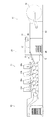
図1に示す印刷機は、給紙部20、印刷部30及び排紙部40を備えている。給紙部20は、フィーダーボード21を介して枚葉紙Sを印刷部30に供給することができる。なお、枚葉紙Sとは印刷可能なものであれば紙に限らず、フィルムやプラスチックなども含むものである。印刷部30は、給紙部20から供給される枚葉紙Sを印刷することができ、複数の印刷ユニット(ここでは4台の印刷ユニット30a〜30d)を備えている。また、排紙部40は、印刷部30にて印刷された印刷物を排紙することができる。この印刷機では、給紙部20から枚葉紙Sが印刷部30に供給され、当該供給された枚葉紙Sが印刷部30における各印刷ユニット30a〜30dにて印刷された後、当該印刷された印刷物が排紙部40にて排紙される。
The printing press shown in FIG. 1 includes a
給紙部20は複数の枚葉紙Sを収容することができるものであり、給紙台26に積載された枚葉紙Sのうち、上端の枚葉紙Sから1枚ずつフィーダーヘッド22により引き出し、フィーダーボード21を介して枚葉紙Sを印刷部30に向けて矢印Z方向に搬送することができるものである。これにより、枚葉紙Sを印刷部30に供給することができる。フィーダーヘッド22は後述するフィーダーヘッド用モータM3により、図1に示す進出位置と図2に示す退避位置との間を移動可能に構成されている。
The
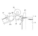
図3に示すように、給紙台26に積載される枚葉紙Sの搬送方向下流側にはフェンス25が設けられており、フェンス25は図3の実線で示す起立位置と、二点鎖線で示す倒伏位置との間を位置変更可能に往復動するよう構成されている。フェンス25は起立位置では枚葉紙Sの前端面に当接し、枚葉紙Sを規制するが、倒伏位置では規制しないので枚葉紙Sを一枚ずつ供給可能になっている。この倒伏位置で、後述するフィーダーヘッド22のサッカー28が枚葉紙Sを供給する。フェンス25は後述する、印刷機を駆動する本機モータM0によって往復回動する他、同じく後述するエアシリンダAの伸長動作により、本機モータM0の駆動に関係なく倒伏位置に固定されるようにもなっている。サッカー28は後述のクラッチC2を介して本機モータM0によって駆動する。
As shown in FIG. 3, a
また、給紙台26の搬送方向に直交する幅方向両側には一対のバーチカルガイド27が設けられている。バーチカルガイド27は給紙台26に積載された枚葉紙Pの幅方向の位置決めを行う進出位置と、枚葉紙Pから離間する退避位置との間を、バーチカルガイド用モータM5により移動可能に構成されている。
A pair of
フェンス25の倒伏位置で供給される枚葉紙Sを案内するフィードローラ23、24が設けられており、両者は回転しながら枚葉紙Sを前述のフィーダーボード21に案内する。符号29は落下防止片である。フィーダーボード21には送りテープ21aと送りローラ21bが設けられており、枚葉紙Sを案内しながら搬送する。送りローラ21b、フィードローラ23、24はクラッチC1を介して本機モータM0によって駆動する(図4参照)。なお、前述のクラッチC2はクラッチC1を介して本機モータM0に接続されており、クラッチC1、C2の両方が接続されることで、サッカー28が駆動する。
Feed
印刷部30の各印刷ユニット30a〜30dは、それぞれ版胴31、ゴム胴32及び圧胴33を主要構成要素の一組として構成されるものである。印刷ユニット30aにおける符号34aは給紙胴であり、印刷ユニット30b〜30dにおける34はいずれも渡し胴である。圧胴33には枚葉紙Sを挟持、搬送し、下流側の渡し胴34に受渡しをする図示しないグリッパ装置が設けられる。渡し胴34や給紙胴34aにも同様にグリッパ装置が設けられる。
Each of the
各印刷ユニット30a〜30dにおいて、版胴31には印刷用の版(図示を省略)が配設される。この版には図示しない、インキ供給部であるインキローラ群及び給水装置からインキ及び水が供給され、版に従ってインキがゴム胴32に転写される。そしてゴム胴32に転写されたインキがゴム胴32及び圧胴33間で搬送されてくる枚葉紙Sにさらに転写される。これにより、給紙部20から供給される枚葉紙Sに対してそれぞれに設けられた版に対応して印刷を行うことができる。
In each of the
また、給紙部20の枚葉紙搬送方向上流側にはロールフィーダ50が設けられている。ロールフィーダ50にはウェブ51がロール状にセットされており、本体52内には図示しないカッターと多数のローラが配置されており、ロールから繰り出され、本体52内で切断されたウェブ51は枚葉紙Sとなって搬送テーブル53上を搬送されるように構成されている。搬送テーブル53は図1に示す退避位置と図2に示す進出位置との間を回動可能に構成されている。搬送テーブル53の退避位置においては、後述するロールフィーダ用モータM4は駆動できないように構成されている。
A
図4は本発明に係る制御部80の構成を示す概略ブロック図である。制御部80は演算処理等を行うマイクロプロセッサ81(シーケンサでもよい)、データ及び所定のプログラム(演算式あるいはテーブル等)を記憶するROM82、機械回転数等に関する種々の情報を記憶可能なRAM83、マイクロプロセッサ81と制御部80外部に設けられた装置との間における各種信号のやりとりを仲介するインターフェイス84等を用いて構成されている。
FIG. 4 is a schematic block diagram showing the configuration of the
制御部80には、印刷機本体を駆動可能な本機モータM0、前述の給紙台26を昇降させる昇降モータM1、フェンス25を倒伏位置へ移動させるエアシリンダA、フィーダーヘッド22を移動させるフィーダーヘッド用モータM3、ロールフィーダ50を駆動可能なロールフィーダ用モータM4、バーチカルガイド27を移動させるバーチカルガイド用モータM5が接続されている。
The
制御部80には前述のクラッチC1及びC2も接続されている。このクラッチC1は給紙部20と本機モータM0とを接離するものであり、クラッチC1を切り離すことにより、給紙部20の各構成部品の駆動は停止する。クラッチC2はクラッチC1を介してサッカー28と本機モータM0とを接離するものである。クラッチC1は通常切り離されており(OFF)、本機モータM0による印刷機の駆動が開始され、所定速度に達したら接続される(ON)ようになっている。また、サッカー28はエア吸引により枚葉紙Pを吸着保持可能になっており、このエア吸引の駆動源であるポンプQも制御部80に接続されている。
The
また、制御部80には、給紙台26の下降端への移動を検知するセンサD1、フェンス25の倒伏位置への移動を検知するセンサD2、フィーダーヘッド22の退避位置への移動を検知するセンサD3、搬送テーブル53の進出位置において、搬送テーブル53の先端を検知するセンサD4、バーチカルガイド27の退避位置への移動を検知するセンサD5が接続されている。
The
本実施例の動作についてフローチャートを用いながら説明する。給紙部20を使用する場合、まず、搬送テーブル53を安全に退避させる必要がある。図5において、センサD1がONとなっているかが確認され(ステップS1)、給紙台26が下端にいなかったら下降させるべくモータM1を駆動させる(ステップS2)。次にセンサD5がONとなっているかが確認され(ステップS3)、バーチカルガイド27が退避位置にいなかったら、退避させるべくモータM5を駆動させる(ステップS4)。この状態で、搬送テーブル53が退避可能となるので、センサD4がOFFとなっているか(搬送テーブル53の進出を検知していないか)が確認され(ステップS5)、検知していたら搬送テーブル53を図示しない退避機構にて退避させる(ステップS6)。なお、報知手段により報知して、オペレータが手動で搬送テーブル53を退避させるようにしてもよい。こうすることにより、ロールフィーダ用モータM4は駆動できなくなる。
The operation of this embodiment will be described with reference to a flowchart. When using the
次にセンサD1がOFFとなっているかが確認され(ステップS7)、給紙台26が下端にいたら上昇させるべくモータM1を駆動させる(ステップS8)。次にセンサD2がOFFとなっているかが確認され(ステップS9)、フェンス25が倒伏位置にいたらエアシリンダAを退避させる(ステップS10)。次にセンサD3がOFFとなっているかが確認され(ステップS11)、フィーダーヘッド22が退避位置にいたら進出させるべくモータM3を駆動させる(ステップS12)。
Next, it is confirmed whether or not the sensor D1 is OFF (step S7), and the motor M1 is driven to raise the sheet feed table 26 when it is at the lower end (step S8). Next, it is confirmed whether or not the sensor D2 is OFF (step S9). When the
そしてセンサD5がOFFになっているかが確認され(ステップS13)、バーチカルガイド27が退避位置にいたら進出させるべくモータM5を駆動させる(ステップS14)。そしてクラッチC2をONする(ステップS15)ことによりルーチンが終了し、給紙部20を用いた印刷作業へ移行することとなる。印刷作業においては前述の通り、本機モータM0による印刷機の駆動速度が所定速度に達したら、クラッチC1を接続して枚葉紙Sの搬送を開始する。このように、給紙部20を使用する場合はロールフィーダ50が使用不能に制御され、かつ作業の邪魔にならないように退避位置に位置させる。
Then, it is confirmed whether the sensor D5 is OFF (step S13). When the
ロールフィーダ50を使用する場合、まず、搬送テーブル53を安全に進出させる必要がある。図6において、センサD1がONになっているかが確認され(ステップS21)、OFFになっている場合は給紙台26を下端に移動させるべくモータM1を駆動させる(ステップS22)。次にセンサD3がONになっているかが確認され(ステップS23)、OFFの場合、フィーダーヘッド22を退避させるべくモータM3を駆動させる(ステップS24)。そしてセンサD5がONになっているかが確認され(ステップS25)、OFFの場合、バーチカルガイド27を退避させるべくモータM5を駆動させる(ステップS26)。この状態で、搬送テーブル53が進出可能となるので、センサD4がONになっているかどうかが確認され(ステップS27)、OFFの場合、搬送テーブル53を図示しない進出機構にて進出させる(ステップS28)。なお、報知手段により報知して、オペレータが手動で搬送テーブル53を進出させるようにしてもよい。
When using the
次にセンサD2がONになっているかが確認され(ステップS29)、OFFの場合、フェンス25を倒伏させるべくエアシリンダAを伸長させる(ステップS30)。そしてクラッチC2がOFFになっているかが確認され(ステップS31)、ONの場合、クラッチをOFFさせてサッカー28の駆動を断つ(ステップS32)。最後にロールフィーダ用モータM4をONにして(ステップS33)ルーチンを終了し、ロールフィーダ50を用いた印刷作業へ移行することとなる。印刷作業においては前述の通り、本機モータM0による印刷機の駆動速度が所定速度に達したら、クラッチC1を接続して枚葉紙Sの搬送を開始する。このように、ロールフィーダ50を使用する場合は給紙部20が使用不能に制御され、かつ作業の邪魔にならないように退避位置に位置されるのである。
Next, it is confirmed whether or not the sensor D2 is turned on (step S29). If the sensor D2 is turned off, the air cylinder A is extended to fall the fence 25 (step S30). Then, it is confirmed whether or not the clutch C2 is turned off (step S31). If the clutch C2 is turned on, the clutch is turned off and the driving of the
尚、本発明は、前述の実施形態に限定されるものではなく、本発明の要旨を逸脱しない範囲で種々の変更が可能である。例えば、前述の実施形態では、バーチカルガイド27やフィーダーヘッド22を移動させるモータを別々に設けていたが、一つのモータでこれらを移動させてもよい。また、前述の動作順序についてはあくまで一例であり、任意の順序が選択可能である。全ての条件が整ってからクラッチコントロールを行うのである。
In addition, this invention is not limited to the above-mentioned embodiment, A various change is possible in the range which does not deviate from the summary of this invention. For example, in the above-described embodiment, the motor for moving the
また、前述の実施形態では、枚葉オフセット印刷機であったが、これに限定されず、ロールフィーダと給紙部とを使い分けるものであれば、液体トナー式印刷機やインクジェット式印刷機やグラビア印刷機やフレキソ印刷機のようなものであってもよい。 In the above-described embodiment, the sheet-fed offset printing machine is used. However, the present invention is not limited to this, and a liquid toner type printing machine, an ink jet type printing machine, or a gravure may be used as long as the roll feeder and the paper feeding unit are selectively used. It may be a printer or a flexographic printer.
本発明に係る印刷機は、ロールフィーダを接続可能な印刷機において極めて有用である。 The printer according to the present invention is extremely useful in a printer capable of connecting a roll feeder.
20…給紙部、21…フィーダーボード、25…フェンス、26…給紙台、27…バーチカルガイド、28…サッカー、30…印刷部、40…排紙部、50…ロールフィーダ、51…ウェブ、52…本体、53…搬送テーブル、80…制御部、C…クラッチ、D1,D2,D3,D4,D5…センサ、M0,M1,M2,M3,M4,M5…モータ、S…枚葉紙
DESCRIPTION OF
Claims (2)
枚葉紙の給紙を制御する制御部が設けられ、該制御部は該給紙部と該ロールフィーダのどちらか一方が使用される時に、どちらか他方を使用不能に制御することを特徴とする印刷機。 A sheet feeding unit capable of stacking sheets, a printing unit capable of printing a sheet supplied from the sheet feeding unit, and a sheet wound by cutting a web wound in a roll shape into a predetermined length And a roll feeder that discharges, and the roll feeder is provided so as to be able to contact and separate from the printing unit,
A control unit for controlling sheet feeding is provided, and the control unit controls one of the sheet feeding unit and the roll feeder to be disabled when one of the sheet feeding unit and the roll feeder is used. Printing machine to do.
Priority Applications (1)
| Application Number | Priority Date | Filing Date | Title |
|---|---|---|---|
| JP2013041637A JP2014169157A (en) | 2013-03-04 | 2013-03-04 | Printer |
Applications Claiming Priority (1)
| Application Number | Priority Date | Filing Date | Title |
|---|---|---|---|
| JP2013041637A JP2014169157A (en) | 2013-03-04 | 2013-03-04 | Printer |
Publications (1)
| Publication Number | Publication Date |
|---|---|
| JP2014169157A true JP2014169157A (en) | 2014-09-18 |
Family
ID=51691867
Family Applications (1)
| Application Number | Title | Priority Date | Filing Date |
|---|---|---|---|
| JP2013041637A Pending JP2014169157A (en) | 2013-03-04 | 2013-03-04 | Printer |
Country Status (1)
| Country | Link |
|---|---|
| JP (1) | JP2014169157A (en) |
Cited By (1)
| Publication number | Priority date | Publication date | Assignee | Title |
|---|---|---|---|---|
| CN115783831A (en) * | 2023-01-30 | 2023-03-14 | 苏州斯普兰蒂科技股份有限公司 | A loading attachment for silk screen printing machine |
Citations (4)
| Publication number | Priority date | Publication date | Assignee | Title |
|---|---|---|---|---|
| JPH03259825A (en) * | 1989-11-27 | 1991-11-19 | Mita Ind Co Ltd | Image forming device |
| JPH09150975A (en) * | 1995-09-08 | 1997-06-10 | Oce Nederland Bv | Device for stocking receiving material in printing unit |
| JPH10211742A (en) * | 1997-01-31 | 1998-08-11 | Brother Ind Ltd | Multifunctional printer |
| JP2003002468A (en) * | 2001-06-21 | 2003-01-08 | Kyocera Mita Corp | Image forming device |
-
2013
- 2013-03-04 JP JP2013041637A patent/JP2014169157A/en active Pending
Patent Citations (4)
| Publication number | Priority date | Publication date | Assignee | Title |
|---|---|---|---|---|
| JPH03259825A (en) * | 1989-11-27 | 1991-11-19 | Mita Ind Co Ltd | Image forming device |
| JPH09150975A (en) * | 1995-09-08 | 1997-06-10 | Oce Nederland Bv | Device for stocking receiving material in printing unit |
| JPH10211742A (en) * | 1997-01-31 | 1998-08-11 | Brother Ind Ltd | Multifunctional printer |
| JP2003002468A (en) * | 2001-06-21 | 2003-01-08 | Kyocera Mita Corp | Image forming device |
Cited By (1)
| Publication number | Priority date | Publication date | Assignee | Title |
|---|---|---|---|---|
| CN115783831A (en) * | 2023-01-30 | 2023-03-14 | 苏州斯普兰蒂科技股份有限公司 | A loading attachment for silk screen printing machine |
Similar Documents
| Publication | Publication Date | Title |
|---|---|---|
| US8876106B2 (en) | Recording device | |
| JP2003231244A (en) | Corrugated sheet printer | |
| JP2014169157A (en) | Printer | |
| JP6377728B2 (en) | Medium conveying apparatus and printing apparatus having the same | |
| KR101800879B1 (en) | Printing sheet transfer device of digital printing machine | |
| JP2008114594A (en) | Device and method for finish-processing sheet-like base material in sheet-fed press | |
| JP6621240B2 (en) | Paper turning device and printing device | |
| JP2007098739A (en) | Perfecting press | |
| JP2014148095A (en) | Method and device for transferring to printing paper | |
| JP2015160728A (en) | Printer | |
| JP2014214001A (en) | Printer | |
| JP2014213504A (en) | Sheet conveyance device | |
| JP2009161313A (en) | Double feed state detector of paper sheet printer | |
| JP2010042899A (en) | Paper discharge device and printer | |
| JP2011162320A (en) | Paper feeding unit of printing device | |
| JP5763421B2 (en) | Paper feeder and printing machine | |
| JP6468685B2 (en) | Sheet-fed printing machine | |
| JP2020011800A (en) | Printer | |
| JP6132619B2 (en) | Image forming system | |
| JP2012210993A (en) | Paper feeder and printing machine | |
| JP2017075039A (en) | Sheet transport device | |
| JP5763448B2 (en) | Paper feeder and printing machine | |
| JP5147671B2 (en) | Printing apparatus and plate making method of printing apparatus | |
| JP5714147B1 (en) | Printing device | |
| JP2006347718A (en) | Sheet-like article conveying device and its conveying method |
Legal Events
| Date | Code | Title | Description |
|---|---|---|---|
| A621 | Written request for application examination |
Free format text: JAPANESE INTERMEDIATE CODE: A621 Effective date: 20151110 |
|
| A977 | Report on retrieval |
Free format text: JAPANESE INTERMEDIATE CODE: A971007 Effective date: 20160622 |
|
| A131 | Notification of reasons for refusal |
Free format text: JAPANESE INTERMEDIATE CODE: A131 Effective date: 20160624 |
|
| A02 | Decision of refusal |
Free format text: JAPANESE INTERMEDIATE CODE: A02 Effective date: 20161228 |