JP2014160656A - Lithium secondary battery anode and manufacturing method thereof, and lithium air battery including the same - Google Patents
Lithium secondary battery anode and manufacturing method thereof, and lithium air battery including the same Download PDFInfo
- Publication number
- JP2014160656A JP2014160656A JP2014030191A JP2014030191A JP2014160656A JP 2014160656 A JP2014160656 A JP 2014160656A JP 2014030191 A JP2014030191 A JP 2014030191A JP 2014030191 A JP2014030191 A JP 2014030191A JP 2014160656 A JP2014160656 A JP 2014160656A
- Authority
- JP
- Japan
- Prior art keywords
- lithium
- negative electrode
- secondary battery
- lithium secondary
- housing
- Prior art date
- Legal status (The legal status is an assumption and is not a legal conclusion. Google has not performed a legal analysis and makes no representation as to the accuracy of the status listed.)
- Granted
Links
- 229910052744 lithium Inorganic materials 0.000 title claims abstract description 168
- WHXSMMKQMYFTQS-UHFFFAOYSA-N Lithium Chemical compound [Li] WHXSMMKQMYFTQS-UHFFFAOYSA-N 0.000 title claims abstract description 114
- 238000004519 manufacturing process Methods 0.000 title claims abstract description 25
- 238000000034 method Methods 0.000 claims abstract description 17
- 239000007784 solid electrolyte Substances 0.000 claims description 48
- 238000007789 sealing Methods 0.000 claims description 38
- 239000003792 electrolyte Substances 0.000 claims description 36
- 238000009792 diffusion process Methods 0.000 claims description 21
- 239000003054 catalyst Substances 0.000 claims description 16
- 230000002093 peripheral effect Effects 0.000 claims description 16
- 238000003466 welding Methods 0.000 claims description 15
- PXHVJJICTQNCMI-UHFFFAOYSA-N Nickel Chemical compound [Ni] PXHVJJICTQNCMI-UHFFFAOYSA-N 0.000 claims description 12
- 239000010949 copper Substances 0.000 claims description 12
- 230000000149 penetrating effect Effects 0.000 claims description 11
- 239000002608 ionic liquid Substances 0.000 claims description 10
- 238000010030 laminating Methods 0.000 claims description 10
- 239000003795 chemical substances by application Substances 0.000 claims description 8
- 229910052802 copper Inorganic materials 0.000 claims description 7
- RYGMFSIKBFXOCR-UHFFFAOYSA-N Copper Chemical compound [Cu] RYGMFSIKBFXOCR-UHFFFAOYSA-N 0.000 claims description 6
- 239000000853 adhesive Substances 0.000 claims description 6
- 230000001070 adhesive effect Effects 0.000 claims description 6
- 239000005486 organic electrolyte Substances 0.000 claims description 6
- 239000000565 sealant Substances 0.000 claims description 6
- 239000011248 coating agent Substances 0.000 claims description 5
- 238000000576 coating method Methods 0.000 claims description 5
- 239000000463 material Substances 0.000 claims description 5
- 229910052759 nickel Inorganic materials 0.000 claims description 5
- 238000003825 pressing Methods 0.000 claims description 5
- 238000005219 brazing Methods 0.000 claims description 4
- 238000005476 soldering Methods 0.000 claims description 4
- 238000004078 waterproofing Methods 0.000 claims description 3
- HBBGRARXTFLTSG-UHFFFAOYSA-N Lithium ion Chemical compound [Li+] HBBGRARXTFLTSG-UHFFFAOYSA-N 0.000 abstract description 22
- 229910001416 lithium ion Inorganic materials 0.000 abstract description 22
- MYMOFIZGZYHOMD-UHFFFAOYSA-N Dioxygen Chemical compound O=O MYMOFIZGZYHOMD-UHFFFAOYSA-N 0.000 abstract description 5
- UFHFLCQGNIYNRP-UHFFFAOYSA-N Hydrogen Chemical compound [H][H] UFHFLCQGNIYNRP-UHFFFAOYSA-N 0.000 abstract description 5
- 229910001882 dioxygen Inorganic materials 0.000 abstract description 5
- 230000007797 corrosion Effects 0.000 abstract description 2
- 238000005260 corrosion Methods 0.000 abstract description 2
- -1 pyrazolium ion Chemical class 0.000 description 26
- 230000008878 coupling Effects 0.000 description 17
- 238000010168 coupling process Methods 0.000 description 17
- 238000005859 coupling reaction Methods 0.000 description 17
- 239000007789 gas Substances 0.000 description 17
- QVGXLLKOCUKJST-UHFFFAOYSA-N atomic oxygen Chemical compound [O] QVGXLLKOCUKJST-UHFFFAOYSA-N 0.000 description 11
- 229910052760 oxygen Inorganic materials 0.000 description 11
- 239000001301 oxygen Substances 0.000 description 11
- 239000000126 substance Substances 0.000 description 11
- 125000000217 alkyl group Chemical group 0.000 description 6
- 239000011230 binding agent Substances 0.000 description 6
- 238000006243 chemical reaction Methods 0.000 description 6
- OKTJSMMVPCPJKN-UHFFFAOYSA-N Carbon Chemical compound [C] OKTJSMMVPCPJKN-UHFFFAOYSA-N 0.000 description 5
- 239000004020 conductor Substances 0.000 description 5
- 229910052751 metal Inorganic materials 0.000 description 5
- 239000002184 metal Substances 0.000 description 5
- 125000003342 alkenyl group Chemical group 0.000 description 4
- 125000003545 alkoxy group Chemical group 0.000 description 4
- 150000003949 imides Chemical class 0.000 description 4
- KWGKDLIKAYFUFQ-UHFFFAOYSA-M lithium chloride Chemical compound [Li+].[Cl-] KWGKDLIKAYFUFQ-UHFFFAOYSA-M 0.000 description 4
- 229910003002 lithium salt Inorganic materials 0.000 description 4
- 159000000002 lithium salts Chemical class 0.000 description 4
- ZXMGHDIOOHOAAE-UHFFFAOYSA-N 1,1,1-trifluoro-n-(trifluoromethylsulfonyl)methanesulfonamide Chemical compound FC(F)(F)S(=O)(=O)NS(=O)(=O)C(F)(F)F ZXMGHDIOOHOAAE-UHFFFAOYSA-N 0.000 description 3
- ZWEHNKRNPOVVGH-UHFFFAOYSA-N 2-Butanone Chemical compound CCC(C)=O ZWEHNKRNPOVVGH-UHFFFAOYSA-N 0.000 description 3
- CSCPPACGZOOCGX-UHFFFAOYSA-N Acetone Chemical compound CC(C)=O CSCPPACGZOOCGX-UHFFFAOYSA-N 0.000 description 3
- 239000011149 active material Substances 0.000 description 3
- 150000001875 compounds Chemical class 0.000 description 3
- 230000006866 deterioration Effects 0.000 description 3
- 229910052736 halogen Inorganic materials 0.000 description 3
- 229910052739 hydrogen Inorganic materials 0.000 description 3
- 239000001257 hydrogen Substances 0.000 description 3
- 238000012423 maintenance Methods 0.000 description 3
- KTQDYGVEEFGIIL-UHFFFAOYSA-N n-fluorosulfonylsulfamoyl fluoride Chemical compound FS(=O)(=O)NS(F)(=O)=O KTQDYGVEEFGIIL-UHFFFAOYSA-N 0.000 description 3
- BASFCYQUMIYNBI-UHFFFAOYSA-N platinum Chemical compound [Pt] BASFCYQUMIYNBI-UHFFFAOYSA-N 0.000 description 3
- 229920001296 polysiloxane Polymers 0.000 description 3
- 238000006479 redox reaction Methods 0.000 description 3
- 238000003860 storage Methods 0.000 description 3
- 125000003837 (C1-C20) alkyl group Chemical group 0.000 description 2
- 125000006649 (C2-C20) alkynyl group Chemical group 0.000 description 2
- YTSDTJNDMGOTFN-UHFFFAOYSA-M 1-butyl-4-methylpyridin-1-ium;chloride Chemical compound [Cl-].CCCC[N+]1=CC=C(C)C=C1 YTSDTJNDMGOTFN-UHFFFAOYSA-M 0.000 description 2
- NJMWOUFKYKNWDW-UHFFFAOYSA-N 1-ethyl-3-methylimidazolium Chemical compound CCN1C=C[N+](C)=C1 NJMWOUFKYKNWDW-UHFFFAOYSA-N 0.000 description 2
- CURLTUGMZLYLDI-UHFFFAOYSA-N Carbon dioxide Chemical compound O=C=O CURLTUGMZLYLDI-UHFFFAOYSA-N 0.000 description 2
- VEXZGXHMUGYJMC-UHFFFAOYSA-M Chloride anion Chemical compound [Cl-] VEXZGXHMUGYJMC-UHFFFAOYSA-M 0.000 description 2
- OIFBSDVPJOWBCH-UHFFFAOYSA-N Diethyl carbonate Chemical compound CCOC(=O)OCC OIFBSDVPJOWBCH-UHFFFAOYSA-N 0.000 description 2
- KMTRUDSVKNLOMY-UHFFFAOYSA-N Ethylene carbonate Chemical compound O=C1OCCO1 KMTRUDSVKNLOMY-UHFFFAOYSA-N 0.000 description 2
- 229910010238 LiAlCl 4 Inorganic materials 0.000 description 2
- 229910010093 LiAlO Inorganic materials 0.000 description 2
- 229910015015 LiAsF 6 Inorganic materials 0.000 description 2
- 229910013063 LiBF 4 Inorganic materials 0.000 description 2
- 229910013372 LiC 4 Inorganic materials 0.000 description 2
- 229910013684 LiClO 4 Inorganic materials 0.000 description 2
- 229910013131 LiN Inorganic materials 0.000 description 2
- 229910013870 LiPF 6 Inorganic materials 0.000 description 2
- 229910012513 LiSbF 6 Inorganic materials 0.000 description 2
- SECXISVLQFMRJM-UHFFFAOYSA-N N-Methylpyrrolidone Chemical compound CN1CCCC1=O SECXISVLQFMRJM-UHFFFAOYSA-N 0.000 description 2
- 239000002033 PVDF binder Substances 0.000 description 2
- 125000000304 alkynyl group Chemical group 0.000 description 2
- 239000003575 carbonaceous material Substances 0.000 description 2
- 125000003178 carboxy group Chemical group [H]OC(*)=O 0.000 description 2
- 150000001768 cations Chemical class 0.000 description 2
- 239000000835 fiber Substances 0.000 description 2
- 239000011888 foil Substances 0.000 description 2
- 150000002367 halogens Chemical class 0.000 description 2
- 238000005304 joining Methods 0.000 description 2
- AMXOYNBUYSYVKV-UHFFFAOYSA-M lithium bromide Chemical compound [Li+].[Br-] AMXOYNBUYSYVKV-UHFFFAOYSA-M 0.000 description 2
- PQXKHYXIUOZZFA-UHFFFAOYSA-M lithium fluoride Chemical compound [Li+].[F-] PQXKHYXIUOZZFA-UHFFFAOYSA-M 0.000 description 2
- 238000002844 melting Methods 0.000 description 2
- 230000008018 melting Effects 0.000 description 2
- VNWKTOKETHGBQD-UHFFFAOYSA-N methane Chemical compound C VNWKTOKETHGBQD-UHFFFAOYSA-N 0.000 description 2
- 238000002156 mixing Methods 0.000 description 2
- 239000003960 organic solvent Substances 0.000 description 2
- 230000035515 penetration Effects 0.000 description 2
- 229920001343 polytetrafluoroethylene Polymers 0.000 description 2
- 239000004810 polytetrafluoroethylene Substances 0.000 description 2
- 229920002981 polyvinylidene fluoride Polymers 0.000 description 2
- RUOJZAUFBMNUDX-UHFFFAOYSA-N propylene carbonate Chemical compound CC1COC(=O)O1 RUOJZAUFBMNUDX-UHFFFAOYSA-N 0.000 description 2
- 125000006527 (C1-C5) alkyl group Chemical group 0.000 description 1
- GSGLHYXFTXGIAQ-UHFFFAOYSA-M 1,3-dimethylimidazol-1-ium;dimethyl phosphate Chemical compound COP([O-])(=O)OC.CN1C=C[N+](C)=C1 GSGLHYXFTXGIAQ-UHFFFAOYSA-M 0.000 description 1
- COSSPXYCRNRXRX-UHFFFAOYSA-N 1-benzyl-3-methylimidazol-3-ium Chemical compound C1=[N+](C)C=CN1CC1=CC=CC=C1 COSSPXYCRNRXRX-UHFFFAOYSA-N 0.000 description 1
- PXELHGDYRQLRQO-UHFFFAOYSA-N 1-butyl-1-methylpyrrolidin-1-ium Chemical compound CCCC[N+]1(C)CCCC1 PXELHGDYRQLRQO-UHFFFAOYSA-N 0.000 description 1
- LCZRPQGSMFXSTC-UHFFFAOYSA-M 1-butyl-1-methylpyrrolidin-1-ium;bromide Chemical compound [Br-].CCCC[N+]1(C)CCCC1 LCZRPQGSMFXSTC-UHFFFAOYSA-M 0.000 description 1
- BOOXKGZZTBKJFE-UHFFFAOYSA-M 1-butyl-1-methylpyrrolidin-1-ium;chloride Chemical compound [Cl-].CCCC[N+]1(C)CCCC1 BOOXKGZZTBKJFE-UHFFFAOYSA-M 0.000 description 1
- FHDQNOXQSTVAIC-UHFFFAOYSA-M 1-butyl-3-methylimidazol-3-ium;chloride Chemical compound [Cl-].CCCCN1C=C[N+](C)=C1 FHDQNOXQSTVAIC-UHFFFAOYSA-M 0.000 description 1
- NTXQJRGQUZXUMU-UHFFFAOYSA-M 1-butyl-3-methylimidazol-3-ium;dibutyl phosphate Chemical compound CCCC[N+]=1C=CN(C)C=1.CCCCOP([O-])(=O)OCCCC NTXQJRGQUZXUMU-UHFFFAOYSA-M 0.000 description 1
- KXCVJPJCRAEILX-UHFFFAOYSA-M 1-butyl-3-methylimidazol-3-ium;hydrogen sulfate Chemical compound OS([O-])(=O)=O.CCCCN1C=C[N+](C)=C1 KXCVJPJCRAEILX-UHFFFAOYSA-M 0.000 description 1
- SXUPLFPGMYCSME-UHFFFAOYSA-M 1-butyl-3-methylimidazol-3-ium;hydron;carbonate Chemical compound OC([O-])=O.CCCC[N+]=1C=CN(C)C=1 SXUPLFPGMYCSME-UHFFFAOYSA-M 0.000 description 1
- MEMNKNZDROKJHP-UHFFFAOYSA-M 1-butyl-3-methylimidazol-3-ium;methyl sulfate Chemical compound COS([O-])(=O)=O.CCCCN1C=C[N+](C)=C1 MEMNKNZDROKJHP-UHFFFAOYSA-M 0.000 description 1
- SIXHYMZEOJSYQH-UHFFFAOYSA-M 1-butyl-3-methylimidazol-3-ium;thiocyanate Chemical compound [S-]C#N.CCCCN1C=C[N+](C)=C1 SIXHYMZEOJSYQH-UHFFFAOYSA-M 0.000 description 1
- IQQRAVYLUAZUGX-UHFFFAOYSA-N 1-butyl-3-methylimidazolium Chemical compound CCCCN1C=C[N+](C)=C1 IQQRAVYLUAZUGX-UHFFFAOYSA-N 0.000 description 1
- RQVJLVQTNZVVRZ-UHFFFAOYSA-M 1-dodecyl-3-methylimidazol-3-ium;iodide Chemical compound [I-].CCCCCCCCCCCCN1C=C[N+](C)=C1 RQVJLVQTNZVVRZ-UHFFFAOYSA-M 0.000 description 1
- NUJYCYLTUXYHQU-UHFFFAOYSA-M 1-ethyl-2,3-dimethylimidazol-3-ium;chloride Chemical compound [Cl-].CCN1C=C[N+](C)=C1C NUJYCYLTUXYHQU-UHFFFAOYSA-M 0.000 description 1
- OSCREXKVIJBLHA-UHFFFAOYSA-M 1-ethyl-2,3-dimethylimidazol-3-ium;ethyl sulfate Chemical compound CCOS([O-])(=O)=O.CCN1C=C[N+](C)=C1C OSCREXKVIJBLHA-UHFFFAOYSA-M 0.000 description 1
- GWQYPLXGJIXMMV-UHFFFAOYSA-M 1-ethyl-3-methylimidazol-3-ium;bromide Chemical compound [Br-].CCN1C=C[N+](C)=C1 GWQYPLXGJIXMMV-UHFFFAOYSA-M 0.000 description 1
- BMQZYMYBQZGEEY-UHFFFAOYSA-M 1-ethyl-3-methylimidazolium chloride Chemical compound [Cl-].CCN1C=C[N+](C)=C1 BMQZYMYBQZGEEY-UHFFFAOYSA-M 0.000 description 1
- YQFWGCSKGJMGHE-UHFFFAOYSA-N 1-methyl-1-propylpyrrolidin-1-ium Chemical compound CCC[N+]1(C)CCCC1 YQFWGCSKGJMGHE-UHFFFAOYSA-N 0.000 description 1
- WVDDUSFOSWWJJH-UHFFFAOYSA-N 1-methyl-3-propylimidazol-1-ium Chemical compound CCCN1C=C[N+](C)=C1 WVDDUSFOSWWJJH-UHFFFAOYSA-N 0.000 description 1
- SNXTZFCNWIVLKZ-UHFFFAOYSA-M 4-methylbenzenesulfonate;methyl-tris(2-methylpropyl)phosphanium Chemical compound CC1=CC=C(S([O-])(=O)=O)C=C1.CC(C)C[P+](C)(CC(C)C)CC(C)C SNXTZFCNWIVLKZ-UHFFFAOYSA-M 0.000 description 1
- 229910016467 AlCl 4 Inorganic materials 0.000 description 1
- QGZKDVFQNNGYKY-UHFFFAOYSA-O Ammonium Chemical compound [NH4+] QGZKDVFQNNGYKY-UHFFFAOYSA-O 0.000 description 1
- BTBUEUYNUDRHOZ-UHFFFAOYSA-N Borate Chemical compound [O-]B([O-])[O-] BTBUEUYNUDRHOZ-UHFFFAOYSA-N 0.000 description 1
- PAZSRSJHAQYUPS-UHFFFAOYSA-M C(#N)[N-]C#N.C(CCC)[N+]1=CN(C=C1)C.P(=O)(OCCCC)(OCCCC)[O-].C(CCC)[N+]1=CN(C=C1)C Chemical compound C(#N)[N-]C#N.C(CCC)[N+]1=CN(C=C1)C.P(=O)(OCCCC)(OCCCC)[O-].C(CCC)[N+]1=CN(C=C1)C PAZSRSJHAQYUPS-UHFFFAOYSA-M 0.000 description 1
- 229920000049 Carbon (fiber) Polymers 0.000 description 1
- RAXXELZNTBOGNW-UHFFFAOYSA-O Imidazolium Chemical compound C1=C[NH+]=CN1 RAXXELZNTBOGNW-UHFFFAOYSA-O 0.000 description 1
- 229910018071 Li 2 O 2 Inorganic materials 0.000 description 1
- 229910000733 Li alloy Inorganic materials 0.000 description 1
- 229910015044 LiB Inorganic materials 0.000 description 1
- 229910013188 LiBOB Inorganic materials 0.000 description 1
- 229910013385 LiN(SO2C2F5)2 Inorganic materials 0.000 description 1
- 229920000265 Polyparaphenylene Polymers 0.000 description 1
- RWRDLPDLKQPQOW-UHFFFAOYSA-O Pyrrolidinium ion Chemical compound C1CC[NH2+]C1 RWRDLPDLKQPQOW-UHFFFAOYSA-O 0.000 description 1
- 229910018286 SbF 6 Inorganic materials 0.000 description 1
- BQCADISMDOOEFD-UHFFFAOYSA-N Silver Chemical compound [Ag] BQCADISMDOOEFD-UHFFFAOYSA-N 0.000 description 1
- FBGDOTMIIARWDL-UHFFFAOYSA-K [Al+3].[Cl-].[Cl-].[Cl-].CC[n+]1ccn(C)c1 Chemical compound [Al+3].[Cl-].[Cl-].[Cl-].CC[n+]1ccn(C)c1 FBGDOTMIIARWDL-UHFFFAOYSA-K 0.000 description 1
- 239000000956 alloy Substances 0.000 description 1
- 229910045601 alloy Inorganic materials 0.000 description 1
- 229910052782 aluminium Inorganic materials 0.000 description 1
- XAGFODPZIPBFFR-UHFFFAOYSA-N aluminium Chemical compound [Al] XAGFODPZIPBFFR-UHFFFAOYSA-N 0.000 description 1
- VSCWAEJMTAWNJL-UHFFFAOYSA-K aluminum chloride Substances Cl[Al](Cl)Cl VSCWAEJMTAWNJL-UHFFFAOYSA-K 0.000 description 1
- PNOZWIUFLYBVHH-UHFFFAOYSA-J aluminum;1-butyl-3-methylimidazol-3-ium;tetrachloride Chemical compound [Cl-].Cl[Al](Cl)Cl.CCCCN1C=C[N+](C)=C1 PNOZWIUFLYBVHH-UHFFFAOYSA-J 0.000 description 1
- 150000001450 anions Chemical class 0.000 description 1
- DKNRELLLVOYIIB-UHFFFAOYSA-N bis(trifluoromethylsulfonyl)azanide;1-methyl-1-propylpyrrolidin-1-ium Chemical compound CCC[N+]1(C)CCCC1.FC(F)(F)S(=O)(=O)[N-]S(=O)(=O)C(F)(F)F DKNRELLLVOYIIB-UHFFFAOYSA-N 0.000 description 1
- CDWUIWLQQDTHRA-UHFFFAOYSA-N bis(trifluoromethylsulfonyl)azanide;1-methyl-3-propylimidazol-1-ium Chemical compound CCCN1C=C[N+](C)=C1.FC(F)(F)S(=O)(=O)[N-]S(=O)(=O)C(F)(F)F CDWUIWLQQDTHRA-UHFFFAOYSA-N 0.000 description 1
- NNNHNBMBLGKXSW-UHFFFAOYSA-N bis(trifluoromethylsulfonyl)azanide;4-(3-methylimidazol-3-ium-1-yl)butanenitrile Chemical compound C[N+]=1C=CN(CCCC#N)C=1.FC(F)(F)S(=O)(=O)[N-]S(=O)(=O)C(F)(F)F NNNHNBMBLGKXSW-UHFFFAOYSA-N 0.000 description 1
- 229910052799 carbon Inorganic materials 0.000 description 1
- 239000006229 carbon black Substances 0.000 description 1
- 229910002092 carbon dioxide Inorganic materials 0.000 description 1
- 239000001569 carbon dioxide Substances 0.000 description 1
- 239000004917 carbon fiber Substances 0.000 description 1
- 229910021393 carbon nanotube Inorganic materials 0.000 description 1
- 239000002041 carbon nanotube Substances 0.000 description 1
- 239000000919 ceramic Substances 0.000 description 1
- 229910010293 ceramic material Inorganic materials 0.000 description 1
- 239000010779 crude oil Substances 0.000 description 1
- IEJIGPNLZYLLBP-UHFFFAOYSA-N dimethyl carbonate Chemical compound COC(=O)OC IEJIGPNLZYLLBP-UHFFFAOYSA-N 0.000 description 1
- LVVSOUMZHQUECI-UHFFFAOYSA-N dimethyl(1-phenylpentadecan-2-yl)alumane Chemical compound CCCCCCCCCCCCCC([Al](C)C)CC1=CC=CC=C1 LVVSOUMZHQUECI-UHFFFAOYSA-N 0.000 description 1
- 238000003618 dip coating Methods 0.000 description 1
- 230000001747 exhibiting effect Effects 0.000 description 1
- 239000002803 fossil fuel Substances 0.000 description 1
- 239000003502 gasoline Substances 0.000 description 1
- 239000010439 graphite Substances 0.000 description 1
- 229910002804 graphite Inorganic materials 0.000 description 1
- 238000007756 gravure coating Methods 0.000 description 1
- 125000002887 hydroxy group Chemical group [H]O* 0.000 description 1
- 230000002401 inhibitory effect Effects 0.000 description 1
- 238000009830 intercalation Methods 0.000 description 1
- 230000016507 interphase Effects 0.000 description 1
- 150000008040 ionic compounds Chemical class 0.000 description 1
- 150000002500 ions Chemical class 0.000 description 1
- 239000001989 lithium alloy Substances 0.000 description 1
- HSZCZNFXUDYRKD-UHFFFAOYSA-M lithium iodide Inorganic materials [Li+].[I-] HSZCZNFXUDYRKD-UHFFFAOYSA-M 0.000 description 1
- 239000000203 mixture Substances 0.000 description 1
- 238000012986 modification Methods 0.000 description 1
- 230000004048 modification Effects 0.000 description 1
- 125000004108 n-butyl group Chemical group [H]C([H])([H])C([H])([H])C([H])([H])C([H])([H])* 0.000 description 1
- 239000003921 oil Substances 0.000 description 1
- 239000011301 petroleum pitch Substances 0.000 description 1
- 229910052697 platinum Inorganic materials 0.000 description 1
- 239000000843 powder Substances 0.000 description 1
- 125000002924 primary amino group Chemical group [H]N([H])* 0.000 description 1
- JUJWROOIHBZHMG-UHFFFAOYSA-O pyridinium Chemical compound C1=CC=[NH+]C=C1 JUJWROOIHBZHMG-UHFFFAOYSA-O 0.000 description 1
- 239000013464 silicone adhesive Substances 0.000 description 1
- 229910052709 silver Inorganic materials 0.000 description 1
- 239000004332 silver Substances 0.000 description 1
- 239000002002 slurry Substances 0.000 description 1
- 239000007787 solid Substances 0.000 description 1
- 239000002904 solvent Substances 0.000 description 1
- RWSOTUBLDIXVET-UHFFFAOYSA-O sulfonium Chemical compound [SH3+] RWSOTUBLDIXVET-UHFFFAOYSA-O 0.000 description 1
- 229920003002 synthetic resin Polymers 0.000 description 1
- 239000000057 synthetic resin Substances 0.000 description 1
- IBWGNZVCJVLSHB-UHFFFAOYSA-M tetrabutylphosphanium;chloride Chemical compound [Cl-].CCCC[P+](CCCC)(CCCC)CCCC IBWGNZVCJVLSHB-UHFFFAOYSA-M 0.000 description 1
- VMJQVRWCDVLJSI-UHFFFAOYSA-M tetraheptylazanium;chloride Chemical compound [Cl-].CCCCCCC[N+](CCCCCCC)(CCCCCCC)CCCCCCC VMJQVRWCDVLJSI-UHFFFAOYSA-M 0.000 description 1
- VRKHAMWCGMJAMI-UHFFFAOYSA-M tetrahexylazanium;iodide Chemical compound [I-].CCCCCC[N+](CCCCCC)(CCCCCC)CCCCCC VRKHAMWCGMJAMI-UHFFFAOYSA-M 0.000 description 1
- AHNISXOXSNAHBZ-UHFFFAOYSA-M tetrakis-decylazanium;bromide Chemical compound [Br-].CCCCCCCCCC[N+](CCCCCCCCCC)(CCCCCCCCCC)CCCCCCCCCC AHNISXOXSNAHBZ-UHFFFAOYSA-M 0.000 description 1
- IPILPUZVTYHGIL-UHFFFAOYSA-M tributyl(methyl)azanium;chloride Chemical compound [Cl-].CCCC[N+](C)(CCCC)CCCC IPILPUZVTYHGIL-UHFFFAOYSA-M 0.000 description 1
- 125000002023 trifluoromethyl group Chemical group FC(F)(F)* 0.000 description 1
- 239000011800 void material Substances 0.000 description 1
- XLYOFNOQVPJJNP-UHFFFAOYSA-N water Substances O XLYOFNOQVPJJNP-UHFFFAOYSA-N 0.000 description 1
Images


Classifications
-
- H—ELECTRICITY
- H01—ELECTRIC ELEMENTS
- H01M—PROCESSES OR MEANS, e.g. BATTERIES, FOR THE DIRECT CONVERSION OF CHEMICAL ENERGY INTO ELECTRICAL ENERGY
- H01M12/00—Hybrid cells; Manufacture thereof
- H01M12/08—Hybrid cells; Manufacture thereof composed of a half-cell of a fuel-cell type and a half-cell of the secondary-cell type
-
- H—ELECTRICITY
- H01—ELECTRIC ELEMENTS
- H01M—PROCESSES OR MEANS, e.g. BATTERIES, FOR THE DIRECT CONVERSION OF CHEMICAL ENERGY INTO ELECTRICAL ENERGY
- H01M4/00—Electrodes
- H01M4/02—Electrodes composed of, or comprising, active material
- H01M4/13—Electrodes for accumulators with non-aqueous electrolyte, e.g. for lithium-accumulators; Processes of manufacture thereof
-
- H—ELECTRICITY
- H01—ELECTRIC ELEMENTS
- H01M—PROCESSES OR MEANS, e.g. BATTERIES, FOR THE DIRECT CONVERSION OF CHEMICAL ENERGY INTO ELECTRICAL ENERGY
- H01M12/00—Hybrid cells; Manufacture thereof
- H01M12/04—Hybrid cells; Manufacture thereof composed of a half-cell of the fuel-cell type and of a half-cell of the primary-cell type
- H01M12/06—Hybrid cells; Manufacture thereof composed of a half-cell of the fuel-cell type and of a half-cell of the primary-cell type with one metallic and one gaseous electrode
-
- H—ELECTRICITY
- H01—ELECTRIC ELEMENTS
- H01M—PROCESSES OR MEANS, e.g. BATTERIES, FOR THE DIRECT CONVERSION OF CHEMICAL ENERGY INTO ELECTRICAL ENERGY
- H01M4/00—Electrodes
- H01M4/02—Electrodes composed of, or comprising, active material
- H01M4/04—Processes of manufacture in general
- H01M4/043—Processes of manufacture in general involving compressing or compaction
-
- H—ELECTRICITY
- H01—ELECTRIC ELEMENTS
- H01M—PROCESSES OR MEANS, e.g. BATTERIES, FOR THE DIRECT CONVERSION OF CHEMICAL ENERGY INTO ELECTRICAL ENERGY
- H01M4/00—Electrodes
- H01M4/02—Electrodes composed of, or comprising, active material
- H01M4/13—Electrodes for accumulators with non-aqueous electrolyte, e.g. for lithium-accumulators; Processes of manufacture thereof
- H01M4/134—Electrodes based on metals, Si or alloys
-
- H—ELECTRICITY
- H01—ELECTRIC ELEMENTS
- H01M—PROCESSES OR MEANS, e.g. BATTERIES, FOR THE DIRECT CONVERSION OF CHEMICAL ENERGY INTO ELECTRICAL ENERGY
- H01M4/00—Electrodes
- H01M4/02—Electrodes composed of, or comprising, active material
- H01M4/13—Electrodes for accumulators with non-aqueous electrolyte, e.g. for lithium-accumulators; Processes of manufacture thereof
- H01M4/139—Processes of manufacture
- H01M4/1395—Processes of manufacture of electrodes based on metals, Si or alloys
-
- H—ELECTRICITY
- H01—ELECTRIC ELEMENTS
- H01M—PROCESSES OR MEANS, e.g. BATTERIES, FOR THE DIRECT CONVERSION OF CHEMICAL ENERGY INTO ELECTRICAL ENERGY
- H01M4/00—Electrodes
- H01M4/02—Electrodes composed of, or comprising, active material
- H01M4/36—Selection of substances as active materials, active masses, active liquids
- H01M4/362—Composites
- H01M4/366—Composites as layered products
-
- H—ELECTRICITY
- H01—ELECTRIC ELEMENTS
- H01M—PROCESSES OR MEANS, e.g. BATTERIES, FOR THE DIRECT CONVERSION OF CHEMICAL ENERGY INTO ELECTRICAL ENERGY
- H01M4/00—Electrodes
- H01M4/02—Electrodes composed of, or comprising, active material
- H01M4/36—Selection of substances as active materials, active masses, active liquids
- H01M4/38—Selection of substances as active materials, active masses, active liquids of elements or alloys
- H01M4/381—Alkaline or alkaline earth metals elements
- H01M4/382—Lithium
-
- H—ELECTRICITY
- H01—ELECTRIC ELEMENTS
- H01M—PROCESSES OR MEANS, e.g. BATTERIES, FOR THE DIRECT CONVERSION OF CHEMICAL ENERGY INTO ELECTRICAL ENERGY
- H01M4/00—Electrodes
- H01M4/02—Electrodes composed of, or comprising, active material
- H01M4/64—Carriers or collectors
- H01M4/66—Selection of materials
- H01M4/661—Metal or alloys, e.g. alloy coatings
-
- H—ELECTRICITY
- H01—ELECTRIC ELEMENTS
- H01M—PROCESSES OR MEANS, e.g. BATTERIES, FOR THE DIRECT CONVERSION OF CHEMICAL ENERGY INTO ELECTRICAL ENERGY
- H01M4/00—Electrodes
- H01M4/02—Electrodes composed of, or comprising, active material
- H01M4/64—Carriers or collectors
- H01M4/70—Carriers or collectors characterised by shape or form
-
- H—ELECTRICITY
- H01—ELECTRIC ELEMENTS
- H01M—PROCESSES OR MEANS, e.g. BATTERIES, FOR THE DIRECT CONVERSION OF CHEMICAL ENERGY INTO ELECTRICAL ENERGY
- H01M50/00—Constructional details or processes of manufacture of the non-active parts of electrochemical cells other than fuel cells, e.g. hybrid cells
- H01M50/10—Primary casings, jackets or wrappings of a single cell or a single battery
- H01M50/138—Primary casings, jackets or wrappings of a single cell or a single battery adapted for specific cells, e.g. electrochemical cells operating at high temperature
- H01M50/1385—Hybrid cells
-
- H—ELECTRICITY
- H01—ELECTRIC ELEMENTS
- H01M—PROCESSES OR MEANS, e.g. BATTERIES, FOR THE DIRECT CONVERSION OF CHEMICAL ENERGY INTO ELECTRICAL ENERGY
- H01M50/00—Constructional details or processes of manufacture of the non-active parts of electrochemical cells other than fuel cells, e.g. hybrid cells
- H01M50/10—Primary casings, jackets or wrappings of a single cell or a single battery
- H01M50/183—Sealing members
- H01M50/186—Sealing members characterised by the disposition of the sealing members
-
- H—ELECTRICITY
- H01—ELECTRIC ELEMENTS
- H01M—PROCESSES OR MEANS, e.g. BATTERIES, FOR THE DIRECT CONVERSION OF CHEMICAL ENERGY INTO ELECTRICAL ENERGY
- H01M50/00—Constructional details or processes of manufacture of the non-active parts of electrochemical cells other than fuel cells, e.g. hybrid cells
- H01M50/10—Primary casings, jackets or wrappings of a single cell or a single battery
- H01M50/183—Sealing members
- H01M50/19—Sealing members characterised by the material
- H01M50/193—Organic material
-
- H—ELECTRICITY
- H01—ELECTRIC ELEMENTS
- H01M—PROCESSES OR MEANS, e.g. BATTERIES, FOR THE DIRECT CONVERSION OF CHEMICAL ENERGY INTO ELECTRICAL ENERGY
- H01M50/00—Constructional details or processes of manufacture of the non-active parts of electrochemical cells other than fuel cells, e.g. hybrid cells
- H01M50/40—Separators; Membranes; Diaphragms; Spacing elements inside cells
- H01M50/46—Separators, membranes or diaphragms characterised by their combination with electrodes
-
- H—ELECTRICITY
- H01—ELECTRIC ELEMENTS
- H01M—PROCESSES OR MEANS, e.g. BATTERIES, FOR THE DIRECT CONVERSION OF CHEMICAL ENERGY INTO ELECTRICAL ENERGY
- H01M4/00—Electrodes
- H01M4/02—Electrodes composed of, or comprising, active material
- H01M2004/026—Electrodes composed of, or comprising, active material characterised by the polarity
- H01M2004/027—Negative electrodes
-
- H—ELECTRICITY
- H01—ELECTRIC ELEMENTS
- H01M—PROCESSES OR MEANS, e.g. BATTERIES, FOR THE DIRECT CONVERSION OF CHEMICAL ENERGY INTO ELECTRICAL ENERGY
- H01M2220/00—Batteries for particular applications
- H01M2220/20—Batteries in motive systems, e.g. vehicle, ship, plane
-
- H—ELECTRICITY
- H01—ELECTRIC ELEMENTS
- H01M—PROCESSES OR MEANS, e.g. BATTERIES, FOR THE DIRECT CONVERSION OF CHEMICAL ENERGY INTO ELECTRICAL ENERGY
- H01M2300/00—Electrolytes
- H01M2300/0002—Aqueous electrolytes
-
- H—ELECTRICITY
- H01—ELECTRIC ELEMENTS
- H01M—PROCESSES OR MEANS, e.g. BATTERIES, FOR THE DIRECT CONVERSION OF CHEMICAL ENERGY INTO ELECTRICAL ENERGY
- H01M2300/00—Electrolytes
- H01M2300/0017—Non-aqueous electrolytes
- H01M2300/002—Inorganic electrolyte
-
- H—ELECTRICITY
- H01—ELECTRIC ELEMENTS
- H01M—PROCESSES OR MEANS, e.g. BATTERIES, FOR THE DIRECT CONVERSION OF CHEMICAL ENERGY INTO ELECTRICAL ENERGY
- H01M2300/00—Electrolytes
- H01M2300/0088—Composites
- H01M2300/0094—Composites in the form of layered products, e.g. coatings
-
- Y—GENERAL TAGGING OF NEW TECHNOLOGICAL DEVELOPMENTS; GENERAL TAGGING OF CROSS-SECTIONAL TECHNOLOGIES SPANNING OVER SEVERAL SECTIONS OF THE IPC; TECHNICAL SUBJECTS COVERED BY FORMER USPC CROSS-REFERENCE ART COLLECTIONS [XRACs] AND DIGESTS
- Y02—TECHNOLOGIES OR APPLICATIONS FOR MITIGATION OR ADAPTATION AGAINST CLIMATE CHANGE
- Y02E—REDUCTION OF GREENHOUSE GAS [GHG] EMISSIONS, RELATED TO ENERGY GENERATION, TRANSMISSION OR DISTRIBUTION
- Y02E60/00—Enabling technologies; Technologies with a potential or indirect contribution to GHG emissions mitigation
- Y02E60/10—Energy storage using batteries
-
- Y—GENERAL TAGGING OF NEW TECHNOLOGICAL DEVELOPMENTS; GENERAL TAGGING OF CROSS-SECTIONAL TECHNOLOGIES SPANNING OVER SEVERAL SECTIONS OF THE IPC; TECHNICAL SUBJECTS COVERED BY FORMER USPC CROSS-REFERENCE ART COLLECTIONS [XRACs] AND DIGESTS
- Y02—TECHNOLOGIES OR APPLICATIONS FOR MITIGATION OR ADAPTATION AGAINST CLIMATE CHANGE
- Y02P—CLIMATE CHANGE MITIGATION TECHNOLOGIES IN THE PRODUCTION OR PROCESSING OF GOODS
- Y02P70/00—Climate change mitigation technologies in the production process for final industrial or consumer products
- Y02P70/50—Manufacturing or production processes characterised by the final manufactured product
Abstract
Description
本発明は、リチウム空気電池の負極(anode)への水分及び酸素ガスの浸透によるリチウム金属の腐食及び水素ガスの発生を防止することで、リチウム空気電池の性能及び寿命を向上させることができるリチウム二次電池用負極及びその製造方法、並びにそれを含むリチウム空気電池に関する。 The present invention prevents lithium metal corrosion and hydrogen gas generation due to the penetration of moisture and oxygen gas into the anode of a lithium air battery, thereby improving the performance and life of the lithium air battery. The present invention relates to a negative electrode for a secondary battery, a method for producing the same, and a lithium-air battery including the same.
化石燃料の消費による二酸化炭素排出量の増加及び原油価格の急激な変動などにより、自動車のエネルギー源を、ガソリン及び軽油から電気エネルギーへ転換するための技術開発が注目されている。現在、電気自動車の実用化が進んでおり、長距離走行のためには、蓄電池であるリチウムイオン電池の大容量化及び高エネルギー密度化が要求されている。しかし、現在のリチウムイオン電池は、電池容量に制約があるため、長距離走行が困難であるという欠点がある。したがって、理論的にリチウムイオン電池より大容量で、且つ高エネルギー密度を有するリチウム空気電池が注目されている。より詳細には、リチウム空気電池は、理論的にエネルギー密度が3000Wh/kg以上であって、これはリチウムイオン電池の約10倍のエネルギー密度である。また、リチウム空気電池は、環境にやさしく、リチウムイオン電池より改善された安全性を提供することができる。 Technological development for converting automobile energy sources from gasoline and light oil to electric energy has been attracting attention due to the increase in carbon dioxide emissions due to consumption of fossil fuels and sudden fluctuations in crude oil prices. Currently, electric vehicles are being put into practical use, and for long-distance running, it is required to increase the capacity and energy density of lithium-ion batteries as storage batteries. However, current lithium ion batteries have a drawback that long-distance running is difficult because of limited battery capacity. Therefore, a lithium-air battery having a theoretically larger capacity and higher energy density than a lithium ion battery has attracted attention. More specifically, a lithium air battery theoretically has an energy density of 3000 Wh / kg or more, which is about 10 times that of a lithium ion battery. In addition, the lithium-air battery is environmentally friendly and can provide improved safety over the lithium ion battery.
このようなリチウム空気電池は、リチウムイオンの吸着及び放出が可能な負極(anode)と、空気中の酸素を活物質として用い、酸素との酸化還元触媒を含有する正極(cathode)と、負極と正極との間に備えられるリチウムイオン伝導性媒体(電解質)と、からなる。 Such a lithium-air battery includes an anode capable of adsorbing and releasing lithium ions, a positive electrode (cathode) using oxygen in the air as an active material and containing a redox catalyst with oxygen, a negative electrode, A lithium ion conductive medium (electrolyte) provided between the positive electrode and the positive electrode.
即ち、リチウム空気電池は、空気中の酸素を活物質として用いて、酸素との酸化還元反応を起こすことで充放電できる電池である。 That is, the lithium-air battery is a battery that can be charged and discharged by causing an oxidation-reduction reaction with oxygen using oxygen in the air as an active material.
ところで、従来のリチウム空気電池は、負極を構成するリチウム金属に水分が浸透して、リチウムと水分との化学反応(2Li+2H2O=2LiOH+H2)によりリチウム金属が腐食されて、水素が発生したり、酸素との化学反応(4Li+O2→2Li2O)が起こったりする。これにより、リチウム空気電池の性能が急激に低下するという問題点がある。 By the way, in the conventional lithium-air battery, moisture penetrates into the lithium metal constituting the negative electrode, and the lithium metal is corroded by a chemical reaction between lithium and moisture (2Li + 2H 2 O = 2LiOH + H 2 ) to generate hydrogen. Chemical reaction with oxygen (4Li + O 2 → 2Li 2 O) occurs. Thereby, there exists a problem that the performance of a lithium air battery falls rapidly.
係る従来技術として、米国公開特許(2011/0091777)の「LITHIUM AIR BATTERY」が開示されている(特許文献1参照)。 As such prior art, “LITHIUM AIR BATTERY” of US published patent (2011/0091777) is disclosed (see Patent Document 1).
本発明は、上記の問題点を解決するためになされたものであって、本発明の目的は、リチウム空気電池の負極(anode)を構成するリチウム金属に水分及び酸素が浸透することを防止することで、リチウム空気電池の耐久性を向上させるとともに、負極をコンパクトに構成し、性能を向上させることができるリチウム二次電池用負極及びその製造方法、並びにそれを含むリチウム空気電池を提供することにある。 The present invention has been made to solve the above-described problems, and an object of the present invention is to prevent moisture and oxygen from penetrating into the lithium metal constituting the anode of a lithium-air battery. The present invention provides a negative electrode for a lithium secondary battery, a method for producing the same, and a lithium air battery including the same, which can improve the durability of the lithium-air battery, can be configured with a compact negative electrode, and can improve performance. It is in.
上記の目的を達成するための本発明のリチウム二次電池用負極は、集電体と、前記集電体の上側に積層されるリチウム金属と、前記リチウム金属の上側に積層され、電解質を含有するセパレータと、前記セパレータの上側に積層される固体電解質と、前記集電体、リチウム金属、セパレータ、及び固体電解質が積層されてなる積層体の周面を密閉する密閉部と、を含む。 In order to achieve the above object, a negative electrode for a lithium secondary battery according to the present invention includes a current collector, a lithium metal laminated on the current collector, and an electrolyte laminated on the lithium metal. Separator, a solid electrolyte laminated on the upper side of the separator, and a sealing portion that seals a peripheral surface of the laminate in which the current collector, lithium metal, separator, and solid electrolyte are laminated.
また、前記密閉部は、前記集電体、リチウム金属、セパレータ、及び固体電解質が積層されてなる積層体の周面に密着されて形成される。 The sealing portion is formed in close contact with a peripheral surface of a laminate in which the current collector, lithium metal, separator, and solid electrolyte are laminated.
また、前記集電体は、内部が中空され、且つ一方が開放されるように形成されており、前記集電体の内部に、前記リチウム金属、セパレータ、及び固体電解質が順に収容されて積層され、前記集電体と固体電解質との接触面に密閉部が形成される。 The current collector is formed such that the inside is hollow and one of the current collector is open, and the lithium metal, the separator, and the solid electrolyte are sequentially accommodated and stacked in the current collector. A sealed portion is formed on the contact surface between the current collector and the solid electrolyte.
また、前記セパレータに含有された電解質は、有機系電解質またはイオン性液体を含む。 The electrolyte contained in the separator includes an organic electrolyte or an ionic liquid.
また、前記集電体は、ニッケル(Ni)または銅(Cu)材質で形成される。 The current collector is made of a nickel (Ni) or copper (Cu) material.
また、本発明のリチウム二次電池用負極の製造方法は、集電体、リチウム金属、電解質を含有するセパレータ、及び固体電解質を順に積層して積層体を形成する段階(S10)と、前記積層体を積層方向に加圧する段階(S20)と、前記積層体の周面に密閉部を形成する段階(S30)と、前記密閉部が形成された後に加圧力を除去する段階(S40)と、を含む。 In addition, the method for producing a negative electrode for a lithium secondary battery according to the present invention includes a step of sequentially stacking a current collector, a lithium metal, a separator containing an electrolyte, and a solid electrolyte to form a laminate (S10); Pressurizing the body in the stacking direction (S20), forming a sealing portion on the peripheral surface of the stack (S30), removing the applied pressure after the sealing portion is formed (S40), including.
この際、前記積層体の周面に密閉部を形成する段階で、密閉部は、接着剤(adhesive)、密閉剤(防水剤、sealant)、及びゴムから選択される何れか1つを塗布またはコーティングすることで形成する。 At this time, in the step of forming the sealing part on the peripheral surface of the laminate, the sealing part is applied with any one selected from an adhesive, a sealing agent (waterproofing agent, sealant), and rubber. It is formed by coating.
また、本発明のリチウム二次電池用負極の製造方法は、内部が中空され、且つ一方が開放されるように形成された集電体の内部に、リチウム金属、電解質を含有するセパレータ、及び固体電解質を順に積層する段階(SA10)と、前記集電体の下側及び固体電解質の上側から、積層方向に加圧する段階(SA20)と、前記集電体と固体電解質との接触面に密閉部を形成する段階(SA30)と、前記密閉部が形成された後に加圧力を除去する段階(SA40)と、を含む。 Further, the method for producing a negative electrode for a lithium secondary battery according to the present invention includes a separator containing lithium metal, an electrolyte, and a solid inside a current collector formed so that the inside is hollow and one is opened. A step of laminating the electrolyte in order (SA10), a step of pressing in the laminating direction from the lower side of the current collector and the upper side of the solid electrolyte (SA20), and a sealing portion on the contact surface between the current collector and the solid electrolyte Forming (SA30), and removing the applied pressure after the sealing portion is formed (SA40).
この際、前記集電体と固体電解質との接触面に密閉部を形成する段階(SA30)で、密閉部は、半田付け(Soldering)、蝋付け(Brazing)、及びレーザ溶接(Laser Welding)から選択される何れか1つの方法により形成する。 At this time, in the step of forming a sealed portion on the contact surface between the current collector and the solid electrolyte (SA30), the sealed portion is formed by soldering, brazing, and laser welding. It is formed by any one method selected.
また、本発明のリチウム空気電池は、前記リチウム二次電池用負極と、一方が空気と接触される気体拡散層及び前記気体拡散層の他方に形成された触媒層を有し、前記リチウム二次電池用負極と離間して形成される正極と、前記リチウム二次電池用負極と正極との間に備えられる水系電解質と、を含む。 The lithium-air battery of the present invention includes the negative electrode for a lithium secondary battery, a gas diffusion layer in which one is in contact with air, and a catalyst layer formed on the other of the gas diffusion layers, and the lithium secondary battery A positive electrode formed separately from the negative electrode for a battery, and an aqueous electrolyte provided between the negative electrode for the lithium secondary battery and the positive electrode.
また、本発明のリチウム空気電池は、上側が開放された空間部が備えられた第1ハウジング、及び前記第1ハウジングの上部に配置されており、前記第1ハウジングの空間部を密閉し、且つ下側が開放された空気収容部及び前記空気収容部に連通される通気孔が形成された第2ハウジングを有するハウジング部と、前記第1ハウジングの空間部に収容される前記リチウム二次電池用負極と、前記第2ハウジングの空気収容部の下側に結合されており、上側に配置された気体拡散層及び前記気体拡散層の下側に形成された触媒層を有し、前記リチウム二次電池用負極と離間して形成される正極と、前記第1ハウジングの空間部に備えられ、且つ前記リチウム二次電池用負極と正極との間に備えられる水系電解質と、を含む。 The lithium-air battery of the present invention is disposed in a first housing provided with a space portion whose upper side is open, and an upper portion of the first housing, and seals the space portion of the first housing, and A housing part having a second housing in which a lower side opened air accommodating part and a vent hole communicating with the air accommodating part are formed, and the negative electrode for lithium secondary battery accommodated in the space part of the first housing And a gas diffusion layer disposed on the upper side of the second housing and a catalyst layer formed on the lower side of the gas diffusion layer, the lithium secondary battery And an aqueous electrolyte provided in the space of the first housing and provided between the negative electrode for the lithium secondary battery and the positive electrode.
また、本発明のリチウム空気電池は、前記リチウム二次電池用負極の上側に備えられ、上下を貫通する収容孔が形成された収容体をさらに含み、前記収容体は、リチウム二次電池用負極を空間部の底面に密着させる。 The lithium-air battery of the present invention further includes a container provided on the upper side of the negative electrode for the lithium secondary battery and formed with a housing hole penetrating vertically, and the container is a negative electrode for the lithium secondary battery. Is in close contact with the bottom of the space.
また、前記ハウジング部は、前記第1ハウジングと第2ハウジングとの間に介在され、上下を貫通する固定孔が形成されており、前記固定孔に正極が固定される第3ハウジングをさらに含む。 The housing part further includes a third housing that is interposed between the first housing and the second housing, has a fixed hole penetrating vertically, and a positive electrode is fixed to the fixed hole.
本発明のリチウム二次電池用負極及びその製造方法、並びにそれを含むリチウム空気電池は、リチウム空気電池の負極(anode)を構成するリチウム金属に水分及び酸素ガスが浸透することが防止できるため、リチウム空気電池の耐久性が向上され、急激な性能低下が防止される利点がある。 Since the negative electrode for a lithium secondary battery of the present invention, a method for producing the same, and a lithium air battery including the same can prevent moisture and oxygen gas from penetrating into the lithium metal constituting the negative electrode (anode) of the lithium air battery, There is an advantage that the durability of the lithium-air battery is improved and a rapid performance deterioration is prevented.
また、負極がコンパクトに構成されて、リチウム空気電池の構成が簡単となるとともに、負極の電気化学的特性が向上されて、リチウム空気電池の性能が向上される利点がある。 In addition, since the negative electrode is compactly configured, the configuration of the lithium-air battery is simplified, and the electrochemical characteristics of the negative electrode are improved, thereby improving the performance of the lithium-air battery.
以下、上記のような本発明のリチウム二次電池用負極及びそれを含むリチウム空気電池を、添付図面を参照して詳細に説明する。 Hereinafter, the negative electrode for a lithium secondary battery of the present invention and the lithium air battery including the same will be described in detail with reference to the accompanying drawings.
図1及び図2は、それぞれ、本発明の第1実施例によるリチウム二次電池用負極及びその製造方法を示した斜視図及びリチウム二次電池用負極の断面を示した断面図である。 1 and 2 are a perspective view illustrating a negative electrode for a lithium secondary battery and a method for manufacturing the same according to a first embodiment of the present invention, and a cross-sectional view illustrating a cross section of the negative electrode for a lithium secondary battery, respectively.
図示されたように、本発明の第1実施例によるリチウム二次電池用負極200は、集電体220と、前記集電体220の上側に積層されるリチウム金属210と、前記リチウム金属210の上側に積層され、電解質を含有するセパレータ230と、前記セパレータ230の上側に積層される固体電解質240と、前記集電体220、リチウム金属210、セパレータ230、及び固体電解質240が積層されてなる積層体の周面を密閉する密閉部250と、を含む。
As illustrated, the
先ず、本発明のリチウム二次電池用負極200は、集電体220、リチウム金属210、セパレータ230、及び固体電解質240が順に上側に積層されてなり、この積層体の周面を密閉するための密閉部250が形成されている。
First, a
集電体220は、電流を集めて通電させる部分であって、金属で形成される。この際、円滑な通電のために、集電体220はニッケル(Ni)または銅(Cu)材質で形成されることができる。また、リチウム金属210は、リチウムイオンの貯蔵及び放出が可能であって、充放電がなされる部分である。セパレータ230は、有機系電解質またはイオン性液体を含む電解質を含有して、リチウムイオンの移動が可能であり、リチウム金属210と正極とが直接接触しないようにする役割をする。また、固体電解質240は、リチウムイオンの移動は可能であるが、他の物質の移動は遮断する。
The
また、密閉部250は、積層体の周面を密閉するように形成されており、集電体220、リチウム金属210、セパレータ230、及び固体電解質240が積層された状態で固定されるようにして、積層体の周面を密閉する役割をする。
The
この際、前記密閉部250は、前記集電体220、リチウム金属210、セパレータ230、及び固体電解質240が積層されてなる積層体の周面に密着されて形成されることができる。
At this time, the
即ち、リチウム金属210が、集電体220、固体電解質240、及び積層体の周面に密着形成された密閉部250により密閉されて結合されるため、セパレータ230及び固体電解質240を介してリチウムイオンが移動することはできるが、リチウム金属210に水分及び酸素ガスの浸透を防止することができる。
That is, since the
上記のように、本発明のリチウム二次電池用負極は、負極(anode)を構成するリチウム金属に水分の浸透を防止することができるため、電池の耐久性が向上され、急激な性能低下を防止することができる。また、負極がコンパクトに構成され、負極の電気化学的特性が向上されて、電池の性能が向上されることができる。 As described above, the negative electrode for a lithium secondary battery of the present invention can prevent moisture from penetrating into the lithium metal constituting the negative electrode (anode), so that the durability of the battery is improved and the performance is drastically reduced. Can be prevented. In addition, the negative electrode is made compact, the electrochemical characteristics of the negative electrode are improved, and the performance of the battery can be improved.
有機系電解質は、安定的で、且つサイクル特性に有利な界面膜(interface film)、即ち、SEI(solid electrolyte interphase)層が円滑に形成されるという点で、リチウム金属を用いるリチウム‐空気電池に有利である。例えば、有機系電解質に用いられるリチウム塩としては、LiPF6、リチウムビス(フルオロスルフォンリ)イミド(Lithium bis(fluorosulfonly)imide(LiTFSI))、LiBF4、LiSbF6、LiAsF6、LiN(SO2C2F5)2、Li(CF3SO2)2N、LiC4F9SO3、LiClO4、LiAlO2、LiAlCl4、LiN(CxF2x+1SO2)(CyF2y+1SO2)(ここで、x及びyは自然数である。)、LiF、LiBr、LiCl、LiI及びLiB(C2O4)2(リチウムビス(オキザレート)ボレート(lithium bis(oxalato)borate;LiBOB)からなる群から選択される1つまたは2つ以上を使用することができる。溶媒としては、プロピレンカーボネート(PC)、エチレンカーボネート(EC)、ジメチルカーボネート(DMC)、ジエチルカーボネート(DEC)などが使用できるが、単独で使用してもよく、2つ以上を選択して混合して使用してもよい。この際、リチウム塩の濃度は、0.1〜2.0モルの範囲内で使用できる。リチウム塩の濃度が前記範囲内であると、電解質が適切な伝導度及び粘度を有するため、優れた電解質性能を示すとともに、リチウムイオンが効果的に移動でき、寿命特性に有利なSEI層が形成される。 Organic electrolytes are suitable for lithium-air batteries using lithium metal in that an interface film that is stable and advantageous in cycle characteristics, that is, a solid electrolyte interphase (SEI) layer is smoothly formed. It is advantageous. For example, as a lithium salt used for an organic electrolyte, LiPF 6 , lithium bis (fluorosulfone) imide (LiTFSI), LiBF 4 , LiSbF 6 , LiAsF 6 , LiN (SO 2 C) 2 F 5) 2, Li ( CF 3 SO 2) 2 N, LiC 4 F 9 SO 3, LiClO 4, LiAlO 2, LiAlCl 4, LiN (C x F 2x + 1 SO 2) (C y F 2y + 1 SO 2 ) (where x and y are natural numbers), LiF, LiBr, LiCl, LiI, and LiB (C 2 O 4 ) 2 (lithium bis (oxalato) borate; LiBOB) One or two or more selected from the group consisting of propylene carbonate (PC) and ethylene carbonate (EC) can be used as the solvent. Dimethyl carbonate (DMC), diethyl carbonate (DEC), etc. can be used, but they may be used alone, or two or more may be selected and mixed. When the lithium salt concentration is within the above range, the electrolyte has appropriate conductivity and viscosity, so that it exhibits excellent electrolyte performance and lithium ions An SEI layer that can move effectively and is advantageous in lifetime characteristics is formed.
イオン性液体(Ionic Liquid)は、不燃性(non-flammability)、低い蒸気圧(low vapor pressure)、高い熱安定性(high thermal stability)、高いイオン含量(high ion content)による高いイオン伝導度という長所を有する。本発明の一実施例によるイオン性液体は、下記化学式1で表される化合物及びこれらの混合物から選択されることができる。 Ionic Liquid is called non-flammability, low vapor pressure, high thermal stability, high ionic conductivity due to high ion content Has advantages. The ionic liquid according to an embodiment of the present invention may be selected from a compound represented by Formula 1 below and a mixture thereof.
[化学式1]
X+Y-
(前記化学式1中、X+は、イミダゾリウムイオン、ピラゾリウムイオン、ピリジニウムイオン、ピロリジウムイオン、アンモニウムイオン、ホスホニウムイオン、またはスルホニウムイオンであり;Y-は、(CF3SO2)2N-、(FSO2)2N-、BF4 -、PF6 -、AlCl4 -、ハロゲンイオン(halogen-)、H3CO2 -、CF3CO2 -、CH3SO4 -、CF3SO3 -、(CF3SO2)N-、NO3 -、SbF6 -、MePhSO3 -、(CF3SO2)3C-、または(R´´)2PO2 -(ここで、R´´はC1‐C5のアルキル)である。)
[Chemical Formula 1]
X + Y -
(In Formula 1, X + is an imidazolium ion, a pyrazolium ion, a pyridinium ion, a pyrrolidinium ion, an ammonium ion, a phosphonium ion, or a sulfonium ion; Y − is (CF 3 SO 2 ) 2 N −. , (FSO 2 ) 2 N − , BF 4 − , PF 6 − , AlCl 4 − , halogen ion (halogen − ), H 3 CO 2 − , CF 3 CO 2 − , CH 3 SO 4 − , CF 3 SO 3 − , (CF 3 SO 2 ) N − , NO 3 − , SbF 6 − , MePhSO 3 − , (CF 3 SO 2 ) 3 C − , or (R ″) 2 PO 2 − (where R ″ Is C1-C5 alkyl).)
前記化学式1において、カチオン(X+)は、次の表1で例示されることができる。 In the chemical formula 1, cations (X + ) can be exemplified in the following Table 1.

前記表1において、R1〜R20及びRは、(C1‐C20)アルキル、(C2‐C20)アルケニルまたは(C2‐C20)アルキニルであり、前記アルキル、アルケニル及びアルキニルは、ヒドロキシル、アミノ、−SO3H、−COOH、(C1‐C5)アルキル、(C1‐C5)アルコキシ、Si(R21)(R22)(R23)(ここで、R21、R22及びR23は、互いに独立して、水素または(C1‐C5)アルキル、(C1‐C5)アルコキシである。)から選択される1つ以上でさらに置換されていてもよい。 In Table 1, R 1 to R 20 and R are (C1-C20) alkyl, (C2-C20) alkenyl or (C2-C20) alkynyl, and the alkyl, alkenyl and alkynyl are hydroxyl, amino,- SO 3 H, —COOH, (C 1 -C 5) alkyl, (C 1 -C 5) alkoxy, Si (R 21 ) (R 22 ) (R 23 ) (where R 21 , R 22 and R 23 are independent of each other) And may be further substituted with one or more selected from hydrogen or (C1-C5) alkyl, (C1-C5) alkoxy).
前記化学式1において、アニオン(Y-)は、次の表2で例示されることができる。 In the chemical formula 1, anions (Y − ) can be exemplified in the following Table 2.
本発明の一実施例によるイオン性化合物の一例としては、1‐メチル‐3‐エチルイミダゾリウムビス(トリフルオロメタンスルホニル)イミド、1‐メチル‐3‐プロピルイミダゾリウムビス(トリフルオロメタンスルホニル)イミド、1‐メチル‐3‐アリルイミダゾリウムビス(トリフルオロメタンスルホニル)イミド、1‐メチル‐3‐エチルイミダゾリウムビス(フルオロスルホニル)イミド、1‐メチル‐3‐プロピルイミダゾリウムビス(フルオロスルホニル)イミド、1‐メチル‐3‐アリルイミダゾリウムビス(フルオロスルホニル)イミド、1‐メチル‐1‐プロピルピロリジウムビス(トリフルオロメタンスルホニル)イミド、1‐メチル‐1‐アリルピロリジウムビス(トリフルオロメタンスルホニル)イミド、1‐メチル‐1‐プロピルピロリジウム(フルオロスルホニル)イミド、1‐メチル‐1‐アリルピロリジウム(フルオロスルホニル)イミド、1‐ブチル‐3‐メチルイミダゾリウムクロリド、1‐ブチル‐3‐メチルイミダゾリウムジブチルホスフェート、1‐ブチル‐3‐メチルイミダゾリウムジシアンアミド、1‐ブチル‐3‐メチルイミダゾリウムヘキサフルオロアンチモネート、1‐ブチル‐3‐メチルイミダゾリウムヘキサフルオロホスフェート、1‐ブチル‐3‐メチルイミダゾリウムハイドロジェンカーボネート、1‐ブチル‐3‐メチルイミダゾリウムハイドロジェンサルフェート、1‐ブチル‐3‐メチルイミダゾリウムメチルサルフェート、1‐ブチル‐3‐メチルイミダゾリウムテトラクロロアルミネート、1‐ブチル‐3‐メチルイミダゾリウムテトラクロロボレート、1‐ブチル‐3‐メチルイミダゾリウムチオシアネート、1‐ドデシル‐3‐メチルイミダゾリウムアイオダイド、1‐エチル‐2,3‐ジメチルイミダゾリウムクロリド、1‐エチル‐3‐メチルイミダゾリウムブロミド、1‐エチル‐3‐メチルイミダゾリウムクロリド、1‐エチル‐3‐メチルイミダゾリウムヘキサフルオロホスフェート、1‐エチル‐3‐メチルイミダゾリウムテトラフルオロボレート、1‐ヘキシル‐3‐メチルイミダゾリウムテトラフルオロボレート、1‐ブチル‐4‐メチルピリジウムクロリド、1‐ブチル‐4‐メチルピリジウムテトラフルオロボレート、1‐ブチル‐4‐メチルピリジウムヘキサフルオロホスフェート、ベンジルジメチルテトラデシルアンモニウムクロリド、テトラヘプチルアンモニウムクロリド、テトラキス(デシル)アンモニウムブロミド、トリブチルメチルアンモニウムクロリド、テトラヘキシルアンモニウムアイオダイド、テトラブチルホスホニウムクロリド、テトラブチルホスホニウムテトラフルオロボレート、トリイソブチルメチルホスホニウムトシレート1‐ブチル‐1‐メチルピロリジニウム、1‐ブチル‐1‐メチルピロリジウムブロミド、1‐ブチル‐1‐メチルピロリジウムテトラフルオロボレート、1‐アリール‐3‐メチルイミダゾリウムブロミド、1‐アリール‐3‐メチルイミダゾリウムクロリド、1‐ベンジル‐3‐メチルイミダゾリウムヘキサフルオロホスフェート、1‐ベンジル‐3‐メチルイミダゾリウムビス(トリフルオロメチルスルホニル)イミド、1‐ブチル‐3‐メチルイミダゾリウムジブチルホスフェート、1‐(3‐シアノプロピル)‐3‐メチルイミダゾリウムビス(トリフルオロメチルスルホニル)アミド、1,3‐ジメチルイミダゾリウムジメチルホスフェート、1‐エチル‐2,3‐ジメチルイミダゾリウムエチルサルフェートなどが挙げられ、好ましくは、1‐エチル‐3‐メチルイミダゾリウムアルミニウムクロリド、1‐ブチル‐4‐メチルピリジウムヘキサフルオロホスフェート、ベンジルジメチルテトラデシルアルミニウムクロリド、トリブチルメチルアルミニウムクロリド、テトラブチルホスフィニウムテトラフルオロボレート、1‐ブチル‐1‐メチルピロリジウムクロリド、1‐ブチル‐3‐メチルイミダゾリウムテトラクロロアルミネート、1‐ブチル‐4‐メチルピリジウムクロリド、1‐ブチル‐4‐メチルピリジウムテトラフルオロボレートなどが挙げられる。 Examples of ionic compounds according to one embodiment of the present invention include 1-methyl-3-ethylimidazolium bis (trifluoromethanesulfonyl) imide, 1-methyl-3-propylimidazolium bis (trifluoromethanesulfonyl) imide, -Methyl-3-allylimidazolium bis (trifluoromethanesulfonyl) imide, 1-methyl-3-ethylimidazolium bis (fluorosulfonyl) imide, 1-methyl-3-propylimidazolium bis (fluorosulfonyl) imide, 1- Methyl-3-allylimidazolium bis (fluorosulfonyl) imide, 1-methyl-1-propylpyrrolidinium bis (trifluoromethanesulfonyl) imide, 1-methyl-1-allylpyrrolidinium bis (trifluoromethanesulfonyl) imide, Methyl-1-propylpyrrolidinium (fluorosulfonyl) imide, 1-methyl-1-allylpyrrolidinium (fluorosulfonyl) imide, 1-butyl-3-methylimidazolium chloride, 1-butyl-3-methylimidazolium dibutyl phosphate 1-butyl-3-methylimidazolium dicyanamide, 1-butyl-3-methylimidazolium hexafluoroantimonate, 1-butyl-3-methylimidazolium hexafluorophosphate, 1-butyl-3-methylimidazolium Hydrogen carbonate, 1-butyl-3-methylimidazolium hydrogen sulfate, 1-butyl-3-methylimidazolium methyl sulfate, 1-butyl-3-methylimidazolium tetrachloroaluminate, 1-butyl Ru-3-methylimidazolium tetrachloroborate, 1-butyl-3-methylimidazolium thiocyanate, 1-dodecyl-3-methylimidazolium iodide, 1-ethyl-2,3-dimethylimidazolium chloride, 1-ethyl -3-methylimidazolium bromide, 1-ethyl-3-methylimidazolium chloride, 1-ethyl-3-methylimidazolium hexafluorophosphate, 1-ethyl-3-methylimidazolium tetrafluoroborate, 1-hexyl-3 -Methylimidazolium tetrafluoroborate, 1-butyl-4-methylpyridinium chloride, 1-butyl-4-methylpyridium tetrafluoroborate, 1-butyl-4-methylpyridium hexafluorophosphate, benzyldimethyltetrade Silammonium chloride, tetraheptylammonium chloride, tetrakis (decyl) ammonium bromide, tributylmethylammonium chloride, tetrahexylammonium iodide, tetrabutylphosphonium chloride, tetrabutylphosphonium tetrafluoroborate, triisobutylmethylphosphonium tosylate 1-butyl-1 -Methylpyrrolidinium, 1-butyl-1-methylpyrrolidinium bromide, 1-butyl-1-methylpyrrolidinium tetrafluoroborate, 1-aryl-3-methylimidazolium bromide, 1-aryl-3-methylimidazolium Chloride, 1-benzyl-3-methylimidazolium hexafluorophosphate, 1-benzyl-3-methylimidazolium bis (trifluoromethyl Rusulfonyl) imide, 1-butyl-3-methylimidazolium dibutyl phosphate, 1- (3-cyanopropyl) -3-methylimidazolium bis (trifluoromethylsulfonyl) amide, 1,3-dimethylimidazolium dimethyl phosphate, 1-ethyl-2,3-dimethylimidazolium ethyl sulfate and the like, preferably 1-ethyl-3-methylimidazolium aluminum chloride, 1-butyl-4-methylpyridinium hexafluorophosphate, benzyldimethyltetradecyl Aluminum chloride, tributylmethylaluminum chloride, tetrabutylphosphinium tetrafluoroborate, 1-butyl-1-methylpyrrolidinium chloride, 1-butyl-3-methylimidazolium tetrachloro Rumineto, 1-butyl-4-methyl-pyridinium chloride, and 1-butyl-4-methyl-pyridinium tetrafluoroborate, and the like.
本発明の一実施例によるイオン性液体は、高いイオン伝導度及び優れた電気特性を奏する粘度を有するために、下記化学式2または化学式3で表されるカチオンを含むことが好ましい。 The ionic liquid according to an embodiment of the present invention preferably includes a cation represented by the following Chemical Formula 2 or Chemical Formula 3 in order to have a viscosity exhibiting high ionic conductivity and excellent electrical characteristics.
[化学式2]
[化学式3]
(前記化学式2及び3中、
R1〜R4は、(C1‐C20)アルキル、(C2‐C20)アルケニルまたは(C2‐C20)アルキニルであり、前記アルキル、アルケニル、及びアルキニルは、ヒドロキシ、アミノ、−SO3H、−COOH、(C1‐C5)アルキル、(C1‐C5)アルコキシ、Si(R21)(R22)(R23)(R21、R22、及びR23は、互いに独立して、水素または(C1‐C5)アルキル、(C1‐C5)アルコキシである。)から選択される1つ以上でさらに置換されていてもよい。)
[Chemical formula 3]
(In the chemical formulas 2 and 3,
R 1 to R 4 are (C1-C20) alkyl, (C2-C20) alkenyl or (C2-C20) alkynyl, and the alkyl, alkenyl and alkynyl are hydroxy, amino, —SO 3 H, —COOH. , (C1-C5) alkyl, (C1-C5) alkoxy, Si (R 21 ) (R 22 ) (R 23 ) (R 21 , R 22 , and R 23 are independently of one another hydrogen or (C1- C5) alkyl, (C1-C5) alkoxy), which may be further substituted with one or more selected from. )
より好ましくは、前記イオン性液体は、下記構造から選択される1つ以上の化合物を含むことができる。 More preferably, the ionic liquid may include one or more compounds selected from the following structures.
本発明の一実施例によるイオン性液体は、下記反応式1で表されたように製造されることができる。しかし、化学式1のイオン性液体の製造方法が下記の製造方法に限定されるものではなく、下記の製造方法の変形は当業者において自明である。 The ionic liquid according to an embodiment of the present invention may be manufactured as represented by the following reaction formula 1. However, the manufacturing method of the ionic liquid of Chemical Formula 1 is not limited to the following manufacturing method, and variations of the following manufacturing method are obvious to those skilled in the art.
[反応式1]
本発明の一実施例によるイオン性液体は、LiPF6、LiTFSI、LiBF4、LiClO4、LiSbF6、LiAsF6、LiN(SO2C2F5)2、LiN(CF3SO2)2、LiN(SO3C2F5)2、LiCF3SO3、LiC4F9SO3、LiC6H5SO3、LiSCN、LiAlO2、LiAlCl4、LiN(CxF2x+1SO2)(CyF2y+1SO2)(ここで、x及びyは自然数である。)、LiCl、LiI、及びLiB(C2O4)2からなる群から選択される1つ以上のリチウム塩を含むことができる。前記リチウム塩は、生成されたLi2O2が多孔質空気極の表面で連続的な反応を阻害せずにイオン伝導度を増加させるために、0.025〜1モル(M)の濃度で存在することができる。 The ionic liquid according to one embodiment of the present invention includes LiPF 6 , LiTFSI, LiBF 4 , LiClO 4 , LiSbF 6 , LiAsF 6 , LiN (SO 2 C 2 F 5 ) 2 , LiN (CF 3 SO 2 ) 2 , LiN. (SO 3 C 2 F 5 ) 2 , LiCF 3 SO 3 , LiC 4 F 9 SO 3 , LiC 6 H 5 SO 3 , LiSCN, LiAlO 2 , LiAlCl 4 , LiN (C x F 2x + 1 SO 2 ) (C y F 2y + 1 SO 2) ( where, x and y are natural numbers.), including LiCl, LiI, and one or more lithium salts selected from the group consisting of LiB (C 2 O 4) 2 be able to. The lithium salt has a concentration of 0.025 to 1 mol (M) in order that the generated Li 2 O 2 increases ionic conductivity without inhibiting continuous reaction on the surface of the porous air electrode. Can exist.
また、本発明の第1実施例によるリチウム二次電池用負極の製造方法は、集電体220、リチウム金属210、電解質を含有するセパレータ230、及び固体電解質240を順に積層して積層体を形成する段階(S10)と、前記積層体を積層方向に加圧する段階(S20)と、前記積層体の周面に密閉部250を形成する段階(S30)と、前記密閉部250が形成された後に加圧力を除去する段階(S40)と、を含む。
Also, in the method for manufacturing a negative electrode for a lithium secondary battery according to the first embodiment of the present invention, a
即ち、図1(a)のように、集電体220、リチウム金属210、電解質を含有するセパレータ230、及び固体電解質240を順に積層して積層体を形成し、図1(b)のように、この積層体を積層方向である上下方向に加圧することで接触面が密着されるようにした状態で、積層体の周面に密閉部250を形成した後、図1(c)のように、加圧力を除去して、積層体が密着された状態を維持するように結合することができる。
That is, as shown in FIG. 1A, a
また、図2のように、積層体の周面が密閉部250により密閉されるため、積層体の接触面に水分が浸透することがなく、積層体の下側に形成された集電体220及び上側に形成された固体電解質240によりリチウム金属210が密閉されるため、積層体の上側及び下側にも水分が浸透しないように構成される。
Further, as shown in FIG. 2, since the peripheral surface of the laminate is sealed by the sealing
また、積層体の接触面が密着されるため、接触抵抗が減少して、性能及び効率が向上されることができる。 Moreover, since the contact surface of a laminated body is closely_contact | adhered, contact resistance can reduce and a performance and efficiency can be improved.
この際、前記S30段階で、密閉部250は、接着剤(adhensive)、密閉剤(防水剤、sealant)、及びゴムから選択される何れか1つを塗布またはコーティングして形成することができる。
At this time, in step S30, the sealing
図3及び図4は、それぞれ、本発明の第2実施例によるリチウム二次電池用負極及びその製造方法を示した斜視図及びリチウム二次電池用負極の断面を示した断面図である。 3 and 4 are a perspective view showing a negative electrode for a lithium secondary battery and a method for manufacturing the same according to a second embodiment of the present invention, and a cross-sectional view showing a cross section of the negative electrode for a lithium secondary battery, respectively.
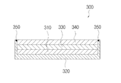
図示されたように、本発明の第2実施例によるリチウム二次電池用負極300は、内部が中空され、一方が開放されるように形成された集電体320を備える。この集電体320の内部に、リチウム金属310、セパレータ330、及び固体電解質340が順に収容されて積層されており、前記集電体320と固体電解質340との接触面に密閉部350が形成されている。
As shown in the drawing, a
この実施例は、上記の本発明の第1実施例と一部類似するが、内部が中空形成され、上側が開放された容器形態の集電体320が形成されており、中空された集電体320の内部に、リチウム金属310、電解質を含有するセパレータ330、及び固体電解質340が順に上側に積層されて、集電体320と固体電解質340との接触面に密閉部350が形成されている。
This embodiment is partly similar to the first embodiment of the present invention described above, but is formed with a hollow collector and a container-shaped
これにより、リチウム金属310が集電体320、固体電解質340、及び密閉部350により密閉されるため、セパレータ330及び固体電解質340を介してリチウムイオンが移動することはできるが、リチウム金属310に水分及び酸素ガスが浸透することを防止することができる。
Accordingly, since the
また、本発明の第2実施例によるリチウム二次電池用負極の製造方法は、内部が中空され、一方が開放されるように形成された集電体320の内部に、リチウム金属310、電解質を含有するセパレータ330、及び固体電解質340を順に積層する段階(SA10)と、前記集電体320の下側及び固体電解質340の上側から、積層方向に加圧する段階(SA20)と、前記集電体320と固体電解質340との接触面に密閉部350を形成する段階(SA30)と、前記密閉部350が形成された後に加圧力を除去する段階(SA40)と、を含む。
In addition, in the method for manufacturing a negative electrode for a lithium secondary battery according to the second embodiment of the present invention, the
即ち、図3(a)のように、リチウム金属310、電解質を含有するセパレータ330、及び固体電解質340を順に積層し、図3(b)のように、積層方向である上下方向に加圧することで接触面が密着されるようにした状態で、集電体320と固体電解質340との接触面を溶接して、溶接部が密閉部350となるように形成した後、図3(c)のように、加圧力を除去して、密着された状態を維持するように結合することができる。これにより、リチウム金属310が密閉されるため、水分が浸透しないように構成されることができ、積層された構成品の接触面が密着されるため、接触抵抗が減少して、性能及び効率が向上されることができる。
That is, as shown in FIG. 3A, the
この際、前記SA30段階で、密閉部350は、半田付け(Soldering)、蝋付け(Brazing)、及びレーザ溶接(Laser Welding)から選択される何れか1つの方法により形成することができる。ここで、集電体320は銅などの金属からなり、固体電解質340はセラミック材質からなるため、レーザ溶接を用いると、図4のように、集電体320の一部のみが溶けて固体電解質340に密着され、溶接部が密閉部350となるように形成されることができる。
At this time, in step SA30, the sealing
また、本発明のリチウム空気電池1000は、前記リチウム二次電池用負極200、300と、一方が空気と接触される気体拡散層411及び前記気体拡散層411の他方に形成された触媒層412を有し、前記リチウム二次電池用負極200、300と離間して形成される正極400と、前記リチウム二次電池用負極200、300と正極400との間に備えられる水系電解質550と、を含む。
In addition, the lithium-
先ず、本発明のリチウム空気電池1000は、大きく、リチウム二次電池用負極200、300と、正極400と、水系電解質550と、で構成される。
First, the lithium-
リチウム二次電池用負極200、300としては、第1実施例によるリチウム二次電池用負極200または第2実施例によるリチウム二次電池用負極300が用いられることができ、以下では、第1実施例によるリチウム二次電池用負極200を用いた場合を例として説明する。
As the
リチウム二次電池用負極200は、上記のように、集電体220、リチウム金属210、電解質を含有するセパレータ230、及び固体電解質240が順に積層されて積層体となり、この積層体の周面に密閉部250が形成されている。この際、リチウム金属210は、リチウムイオンを貯蔵及び放出することができ、バインダーをさらに含むことができる。リチウム金属210としては、例えば、リチウム金属、リチウム金属に基づく合金、またはリチウム挿入化合物(lithium intercalating compound)などが使用でき、水分などに対する耐久性を向上させるためには、リチウム合金を使用することが好ましい。バインダーとしては、例えば、ポリフッ化ビニリデン(PVDF)、ポリテトラフルオロエチレン(PTFE)などが挙げられ、バインダーの含量は、特に限定されないが、例えば、30重量%以下、より具体的には、1〜10重量%であることができる。
As described above, the
正極400は、一方が空気と接触される気体拡散層(Gas Diffusion Layer、GDL)411と、触媒層412と、で構成され、リチウム二次電池用負極200と離間して形成される。この際、正極400は、リチウム二次電池用負極200と対向する面に、触媒層412及び固体電解質240がそれぞれ配置されるように構成される。これにより、空気が気体拡散層411を介して拡散して、触媒層412でリチウムイオンと空気中の酸素との酸化還元反応が起こるように構成される。また、正極400は、活物質として空気中の酸素を用い、酸素及びリチウムイオンが移動できる空隙を有する導電性材料を含有することができる。触媒層412は、白金(Pt)とバインダーとを混合して塗布またはコーティングすることで形成されることができる。即ち、触媒、導電性材料、及びバインダーを混合した後、気体拡散層(若しくはカーボン紙)411上にプレス成形するか、またはアセトン、メチルエチルケトン、N‐メチル‐2‐ピロリドンなどの有機溶剤に、触媒、導電性材料、バインダーを混合して溶解または分散させてスラリーを調整し、これを気体拡散層411上にグラビアコーティング、ブレードコーティング、コンマコーティング、ディップコーティングなどの方法により塗布し、次いで、有機溶剤を揮散させた後、プレスすることで、触媒層412を形成することができる。
The
また、導電性材料としては、例えば、炭素材料、金属繊維などの導電性繊維、銅、銀、ニッケル、アルミニウムなどの金属粉末、ポリフェニレン誘導体などの有機導電性材料が使用できる。炭素材料としては、カーボンブラック、黒鉛、活性炭、カーボンナノチューブ、炭素繊維などが使用でき、芳香族環化合物を含有する合成樹脂、石油ピッチなどを焼成して得られるメソポーラスカーボンが使用できる。 As the conductive material, for example, carbon materials, conductive fibers such as metal fibers, metal powders such as copper, silver, nickel, and aluminum, and organic conductive materials such as polyphenylene derivatives can be used. As the carbon material, carbon black, graphite, activated carbon, carbon nanotube, carbon fiber, and the like can be used, and synthetic resin containing an aromatic ring compound, mesoporous carbon obtained by baking petroleum pitch, and the like can be used.
水系電解質550は、リチウム二次電池用負極200と正極400との間に備えられ、リチウムイオンが移動できるように構成される。
The
これにより、水系電解質550の水分がリチウム二次電池用負極200のリチウム金属210に浸透しないため、リチウム空気電池1000の急激な性能低下が防止され、電池の耐久性が向上される。
As a result, water in the
図5から図7は、本発明の一実施例によるリチウム空気電池を示した分解斜視図、組立斜視図、及びAA´方向の断面図である。 5 to 7 are an exploded perspective view, an assembled perspective view, and a cross-sectional view in the AA ′ direction showing a lithium-air battery according to an embodiment of the present invention.
図示されたように、本発明の一実施例によるリチウム空気電池1000は、上側が開放された空間部111が備えられた第1ハウジング110、及び前記第1ハウジング110の上部に配置されており、前記第1ハウジング110の空間部111を密閉し、且つ下側が開放された空気収容部122及び前記空気収容部122に連通される通気孔121が形成された第2ハウジング120を有するハウジング部100と、前記第1ハウジング110の空間部111に収容される前記リチウム二次電池用負極200と、前記第2ハウジング120の空気収容部122の下側に結合されており、上側に配置された気体拡散層411及び前記気体拡散層411の下側に形成された触媒層412を有し、前記リチウム二次電池用負極200と離間して形成された正極400と、前記第1ハウジング110の空間部111に備えられ、且つ前記リチウム二次電池用負極200と正極400との間に備えられる水系電解質550と、を含む。
As shown in the drawing, a lithium-
先ず、本発明の一実施例によるリチウム空気電池1000は、大きく、ハウジング部100の内部に、リチウム二次電池用負極200、正極400、及び水系電解質550が備えられて構成される。
First, a lithium-
ハウジング部100は、第1ハウジング110と、第2ハウジング120と、を含む。第1ハウジング110は、円板状に形成され、その内部には空間部111が備えられている。この際、空間部111は上側が開放されるように形成される。また、第2ハウジング120は、円板状に形成され、第1ハウジング110の上部に配置されて、第1ハウジング110の空間部111が密閉されるように結合される。この際、第2ハウジング120の下側には空気収容部122が形成されており、空気収容部122と連通する通気孔121が形成されている。この通気孔121を介して、外部の空気が空気収容部122へ/から流入及び排出されることができる。通気孔121は、1つまたは多数個が形成されることができ、空気が空気収容部122へ/から流入及び排出できるように、多様な形態に形成されることができる。
The
また、第2ハウジング120の一方には、第1ハウジング110との結合のための第1固定部127が形成されており、第1固定部127に第1結合部128が挿入されることで、第2ハウジング120と第1ハウジング110とが結合されることができる。この際、第2ハウジング120の第1固定部127は貫通孔の形態で形成され、第1結合部128はボルトの形態で形成される。第1ハウジング110には、第1固定部127に対応する位置に、結合孔112が雌ねじの形態で形成される。第1結合部128が第1固定部127を貫通して結合孔112に結合されることで、第1ハウジング110と第2ハウジング120とが結合されることができる。また、第1ハウジング110と第2ハウジング120とは、ねじ結合の他にも、嵌合、溶接、またはリベット結合などの多様な形態で結合されることができる。
In addition, a
リチウム二次電池用負極200は、集電体220が空間部111の底面に密着され、上側に固体電解質240が配置されるように空間部111に収容される。
The
正極400は、第2ハウジング120の空気収容部122の開放された下側を密閉するように結合される。この際、上側に気体拡散層411が配置され、その下側に触媒層412が配置されるように結合される。これにより、空気収容部122に収容される空気が気体拡散層411を介して拡散して、触媒層412でリチウムイオンと空気中の酸素との酸化還元反応が起こるように構成される。
The
水系電解質550は第1ハウジング110の空間部111に満たされる。即ち、リチウム二次電池用負極200と正極400との間に備えられ、リチウムイオンが移動できるように構成される。
The
これにより、本発明の一実施例によるリチウム空気電池は、負極がコンパクトに構成されるため、リチウム空気電池の構成が簡単となり、負極の電気化学的特性が向上されて、リチウム空気電池の性能が向上される。 Accordingly, in the lithium air battery according to one embodiment of the present invention, since the negative electrode is configured compactly, the configuration of the lithium air battery is simplified, the electrochemical characteristics of the negative electrode are improved, and the performance of the lithium air battery is improved. Be improved.
また、本発明の一実施例によるリチウム空気電池1000は、前記リチウム二次電池用負極200の上側に備えられ、上下を貫通する収容孔531を有する収容体530をさらに含み、前記収容体530は、リチウム二次電池用負極200を空間部111の底面に密着させることができる。
In addition, the lithium-
即ち、収容体530は、図7のように、第2ハウジング120により上側の縁部が加圧される。この収容体530により、リチウム二次電池用負極200が空間部111の底面に密着固定されることができる。この際、収容体530の中央部には、上下を貫通して形成された収容孔531が備えられており、水系電解質550が収容孔531を介して固体電解質240と接触されて、リチウムイオンが移動できるように構成される。
That is, the upper edge of the
これにより、本発明の一実施例によるリチウム空気電池1000は、リチウム二次電池用負極200と第1ハウジング110との接触抵抗が減少し、リチウム空気電池の効率及び性能が向上されることができる。
Accordingly, in the
また、収容体530の上側の縁部に第1密閉部540が介在されて、第1ハウジング110と第2ハウジング120とが結合されることで、リチウム二次電池用負極200が収容体530により空間部111の底面に密着されることができる。この際、第1密閉部540は、Oリング(O‐ring)からなり、リチウム二次電池用負極200を空間部111の底面に密着させ、ハウジング部100の外部に水系電解質550が漏れることを防止することができる。
In addition, the
また、前記ハウジング部100は、前記第1ハウジング110と第2ハウジング120との間に介在され、上下を貫通する固定孔131が形成されており、前記固定孔131に正極400が固定される第3ハウジング130をさらに含む。
In addition, the
即ち、図5〜図7のように、第1ハウジング110と第2ハウジング120との間に第3ハウジング130が介在されて密着される。この際、第1ハウジング110の空間部111にリチウム二次電池用負極200、収容体530、及び第1密閉部540が収容された後、第3ハウジング130が上側から結合されることで、リチウム二次電池用負極200が第1ハウジング110の空間部111の底面に密着されるように結合されることができる。第1ハウジング110と第3ハウジング130とは、ボルトの形態で形成された第2結合部133と、第1ハウジング110に雌ねじ山の形態で形成された結合孔112と、によりねじ結合されることができる。ここで、第3ハウジング130には、第2結合部133が貫通するように、第2固定部132が貫通孔の形態で形成されている。第2固定部132は上側が傾斜するように形成され、第2結合部133は皿ボルトの形態で形成されて、第2結合部133の上側の頭部が第3ハウジング130の上面より上方に突出しないように形成される。これにより、第3ハウジング130の上側に第2ハウジング120が容易に密着結合されることができる。
That is, as shown in FIGS. 5 to 7, the
その後、第3ハウジング130の上側に第2ハウジング120が密着結合される。第3ハウジング130に貫通孔134が形成されており、第1結合部128が第1固定部127及び貫通孔134を貫通して第1ハウジング110の結合孔112にねじ結合されることができる。
Thereafter, the
ここで、第3ハウジング130には固定孔131が形成されており、固定孔131の上側の縁部と第2ハウジング120との間に正極400の縁部が密着されて固定される。この際、固定孔131の上側の縁部は、図示したように、傾斜して形成されていてもよく、または、段差が形成されて、この段差に正極400の縁部が載置されて固定されてもよい。また、固定孔131には水系電解質550が収容されて、リチウム二次電池用負極200と正極400との間にリチウムイオンが移動できるように構成される。
Here, a fixing
これにより、第1ハウジング110、第2ハウジング120、及び第3ハウジング130が堅固に結合されて密着されることができ、リチウム二次電池用負極200の密着力が向上され、正極400の結合及び固定が容易になされる。
As a result, the
また、図8のように、本発明の第2実施例によるリチウム二次電池用負極300を用いて、同一の形態のリチウム空気電池を構成してもよい。
In addition, as shown in FIG. 8, a lithium-air battery of the same form may be configured using the
上記のように、本発明のリチウム二次電池用負極及び製造方法、並びにそれを含むリチウム空気電池は、リチウム空気電池の負極(anode)を構成するリチウム金属に水分及び酸素が浸透することが防止できるため、リチウム空気電池の耐久性が向上され、急激な性能低下を防止することができる。また、負極がコンパクトに構成され、リチウム空気電池の構成が簡単となり、負極の電気化学的特性が向上されて、リチウム空気電池の性能が向上される。 As described above, the negative electrode for a lithium secondary battery and the manufacturing method of the present invention, and the lithium air battery including the same, prevent moisture and oxygen from penetrating into the lithium metal constituting the negative electrode (anode) of the lithium air battery. Therefore, the durability of the lithium-air battery can be improved, and a rapid performance deterioration can be prevented. Further, the negative electrode is compactly configured, the configuration of the lithium air battery is simplified, the electrochemical characteristics of the negative electrode are improved, and the performance of the lithium air battery is improved.
以下は、本発明による二次電池用負極の製造方法の第1実施例及び第2実施例である。 The following are first and second examples of the method for manufacturing a negative electrode for a secondary battery according to the present invention.
[実施例1]接着剤(Adhesive)/密閉剤(Sealant)を用いたLiSICON プロテクティド(protected) Li アノード(Anode)の製造
集電体(CuまたはNi)、リチウム金属(Li foil)、セパレータ、及びLiSICON(OHARA、AG‐1)を、図1(b)のようにプレスを用いて10kg/cm2の圧力を加えて、負極の各構成品が圧着されるようにする。次に、シリコーン接着剤(Loctite 5900、シリコンフランジシーラント(Silicone Flange Sealant)またはスリーエム スーパーシリコン(3M Super Silicone))を、圧着された負極にスパチュラで均一に塗布する。塗布された接着剤が硬化される間(大気中で24時間)に圧力を維持した後、圧力を除去する。この際、負極に形成されたシリコーン密閉部の最終ミクロ組織(microstructure)の変化を誘導するために、圧力、温度、及び維持時間を変化させることができる。
Example 1 Production of LiSICON Protected Li Anode with Adhesive / Sealant Current Collector (Cu or Ni), Lithium Metal (Li foil), Separator, and A pressure of 10 kg / cm 2 is applied to LiSICON (OHARA, AG-1) using a press as shown in FIG. 1B so that each component of the negative electrode is pressure-bonded. Next, a silicone adhesive (Loctite 5900, Silicone Flange Sealant or 3M Super Silicone) is evenly applied to the crimped negative electrode with a spatula. The pressure is removed after maintaining the pressure while the applied adhesive is cured (24 hours in air). At this time, the pressure, temperature, and maintenance time can be changed in order to induce a change in the final microstructure of the silicone sealing part formed on the negative electrode.
[実施例2]レーザ溶接を用いたLiSICON プロテクティド(protected) Li アノード(Anode)の製造
集電体として用いられるCuシートを深絞り(Deep‐drawing)して、缶(can)形状に加工する。リチウム金属(Li foil)、セパレータ、及びLiSICON(OHARA、AG‐1)を、図3(b)のように配置した後、プレスを用いて10kg/cm2の圧力を加えて、各構成品が圧着されるようにする。Laser(IR パルスレーザー(pulsed laser)、1062nm、周波数 1MHz)、スキャナー、オプティクス(Optics)(可変(variable) BET、FL 1000mm オブジェクトレンズ(object lens))で構成されたレーザ溶接機(Laser Welder)を用いて、圧着された負極に溶接を施す。この際、銅(Cu)集電体の融点が1300℃であることを考慮して、レーザの移動速度を1200m/分に維持する。レーザ溶接の場合、瞬間的に凝固されるため、溶接後の維持時間を10分以内にすることができる。この際、溶接部の最終ミクロ組織(microstructure)の変化を誘導するために、プレスの圧力、レーザの出力、レーザビームのスポットサイズ、レーザビームの移動速度、溶接後の維持時間を変化させることができる。
[Example 2] Production of LiSICON protected using laser welding Li anode Anode A Cu sheet used as a current collector is deep-drawn and processed into a can shape. Lithium metal (Li foil), separator, and LiSICON (OHARA, AG-1) were placed as shown in FIG. 3 (b), and a pressure of 10 kg / cm 2 was applied using a press to make each component. Make sure it is crimped. Laser welder (Laser Welder) composed of Laser (IR pulsed laser, 1062 nm, frequency 1 MHz), scanner, Optics (variable BET,
ここで、接着剤や密閉剤、及びゴムを塗布する方法は、負極(anode)を構成する他の構成品に熱的な影響を与えることなく接合がなされるため、熱による損上がないという利点があり、特に、他の機械装置を用いなくても簡単に適用することができる。また、レーザ溶接は、異種材料(例えば、セラミックと金属)を迅速に接合できる。また、用いられるレーザビームのスポットサイズを15μm〜300μmに変化させながらレーザビームの強度を調節することができる。即ち、各構成品の融点、温度変化による形状の変化などを考慮して、溶接公正を多様に設定することができ、溶接時間は10‐6秒以内にすることが、他の構成品への影響を最小化することができる。また、上述の半田付け及び蝋付けなどの接合方法も、異種材料を接合することができ、特に、低温での接合に用いることができる。 Here, the method of applying an adhesive, a sealant, and rubber can be bonded without thermally affecting other components constituting the anode, so there is no loss due to heat. In particular, it can be easily applied without using other mechanical devices. Laser welding can also quickly bond dissimilar materials (eg, ceramic and metal). Further, the intensity of the laser beam can be adjusted while changing the spot size of the laser beam to be used to 15 μm to 300 μm. That is, the melting point of each component, in consideration of the change in shape of due to temperature change, the fair weld can be set variously, welding time be within 10-6 seconds, to other components The impact can be minimized. Also, the above-described joining methods such as soldering and brazing can join different materials, and can be used particularly for joining at low temperatures.
本発明は上記の実施例に限定されず、適用範囲が多様であることが勿論、特許請求の範囲で請求する本発明の要旨を外れることなく、本発明が属する分野において通常の知識を有する者であれば、誰でも多様な変形実施が可能であることはいうまでもない。 The present invention is not limited to the above-described embodiments, and the scope of application is various. Of course, those who have ordinary knowledge in the field to which the present invention belongs without departing from the scope of the present invention claimed in the claims. It goes without saying that anyone can make various modifications.
1000 リチウム空気電池
100 ハウジング部
110 第1ハウジング
111 空間部
112 結合孔
120 第2ハウジング
121 通気孔
122 空気収容部
127 第1固定部
128 第1結合部
130 第3ハウジング
131 固定孔
132 第2固定部
133 第2結合部
134 貫通孔
200、300 リチウム二次電池用負極(anode)
210、310 リチウム金属
220、320 集電体
230、330 セパレータ(有機系電解質)
240、340 固体電解質
250、350 密閉部
400 正極(cathode)
411 気体拡散層
412 触媒層
530 収容体
531 収容孔
540 第1密閉部
550 水系電解質
1000 Lithium-
210, 310
240, 340
411
Claims (13)
前記集電体の上側に積層されるリチウム金属と、
前記リチウム金属の上側に積層され、電解質を含有するセパレータと、
前記セパレータの上側に積層される固体電解質と、
前記集電体、リチウム金属、セパレータ及び固体電解質が積層されてなる積層体の周面を密閉する密閉部と、
を含むリチウム二次電池用負極。 A current collector,
Lithium metal laminated on the upper side of the current collector;
A separator laminated on the upper side of the lithium metal and containing an electrolyte;
A solid electrolyte laminated on top of the separator;
A sealed portion that seals a peripheral surface of a laminate in which the current collector, lithium metal, separator, and solid electrolyte are laminated;
A negative electrode for a lithium secondary battery.
前記積層体を積層方向に加圧する段階と、
前記積層体の周面に密閉部を形成する段階と、
前記密閉部が形成された後に加圧力を除去する段階と、
を含むリチウム二次電池用負極の製造方法。 A step of sequentially stacking a current collector, a lithium metal, a separator containing an electrolyte, and a solid electrolyte to form a laminate;
Pressing the laminate in the laminating direction;
Forming a sealing portion on the peripheral surface of the laminate;
Removing the applied pressure after the sealing portion is formed;
The manufacturing method of the negative electrode for lithium secondary batteries containing.
密閉部は、接着剤(adhesive)、密閉剤(防水剤、sealant)及びゴムから選択される何れか1つを塗布またはコーティングすることで形成される、請求項6に記載のリチウム二次電池用負極の製造方法。 In the step of forming a sealing portion on the peripheral surface of the laminate,
The lithium secondary battery according to claim 6, wherein the sealing portion is formed by applying or coating any one selected from an adhesive, a sealing agent (waterproofing agent, sealant), and rubber. Manufacturing method of negative electrode.
前記集電体の下側及び固体電解質の上側から、積層方向に加圧する段階と、
前記集電体と固体電解質との接触面に密閉部を形成する段階と、
前記密閉部が形成された後に加圧力を除去する段階と、
を含むリチウム二次電池用負極の製造方法。 Laminating lithium metal, an electrolyte-containing separator, and a solid electrolyte in that order inside a current collector that is hollow and one of which is open,
Pressing from the lower side of the current collector and the upper side of the solid electrolyte in the stacking direction;
Forming a sealed portion on a contact surface between the current collector and the solid electrolyte;
Removing the applied pressure after the sealing portion is formed;
The manufacturing method of the negative electrode for lithium secondary batteries containing.
密閉部は、半田付け(soldering)、蝋付け(brazing)、及びレーザ溶接(laser welding)から選択される何れか1つの方法により形成される、請求項8に記載のリチウム二次電池用負極の製造方法。 In the step of forming a sealed portion on the contact surface between the current collector and the solid electrolyte,
The negative electrode for a lithium secondary battery according to claim 8, wherein the sealing part is formed by any one method selected from soldering, brazing, and laser welding. Production method.
一方が空気と接触される気体拡散層及び前記気体拡散層の他方に形成された触媒層を有し、前記リチウム二次電池用負極と離間して形成される正極と、
前記リチウム二次電池用負極と正極との間に備えられる水系電解質と、
を含むリチウム空気電池。 A negative electrode for a lithium secondary battery according to any one of claims 1 to 5,
A positive electrode formed with a gas diffusion layer that is in contact with air and a catalyst layer formed on the other of the gas diffusion layers, and formed separately from the negative electrode for the lithium secondary battery;
An aqueous electrolyte provided between the negative electrode for the lithium secondary battery and the positive electrode;
Including lithium air battery.
前記第1ハウジングの空間部に収容される、請求項1乃至5の何れか一項に記載のリチウム二次電池用負極と、
前記第2ハウジングの空気収容部の下側に結合されており、上側に配置された気体拡散層及び前記気体拡散層の下側に形成された触媒層を有し、前記リチウム二次電池用負極と離間して形成される正極と、
前記第1ハウジングの空間部に備えられ、且つ前記リチウム二次電池用負極と正極との間に備えられる水系電解質と、
を含むリチウム空気電池。 A first housing provided with a space portion whose upper side is open, and an air accommodating portion which is disposed above the first housing, seals the space portion of the first housing, and has a lower side opened; and A housing part having a second housing formed with a vent hole communicating with the air accommodating part;
The negative electrode for a lithium secondary battery according to any one of claims 1 to 5, housed in a space of the first housing,
The negative electrode for a lithium secondary battery, which is coupled to the lower side of the air accommodating part of the second housing, has a gas diffusion layer disposed on the upper side, and a catalyst layer formed on the lower side of the gas diffusion layer. A positive electrode formed apart from,
An aqueous electrolyte provided in a space of the first housing and provided between the negative electrode and the positive electrode for the lithium secondary battery;
Including lithium air battery.
Applications Claiming Priority (2)
| Application Number | Priority Date | Filing Date | Title |
|---|---|---|---|
| KR10-2013-0017951 | 2013-02-20 | ||
| KR1020130017951A KR101561188B1 (en) | 2013-02-20 | 2013-02-20 | Anode for lithium secondary battery, fabricating method thereof and lithium air battery having the same |
Publications (2)
| Publication Number | Publication Date |
|---|---|
| JP2014160656A true JP2014160656A (en) | 2014-09-04 |
| JP6081937B2 JP6081937B2 (en) | 2017-02-15 |
Family
ID=51351418
Family Applications (1)
| Application Number | Title | Priority Date | Filing Date |
|---|---|---|---|
| JP2014030191A Active JP6081937B2 (en) | 2013-02-20 | 2014-02-20 | Negative electrode for lithium secondary battery, method for producing the same, and lithium-air battery including the same |
Country Status (3)
| Country | Link |
|---|---|
| US (2) | US9461302B2 (en) |
| JP (1) | JP6081937B2 (en) |
| KR (1) | KR101561188B1 (en) |
Cited By (3)
| Publication number | Priority date | Publication date | Assignee | Title |
|---|---|---|---|---|
| JPWO2016055908A1 (en) * | 2014-10-10 | 2017-04-27 | 株式会社半導体エネルギー研究所 | Power storage device |
| JP2017537429A (en) * | 2014-10-31 | 2017-12-14 | エルジー・ケム・リミテッド | Secondary battery electrode, manufacturing method thereof, secondary battery including the same, and cable-type secondary battery |
| JP2018517252A (en) * | 2015-05-26 | 2018-06-28 | ユニスト(ウルサン ナショナル インスティテュート オブ サイエンス アンド テクノロジー) | Coin-type secondary battery, method for manufacturing the same, and coin-type secondary battery charge / discharge device |
Families Citing this family (17)
| Publication number | Priority date | Publication date | Assignee | Title |
|---|---|---|---|---|
| US9064805B1 (en) * | 2013-03-13 | 2015-06-23 | Itn Energy Systems, Inc. | Hot-press method |
| WO2016011412A1 (en) | 2014-07-17 | 2016-01-21 | Ada Technologies, Inc. | Extreme long life, high energy density batteries and method of making and using the same |
| KR101675479B1 (en) * | 2014-11-12 | 2016-11-11 | 울산과학기술원 | Manufacturing method for complex catalyst for rechargeable metal-air battery |
| EP3353844B1 (en) | 2015-03-27 | 2022-05-11 | Mason K. Harrup | All-inorganic solvents for electrolytes |
| US10692659B2 (en) | 2015-07-31 | 2020-06-23 | Ada Technologies, Inc. | High energy and power electrochemical device and method of making and using same |
| CN109075413B (en) * | 2016-04-25 | 2021-05-07 | 铃木株式会社 | Negative electrode composite structure of lithium air battery |
| JP6521902B2 (en) * | 2016-06-02 | 2019-05-29 | トヨタ自動車株式会社 | Fluoride ion battery electrolyte and fluoride ion battery |
| US10707531B1 (en) | 2016-09-27 | 2020-07-07 | New Dominion Enterprises Inc. | All-inorganic solvents for electrolytes |
| KR102081772B1 (en) | 2017-03-16 | 2020-02-26 | 주식회사 엘지화학 | Electrode and Lithium Secondary Battery Comprising the Same |
| US11024846B2 (en) | 2017-03-23 | 2021-06-01 | Ada Technologies, Inc. | High energy/power density, long cycle life, safe lithium-ion battery capable of long-term deep discharge/storage near zero volt and method of making and using the same |
| JP7117658B2 (en) * | 2017-05-29 | 2022-08-15 | パナソニックIpマネジメント株式会社 | Lithium metal secondary battery |
| US11133523B2 (en) * | 2017-07-28 | 2021-09-28 | Toyota Motor Engineering & Manufacturing North America, Inc. | Aqueous electrolytes with protonic ionic liquid and batteries using the electrolyte |
| JP6962070B2 (en) * | 2017-08-29 | 2021-11-05 | スズキ株式会社 | Air battery and negative electrode complex used for it |
| JP6939307B2 (en) | 2017-09-19 | 2021-09-22 | トヨタ自動車株式会社 | Method for manufacturing water-based lithium-ion secondary battery, negative electrode active material composite, and method for manufacturing water-based lithium-ion secondary battery |
| US10944096B2 (en) * | 2018-04-10 | 2021-03-09 | GM Global Technology Operations LLC | Method of manufacturing a lithium metal negative electrode |
| KR20200062427A (en) | 2018-11-26 | 2020-06-04 | 주식회사 엘지화학 | Method for preparing lithium secondary battery |
| KR20210156516A (en) * | 2020-06-18 | 2021-12-27 | 주식회사 엘지에너지솔루션 | Sealing apparatus of pouch type secondary battery and manufacturing method for pouch type secondary battery |
Citations (5)
| Publication number | Priority date | Publication date | Assignee | Title |
|---|---|---|---|---|
| JP2005235774A (en) * | 2004-02-20 | 2005-09-02 | Lonnie G Johnson | Lithium oxide battery and manufacturing method therefor |
| JP2009252636A (en) * | 2008-04-09 | 2009-10-29 | Toyota Motor Corp | Air cell |
| WO2011086664A1 (en) * | 2010-01-12 | 2011-07-21 | トヨタ自動車株式会社 | Liquid hydrophobic phase transition substance, and battery comprising same |
| JP2012227119A (en) * | 2011-04-20 | 2012-11-15 | Samsung Electro-Mechanics Co Ltd | Metal air battery and method for manufacturing the same |
| JP5158193B2 (en) * | 2008-12-25 | 2013-03-06 | トヨタ自動車株式会社 | Lithium air battery |
Family Cites Families (12)
| Publication number | Priority date | Publication date | Assignee | Title |
|---|---|---|---|---|
| JP4238645B2 (en) * | 2003-06-12 | 2009-03-18 | 日産自動車株式会社 | Bipolar battery |
| US20080070087A1 (en) * | 2004-02-20 | 2008-03-20 | Excellatron Solid State, Llc | Non-volatile cathodes for lithium oxygen batteries and method of producing same |
| US10566669B2 (en) * | 2004-02-20 | 2020-02-18 | Johnson Ip Holding, Llc | Lithium oxygen batteries having a carbon cloth current collector and method of producing same |
| CN100508701C (en) * | 2004-10-22 | 2009-07-01 | 株式会社村田制作所 | Hybrid multilayer substrate and preparation method thereof |
| US20130084507A1 (en) * | 2005-02-17 | 2013-04-04 | Johnson Ip Holding, Llc | Non-volatile cathodes for lithium oxygen batteries and method of producing same |
| JP5382573B2 (en) * | 2009-02-19 | 2014-01-08 | 国立大学法人三重大学 | Lithium air battery |
| EP2477255B1 (en) * | 2009-09-10 | 2020-02-26 | Envision AESC Energy Devices Ltd. | Stacked battery and method for manufacturing same |
| JP5119277B2 (en) * | 2010-01-12 | 2013-01-16 | 株式会社日立製作所 | ELECTRODE FOR LITHIUM SECONDARY BATTERY AND METHOD FOR PRODUCING THE SAME |
| FR2961637B1 (en) * | 2010-06-16 | 2012-07-27 | Commissariat Energie Atomique | CURRENT COLLECTOR WITH INTEGRATED SEALING MEANS, BIPOLAR BATTERY COMPRISING SUCH A COLLECTOR |
| JP5830953B2 (en) * | 2010-11-17 | 2015-12-09 | ソニー株式会社 | Secondary battery, battery unit and battery module |
| US20120214075A1 (en) * | 2011-02-21 | 2012-08-23 | Excellatron Solid State Llc | Electrochemical cell having air cathode partially infused with carbon dioxide |
| US9564660B2 (en) * | 2013-06-27 | 2017-02-07 | QingHong Technology Co., Ltd. | Electric core for thin film battery |
-
2013
- 2013-02-20 KR KR1020130017951A patent/KR101561188B1/en active IP Right Grant
-
2014
- 2014-02-19 US US14/183,891 patent/US9461302B2/en active Active
- 2014-02-20 JP JP2014030191A patent/JP6081937B2/en active Active
-
2016
- 2016-09-06 US US15/257,167 patent/US9947977B2/en active Active
Patent Citations (5)
| Publication number | Priority date | Publication date | Assignee | Title |
|---|---|---|---|---|
| JP2005235774A (en) * | 2004-02-20 | 2005-09-02 | Lonnie G Johnson | Lithium oxide battery and manufacturing method therefor |
| JP2009252636A (en) * | 2008-04-09 | 2009-10-29 | Toyota Motor Corp | Air cell |
| JP5158193B2 (en) * | 2008-12-25 | 2013-03-06 | トヨタ自動車株式会社 | Lithium air battery |
| WO2011086664A1 (en) * | 2010-01-12 | 2011-07-21 | トヨタ自動車株式会社 | Liquid hydrophobic phase transition substance, and battery comprising same |
| JP2012227119A (en) * | 2011-04-20 | 2012-11-15 | Samsung Electro-Mechanics Co Ltd | Metal air battery and method for manufacturing the same |
Cited By (5)
| Publication number | Priority date | Publication date | Assignee | Title |
|---|---|---|---|---|
| JPWO2016055908A1 (en) * | 2014-10-10 | 2017-04-27 | 株式会社半導体エネルギー研究所 | Power storage device |
| US10497979B2 (en) | 2014-10-10 | 2019-12-03 | Semiconductor Energy Laboratory Co., Ltd. | Power storage device and electronic device |
| JP2017537429A (en) * | 2014-10-31 | 2017-12-14 | エルジー・ケム・リミテッド | Secondary battery electrode, manufacturing method thereof, secondary battery including the same, and cable-type secondary battery |
| US10826129B2 (en) | 2014-10-31 | 2020-11-03 | Lg Chem, Ltd. | Electrode for secondary battery, method for manufacturing same, secondary battery comprising same, and cable-type secondary battery |
| JP2018517252A (en) * | 2015-05-26 | 2018-06-28 | ユニスト(ウルサン ナショナル インスティテュート オブ サイエンス アンド テクノロジー) | Coin-type secondary battery, method for manufacturing the same, and coin-type secondary battery charge / discharge device |
Also Published As
| Publication number | Publication date |
|---|---|
| US9947977B2 (en) | 2018-04-17 |
| US9461302B2 (en) | 2016-10-04 |
| KR101561188B1 (en) | 2015-10-16 |
| JP6081937B2 (en) | 2017-02-15 |
| US20140234732A1 (en) | 2014-08-21 |
| KR20140104152A (en) | 2014-08-28 |
| US20160380320A1 (en) | 2016-12-29 |
Similar Documents
| Publication | Publication Date | Title |
|---|---|---|
| JP6081937B2 (en) | Negative electrode for lithium secondary battery, method for producing the same, and lithium-air battery including the same | |
| US9960450B2 (en) | Non-aqueous electrolyte solution for secondary batteries, and lithium ion secondary battery | |
| JP5157107B2 (en) | Non-aqueous electrolyte battery | |
| JP5201847B2 (en) | Nonaqueous electrolyte secondary battery | |
| WO2011161822A1 (en) | Air cell | |
| KR102126278B1 (en) | Lithium air battery | |
| JP2005229103A (en) | Nonaqueous electrolyte for electrochemical element, and electric double-layer capacitor or secondary cell containing the same | |
| KR101306410B1 (en) | Hermetically sealed battery and method for manufacturing the same | |
| WO2015049957A1 (en) | Sealed electric storage device and method for manufacturing same | |
| JP5115109B2 (en) | Non-aqueous electrolyte battery | |
| US20160126595A1 (en) | Molten salt battery | |
| JP2018181622A (en) | Multilayer type secondary battery | |
| JP6592380B2 (en) | Electrolyte for sodium ion secondary battery and sodium ion secondary battery | |
| KR20150128683A (en) | Positive electrode active material for sodium molten salt batteries, positive electrode for sodium molten salt batteries, and sodium molten salt battery | |
| KR101581349B1 (en) | Lithium air battery | |
| US9997813B2 (en) | Lithium air battery | |
| JP5792846B2 (en) | Lithium air battery | |
| JP2013114792A (en) | Safety valve, and molten salt electrolyte battery equipped with safety valve and manufacturing method thereof | |
| JP2017021986A (en) | Nonaqueous secondary battery | |
| JP6042992B2 (en) | Lithium air battery | |
| JP5092347B2 (en) | Nonaqueous electrolyte secondary battery | |
| FR3012260A1 (en) | ELECTROCHEMICAL CELL FOR LITHIUM ACCUMULATOR AND LITHIUM ACCUMULATOR COMPRISING SUCH AN ELECTROCHEMICAL CELL | |
| JP2016038946A (en) | Molten salt battery and method for manufacturing the same | |
| WO2019111691A1 (en) | Secondary battery | |
| JP2019083095A (en) | Positive electrode mixture layer, positive electrode, semi secondary battery, and secondary battery |
Legal Events
| Date | Code | Title | Description |
|---|---|---|---|
| A977 | Report on retrieval |
Free format text: JAPANESE INTERMEDIATE CODE: A971007 Effective date: 20141219 |
|
| A131 | Notification of reasons for refusal |
Free format text: JAPANESE INTERMEDIATE CODE: A131 Effective date: 20150107 |
|
| A521 | Request for written amendment filed |
Free format text: JAPANESE INTERMEDIATE CODE: A523 Effective date: 20150403 |
|
| A131 | Notification of reasons for refusal |
Free format text: JAPANESE INTERMEDIATE CODE: A131 Effective date: 20150902 |
|
| A601 | Written request for extension of time |
Free format text: JAPANESE INTERMEDIATE CODE: A601 Effective date: 20151127 |
|
| A601 | Written request for extension of time |
Free format text: JAPANESE INTERMEDIATE CODE: A601 Effective date: 20151224 |
|
| A521 | Request for written amendment filed |
Free format text: JAPANESE INTERMEDIATE CODE: A523 Effective date: 20160119 |
|
| A131 | Notification of reasons for refusal |
Free format text: JAPANESE INTERMEDIATE CODE: A131 Effective date: 20160316 |
|
| A601 | Written request for extension of time |
Free format text: JAPANESE INTERMEDIATE CODE: A601 Effective date: 20160615 |
|
| RD13 | Notification of appointment of power of sub attorney |
Free format text: JAPANESE INTERMEDIATE CODE: A7433 Effective date: 20160624 |
|
| A521 | Request for written amendment filed |
Free format text: JAPANESE INTERMEDIATE CODE: A821 Effective date: 20160624 |
|
| A521 | Request for written amendment filed |
Free format text: JAPANESE INTERMEDIATE CODE: A523 Effective date: 20160815 |
|
| A521 | Request for written amendment filed |
Free format text: JAPANESE INTERMEDIATE CODE: A523 Effective date: 20160809 |
|
| A131 | Notification of reasons for refusal |
Free format text: JAPANESE INTERMEDIATE CODE: A131 Effective date: 20160928 |
|
| A521 | Request for written amendment filed |
Free format text: JAPANESE INTERMEDIATE CODE: A523 Effective date: 20161104 |
|
| TRDD | Decision of grant or rejection written | ||
| A01 | Written decision to grant a patent or to grant a registration (utility model) |
Free format text: JAPANESE INTERMEDIATE CODE: A01 Effective date: 20161221 |
|
| A61 | First payment of annual fees (during grant procedure) |
Free format text: JAPANESE INTERMEDIATE CODE: A61 Effective date: 20170119 |
|
| R150 | Certificate of patent or registration of utility model |
Ref document number: 6081937 Country of ref document: JP Free format text: JAPANESE INTERMEDIATE CODE: R150 |
|
| R250 | Receipt of annual fees |
Free format text: JAPANESE INTERMEDIATE CODE: R250 |
|
| R250 | Receipt of annual fees |
Free format text: JAPANESE INTERMEDIATE CODE: R250 |
|
| R250 | Receipt of annual fees |
Free format text: JAPANESE INTERMEDIATE CODE: R250 |
|
| R250 | Receipt of annual fees |
Free format text: JAPANESE INTERMEDIATE CODE: R250 |
|
| R250 | Receipt of annual fees |
Free format text: JAPANESE INTERMEDIATE CODE: R250 |