JP2014153360A - Optical encoder - Google Patents
Optical encoder Download PDFInfo
- Publication number
- JP2014153360A JP2014153360A JP2014019238A JP2014019238A JP2014153360A JP 2014153360 A JP2014153360 A JP 2014153360A JP 2014019238 A JP2014019238 A JP 2014019238A JP 2014019238 A JP2014019238 A JP 2014019238A JP 2014153360 A JP2014153360 A JP 2014153360A
- Authority
- JP
- Japan
- Prior art keywords
- scanning
- optical fiber
- transmission grating
- linear scale
- partial beam
- Prior art date
- Legal status (The legal status is an assumption and is not a legal conclusion. Google has not performed a legal analysis and makes no representation as to the accuracy of the status listed.)
- Granted
Links
- 230000003287 optical effect Effects 0.000 title claims abstract description 63
- 239000013307 optical fiber Substances 0.000 claims abstract description 111
- 230000036961 partial effect Effects 0.000 claims abstract description 86
- 238000005259 measurement Methods 0.000 claims abstract description 25
- 230000005540 biological transmission Effects 0.000 claims description 120
- 238000001514 detection method Methods 0.000 claims description 28
- 230000008859 change Effects 0.000 claims description 13
- 230000000694 effects Effects 0.000 claims description 7
- 239000000758 substrate Substances 0.000 claims description 5
- 230000009471 action Effects 0.000 claims description 3
- 230000000737 periodic effect Effects 0.000 claims description 3
- 230000005855 radiation Effects 0.000 claims description 2
- 238000012546 transfer Methods 0.000 claims description 2
- 230000004907 flux Effects 0.000 abstract 5
- 230000004304 visual acuity Effects 0.000 abstract 1
- 239000013598 vector Substances 0.000 description 23
- 238000001228 spectrum Methods 0.000 description 15
- 230000008878 coupling Effects 0.000 description 8
- 238000010168 coupling process Methods 0.000 description 8
- 238000005859 coupling reaction Methods 0.000 description 8
- 230000003595 spectral effect Effects 0.000 description 7
- 230000010363 phase shift Effects 0.000 description 6
- 230000008901 benefit Effects 0.000 description 4
- 239000006185 dispersion Substances 0.000 description 4
- 239000000463 material Substances 0.000 description 4
- BJQHLKABXJIVAM-UHFFFAOYSA-N bis(2-ethylhexyl) phthalate Chemical compound CCCCC(CC)COC(=O)C1=CC=CC=C1C(=O)OCC(CC)CCCC BJQHLKABXJIVAM-UHFFFAOYSA-N 0.000 description 3
- 230000010287 polarization Effects 0.000 description 3
- 238000012545 processing Methods 0.000 description 3
- 230000001902 propagating effect Effects 0.000 description 3
- 230000002829 reductive effect Effects 0.000 description 3
- 230000002411 adverse Effects 0.000 description 2
- 239000000835 fiber Substances 0.000 description 2
- 238000005286 illumination Methods 0.000 description 2
- 238000000034 method Methods 0.000 description 2
- 229910021532 Calcite Inorganic materials 0.000 description 1
- GYHNNYVSQQEPJS-UHFFFAOYSA-N Gallium Chemical compound [Ga] GYHNNYVSQQEPJS-UHFFFAOYSA-N 0.000 description 1
- BQCADISMDOOEFD-UHFFFAOYSA-N Silver Chemical compound [Ag] BQCADISMDOOEFD-UHFFFAOYSA-N 0.000 description 1
- 239000006117 anti-reflective coating Substances 0.000 description 1
- 230000009286 beneficial effect Effects 0.000 description 1
- 239000011248 coating agent Substances 0.000 description 1
- 238000000576 coating method Methods 0.000 description 1
- 239000000470 constituent Substances 0.000 description 1
- 230000007423 decrease Effects 0.000 description 1
- 230000001419 dependent effect Effects 0.000 description 1
- 230000005672 electromagnetic field Effects 0.000 description 1
- 238000000295 emission spectrum Methods 0.000 description 1
- 238000011156 evaluation Methods 0.000 description 1
- 229910052733 gallium Inorganic materials 0.000 description 1
- 239000011521 glass Substances 0.000 description 1
- 230000012447 hatching Effects 0.000 description 1
- 230000002452 interceptive effect Effects 0.000 description 1
- 238000004519 manufacturing process Methods 0.000 description 1
- 238000005498 polishing Methods 0.000 description 1
- 230000000644 propagated effect Effects 0.000 description 1
- 238000013139 quantization Methods 0.000 description 1
- 239000010453 quartz Substances 0.000 description 1
- 230000009467 reduction Effects 0.000 description 1
- 230000002441 reversible effect Effects 0.000 description 1
- 229940082569 selenite Drugs 0.000 description 1
- MCAHWIHFGHIESP-UHFFFAOYSA-L selenite(2-) Chemical compound [O-][Se]([O-])=O MCAHWIHFGHIESP-UHFFFAOYSA-L 0.000 description 1
- VYPSYNLAJGMNEJ-UHFFFAOYSA-N silicon dioxide Inorganic materials O=[Si]=O VYPSYNLAJGMNEJ-UHFFFAOYSA-N 0.000 description 1
- 229910052709 silver Inorganic materials 0.000 description 1
- 239000004332 silver Substances 0.000 description 1
Images


Classifications
-
- G—PHYSICS
- G01—MEASURING; TESTING
- G01B—MEASURING LENGTH, THICKNESS OR SIMILAR LINEAR DIMENSIONS; MEASURING ANGLES; MEASURING AREAS; MEASURING IRREGULARITIES OF SURFACES OR CONTOURS
- G01B11/00—Measuring arrangements characterised by the use of optical techniques
- G01B11/14—Measuring arrangements characterised by the use of optical techniques for measuring distance or clearance between spaced objects or spaced apertures
-
- G—PHYSICS
- G01—MEASURING; TESTING
- G01D—MEASURING NOT SPECIALLY ADAPTED FOR A SPECIFIC VARIABLE; ARRANGEMENTS FOR MEASURING TWO OR MORE VARIABLES NOT COVERED IN A SINGLE OTHER SUBCLASS; TARIFF METERING APPARATUS; MEASURING OR TESTING NOT OTHERWISE PROVIDED FOR
- G01D5/00—Mechanical means for transferring the output of a sensing member; Means for converting the output of a sensing member to another variable where the form or nature of the sensing member does not constrain the means for converting; Transducers not specially adapted for a specific variable
- G01D5/26—Mechanical means for transferring the output of a sensing member; Means for converting the output of a sensing member to another variable where the form or nature of the sensing member does not constrain the means for converting; Transducers not specially adapted for a specific variable characterised by optical transfer means, i.e. using infrared, visible, or ultraviolet light
- G01D5/266—Mechanical means for transferring the output of a sensing member; Means for converting the output of a sensing member to another variable where the form or nature of the sensing member does not constrain the means for converting; Transducers not specially adapted for a specific variable characterised by optical transfer means, i.e. using infrared, visible, or ultraviolet light by interferometric means
-
- G—PHYSICS
- G01—MEASURING; TESTING
- G01D—MEASURING NOT SPECIALLY ADAPTED FOR A SPECIFIC VARIABLE; ARRANGEMENTS FOR MEASURING TWO OR MORE VARIABLES NOT COVERED IN A SINGLE OTHER SUBCLASS; TARIFF METERING APPARATUS; MEASURING OR TESTING NOT OTHERWISE PROVIDED FOR
- G01D5/00—Mechanical means for transferring the output of a sensing member; Means for converting the output of a sensing member to another variable where the form or nature of the sensing member does not constrain the means for converting; Transducers not specially adapted for a specific variable
- G01D5/26—Mechanical means for transferring the output of a sensing member; Means for converting the output of a sensing member to another variable where the form or nature of the sensing member does not constrain the means for converting; Transducers not specially adapted for a specific variable characterised by optical transfer means, i.e. using infrared, visible, or ultraviolet light
- G01D5/268—Mechanical means for transferring the output of a sensing member; Means for converting the output of a sensing member to another variable where the form or nature of the sensing member does not constrain the means for converting; Transducers not specially adapted for a specific variable characterised by optical transfer means, i.e. using infrared, visible, or ultraviolet light using optical fibres
-
- G—PHYSICS
- G01—MEASURING; TESTING
- G01D—MEASURING NOT SPECIALLY ADAPTED FOR A SPECIFIC VARIABLE; ARRANGEMENTS FOR MEASURING TWO OR MORE VARIABLES NOT COVERED IN A SINGLE OTHER SUBCLASS; TARIFF METERING APPARATUS; MEASURING OR TESTING NOT OTHERWISE PROVIDED FOR
- G01D5/00—Mechanical means for transferring the output of a sensing member; Means for converting the output of a sensing member to another variable where the form or nature of the sensing member does not constrain the means for converting; Transducers not specially adapted for a specific variable
- G01D5/26—Mechanical means for transferring the output of a sensing member; Means for converting the output of a sensing member to another variable where the form or nature of the sensing member does not constrain the means for converting; Transducers not specially adapted for a specific variable characterised by optical transfer means, i.e. using infrared, visible, or ultraviolet light
- G01D5/32—Mechanical means for transferring the output of a sensing member; Means for converting the output of a sensing member to another variable where the form or nature of the sensing member does not constrain the means for converting; Transducers not specially adapted for a specific variable characterised by optical transfer means, i.e. using infrared, visible, or ultraviolet light with attenuation or whole or partial obturation of beams of light
- G01D5/34—Mechanical means for transferring the output of a sensing member; Means for converting the output of a sensing member to another variable where the form or nature of the sensing member does not constrain the means for converting; Transducers not specially adapted for a specific variable characterised by optical transfer means, i.e. using infrared, visible, or ultraviolet light with attenuation or whole or partial obturation of beams of light the beams of light being detected by photocells
- G01D5/36—Forming the light into pulses
- G01D5/38—Forming the light into pulses by diffraction gratings
Abstract
Description
本発明は、請求項1に記載の上位概念による光学式エンコーダに関する。
The present invention relates to an optical encoder according to the superordinate concept of
公知の光学式エンコーダは、リニアスケール及びこのリニアスケールに対して可動な走査装置を有する。一般に、光源、光電検出素子及びレンズ、格子等の光学素子が、この走査装置内に配置されている。しかしながら、特定の使用状況に対しては、これらの全ての素子を有する走査装置が、場合によっては非常に大きく構成されうる。さらに、妨害電磁場又は高温に起因した当該走査装置の能動部品の望まない影響が、特定の用途で発生しうる。さらに、光源の電力損失に起因した熱が、測定精度に影響しうる。 A known optical encoder has a linear scale and a scanning device movable with respect to the linear scale. In general, optical elements such as a light source, a photoelectric detection element, a lens, and a grating are arranged in the scanning device. However, for certain usage situations, a scanning device having all these elements can be configured very large in some cases. Furthermore, unwanted effects of the active components of the scanning device due to disturbing electromagnetic fields or high temperatures can occur in certain applications. Furthermore, heat due to power loss of the light source can affect the measurement accuracy.
それ故に、走査されるリニアスケール及びこのリニアスケールに対して可動な受動的な光ファイバ走査ヘッドだけが、実際の測定地点に配置される光学式エンコーダのための解決手段が公知である。光源及び光電検出素子のような、走査機能に関連するその他の能動部品は、当該測定地点から空間的に離れて配置され、且つ光ファイバを通じて光ファイバ走査ヘッドに接続されている。こうして、非常にコンパクトに構成される装置が、実際の測定地点で構成され得る。さらに、走査側の、各種能動部品に対する悪影響も減少され得る。 Therefore, solutions are known for optical encoders in which only the linear scale to be scanned and the passive optical fiber scanning head movable relative to this linear scale are located at the actual measurement point. Other active components related to the scanning function, such as the light source and the photoelectric detection element, are disposed spatially away from the measurement point and connected to the optical fiber scanning head through the optical fiber. In this way, a very compact device can be constructed with actual measurement points. In addition, the adverse effects on the various active components on the scanning side can be reduced.
上記エンコーダは、例えば、本出願人の独国特許出願公開第102007024349号明細書で提唱されてある。この明細書に開示されたエンコーダは、反射型リニアスールとして形成されたリニアスケールのほかに、このリニアスケールに対して少なくとも1つの測定方向に移動可能な光ファイバ走査ヘッドを有する。当該エンコーダのその他の部品が、適切な光ファイバを経由して、この光ファイバ走査ヘッドの後方に空間的に離れて配置されている。例えば、光学式の走査に必要な光源、複数の光電検出素子及び場合によっては、信号を生成して信号をさらに処理するためのその他の能動部品が、これらの部品に属する。さらに、当該完全に受動的な光ファイバ走査ヘッドは、走査板と、信号を生成する照射ビーム束を供給して帰還させるための光ファイバの端部とを有する。複数の位相差走査信号を生成するため、当該走査信号を波長に応じてコード化することが提唱されている。このため、当該走査板は広帯域で照射され、且つ、この走査板は、複数の単位格子から構成される。これらの単位格子はそれぞれ、複数の領域から構成される。これらの領域は、照射スペクトルの幾つかの波長領域に対して透過性である。このため、当該走査板の単位格子ごとの当該異なる領域が、例えば、異なる波長を透過させる部分エタロンとして形成されている。しかしながら、当該独国特許出願公開第102007024349号明細書で利用される走査原理は、反射型リニア格子側の、非常に小さい目盛周期に対しては使用され得ない。何故なら、部分エタロンの波長に関係する透過性を維持しつつ、当該部分エタロンを任意に小さくすることができないからである。 Such an encoder is proposed, for example, in DE 102007024349 of the present applicant. The encoder disclosed in this specification has, in addition to a linear scale formed as a reflective linear scale, an optical fiber scanning head that can move in at least one measurement direction with respect to the linear scale. The other parts of the encoder are arranged spatially separated behind this optical fiber scanning head via a suitable optical fiber. For example, these components include the light source required for optical scanning, a plurality of photoelectric detection elements, and possibly other active components for generating signals and further processing the signals. Further, the fully passive optical fiber scanning head has a scanning plate and an end of an optical fiber for supplying and returning an irradiation beam bundle that generates a signal. In order to generate a plurality of phase difference scanning signals, it has been proposed to code the scanning signals according to wavelength. Therefore, the scanning plate is irradiated with a wide band, and the scanning plate is composed of a plurality of unit lattices. Each of these unit cells is composed of a plurality of regions. These regions are transparent to several wavelength regions of the illumination spectrum. For this reason, the different region for each unit lattice of the scanning plate is formed as a partial etalon that transmits different wavelengths, for example. However, the scanning principle used in the DE-A-102007024349 cannot be used for very small scale periods on the reflective linear grating side. This is because the partial etalon cannot be arbitrarily reduced while maintaining the transparency related to the wavelength of the partial etalon.
本発明の課題は、高い分解能の位置測定が可能である受動的な光ファイバ走査ヘッドを有する光学式エンコーダを提供することにある。 An object of the present invention is to provide an optical encoder having a passive optical fiber scanning head capable of high-resolution position measurement.
この課題は、請求項1に記載の特徴を有する光学式エンコーダによって解決される。
This problem is solved by an optical encoder having the features of
本発明の光学式エンコーダの好適な構成は、従属請求項に記載されている。 Preferred configurations of the optical encoder according to the invention are described in the dependent claims.
本発明の光学式エンコーダは、光ファイバ走査ヘッドと、この光ファイバ走査ヘッドに対して少なくとも1つの測定方向に可動な反射型リニアスケールとの相対位置に関する複数の位相差走査信号を生成するために使用される。当該光ファイバ走査ヘッド内では、走査板が、光ファイバの、リニアスケール側の端部の前方に配置されている。位相差走査信号が、波長に応じてコード化される。
・走査板上に入射した1つのビーム束が、少なくとも2つの部分ビーム束に分割され、これらの部分ビーム束が、反射型リニアスケールに照射され、次いで位相差走査信号を生成するために再集束して互いに干渉し、
・これらの部分ビーム束が、当該分割と当該再集束との間に異なる光路長を進行するように、当該走査板は形成されている。
The optical encoder of the present invention generates a plurality of phase difference scanning signals relating to the relative position of an optical fiber scanning head and a reflective linear scale movable in at least one measurement direction relative to the optical fiber scanning head. used. In the optical fiber scanning head, the scanning plate is disposed in front of the end portion of the optical fiber on the linear scale side. The phase difference scanning signal is encoded according to the wavelength.
One beam bundle incident on the scan plate is split into at least two partial beam bundles, which are irradiated onto a reflective linear scale and then refocused to generate a phase difference scan signal Interfere with each other,
The scanning plate is formed so that these partial beam bundles travel different optical path lengths between the splitting and the refocusing.
好適な実施の形態では、さらに、少なくとも2つの部分ビーム束が、走査板と反射型リニアスケールとの間でこの走査板の法線に対して対称に伝播し、これらの部分ビーム束のリトロー角度を成してこの反射型リニアスケールに照射されるように、当該走査板は形成されている。 In a preferred embodiment, furthermore, at least two partial beam bundles propagate symmetrically with respect to the normal of the scanning plate between the scanning plate and the reflective linear scale, the Littrow angles of these partial beam bundles. The scanning plate is formed to irradiate the reflective linear scale.
特に、使用される反射型リニアスケールは、±1次の回折次数で最大回折効率を有する。 In particular, the reflective linear scale used has a maximum diffraction efficiency at the first order diffraction orders.
光ファイバが、マルチモード光ファイバとして形成されていて、光ファイバ走査ヘッドに向けて照射するために使用されるビーム束と、この光ファイバ走査ヘッドから離れるように再集束する部分ビーム束との双方が、当該光ファイバを通じて伝送可能であることが提唱され得る。 Both the beam bundle, wherein the optical fiber is formed as a multimode optical fiber and used to irradiate the optical fiber scan head, and the partial beam bundle that refocuses away from the optical fiber scan head Can be proposed to be transmitted through the optical fiber.
さらに、光ファイバの、リニアスケールに面しない端部に、
・スペクトル広帯域の1つの光源、又は、
・異なる波長の放射光を放射する複数の光源
が配置されていることが可能である。当該光源の放射光が、照射ビーム束としてカップリング手段を通じて光ファイバ内に入射可能である。
Furthermore, at the end of the optical fiber that does not face the linear scale,
One light source with a broad spectrum, or
It is possible to arrange a plurality of light sources that emit radiation of different wavelengths. The light emitted from the light source can enter the optical fiber through the coupling means as an irradiation beam bundle.
この場合、検出装置が、光ファイバの、リニアスケールに面しない端部に配置され得る。当該検出装置は、
・再集束した部分ビーム束を波長に応じて分光するための分光手段、及び
・複数の光電検出素子を有する。これらの光電検出素子は、当該分光された部分ビーム束を転送可能であり、且つ当該検出された部分ビーム束を電気的な位相差走査信号に変換する。
In this case, the detection device can be arranged at the end of the optical fiber that does not face the linear scale. The detection device is
A spectroscopic means for splitting the refocused partial beam bundle according to the wavelength, and a plurality of photoelectric detection elements. These photoelectric detection elements can transfer the split partial beam bundle, and convert the detected partial beam bundle into an electrical phase difference scanning signal.
好ましくは、当該走査板は、板状で透過性の基板として形成されている。この場合
・第1透過格子が、走査板の、光ファイバに面した面上に配置されている。この第1透過格子は、この第1透過格子上に入射するビーム束を少なくとも2つの回折部分ビーム束に分割する。これらの回折部分ビーム束は、走査板の法線に対して非対称に引き続き伝播する。
・第2透過格子が、走査板の、反射型リニアスケールに面した面上に配置されている。第1透過格子からこの第2透過格子上に入射する複数の部分ビーム束が、走査板の法線に対して互いに対称にこの走査板とこの反射型リニアスケールとの間を伝播し、これらの部分ビーム束のリトロー角度を成してこの反射型リニアスケールに照射されるように、この第2透過格子は、当該複数の部分ビーム束を回折させる。
Preferably, the scanning plate is formed as a plate-like and transmissive substrate. In this case, the first transmission grating is arranged on the surface of the scanning plate facing the optical fiber. The first transmission grating divides the beam bundle incident on the first transmission grating into at least two diffractive partial beam bundles. These diffractive partial beam bundles continue to propagate asymmetrically with respect to the normal of the scan plate.
The second transmission grating is arranged on the surface of the scanning plate facing the reflective linear scale. A plurality of partial beam bundles incident on the second transmission grating from the first transmission grating propagate between the scanning plate and the reflective linear scale symmetrically to each other with respect to the normal line of the scanning plate. The second transmission grating diffracts the plurality of partial beam bundles so that the reflective linear scale is irradiated with a Littrow angle of the partial beam bundle.
有利には、第1透過格子及び第2透過格子がそれぞれ、ブレーズド位相格子として形成されている。 Advantageously, the first transmission grating and the second transmission grating are each formed as a blazed phase grating.
第1透過格子と第2透過格子とが、測定方向に沿って周期的な位相変化を有することが提唱され得る。 It can be proposed that the first transmission grating and the second transmission grating have a periodic phase change along the measurement direction.
さらに、第1透過格子上に入射する部分ビームにコリメート作用をこの第1透過格子を通じて及ぼすように、この第1透過格子を形成することが可能である。 Furthermore, it is possible to form the first transmission grating so as to exert a collimating action on the partial beam incident on the first transmission grating through the first transmission grating.
特に、位相差走査信号に寄与する複数の信号成分の多重走査を設定するため、走査板の厚さ及び/又はこの走査板上に配置された両透過格子の格子パラメータが適切に選択されている。 In particular, in order to set multiple scanning of a plurality of signal components that contribute to the phase difference scanning signal, the thickness of the scanning plate and / or the grating parameters of both transmission gratings arranged on the scanning plate are appropriately selected. .
別の実施の形態では、直線偏光された1つのビーム束が、走査板上に入射することが提唱され得る。この場合、
・第1透過格子が、走査板の、光ファイバに面した面上に配置されている。この第1透過格子は、この第1透過格子上に入射するビーム束を少なくとも2つの回折部分ビーム束に分割する。
・複屈折要素が、走査板の、反射型リニアスケールに面した面上に配置されている。この複屈折要素内では、当該分割された複数の部分ビーム束が、走査板の法線に対して非対称に引き続き伝播し、この走査板を離れた後に、この走査板の法線に対して互いに対称に、この走査板とこの反射型リニアスケールとの間を伝播し、これらの部分ビーム束のリトロー角度を成してこの反射型リニアスケールに照射される。
In another embodiment, it may be proposed that a linearly polarized beam bundle is incident on the scan plate. in this case,
The first transmission grating is arranged on the surface of the scanning plate facing the optical fiber. The first transmission grating divides the beam bundle incident on the first transmission grating into at least two diffractive partial beam bundles.
A birefringent element is arranged on the surface of the scanning plate facing the reflective linear scale. Within this birefringent element, the split partial beam bundles continue to propagate asymmetrically with respect to the normal of the scan plate and after leaving the scan plate, with respect to the normal of the scan plate. Symmetrically, it propagates between the scanning plate and the reflective linear scale and irradiates the reflective linear scale at a Littrow angle of these partial beam bundles.
有益には、位相差走査信号に寄与する複数の信号成分の多重走査を設定するため、複屈折要素の厚さが適切に選択されている。 Beneficially, the thickness of the birefringent element is appropriately selected to set up multiple scans of multiple signal components that contribute to the phase difference scan signal.
さらに、分光手段が、ビーム路内に連続して配置された複数の回折格子を有することが提唱され得る。 Furthermore, it can be proposed that the spectroscopic means comprises a plurality of diffraction gratings arranged in succession in the beam path.
さらに、反射防止膜が、光ファイバの、リニアスケールに面しない端部に配置されていること、及び/又は、光ファイバの当該端部が、斜め研磨されていることが可能である。 Furthermore, the antireflection film can be disposed at the end of the optical fiber that does not face the linear scale, and / or the end of the optical fiber can be obliquely polished.
本発明の光学式エンコーダによれば、高い分解能の位置測定も、受動的な光ファイバ走査ヘッドによって実施できる。すなわち、非常に小さい目盛周期を有する反射型リニアスケールが、当該光ファイバ走査ヘッドを用いて走査され得る。 According to the optical encoder of the present invention, high-resolution position measurement can also be performed by a passive optical fiber scanning head. That is, a reflective linear scale having a very small graduation period can be scanned using the optical fiber scanning head.
その他の利点としては、分割された複数の部分ビーム束が、光ファイバ走査ヘッドと反射型リニアスケールとの間で対称に進行するので、本発明の装置は、当該走査間隔の変動に対して非常に鈍感である。つまり、特に、計測される位置が、当該走査間隔から影響を受けないことが指摘され得る。 Another advantage is that since the split partial beam bundles travel symmetrically between the fiber optic scan head and the reflective linear scale, the device of the present invention is extremely sensitive to variations in the scan interval. Insensitive to. That is, in particular, it can be pointed out that the position to be measured is not affected by the scanning interval.
さらに、本発明の光学式エンコーダの受動的な光ファイバ走査ヘッドは、非常に簡単な構造を成し、且つ非常にコンパクトに構成される。 Furthermore, the passive optical fiber scanning head of the optical encoder of the present invention has a very simple structure and is very compact.
以下に、本発明のさらなる詳細及び利点を図面に示された本発明のエンコーダの実施の形態に基づいて説明する。 In the following, further details and advantages of the present invention will be described based on embodiments of the encoder of the present invention shown in the drawings.
以下に、本発明のエンコーダの第1の実施の形態を図1、2a及び2bに基づいて説明する。 Below, the 1st Embodiment of the encoder of this invention is described based on FIG. 1, 2a and 2b.
図示された実施の形態の光学式エンコーダは、反射型リニアスケール10を有する。この反射型リニアスケール10は、光ファイバ走査ヘッド20に対して相対移動可能に、示された測定方向xに配置されている。この場合、反射型リニアスケール10が固定式に配置され且つ光ファイバ走査ヘッド20が移動式に配置され得る、又は、反射型リニアスケール10が移動式に配置され且つ光ファイバ走査ヘッド20が固定式に配置され得る。反射型リニアスケール10及び光ファイバ走査ヘッド20は、−図示されなかった−2つの物体に結合されている。これらの物体は、測定方向xに互いに相対移動可能であり、これらの物体の向き合った相対位置が測定され得る。この場合、これらの物体は、例えば、1つの機械の、相対位置が検出されなければならない相対移動する2つの部品でもよい。このとき、当該エンコーダによって生成された位置に応じた走査信号が供給される、後続配置された、同様に図示されなかった測位装置によって、これらの部品に対応する所在地又は位置が制御され得る。
The optical encoder of the illustrated embodiment has a reflective
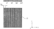
図示された実施の形態の反射型リニアスケール10は、反射型リニア位相格子として形成されている。この反射型リニア位相格子の反射光が、光ファイバ走査ヘッド20によって走査される。この反射型リニアスケール10は、測定方向xに周期的に配置された、異なる移相作用を呈する複数の目盛領域から構成される。これらの目盛領域は、長方形を成す。この場合、長方形の長手軸が、示されたy方向に沿って延在する。このy方向は、当該反射型リニアスケール平面内で測定方向xに対して垂直に配向されている。
The reflective
当然に、図示された実施の形態とは違って、反射型ロータリースケールも、ラジアル目盛又はドラム目盛として本発明のエンコーダで使用され得る。 Of course, unlike the illustrated embodiment, a reflective rotary scale can also be used in the encoder of the present invention as a radial or drum scale.
反射型リニアスケール10は、光ファイバ30を通じて照射ビーム束を供給することによって照射される。このため、スペクトルを広帯域化した光源40が、光ファイバ30の、反射型リニアスケールに対向していない端部に配置されている。この光源40の放射光が、コリメートレンズ41、ビームスプリッタ42及びカップリングレンズ43としてのカップリング手段を通じてこの光ファイバ30の中に入射される。例えば、850nmの中心波長で放射し且つ60nmのスペクトル幅を有する赤外線発光ダイオードが、十分に広い帯域の放射スペクトルを有する適切な光源40として考えられる。
The reflective
光源40の活性面が、カップリングレンズ43の焦点距離とコリメートレンズ41の焦点距離との図示された関係を成す配置によって光ファイバ30の入射面内に投影される。この場合、光が、最大許容光出力で入射するように、当該投影倍率が、最適化され得る。
The active surface of the
さらに、光源40のほかに、検出装置50も、光ファイバ30の、反射型リニアスケールに対向していない端部に設けられている。複数の位相差走査信号が、この検出装置50によって、供給された複数の重畳部分ビーム束から生成される。反射型リニアスケール10によって反射されて重畳されたこれらの部分ビーム束は、光ファイバ30を通じて検出装置50に供給される。この検出装置50の詳細な構成については、別に記載されている。当該位相差走査信号が、この検出装置50から−図示されなかった−測位装置に供給される。この測位装置は、相対移動する物体の所在地又は位置を制御する目的で当該位相差走査信号を利用する。
Further, in addition to the
したがって、特に光源40及び検出装置50のような、本発明のエンコーダの様々な能動部品が、実際の測定地点から空間的に離れて配置されていて、光ファイバ30だけを通じてこの測定地点に光学式に結合されている。すなわち、一方では、これらの能動部品に対する悪影響の最小化が保証されていて、他方では、受動的な光ファイバ走査ヘッド20が、測定地点で非常にコンパクトに構成され得る。
Accordingly, various active components of the encoder of the present invention, particularly the
光ファイバ30は、好ましくはマルチモード光ファイバとして形成されている。反射型リニアスケール10に向かう、照射するために利用される照射ビーム束と、反射型リニアスケール10から検出装置50の方向に向かう検出するために利用される重畳部分ビーム束との双方が、当該光ファイバ30を通じて伝送可能である。
The
第1の実施の形態に関して以下で詳しく説明される光ファイバ走査ヘッド20の構成が、本発明にとって重要である。図1から分かるように、この実施の形態では、光ファイバ走査ヘッド20は、光ファイバ30の、反射型リニアスケール側の端部の前方に配置されている走査板21と、レンズ22としての屈折光学素子とを有する。この場合、このレンズ22は、光ファイバ30と光ファイバ走査ヘッド20内の走査板21との間に配置されている。この光ファイバの出射面から入射するビーム束が、レンズ22を通じて、光学軸OAに沿った光ファイバ走査ヘッド10の方向の経路上でコリメートされる、又は、光ファイバ走査ヘッド10の方向からレンズ22に向かって入射する部分ビーム束が、このレンズ22を通じて、光ファイバ30の中に再び入射される、つまりこの光ファイバの入射面上に集光される。
The configuration of the optical
透明なガラス製支持基板が、走査板21として使用される。第1透過格子23が、当該支持基板の、光ファイバ30に面した側(上面)に配置されていて、第2透過格子24が、反射型リニアスケール10に面した側(下面)に配置されている。
A transparent glass support substrate is used as the
レンズ22を通じてコリメートされて第1透過格子23上に入射するビーム束が、この第1透過格子23を通じて少なくとも2つの回折部分ビーム束に分割される。これらの回折部分ビーム束は、当該分割後に走査板21内でこの走査板の法線に対して非対称に引き続き伝播する。すなわち、この実施の形態では、例えば、図1に示された光学軸OAが、当該走査板の法線を示す。第1透過格子23は、ブレーズド位相格子として形成されている。このブレーズド位相格子は、最大の回折効率を+1次及び−2次の回折次数で有する。したがって、これらの両回折次数は、走査ビーム路内の、非対称に引き続き伝播する部分ビーム束を示す。これらの部分ビーム束は、位相差に関係する走査信号を生成するために利用され、分割と再集束のとの間に異なる光路を進行する。
The beam bundle collimated through the
分割された部分ビーム束は、走査板21の透過後に、この走査板21の、反射型リニアスケール10に面している片面に配置されている第2透過格子24上に到達する。次いで、これらの部分ビーム束が、当該走査板の法線に対して対称にこの走査板21とこの反射型リニアスケール10との間を引き続き伝播するように、第2透過格子24が、第1透過格子23から入射する部分ビーム束を回折させる。さらに、これらの部分ビーム束が、いわゆるリトロー角度を成して反射型リニアスケール10上に入射するように、これらの部分ビーム束は、第2透過格子24によって回折される。これらの部分ビーム束が、リトロー角度を成して反射型リニアスケール10上に入射する結果、これらの部分ビーム束は、同じ角度で反射型リニアスケール10から走査板21に向かって戻るように反射される。これらの部分ビーム束は、当該同じ角度でこの走査板21に向かって入射する。第2透過格子24は、同様にブレーズド位相格子として形成されている。つまり、この位相格子の最大回折効率が、+1次及び−1次の回折次数で最適化されている。
The divided partial beam bundle reaches the second transmission grating 24 disposed on one side of the
これらの部分ビーム束は、反射型リニアスケール10での戻り反射後に、走査板21の下面の第2透過格子24を新たに透過し、第1透過格子23で再集束するまで、走査板21の法線に対して非対称にこの走査板内で伝播する。この透過格子に対して+1次及び−2次の回折次数で分割された部分ビーム束が、走査板21の上面の第1透過格子23で重畳干渉光になる。次いで、最終的には、当該重畳された一対の部分ビーム束が、光学軸OAに沿ってレンズ22の方向に伝播し、このレンズ22を通じて光ファイバ30中に入射される。
These partial beam bundles are transmitted through the second transmission grating 24 on the lower surface of the
独国特許出願公開第102007024349号明細書で既に開示されているように、本発明は、位相差走査信号を波長に応じてコード化することが提唱されている。このことは、当該位相差走査信号が、異なる波長を有する回折スペクトルの複数の成分から生成されることを意味する。したがって、第1透過格子での分割と再集束との間に信号生成される複数の部分ビーム束の非対称なビーム路と、こうして生成される異なる光路長とが、当該位相差走査信号のために重要である。分割と再集束との間のこれらの部分ビーム束が、当該異なる光路長を進行する。したがって、当該ビーム路のこの領域内の非対称なビーム路が、分割されたこれらの部分ビーム束間に、波長に関係する位相差をもたらす。 As already disclosed in DE 102007024349, the invention proposes to code the phase-difference scanning signal according to the wavelength. This means that the phase difference scanning signal is generated from a plurality of components of the diffraction spectrum having different wavelengths. Therefore, the asymmetric beam paths of the plurality of partial beam bundles that are generated during splitting and refocusing in the first transmission grating and the different optical path lengths thus generated for the phase difference scanning signal is important. These partial beam bundles between splitting and refocusing travel through the different optical path lengths. Thus, the asymmetric beam path in this region of the beam path results in a wavelength-related phase difference between the split partial beam bundles.
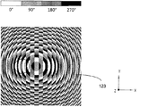
位相差走査信号を波長に応じてコード化するため、さらに、第1透過格子23が、周期的な位相変化Δp(x)を測定方向xに有することが提唱されている。第1透過格子23のこの周期性は、図2aの第1透過格子23の縦断面図とその概略平面図との双方から分かる。第1透過格子23の、4つのステップに量子化して形成されている一目盛周期TPG1内には、図示された実施の形態では、異なる4つの移相目盛領域が設けられている。当該4つの移相目盛領域は、位相0°、90°、180°、270°を有する位相差走査信号に割り当てられている。つまり、図2aの表示では、これらの異なる移相目盛領域は、異なるハッチングで表示されている。当然に、この第1透過格子は、4つより多いステップ、例えば8つのステップで量子化されて形成されてもよい。 In order to code the phase difference scanning signal according to the wavelength, it is further proposed that the first transmission grating 23 has a periodic phase change Δp (x) in the measurement direction x. This periodicity of the first transmission grating 23 can be seen from both a longitudinal sectional view of the first transmission grating 23 in FIG. 2a and a schematic plan view thereof. In the one scale period TP G1 formed by quantization in four steps of the first transmission grating 23, in the illustrated embodiment, four different phase shift scale regions are provided. The four phase shift scale areas are assigned to phase difference scanning signals having phases of 0 °, 90 °, 180 °, and 270 °. That is, in the display of FIG. 2a, these different phase shift scale areas are displayed with different hatching. Of course, this first transmission grating may be formed quantized in more than four steps, for example eight steps.
この場合、測定方向xに沿った第1透過格子23の位相変化Δp(x)は、第1の実施の形態では、以下のように表記され得る。 In this case, the phase change Δp (x) of the first transmission grating 23 along the measurement direction x can be expressed as follows in the first embodiment.
![]()
![]()
(方程式1)
m:=2、0、−2、−3、...(第1透過格子の+1次の回折次数以外に使用される非対称な別の回折次数;上記では、m=−2)
TPG1:=第1透過格子の目盛周期
(Equation 1)
m: = 2, 0, -2, -3,. . . (Another asymmetric diffraction order used other than the + 1st diffraction order of the first transmission grating; m = −2 above)
TP G1 : = Scale period of the first transmission grating
また、図1の横断面図及び図2bの平面図から見て取れるように、走査板の下面の第2透過格子24は、4つのステップに量子化して形成されている。この第2透過格子24の1つの目盛周期TPG2内では、同様に異なる4つの移相目盛領域が設けられている。当該4つの移相目盛領域は、位相0°、90°、180°、270°を有する4つの位相差走査信号に割り当てられている。 Further, as can be seen from the cross-sectional view of FIG. 1 and the plan view of FIG. 2b, the second transmission grating 24 on the lower surface of the scanning plate is quantized into four steps. In the second one graduation period TP G2 of transmission grating 24, four phase shift graduation regions different in the same manner is provided. The four phase shift scale areas are allocated to four phase difference scanning signals having phases of 0 °, 90 °, 180 °, and 270 °.
本発明の光学式エンコーダの実施の形態を具体的に構成するためには、以下で示すように、関与するビーム束、部分ビーム束及び格子の波数ベクトルつまりkベクトルを検討することが有益である。 To specifically configure an embodiment of the optical encoder of the present invention, it is beneficial to consider the beam bundles involved, the partial beam bundles, and the wavenumber vector or k-vector of the grating, as shown below. .
すなわち、第1透過格子23で発生する+1次の回折次数の部分ビーム束のkベクトルは、k1で示される。したがって、当該同じ透過格子23に対する−2次の回折次数のkベクトルは、−2k1になる。kベクトルk2を有する第2透過格子24では、その他のビーム路で必要な対称性に起因して、kベクトルk2=k1/2が、2つの部分ビーム束に対して加算される。したがって、kStrahl=3k1/2に応じたkベクトル及びkStrahl=−3k1/2に応じたkベクトルが、反射型リニアスケール10の方向に引き続き伝播する当該両部分ビーム束に対して発生する。それ故に、これらのkベクトルkStrahlの絶対値が、このビーム路部分内の当該両部分ビーム束に対して等しい。リトローの条件を満たすためには、反射型リニアスケール10のkベクトルkMの絶対値が、それぞれのkベクトルkStrahlの絶対値の2倍の大きさに選択される必要がある。すなわち、kM=3k1が成立する必要がある。
That, k vectors +1 diffraction order of partial light beams generated by the first transmission grating 23 is indicated by k 1. Therefore, k vectors -2 diffraction order with respect to the same transmission grating 23 will -2k 1. In the second transmission grating 24 having a k-vector k 2, due to other required symmetry beam path, k vector k 2 = k 1/2 is added to the two partial beam bundles. Therefore, k Strahl = 3k 1/2 k vectors and k Strahl = k vectors corresponding to -3K 1/2 corresponding to the occurrence with respect to the two partial beam bundles to continue propagating in the direction of the reflection type
第1透過格子23の上述した構成の代わりに、走査板21内で引き続き伝播するその他の非対称な回折次数に対して、すなわち−2次及び+1次の回折次数に対してではなくて、その他の非対称な回折次数の組み合わせ、例えば、0次及び1次の回折次数又は+1次及び−3次の回折次数等に対して、この第1透過格子23を最適化することが提唱され得る。例えば、+1次の回折次数以外で、−2次の回折次数の代わりに、以下ではm次の回折次数と呼ばれる別の回折次数が使用される場合、走査板21の下面上の第2透過格子24のkベクトルk2に対して、
Instead of the above-described configuration of the first transmission grating 23, other non-symmetric diffraction orders that continue to propagate in the
![]()
![]()
(方程式2)
k2:=第2透過格子のkベクトル
k1:=第1透過格子のkベクトル
m:=2、0、−2、−3、...(第1透過格子の+1次の回折次数以外に使用される非対称な別の回折次数;上記では、m=−2)
が成立する。
(Equation 2)
k 2 : = k vector of the second transmission grating k 1 : = k vector of the first transmission grating m: = 2, 0, −2, −3,. . . (Another asymmetric diffraction order used other than the + 1st diffraction order of the first transmission grating; m = −2 above)
Is established.
したがって、反射型リニアスケール10上に照射される2つの部分ビーム束のkベクトルkStrahlに対して、
Therefore, for the k vector k Strahl of the two partial beam bundles irradiated on the reflective
![]()
![]()
(方程式3)
kStrahl:=反射型リニアスケール10上に照射される2つの部分ビーム束のkベクトル
k2:=第2透過格子のkベクトル
k1:=第1透過格子のkベクトル
m:=2、0、−2、−3、...(第1透過格子の+1次の回折次数以外に使用される非対称な別の回折次数;上記では、m=−2)
が成立する。
(Equation 3)
k Strahl : = k vector of two partial beam bundles irradiated on the reflective linear scale 10 k 2 : = k vector of the second transmission grating k 1 : = k vector m of the first transmission grating m: = 2, 0 , -2, -3,. . . (Another asymmetric diffraction order used other than the + 1st diffraction order of the first transmission grating; m = −2 above)
Is established.
したがって、 Therefore,
![]()
![]()
(方程式4)
kM:=反射型リニアスケールのkベクトル
k1:=第1透過格子のkベクトル
m:=2、0、−2、−3、...(第1透過格子の+1次の回折次数以外に使用される非対称な別の回折次数;上記では、m=−2)
による反射型リニアスケール10のkベクトルkMの絶対値が得られる。
(Equation 4)
k M : = k vector of reflective linear scale k 1 : = k vector of first transmission grating m: = 2, 0, −2, −3,. . . (Another asymmetric diffraction order used other than the + 1st diffraction order of the first transmission grating; m = −2 above)
The absolute value of the k vector k M of the reflective
k1が、方程式4から求まる。 k 1 is obtained from Equation 4.
![]()
![]()
(方程式4a)
これに応じて、第1透過格子の目盛周期TPG1及び第2透過格子の目盛周期TPGP2に対して、
(Equation 4a)
Accordingly, for the scale period TP G1 of the first transmission grating and the scale period TP GP2 of the second transmission grating,
![]()
![]()
(方程式4b)
及び
(Equation 4b)
as well as
![]()
![]()
(方程式4c)
kM:=反射型リニアスケールのkベクトル
k1:=第1透過格子のkベクトル
m:=2、0、−2、−3、...(第1透過格子の+1次の回折次数以外に使用される非対称な別の回折次数;上記では、m=−2)
(Equation 4c)
k M : = k vector of reflective linear scale k 1 : = k vector of first transmission grating m: = 2, 0, −2, −3,. . . (Another asymmetric diffraction order used other than the + 1st diffraction order of the first transmission grating; m = −2 above)
反射型リニアスケール10の目盛周期TPMが、例えばTPM=4μmに選択される場合、方程式(4b)においてm=−2のときに、第1透過格子23の目盛周期TPG1が、TPG1=12μmに選択され、方程式(4c)にしたがって、第2透過格子24の目盛周期TPG2が、TPG2=24μmに選択され得る。
If graduation period TP M of the reflection type
既に上述したように、非常に小さい目盛周期TPMを有する反射型リニアスケールの可能な走査のほかに、走査信号の生成が、反射型リニアスケール10と光ファイバ走査ヘッド20との間の走査距離の変動にほとんど関係ないことが、本発明の装置のさらなる利点として奏される。当該利点は、上記両部分ビーム束が、第2透過格子24と反射型リニアスケール10との間で走査板の法線に対して対称に伝播することに起因する。実際に対称な回折次数を有する2つの部分ビーム束が、反射型リニアスケール10に照射されるために、干渉するこれらの部分ビーム束間の光路差が、当該走査距離に関係しない。
As already mentioned above, in addition to the possible scanning of the reflection type linear scale which has a very small graduation period TP M, generation of the scanning signal, the scanning distance between the reflection type
本発明の光学式エンコーダでは、位相差走査信号が、照射スペクトルの異なる複数のスペクトル成分から生成される。当該位相差走査信号の生成を、希望した数の位相差走査信号に対して可能にするためには、或る程度の検討が、当該方式を実現するために必要である。すなわち、当該検討のためには、最初に、照射スペクトルの異なる波長λ1、λ2から成る2つの信号の位相差Δp(λ1、λ2)を、信号周期で表記することが必要である。この関係は、第1の実施の形態では以下のようになる。 In the optical encoder of the present invention, the phase difference scanning signal is generated from a plurality of spectral components having different irradiation spectra. In order to enable generation of the phase difference scanning signal for a desired number of phase difference scanning signals, a certain degree of study is necessary to realize the method. That is, for the examination, first, it is necessary to express the phase difference Δp (λ 1 , λ 2 ) of two signals composed of wavelengths λ 1 and λ 2 having different irradiation spectra by a signal period. . This relationship is as follows in the first embodiment.

(方程式5)
λ1、λ2:=照射スペクトルから成る異なる波長
m:=2、0、−2、−3、...(第1透過格子の+1次の回折次数以外に使用される非対称な別の回折次数;上記では、m=−2)
nref1、nref1:=波長λ1、λ2のときの走査板の分散に関係する屈折率
TPG1:=第1透過格子の目盛周期
dAp:=走査板の厚さ
(Equation 5)
λ 1, λ 2: = wavelength different consisting irradiation spectrum m: = 2,0, -2, -3 ,. . . (Another asymmetric diffraction order used other than the + 1st diffraction order of the first transmission grating; m = −2 above)
n ref1 , n ref1 : = refractive index TP G1 related to dispersion of the scanning plate at wavelengths λ 1 and λ 2 : = scale period d Ap of the first transmission grating: = thickness of the scanning plate
以下に、本発明の光学式エンコーダの第1の実施の形態のための具体的な構成例を説明する。 Below, the specific structural example for 1st Embodiment of the optical encoder of this invention is demonstrated.
この場合、850nmの中心波長と60nmのスペクトル幅とを有する赤外線発光ダイオードが、光源として使用される。4つの位相差走査信号が、出力側で取得されなければならない場合、当該光源の全波長領域から成るこれらの4つの信号成分の各々の二重走査が実行される。すなわち、それぞれ90°位相差のある8つの信号成分が、当該使用可能な60nmの光源のスペクトル領域から取得される必要がる。受信機側の、対応する高いスペクトル分解能によって、当該信号成分の、さらに高い分解能の走査も考えられる。その結果、光源のスペクトルが、例えば温度の影響によって変化しても、より良好な安定性が得られる。上記に提唱されている二重走査のときに、当該8つの信号成分を生成するためには、30nmの波長差のときに、1(360°)の位相差が発生するように、走査板21の厚さdAp及び/又はこの走査板21上に配置された透過格子の格子パラメータが決定される必要がある。具体的な実施の形態では、クウォーツが、走査板21用の材料として使用される(nref≒1.452)。さらに、上記に挙げられた目盛周期TPM=4μm、TPG1=12μm、TPG2=24μmが、反射型リニアスケール10並びに第1透過格子23及び第2透過格子24に対して適用される。走査板21の厚さdApに関する上記方程式(5)を解くと、dAp=2.28mmに相当する当該走査板に必要な厚さdApが求まる。したがって、対応する位相差が、方程式(5)にしたがって波長変化ごとに求まるように、走査板21の厚さdAp及び/又はこの走査板21上に配置された透過格子の格子パラメータが、本発明のエンコーダにおいて決定される。
In this case, an infrared light emitting diode having a center wavelength of 850 nm and a spectral width of 60 nm is used as the light source. If four phase difference scanning signals have to be acquired on the output side, a double scan of each of these four signal components consisting of the full wavelength region of the light source is performed. That is, eight signal components each having a 90 ° phase difference need to be obtained from the spectral region of the usable 60 nm light source. Due to the corresponding high spectral resolution at the receiver side, a higher resolution scan of the signal component is also conceivable. As a result, even when the spectrum of the light source changes due to the influence of temperature, for example, better stability can be obtained. In order to generate the eight signal components during the double scanning proposed above, the
図1には、本発明の光学式エンコーダの上述した構成要素のほかに、さらに、波長に応じてコード化された位相差走査信号を検出するために使用される検出装置50が示されている。
In addition to the above-described components of the optical encoder of the present invention, FIG. 1 further shows a
このため、光ファイバ30の、反射型リニアスケールに面しない端部に配置されている当該検出装置50は、大まかに示された、重畳された部分ビーム束を波長に応じて分光するための分光手段51を有する。当該部分ビーム束は、光ファイバ30を通じて検出装置50の方向に伝送される。この例では、分光手段51が、回折格子型の分散素子として形成されている。光が、分光手段51の後方に配置されたレンズ52を通じて、構造化された光検出器53上に集光される。ここでは、この光検出器53は、8つの個別検出素子から構成される。この場合、1つの所定の波長の当該投影された光は、集光面内で円を形成する。この円の直径は、光ファイバ30のファイバコアの直径と、レンズ52とカップリングレンズ43との焦点距離比との積によって算出される。それ故に、当該光ファイバの端部の複数の円形投影光が、空間的に分離して存在するように、すなわち別々に検出可能であるように、分光手段51の分散度が十分に大きくなくてはならない。本発明の実施の形態では、1つの位相差は、30nm/360°に相当する。
Therefore, the
例えば、90°ずつ移相されている4つの走査信号が生成されるときは、これに応じて、7.5nmのスペクトル分解能が必要である。この場合、各走査信号は、360°の位相差ごとに繰り返し走査され得る。こうして、全ての光源スペクトルが利用され得る一方で、例えば温度誘導された波長シフトが、生成された走査信号の振幅にほとんど影響しない。 For example, when four scanning signals that are phase shifted by 90 ° are generated, a spectral resolution of 7.5 nm is required accordingly. In this case, each scanning signal can be repeatedly scanned for every 360 ° phase difference. Thus, while all light source spectra can be utilized, for example, a temperature induced wavelength shift has little effect on the amplitude of the generated scanning signal.
必要に応じて、検出装置50内にさらに追加して配置され得る、信号を処理するためのその他の構成要素は、図1には示されていない。例えば、増幅器、A/D変換器等が、当該その他の構成要素に属される。走査新号が、さらなる処理のために図示されなかった後続の電子機器に対して伝送される前に、当該走査信号は、上記その他の構成要素によってさらに演算処理されて評価される。
Other components for processing the signal, which may be additionally arranged in the
また、十分な分解能を小型の評価装置で達成するため、光路内に連続して配置された複数の回折格子を分光手段51として使用することが可能である。このため、これらの回折格子が、ほぼリトロー角度を成して照射されるときに、これらの回折格子の高い回折効率が達成され得る。この条件下では、カップリングレンズ43の焦点距離fが、特に以下のように決定され得る。
In addition, in order to achieve sufficient resolution with a small evaluation device, a plurality of diffraction gratings continuously arranged in the optical path can be used as the spectroscopic means 51. For this reason, the high diffraction efficiency of these diffraction gratings can be achieved when these diffraction gratings are irradiated at approximately the Littrow angle. Under this condition, the focal length f of the
![]()
![]()
(方程式6)
λ:=平均波長
d:=回折格子の格子定数
Df:=光ファイバの端部の直径
N:=使用された回折格子の数
Δλ:=必要な波長分解能
(Equation 6)
λ: = average wavelength d: = grating grating constant D f : = diameter of optical fiber end N: = number of diffraction gratings used Δλ: = required wavelength resolution
さらに、入射光が光ファイバの端部で反射することによって検出路内に到達する連続光成分を減少させることが好ましい。当該連続光の減少は、反射防止膜を光ファイバの端部上にコーティングすることによって達成され得る。この代わりに又はこれに加えて、光ファイバの端部を斜め研磨することによって、入射時に反射した光が、検出路内に到達することが阻止され得る。 Furthermore, it is preferable to reduce the continuous light component reaching the detection path by reflecting the incident light at the end of the optical fiber. The continuous light reduction can be achieved by coating an anti-reflective coating on the end of the optical fiber. Alternatively or additionally, by obliquely polishing the end of the optical fiber, the light reflected upon incidence can be prevented from reaching the detection path.
この代わりに又はこれに加えて、本発明の装置では、さらに、未変調スペクトルが、一緒に測定され得る。このため、斜め研磨された光ファイバの端部で反射された光が、例えば、当該出射側の光ファイバの端部とカップリングレンズとの間のプリズム又は回折素子によって偏光され得る結果、当該反射された光は、実際にはこの光ファイバの端部に対してずれた地点から出射される。その結果、変調スペクトルの隣に空間的にずれるように、未変調スペクトルが、検出素子基板の平面内でさらに取得され得る。当該未変調スペクトルは、追加の検出素子によって検出可能である。こうして取得された情報は、照射スペクトルの変化から生じる信号誤差を補正するために利用され得る。 Alternatively or additionally, in the device according to the invention, the unmodulated spectrum can also be measured together. Therefore, the light reflected at the end of the obliquely polished optical fiber can be polarized by, for example, a prism or a diffractive element between the end of the optical fiber on the emission side and the coupling lens. The emitted light is actually emitted from a point shifted from the end of the optical fiber. As a result, an unmodulated spectrum can be further acquired in the plane of the detection element substrate so as to be spatially shifted next to the modulated spectrum. The unmodulated spectrum can be detected by an additional detection element. The information thus obtained can be used to correct signal errors resulting from changes in the illumination spectrum.
第1の実施の形態と僅かに異なる本発明の光学式エンコーダの第2の実施の形態が、図3にその一部を示されている。この場合、測定地点側の構成要素だけが示されている。すなわち、光ファイバ走査ヘッド120及び反射型リニアスケール110が示されている。光ファイバ130の、この反射型リニアスケールに面しない端部側の別の構成要素は、図示していない。つまり、当該別の構成要素は、第1の実施の形態と同一である。以下に、第1の実施の形態との決定的な相違点だけを説明する。
A second embodiment of the optical encoder according to the present invention, which is slightly different from the first embodiment, is shown in part in FIG. In this case, only the components on the measurement point side are shown. That is, an optical
すなわち、光ファイバ走査ヘッド120の第2の実施の形態では、独立したレンズが、走査板121の上面上の、光ファイバ130と第1透過格子123との間にもはや存在しない。第1の実施の形態とは違って、このレンズに対応する光学機能が、第1透過格子123にさらに組み込まれている。当該構成は、第1透過格子123が、既に上述した光学機能のほかに、コリメート作用をも光ファイバ130から入射するビーム束に及ぼすことを意味する。反対方向に伝播する重畳部分ビーム束が、当該第1透過格子123を透過することによって光ファイバ130内に入射される、すなわち対応する光ファイバの入射面内に集光される。第1の実施の形態に比べてさらにコンパクトな光ファイバ走査ヘッド120が構成される。さらに、本発明の装置の製造時の独立したレンズに関する調整コストがかからない。
That is, in the second embodiment of the optical
図4は、当該追加の光学機能を有する第1透過格子123で発生する位相変化の平面図である。 FIG. 4 is a plan view of a phase change generated in the first transmission grating 123 having the additional optical function.
上記以外の位相差走査信号及びその他の詳細は、第1の実施の形態の説明に記載されている。 The phase difference scanning signal other than the above and other details are described in the description of the first embodiment.
本発明の光学式エンコーダの第3の実施の形態が、図5及び図6に示されている。以下に、この第3の実施の形態の説明では、第1の実施の形態との決定的な相違点について最初に言及する。 A third embodiment of the optical encoder of the present invention is shown in FIGS. Hereinafter, in the description of the third embodiment, a decisive difference from the first embodiment will be mentioned first.
図5には、再度、測定地点の領域だけが示されている。図6は、第1透過格子の位相変化を大まかに示す。光を光ファイバ230内に入射させること、及び、重畳部分ビーム束を検出することは、既に説明した実施の形態と同様である。
FIG. 5 again shows only the area of the measurement point. FIG. 6 roughly shows the phase change of the first transmission grating. Injecting light into the
光ファイバ走査ヘッド220内の光ファイバ230から出射するビーム束が、第1の実施の形態のように、光路上のレンズ222を透過して反射型リニアスケール210の方向に光学軸OAに沿ってコリメートされる。次いで、当該コリメートされたビーム束は、偏光子225を透過する。当該ビーム束は、この偏光子225を透過すると直線偏光したものになる。この場合、当該偏光方向は、測定方向xに配向されている。引き続き、当該直線偏光されたビーム束は、走査板221、つまり第1透過格子223上に照射される。この第1透過格子223は、この走査板221の、光ファイバ230に面した面上に配置されている。この実施の形態では、上述の2つの実施の形態と違って、入射したビーム束が、第1透過格子223を透過して+1次の回折次数の部分ビーム束と−1次の回折次数の部分ビーム束とに分割される。この場合、第1透過格子223は、位相格子として形成されていて、且つ目盛周期TPG1を有する。この目盛周期TPG1は、反射型リニアスケール210の目盛周期TPMの半分に相当する。
The beam bundle emitted from the
次いで、当該分割された複数の部分ビーム束は、走査板221を伝播し、複屈折要素226内に到達する。この複屈折要素226は、この走査板221の、反射型リニアスケール210に面した面上に配置されている。次いで、当該分割された複数の部分ビーム束は、この走査板221のこの複屈折要素226内で非対称に引き続き伝播する。これらの部分ビーム束の、測定方向xの直線偏光に起因して、非偏光(自然光)(ordentlichen Strahlen)の伝播が、この複屈折要素226内で抑制されるように、当該非対称な伝播は、この複屈折要素226の選択された偏光方向によって引き起こされる。さらに、この複屈折要素226の楕円偏光が、走査板の法線に対して0°以外で且つ90°以外の角度を成して生成される。したがって、第1透過格子223の回折地点において+1次の回折次数と−1次の回折次数とを成す2つの偏光(ausserordentlichen Strahlen)の屈折率が異なる。当該屈折率が異なるのは、当該2つの部分ビーム束の伝播方向に対する複屈折要素226の主軸の相対角度が異なることに起因する。
Then, the divided partial beam bundles propagate through the
本発明のエンコーダの上記の実施の形態を具体的に構成するためには、同様に、信号周期で表記された、異なる波長λ1、λ2に基づく2つの信号の位相差Δp(λ1、λ2)を知ることが必要である。この実施の形態では、この位相差Δp(λ1、λ2)は、複屈折要素226の厚さddEに比例し、以下のように表記される。
In order to specifically configure the above-described embodiment of the encoder of the present invention, similarly, the phase difference Δp (λ 1 , λ 2) of two signals based on different wavelengths λ 1 , λ 2 , expressed in signal periods. It is necessary to know λ 2 ). In this embodiment, the phase difference Δp (λ 1 , λ 2 ) is proportional to the thickness d dE of the
(方程式7)
λ1、λ2:=照射スペクトルの異なる波長
ddE:=複屈折要素の厚さ
β1、β2:=照射角度。当該分割された2つの部分ビーム束が、上面の法線に対してこの照射角度を成して複屈折要素上に入射する。
TPG1:=第1透過格子の目盛周期
nr:=偏光の、波長と照射方向とに関係する複屈折要素の屈折率
(Equation 7)
λ 1 , λ 2 : = wavelengths with different irradiation spectra d dE : = birefringence element thicknesses β 1 , β 2 : = irradiation angle. The two divided partial beam bundles are incident on the birefringent element at this irradiation angle with respect to the normal of the upper surface.
TP G1 : = scale period n r of the first transmission grating: = refractive index of the birefringent element related to the wavelength and irradiation direction of the polarized light
この場合、屈折率nrは、それぞれの波長λ1、λ2と照射方向β1、β2との双方に関係する。これらの異なる両照射方向β1、β2は、第1透過格子223で生じる±1次の回折次数から得られる。また、屈折率nrは、照射方向に関係するので、β1及びβ2は、複屈折媒体のための以下の屈折式から零点を求めることによって計算される。 In this case, the refractive index n r is related to both the wavelengths λ 1 and λ 2 and the irradiation directions β 1 and β 2 . These two different irradiation directions β 1 and β 2 are obtained from the ± 1st order diffraction orders generated in the first transmission grating 223. Also, since the refractive index n r is related to the irradiation direction, β 1 and β 2 are calculated by obtaining a zero from the following refraction formula for the birefringent medium.
![]()
![]()
(方程式8)
λi=照射スペクトルの異なる波長
nr:=偏光の、波長と照射方向とに関係する複屈折要素の屈折率
β1,2:=角度。当該分割された2つの部分ビーム束が、上面の法線に対してこの角度を成して複屈折要素を伝播する。
γ:=上面の法線に対する複屈折要素の材料の配向角
(Equation 8)
λ i = wavelength n r with different irradiation spectrum: = refractive index of a birefringent element related to wavelength and irradiation direction of polarized light β 1,2 : = angle. The two split partial beam bundles propagate through the birefringent element at this angle with respect to the top normal.
γ: = Orientation angle of the material of the birefringent element with respect to the normal of the upper surface
したがって、当該照射方向に関係する屈折率nrは、 Therefore, the refractive index n r related to the irradiation direction is
![]()
![]()
(方程式9)
によって計算される。
nr:=偏光の、波長と照射方向とに関係する複屈折要素の屈折率
n0:=非偏光の屈折率
ne:=偏光の屈折率
Θ:=ビーム方向β1、β2と複屈折要素の配向角との成す角度
(Equation 9)
Calculated by
n r : = refractive index of the birefringent element related to wavelength and irradiation direction of polarized light n 0 : = refractive index of non-polarized light n e : = refractive index of polarized light Θ: = reverse refractive index of beam directions β 1 and β 2 Angle formed with the orientation angle of the refractive element
当該屈折率n0、neは、それぞれの波長のときに対応する複屈折材料の分散式から算出され得る。 The refractive index n 0, n e can be calculated from the dispersion equation birefringent material corresponding at each wavelength.
以下に、本発明の光学式エンコーダの第3の実施の形態のための具体的な構成例を説明する。 Below, the specific structural example for 3rd Embodiment of the optical encoder of this invention is demonstrated.
同様に、850nmの中心波長と60nmのスペクトル幅とを有する光源が使用される。方解石が、複屈折要素26用の材料として設けられている。 Similarly, a light source having a central wavelength of 850 nm and a spectral width of 60 nm is used. Calcite is provided as a material for the birefringent element 26.
一般に、複屈折要素226に必要な厚さddEは、反射型リニアスケール210の目盛周期TPMが小さくなると共に減少する。何故なら、伝播した2つの部分ビーム束の±1次の回折次数の回折角度が、複屈折要素226内で大きく相違するからである。それ故に、以下では、第1透過格子223の1つの目盛周期TPG1は、TPG1=4μmに相当する。反射型リニアスケール210の目盛周期TPMは、TPM=2μmになり、走査信号の1つの信号周期は、1μmに相当する。さらに、配向角γ=45°が採用される。同様に、1つの位相差が、30nm/360°に相当しなければならない場合は、ddE=3.71mmに相当する複屈折要素226の厚さddEが必要である。
In general, the thickness d dE required
複屈折要素226のさらによりコンパクトな構造又はより薄い厚さddEは、AgGaSe2(銀ガリウムセレナイト)を複屈折要素として使用することによって達成される。上述した同じ回折角度の下では、ddE=0.47mmに相当する複屈折要素226の厚さddEが得られる。
An even more compact structure or thinner thickness d dE of the
最後に、本発明の光学式エンコーダの第4の実施の形態を図7及び図8に基づいて説明する。 Finally, a fourth embodiment of the optical encoder of the present invention will be described with reference to FIGS.
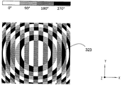
第4の実施の形態は、上述した第3の実施の形態を基礎とし、さらに、第2の実施の形態で既に提唱されたように、レンズ222の光学機能が、走査板321の上面上の第1透過格子323に組み込まれるという点だけが、第3の実施の形態と相違する。当該第1透過格子323は、ビーム束を分割する光学機能のほかに、コリメート作用をも光ファイバ330から入射する当該ビーム束に及ぼす。反対方向に伝播する重畳部分ビーム束が、当該第1透過格子323を透過することによって光ファイバ330内に入射される、すなわち対応する光ファイバの入射面内に集光される。同様に、第3の実施の形態に比べてさらによりコンパクトな光ファイバ走査ヘッド320が構成される。
The fourth embodiment is based on the third embodiment described above, and furthermore, as already proposed in the second embodiment, the optical function of the
図8は、当該追加の光学機能を有する第1の透過格子323で発生する位相変化の平面図である。 FIG. 8 is a plan view of a phase change generated in the first transmission grating 323 having the additional optical function.
上記以外の位相差走査信号及びその他の詳細は、第3の実施の形態又はその他の実施の形態の説明に記載されている。 The phase difference scanning signal other than the above and other details are described in the description of the third embodiment or other embodiments.
当然に、本発明は、上記の説明した実施の形態以外に、さらに変更可能である。 Naturally, the present invention can be further modified in addition to the embodiment described above.
適切な走査板の第2の実施の形態の説明に関連して言及したように、必要に応じて、ただ1つの広帯域光源の代わりに、異なる個別波長を有する複数の個別光源から成る組み合わされた光源又は光源装置を使用してもよい。この場合、実施の形態に応じて、レーザーダイオード、垂直共振器面発光レーザ、発光ダイオード、有機発光ダイオード等が、光源として使用される。ダイクロイックミラー又は適切な分散素子を用いることで、光が、これらの異なる光源から集束し、一緒に光ファイバ内に入射され得る。 As mentioned in connection with the description of the second embodiment of a suitable scanning plate, a combination of a plurality of individual light sources having different individual wavelengths is optionally substituted for a single broadband light source. A light source or light source device may be used. In this case, a laser diode, a vertical cavity surface emitting laser, a light emitting diode, an organic light emitting diode, or the like is used as a light source according to the embodiment. By using dichroic mirrors or suitable dispersive elements, light can be focused from these different light sources and incident together into the optical fiber.
90°ずつ移相されている4つの走査信号による方式を実現することのほかに、本発明の範囲内では、当然に、120°ずつ移相されている3つの走査新号が生成される別の実施の形態も提唱され得る。つまり、この場合位にも、上述した4つの位相の方式と同様に、多重走査等が実現可能である。 In addition to realizing a system with four scanning signals that are phase shifted by 90 °, of course, within the scope of the present invention, of course, three new scanning signals that are phase shifted by 120 ° are generated. This embodiment can also be proposed. That is, in this case, multiple scanning or the like can be realized as in the above-described four-phase method.
10 反射型リニアスケール
20 光ファイバ走査ヘッド
21 走査板
22 レンズ
23 第1透過格子
24 第2透過格子
30 光ファイバ
40 光源
41 コリメートレンズ
42 ビームスプリッタ
43 カップリングレンズ
50 検出装置
51 分光手段
52 レンズ
53 光検出器
110 反射型リニアスケール
121 走査板
123 第1透過格子
124 第2透過格子
130 光ファイバ
210 反射型リニアスケール
221 走査板
222 レンズ
223 第1透過格子
225 偏光子
226 複屈折要素
310 反射型リニアスケール
320 光ファイバ走査ヘッド
323 第1透過格子
325 偏光子
326 複屈折要素
330 光ファイバ
331 走査板
DESCRIPTION OF
Claims (15)
・前記走査板(21;121;221;321)上に入射した1つのビーム束が、少なくとも2つの部分ビーム束に分割され、これらの部分ビーム束が、前記反射型リニアスケール(10;110;210;310)に照射され、次いで前記位相差走査信号を生成するために再集束して互いに干渉し、
・これらの部分ビーム束が、当該分割と当該再集束との間に異なる光路長を進行するように、前記走査板(21;121;221;321)は形成されていることを特徴とする光学式エンコーダ。 An optical encoder for generating a plurality of phase difference scanning signals related to a relative position between an optical fiber scanning head and a reflective linear scale movable in at least one measurement direction with respect to the optical fiber scanning head, In the optical fiber scanning head, a scanning plate is disposed in front of an end of the optical fiber on the reflective linear scale side, and the phase difference scanning signal is encoded according to the wavelength. In the encoder
One beam bundle incident on the scanning plate (21; 121; 221; 321) is divided into at least two partial beam bundles, and these partial beam bundles are divided into the reflective linear scale (10; 110; 210; 310) and then refocus to interfere with each other to produce the phase difference scan signal;
The scanning plate (21; 121; 221; 321) is formed so that these partial beam bundles travel different optical path lengths between the division and the refocusing. Type encoder.
・異なる波長の放射光を放射する複数の光源が、
前記光ファイバ(30;130;230;330)の、前記反射型リニアスケールに面しない端部に配置されていて、当該光源の放射光が、照射ビーム束としてカップリング手段を通じて前記光ファイバ(30;130;230;330)内に入射可能であることを特徴とする請求項1に記載の光学式エンコーダ。 One light source (40) with a broad spectrum, or a plurality of light sources that emit radiation of different wavelengths,
The optical fiber (30; 130; 230; 330) is disposed at an end of the optical fiber (30; 130; 230; 330) that does not face the reflective linear scale. 130; 230; 330). The optical encoder according to claim 1, wherein the optical encoder is capable of being incident on the optical encoder.
・再集束した前記部分ビーム束を波長に応じて分光するための分光手段(51)、及び
・複数の光電検出素子を有し、これらの光電検出素子は、当該分光された部分ビーム束を転送可能であり、且つ当該検出された部分ビーム束を電気的な位相差走査信号に変換することを特徴とする請求項5に記載の光学式エンコーダ。 A detection device (50) is disposed at an end of the optical fiber (30; 130; 230; 330) that does not face the reflective linear scale, and the detection device (50) includes:
A spectroscopic means (51) for splitting the refocused partial beam bundle according to the wavelength, and a plurality of photoelectric detection elements, which transfer the split partial beam bundle 6. The optical encoder according to claim 5, wherein the optical encoder is capable of converting the detected partial beam bundle into an electrical phase difference scanning signal.
・第1透過格子(23;123)が、前記走査板(21;121)の、前記光ファイバ(30;130)に面した面上に配置されていて、この第1透過格子(23;123)は、この第1透過格子(23;123)上に入射する前記ビーム束を少なくとも2つの回折部分ビーム束に分割し、これらの回折部分ビーム束は、前記走査板の法線に対して非対称に引き続き伝播し、
・第2透過格子(24;124)が、前記走査板(21;121)の、前記反射型リニアスケール(10;110)に面した面上に配置されていて、前記第1透過格子(23;123)からこの第2透過格子(24;124)上に入射する複数の前記部分ビーム束が、前記走査板の法線に対して互いに対称にこの走査板(21;121)とこの反射型リニアスケール(10;110)との間を伝播し、前記複数の部分ビーム束のリトロー角度を成してこの反射型リニアスケール(10;110)に照射されるように、この第2透過格子(24;124)は、前記複数の部分ビーム束を回折させることを特徴とする請求項1〜6のいずれか1項に記載の光学式エンコーダ。 The scanning plate (21; 121) is formed as a plate-like and transmissive substrate,
A first transmission grating (23; 123) is arranged on the surface of the scanning plate (21; 121) facing the optical fiber (30; 130), and the first transmission grating (23; 123). ) Divides the beam bundle incident on the first transmission grating (23; 123) into at least two diffracted partial beam bundles which are asymmetric with respect to the normal of the scanning plate. Continue to propagate,
A second transmission grating (24; 124) is arranged on the surface of the scanning plate (21; 121) facing the reflective linear scale (10; 110), and the first transmission grating (23 123) and the plurality of partial beam bundles incident on the second transmission grating (24; 124) are symmetrical to each other with respect to the normal line of the scanning plate (21; 121) and the reflection type The second transmission grating (10; 110) propagates between the linear scale (10; 110) and irradiates the reflective linear scale (10; 110) at a Littrow angle of the plurality of partial beam bundles. The optical encoder according to any one of claims 1 to 6, wherein 24; 124) diffracts the plurality of partial beam bundles.
・第1透過格子(223;323)が、前記走査板(221;321)の、前記光ファイバ(230;330)に面した面上に配置されていて、この第1透過格子(223;323)は、この第1透過格子(223;323)上に入射する前記ビーム束を少なくとも2つの回折部分ビーム束に分割し、且つこの第1透過格子(223;323)上に入射するこのビーム束にコリメート作用を及ぼし、
・複屈折要素(226;326)が、前記走査板(221;321)の、前記反射型リニアスケール(210;310)に面した面上に配置されていて、この複屈折要素(226;326)内では、当該分割された複数の部分ビーム束が、前記走査板の法線に対して非対称に引き続き伝播し、この走査板(221;321)を離れた後に、この走査板の法線に対して互いに対称に、この走査板(221;321)と前記反射型リニアスケール(210;310)との間を伝播し、前記複数の部分ビーム束のリトロー角度を成してこの反射型リニアスケールに照射されることを特徴とする請求項1〜6のいずれか1項に記載の光学式エンコーダ。 A linearly polarized beam bundle is incident on the scanning plate (221; 321),
A first transmission grating (223; 323) is disposed on the surface of the scanning plate (221; 321) facing the optical fiber (230; 330), and the first transmission grating (223; 323) ) Splits the beam bundle incident on the first transmission grating (223; 323) into at least two diffractive partial beam bundles and the beam bundle incident on the first transmission grating (223; 323). Has a collimating effect on
A birefringent element (226; 326) is arranged on the surface of the scanning plate (221; 321) facing the reflective linear scale (210; 310), the birefringent element (226; 326) ), The divided partial beam bundles continue to propagate asymmetrically with respect to the normal of the scanning plate, and after leaving the scanning plate (221; 321), The reflective linear scale propagates between the scanning plate (221; 321) and the reflective linear scale (210; 310) symmetrically with respect to each other to form a Littrow angle of the plurality of partial beam bundles. The optical encoder according to claim 1, wherein the optical encoder is irradiated with light.
Applications Claiming Priority (4)
| Application Number | Priority Date | Filing Date | Title |
|---|---|---|---|
| DE102013201904.1 | 2013-02-06 | ||
| DE102013201904 | 2013-02-06 | ||
| DE102013222383.8 | 2013-11-05 | ||
| DE102013222383.8A DE102013222383A1 (en) | 2013-02-06 | 2013-11-05 | Optical position measuring device |
Publications (2)
| Publication Number | Publication Date |
|---|---|
| JP2014153360A true JP2014153360A (en) | 2014-08-25 |
| JP6332987B2 JP6332987B2 (en) | 2018-05-30 |
Family
ID=49998175
Family Applications (1)
| Application Number | Title | Priority Date | Filing Date |
|---|---|---|---|
| JP2014019238A Active JP6332987B2 (en) | 2013-02-06 | 2014-02-04 | Optical encoder |
Country Status (6)
| Country | Link |
|---|---|
| US (1) | US9395176B2 (en) |
| EP (1) | EP2765394B1 (en) |
| JP (1) | JP6332987B2 (en) |
| CN (1) | CN103968862B (en) |
| DE (1) | DE102013222383A1 (en) |
| ES (1) | ES2672977T3 (en) |
Cited By (3)
| Publication number | Priority date | Publication date | Assignee | Title |
|---|---|---|---|---|
| US10401152B2 (en) | 2016-03-14 | 2019-09-03 | Canon Kabushiki Kaisha | Position detection apparatus, force sensor, and apparatus |
| JP2020020788A (en) * | 2018-07-31 | 2020-02-06 | ドクトル・ヨハネス・ハイデンハイン・ゲゼルシヤフト・ミツト・ベシユレンクテル・ハフツングDr. Johannes Heidenhain Gesellschaft Mit Beschrankter Haftung | Optical encoder |
| WO2023228451A1 (en) * | 2022-05-27 | 2023-11-30 | 浜松ホトニクス株式会社 | Optical detector and spectroscopic measurement device |
Families Citing this family (9)
| Publication number | Priority date | Publication date | Assignee | Title |
|---|---|---|---|---|
| JP6696748B2 (en) | 2014-10-21 | 2020-05-20 | ドクトル・ヨハネス・ハイデンハイン・ゲゼルシヤフト・ミツト・ベシユレンクテル・ハフツングDr. Johannes Heidenhain Gesellschaft Mit Beschrankter Haftung | Optical encoder |
| DE102016013880A1 (en) * | 2016-01-14 | 2017-07-20 | Sew-Eurodrive Gmbh & Co Kg | A system comprising a first part and a second part |
| US9970845B2 (en) * | 2016-02-10 | 2018-05-15 | Apple Inc. | Interrogating DOE integrity by reverse illumination |
| DE102016211150A1 (en) * | 2016-06-22 | 2017-12-28 | Dr. Johannes Heidenhain Gmbh | Optical position measuring device |
| CN106037657B (en) * | 2016-06-28 | 2017-11-21 | 丹阳慧创医疗设备有限公司 | A kind of high density near infrared spectrum cerebral function imaging method of time space frequency multiple coupling |
| CN106405901B (en) * | 2016-12-16 | 2019-05-24 | 武汉邮电科学研究院 | A kind of device and method measuring liquid crystal on silicon phase resolution |
| DE102017201257A1 (en) * | 2017-01-26 | 2018-07-26 | Dr. Johannes Heidenhain Gmbh | Position measuring device |
| US11422292B1 (en) * | 2018-06-10 | 2022-08-23 | Apple Inc. | Super-blazed diffractive optical elements with sub-wavelength structures |
| US11754767B1 (en) | 2020-03-05 | 2023-09-12 | Apple Inc. | Display with overlaid waveguide |
Citations (4)
| Publication number | Priority date | Publication date | Assignee | Title |
|---|---|---|---|---|
| JPH06194123A (en) * | 1992-12-24 | 1994-07-15 | Canon Inc | Displacement detecting device |
| US20050083534A1 (en) * | 2003-08-28 | 2005-04-21 | Riza Nabeel A. | Agile high sensitivity optical sensor |
| JP2006194855A (en) * | 2004-12-13 | 2006-07-27 | Sony Corp | Displacement detection apparatus, displacement gauging apparatus, and fixed point detection apparatus |
| JP2007010659A (en) * | 2005-06-28 | 2007-01-18 | Dr Johannes Heidenhain Gmbh | Locating system |
Family Cites Families (11)
| Publication number | Priority date | Publication date | Assignee | Title |
|---|---|---|---|---|
| US5436724A (en) * | 1991-10-03 | 1995-07-25 | Canon Kabushiki Kaisha | Apparatus for measuring relative movement using a diffraction grating having an orthogonally polarized input beam |
| US5424833A (en) | 1992-09-21 | 1995-06-13 | Dr. Johannes Heidenhain Gmbh | Interferential linear and angular displacement apparatus having scanning and scale grating respectively greater than and less than the source wavelength |
| DE29805392U1 (en) | 1998-03-25 | 1999-08-05 | Heidenhain Gmbh Dr Johannes | Optoelectronic assembly |
| DE10339366A1 (en) | 2003-08-27 | 2005-03-24 | Dr. Johannes Heidenhain Gmbh | Method and device for controlling a light source of a position measuring device |
| CN101305265B (en) * | 2005-11-09 | 2010-10-27 | 约翰尼斯海登海恩博士股份有限公司 | Position measurement system |
| US7502122B2 (en) * | 2006-07-31 | 2009-03-10 | Mitutoyo Corporation | Fiber-optic miniature encoder for fine pitch scales |
| DE102007024349A1 (en) | 2007-05-24 | 2008-11-27 | Dr. Johannes Heidenhain Gmbh | Optical position measuring device |
| DE102008020902B4 (en) * | 2008-04-18 | 2010-07-29 | Universität Stuttgart | Arrangement and method for confocal spectral two-beam interferometry |
| DE102010003157B4 (en) * | 2010-03-23 | 2019-10-24 | Dr. Johannes Heidenhain Gmbh | Device for interferential distance measurement |
| JP5517753B2 (en) * | 2010-06-03 | 2014-06-11 | キヤノン株式会社 | Interference measurement device |
| DE102011082156A1 (en) * | 2010-12-16 | 2012-06-21 | Dr. Johannes Heidenhain Gmbh | Optical position measuring device |
-
2013
- 2013-11-05 DE DE102013222383.8A patent/DE102013222383A1/en not_active Withdrawn
-
2014
- 2014-01-15 US US14/155,447 patent/US9395176B2/en active Active
- 2014-01-27 CN CN201410041202.0A patent/CN103968862B/en active Active
- 2014-01-27 ES ES14152674.9T patent/ES2672977T3/en active Active
- 2014-01-27 EP EP14152674.9A patent/EP2765394B1/en active Active
- 2014-02-04 JP JP2014019238A patent/JP6332987B2/en active Active
Patent Citations (4)
| Publication number | Priority date | Publication date | Assignee | Title |
|---|---|---|---|---|
| JPH06194123A (en) * | 1992-12-24 | 1994-07-15 | Canon Inc | Displacement detecting device |
| US20050083534A1 (en) * | 2003-08-28 | 2005-04-21 | Riza Nabeel A. | Agile high sensitivity optical sensor |
| JP2006194855A (en) * | 2004-12-13 | 2006-07-27 | Sony Corp | Displacement detection apparatus, displacement gauging apparatus, and fixed point detection apparatus |
| JP2007010659A (en) * | 2005-06-28 | 2007-01-18 | Dr Johannes Heidenhain Gmbh | Locating system |
Cited By (4)
| Publication number | Priority date | Publication date | Assignee | Title |
|---|---|---|---|---|
| US10401152B2 (en) | 2016-03-14 | 2019-09-03 | Canon Kabushiki Kaisha | Position detection apparatus, force sensor, and apparatus |
| JP2020020788A (en) * | 2018-07-31 | 2020-02-06 | ドクトル・ヨハネス・ハイデンハイン・ゲゼルシヤフト・ミツト・ベシユレンクテル・ハフツングDr. Johannes Heidenhain Gesellschaft Mit Beschrankter Haftung | Optical encoder |
| JP7201547B2 (en) | 2018-07-31 | 2023-01-10 | ドクトル・ヨハネス・ハイデンハイン・ゲゼルシヤフト・ミツト・ベシユレンクテル・ハフツング | optical encoder |
| WO2023228451A1 (en) * | 2022-05-27 | 2023-11-30 | 浜松ホトニクス株式会社 | Optical detector and spectroscopic measurement device |
Also Published As
| Publication number | Publication date |
|---|---|
| US20140218746A1 (en) | 2014-08-07 |
| ES2672977T3 (en) | 2018-06-19 |
| EP2765394A3 (en) | 2017-04-19 |
| EP2765394A2 (en) | 2014-08-13 |
| CN103968862A (en) | 2014-08-06 |
| CN103968862B (en) | 2018-03-06 |
| EP2765394B1 (en) | 2018-05-23 |
| US9395176B2 (en) | 2016-07-19 |
| JP6332987B2 (en) | 2018-05-30 |
| DE102013222383A1 (en) | 2014-08-07 |
Similar Documents
| Publication | Publication Date | Title |
|---|---|---|
| JP6332987B2 (en) | Optical encoder | |
| US7701593B2 (en) | Optical position measuring arrangement | |
| JP2006275654A (en) | Displacement detector, displacement measuring apparatus, and fixed-point detector | |
| US10082410B2 (en) | Optical position measuring device for generating wavelength-dependent scanning signals | |
| EP1707917A2 (en) | Method of supplying content data and playlist htereof | |
| KR101275935B1 (en) | Displacement detection apparatus, displacement gauging apparatus and fixed point detection apparatus | |
| US7995212B2 (en) | Optical displacement measuring device | |
| JP7142510B2 (en) | interferometric distance measuring device | |
| KR20070088725A (en) | Fabrication of structures in an optical substrate | |
| US10119802B2 (en) | Optical position-measuring device having grating fields with different step heights | |
| KR100531458B1 (en) | Optical displacement measurement system | |
| WO2010089824A1 (en) | Encoder | |
| JP4969057B2 (en) | Displacement detection device, displacement measurement device, and fixed point detection device | |
| JP5235554B2 (en) | Optical displacement measuring device | |
| US7933023B2 (en) | Displacement detection apparatus, displacement measurement apparatus and fixed point detection apparatus | |
| KR100531693B1 (en) | Optical displacement measurement system | |
| JP6028530B2 (en) | Optical receiver | |
| JP2007121232A (en) | Wavelength monitor | |
| JP2011150199A (en) | Wavelength dispersion element and spectroscopic device | |
| JPWO2017006369A1 (en) | Digital holographic imaging device and illumination device | |
| JP2007171494A (en) | Multi-wavelength light guide device | |
| JP2022027890A (en) | Displacement detector | |
| JP2009300252A (en) | Photoelectric encoder |
Legal Events
| Date | Code | Title | Description |
|---|---|---|---|
| A621 | Written request for application examination |
Free format text: JAPANESE INTERMEDIATE CODE: A621 Effective date: 20161005 |
|
| A977 | Report on retrieval |
Free format text: JAPANESE INTERMEDIATE CODE: A971007 Effective date: 20170815 |
|
| A131 | Notification of reasons for refusal |
Free format text: JAPANESE INTERMEDIATE CODE: A131 Effective date: 20170906 |
|
| A521 | Request for written amendment filed |
Free format text: JAPANESE INTERMEDIATE CODE: A523 Effective date: 20171108 |
|
| TRDD | Decision of grant or rejection written | ||
| A01 | Written decision to grant a patent or to grant a registration (utility model) |
Free format text: JAPANESE INTERMEDIATE CODE: A01 Effective date: 20180404 |
|
| A61 | First payment of annual fees (during grant procedure) |
Free format text: JAPANESE INTERMEDIATE CODE: A61 Effective date: 20180424 |
|
| R150 | Certificate of patent or registration of utility model |
Ref document number: 6332987 Country of ref document: JP Free format text: JAPANESE INTERMEDIATE CODE: R150 |
|
| R250 | Receipt of annual fees |
Free format text: JAPANESE INTERMEDIATE CODE: R250 |
|
| R250 | Receipt of annual fees |
Free format text: JAPANESE INTERMEDIATE CODE: R250 |
|
| R250 | Receipt of annual fees |
Free format text: JAPANESE INTERMEDIATE CODE: R250 |