JP2014149021A - Automatic transmission device - Google Patents
Automatic transmission device Download PDFInfo
- Publication number
- JP2014149021A JP2014149021A JP2013017263A JP2013017263A JP2014149021A JP 2014149021 A JP2014149021 A JP 2014149021A JP 2013017263 A JP2013017263 A JP 2013017263A JP 2013017263 A JP2013017263 A JP 2013017263A JP 2014149021 A JP2014149021 A JP 2014149021A
- Authority
- JP
- Japan
- Prior art keywords
- sleeve
- clutch
- speed
- gear
- shaft
- Prior art date
- Legal status (The legal status is an assumption and is not a legal conclusion. Google has not performed a legal analysis and makes no representation as to the accuracy of the status listed.)
- Pending
Links
Images


Classifications
-
- F—MECHANICAL ENGINEERING; LIGHTING; HEATING; WEAPONS; BLASTING
- F16—ENGINEERING ELEMENTS AND UNITS; GENERAL MEASURES FOR PRODUCING AND MAINTAINING EFFECTIVE FUNCTIONING OF MACHINES OR INSTALLATIONS; THERMAL INSULATION IN GENERAL
- F16D—COUPLINGS FOR TRANSMITTING ROTATION; CLUTCHES; BRAKES
- F16D48/00—External control of clutches
- F16D48/06—Control by electric or electronic means, e.g. of fluid pressure
-
- F—MECHANICAL ENGINEERING; LIGHTING; HEATING; WEAPONS; BLASTING
- F16—ENGINEERING ELEMENTS AND UNITS; GENERAL MEASURES FOR PRODUCING AND MAINTAINING EFFECTIVE FUNCTIONING OF MACHINES OR INSTALLATIONS; THERMAL INSULATION IN GENERAL
- F16H—GEARING
- F16H61/00—Control functions within control units of change-speed- or reversing-gearings for conveying rotary motion ; Control of exclusively fluid gearing, friction gearing, gearings with endless flexible members or other particular types of gearing
- F16H61/68—Control functions within control units of change-speed- or reversing-gearings for conveying rotary motion ; Control of exclusively fluid gearing, friction gearing, gearings with endless flexible members or other particular types of gearing specially adapted for stepped gearings
-
- F—MECHANICAL ENGINEERING; LIGHTING; HEATING; WEAPONS; BLASTING
- F16—ENGINEERING ELEMENTS AND UNITS; GENERAL MEASURES FOR PRODUCING AND MAINTAINING EFFECTIVE FUNCTIONING OF MACHINES OR INSTALLATIONS; THERMAL INSULATION IN GENERAL
- F16D—COUPLINGS FOR TRANSMITTING ROTATION; CLUTCHES; BRAKES
- F16D11/00—Clutches in which the members have interengaging parts
- F16D11/08—Clutches in which the members have interengaging parts actuated by moving a non-rotating part axially
- F16D11/10—Clutches in which the members have interengaging parts actuated by moving a non-rotating part axially with clutching members movable only axially
-
- F—MECHANICAL ENGINEERING; LIGHTING; HEATING; WEAPONS; BLASTING
- F16—ENGINEERING ELEMENTS AND UNITS; GENERAL MEASURES FOR PRODUCING AND MAINTAINING EFFECTIVE FUNCTIONING OF MACHINES OR INSTALLATIONS; THERMAL INSULATION IN GENERAL
- F16D—COUPLINGS FOR TRANSMITTING ROTATION; CLUTCHES; BRAKES
- F16D21/00—Systems comprising a plurality of actuated clutches
- F16D21/02—Systems comprising a plurality of actuated clutches for interconnecting three or more shafts or other transmission members in different ways
- F16D21/04—Systems comprising a plurality of actuated clutches for interconnecting three or more shafts or other transmission members in different ways with a shaft carrying a number of rotatable transmission members, e.g. gears, each of which can be connected to the shaft by a clutching member or members between the shaft and the hub of the transmission member
-
- F—MECHANICAL ENGINEERING; LIGHTING; HEATING; WEAPONS; BLASTING
- F16—ENGINEERING ELEMENTS AND UNITS; GENERAL MEASURES FOR PRODUCING AND MAINTAINING EFFECTIVE FUNCTIONING OF MACHINES OR INSTALLATIONS; THERMAL INSULATION IN GENERAL
- F16H—GEARING
- F16H61/00—Control functions within control units of change-speed- or reversing-gearings for conveying rotary motion ; Control of exclusively fluid gearing, friction gearing, gearings with endless flexible members or other particular types of gearing
- F16H61/04—Smoothing ratio shift
- F16H61/0437—Smoothing ratio shift by using electrical signals
-
- F—MECHANICAL ENGINEERING; LIGHTING; HEATING; WEAPONS; BLASTING
- F16—ENGINEERING ELEMENTS AND UNITS; GENERAL MEASURES FOR PRODUCING AND MAINTAINING EFFECTIVE FUNCTIONING OF MACHINES OR INSTALLATIONS; THERMAL INSULATION IN GENERAL
- F16H—GEARING
- F16H61/00—Control functions within control units of change-speed- or reversing-gearings for conveying rotary motion ; Control of exclusively fluid gearing, friction gearing, gearings with endless flexible members or other particular types of gearing
- F16H61/26—Generation or transmission of movements for final actuating mechanisms
- F16H61/28—Generation or transmission of movements for final actuating mechanisms with at least one movement of the final actuating mechanism being caused by a non-mechanical force, e.g. power-assisted
-
- F—MECHANICAL ENGINEERING; LIGHTING; HEATING; WEAPONS; BLASTING
- F16—ENGINEERING ELEMENTS AND UNITS; GENERAL MEASURES FOR PRODUCING AND MAINTAINING EFFECTIVE FUNCTIONING OF MACHINES OR INSTALLATIONS; THERMAL INSULATION IN GENERAL
- F16D—COUPLINGS FOR TRANSMITTING ROTATION; CLUTCHES; BRAKES
- F16D11/00—Clutches in which the members have interengaging parts
- F16D2011/008—Clutches in which the members have interengaging parts characterised by the form of the teeth forming the inter-engaging parts; Details of shape or structure of these teeth
-
- F—MECHANICAL ENGINEERING; LIGHTING; HEATING; WEAPONS; BLASTING
- F16—ENGINEERING ELEMENTS AND UNITS; GENERAL MEASURES FOR PRODUCING AND MAINTAINING EFFECTIVE FUNCTIONING OF MACHINES OR INSTALLATIONS; THERMAL INSULATION IN GENERAL
- F16D—COUPLINGS FOR TRANSMITTING ROTATION; CLUTCHES; BRAKES
- F16D2500/00—External control of clutches by electric or electronic means
- F16D2500/10—System to be controlled
- F16D2500/104—Clutch
- F16D2500/10443—Clutch type
- F16D2500/10462—Dog-type clutch
-
- F—MECHANICAL ENGINEERING; LIGHTING; HEATING; WEAPONS; BLASTING
- F16—ENGINEERING ELEMENTS AND UNITS; GENERAL MEASURES FOR PRODUCING AND MAINTAINING EFFECTIVE FUNCTIONING OF MACHINES OR INSTALLATIONS; THERMAL INSULATION IN GENERAL
- F16D—COUPLINGS FOR TRANSMITTING ROTATION; CLUTCHES; BRAKES
- F16D2500/00—External control of clutches by electric or electronic means
- F16D2500/30—Signal inputs
- F16D2500/302—Signal inputs from the actuator
- F16D2500/3026—Stroke
-
- F—MECHANICAL ENGINEERING; LIGHTING; HEATING; WEAPONS; BLASTING
- F16—ENGINEERING ELEMENTS AND UNITS; GENERAL MEASURES FOR PRODUCING AND MAINTAINING EFFECTIVE FUNCTIONING OF MACHINES OR INSTALLATIONS; THERMAL INSULATION IN GENERAL
- F16D—COUPLINGS FOR TRANSMITTING ROTATION; CLUTCHES; BRAKES
- F16D2500/00—External control of clutches by electric or electronic means
- F16D2500/30—Signal inputs
- F16D2500/304—Signal inputs from the clutch
- F16D2500/30401—On-off signal indicating the engage or disengaged position of the clutch
-
- F—MECHANICAL ENGINEERING; LIGHTING; HEATING; WEAPONS; BLASTING
- F16—ENGINEERING ELEMENTS AND UNITS; GENERAL MEASURES FOR PRODUCING AND MAINTAINING EFFECTIVE FUNCTIONING OF MACHINES OR INSTALLATIONS; THERMAL INSULATION IN GENERAL
- F16D—COUPLINGS FOR TRANSMITTING ROTATION; CLUTCHES; BRAKES
- F16D2500/00—External control of clutches by electric or electronic means
- F16D2500/50—Problem to be solved by the control system
- F16D2500/506—Relating the transmission
- F16D2500/50615—Facilitating disengagement of a dog clutch, e.g. by applying a pretension on the disengaging elements
-
- F—MECHANICAL ENGINEERING; LIGHTING; HEATING; WEAPONS; BLASTING
- F16—ENGINEERING ELEMENTS AND UNITS; GENERAL MEASURES FOR PRODUCING AND MAINTAINING EFFECTIVE FUNCTIONING OF MACHINES OR INSTALLATIONS; THERMAL INSULATION IN GENERAL
- F16D—COUPLINGS FOR TRANSMITTING ROTATION; CLUTCHES; BRAKES
- F16D2500/00—External control of clutches by electric or electronic means
- F16D2500/70—Details about the implementation of the control system
- F16D2500/702—Look-up tables
- F16D2500/70205—Clutch actuator
- F16D2500/70223—Current
-
- F—MECHANICAL ENGINEERING; LIGHTING; HEATING; WEAPONS; BLASTING
- F16—ENGINEERING ELEMENTS AND UNITS; GENERAL MEASURES FOR PRODUCING AND MAINTAINING EFFECTIVE FUNCTIONING OF MACHINES OR INSTALLATIONS; THERMAL INSULATION IN GENERAL
- F16D—COUPLINGS FOR TRANSMITTING ROTATION; CLUTCHES; BRAKES
- F16D2500/00—External control of clutches by electric or electronic means
- F16D2500/70—Details about the implementation of the control system
- F16D2500/702—Look-up tables
- F16D2500/70205—Clutch actuator
- F16D2500/70235—Displacement
-
- F—MECHANICAL ENGINEERING; LIGHTING; HEATING; WEAPONS; BLASTING
- F16—ENGINEERING ELEMENTS AND UNITS; GENERAL MEASURES FOR PRODUCING AND MAINTAINING EFFECTIVE FUNCTIONING OF MACHINES OR INSTALLATIONS; THERMAL INSULATION IN GENERAL
- F16D—COUPLINGS FOR TRANSMITTING ROTATION; CLUTCHES; BRAKES
- F16D2500/00—External control of clutches by electric or electronic means
- F16D2500/70—Details about the implementation of the control system
- F16D2500/704—Output parameters from the control unit; Target parameters to be controlled
- F16D2500/70402—Actuator parameters
- F16D2500/7041—Position
-
- F—MECHANICAL ENGINEERING; LIGHTING; HEATING; WEAPONS; BLASTING
- F16—ENGINEERING ELEMENTS AND UNITS; GENERAL MEASURES FOR PRODUCING AND MAINTAINING EFFECTIVE FUNCTIONING OF MACHINES OR INSTALLATIONS; THERMAL INSULATION IN GENERAL
- F16D—COUPLINGS FOR TRANSMITTING ROTATION; CLUTCHES; BRAKES
- F16D2500/00—External control of clutches by electric or electronic means
- F16D2500/70—Details about the implementation of the control system
- F16D2500/704—Output parameters from the control unit; Target parameters to be controlled
- F16D2500/70402—Actuator parameters
- F16D2500/70418—Current
-
- F—MECHANICAL ENGINEERING; LIGHTING; HEATING; WEAPONS; BLASTING
- F16—ENGINEERING ELEMENTS AND UNITS; GENERAL MEASURES FOR PRODUCING AND MAINTAINING EFFECTIVE FUNCTIONING OF MACHINES OR INSTALLATIONS; THERMAL INSULATION IN GENERAL
- F16D—COUPLINGS FOR TRANSMITTING ROTATION; CLUTCHES; BRAKES
- F16D2500/00—External control of clutches by electric or electronic means
- F16D2500/70—Details about the implementation of the control system
- F16D2500/706—Strategy of control
- F16D2500/7061—Feed-back
-
- F—MECHANICAL ENGINEERING; LIGHTING; HEATING; WEAPONS; BLASTING
- F16—ENGINEERING ELEMENTS AND UNITS; GENERAL MEASURES FOR PRODUCING AND MAINTAINING EFFECTIVE FUNCTIONING OF MACHINES OR INSTALLATIONS; THERMAL INSULATION IN GENERAL
- F16D—COUPLINGS FOR TRANSMITTING ROTATION; CLUTCHES; BRAKES
- F16D2500/00—External control of clutches by electric or electronic means
- F16D2500/70—Details about the implementation of the control system
- F16D2500/706—Strategy of control
- F16D2500/70631—Feed-forward
-
- F—MECHANICAL ENGINEERING; LIGHTING; HEATING; WEAPONS; BLASTING
- F16—ENGINEERING ELEMENTS AND UNITS; GENERAL MEASURES FOR PRODUCING AND MAINTAINING EFFECTIVE FUNCTIONING OF MACHINES OR INSTALLATIONS; THERMAL INSULATION IN GENERAL
- F16D—COUPLINGS FOR TRANSMITTING ROTATION; CLUTCHES; BRAKES
- F16D2500/00—External control of clutches by electric or electronic means
- F16D2500/70—Details about the implementation of the control system
- F16D2500/706—Strategy of control
- F16D2500/70668—Signal filtering
-
- F—MECHANICAL ENGINEERING; LIGHTING; HEATING; WEAPONS; BLASTING
- F16—ENGINEERING ELEMENTS AND UNITS; GENERAL MEASURES FOR PRODUCING AND MAINTAINING EFFECTIVE FUNCTIONING OF MACHINES OR INSTALLATIONS; THERMAL INSULATION IN GENERAL
- F16H—GEARING
- F16H61/00—Control functions within control units of change-speed- or reversing-gearings for conveying rotary motion ; Control of exclusively fluid gearing, friction gearing, gearings with endless flexible members or other particular types of gearing
- F16H61/04—Smoothing ratio shift
- F16H2061/0474—Smoothing ratio shift by smoothing engagement or release of positive clutches; Methods or means for shock free engagement of dog clutches
-
- F—MECHANICAL ENGINEERING; LIGHTING; HEATING; WEAPONS; BLASTING
- F16—ENGINEERING ELEMENTS AND UNITS; GENERAL MEASURES FOR PRODUCING AND MAINTAINING EFFECTIVE FUNCTIONING OF MACHINES OR INSTALLATIONS; THERMAL INSULATION IN GENERAL
- F16H—GEARING
- F16H61/00—Control functions within control units of change-speed- or reversing-gearings for conveying rotary motion ; Control of exclusively fluid gearing, friction gearing, gearings with endless flexible members or other particular types of gearing
- F16H61/26—Generation or transmission of movements for final actuating mechanisms
- F16H61/28—Generation or transmission of movements for final actuating mechanisms with at least one movement of the final actuating mechanism being caused by a non-mechanical force, e.g. power-assisted
- F16H2061/2823—Controlling actuator force way characteristic, i.e. controlling force or movement depending on the actuator position, e.g. for adapting force to synchronisation and engagement of gear clutch
-
- F—MECHANICAL ENGINEERING; LIGHTING; HEATING; WEAPONS; BLASTING
- F16—ENGINEERING ELEMENTS AND UNITS; GENERAL MEASURES FOR PRODUCING AND MAINTAINING EFFECTIVE FUNCTIONING OF MACHINES OR INSTALLATIONS; THERMAL INSULATION IN GENERAL
- F16H—GEARING
- F16H61/00—Control functions within control units of change-speed- or reversing-gearings for conveying rotary motion ; Control of exclusively fluid gearing, friction gearing, gearings with endless flexible members or other particular types of gearing
- F16H61/68—Control functions within control units of change-speed- or reversing-gearings for conveying rotary motion ; Control of exclusively fluid gearing, friction gearing, gearings with endless flexible members or other particular types of gearing specially adapted for stepped gearings
- F16H61/682—Control functions within control units of change-speed- or reversing-gearings for conveying rotary motion ; Control of exclusively fluid gearing, friction gearing, gearings with endless flexible members or other particular types of gearing specially adapted for stepped gearings with interruption of drive
Abstract
Description
本発明は、車両等に用いられる自動変速装置に関する。 The present invention relates to an automatic transmission used for a vehicle or the like.
例えば、特許文献1に記載の自動変速装置は、第1および第2クラッチリング(固定ギヤ)と、第1および第2クラッチリングの間に軸線方向に移動可能に設けられたスリーブ(移動ギヤ)と、スリーブを軸線方向に移動させる軸動装置と、軸動装置を駆動する制御装置とを備えている。制御装置は、スリーブおよび第1クラッチリングのドグクラッチ部同士が係合した状態から、スリーブを第1および第2クラッチリング間に設定されている中立位置に向かって移動させるとき、以下の制御を行っている。すなわち、スリーブおよび第1クラッチリングのドグクラッチ部同士の係合が解除されてから、スリーブに対して移動方向とは逆方向の力を加え、スリーブを中立位置において停止させている。
For example, an automatic transmission described in
近年、変速時間を短縮させるため、第1および第2クラッチリングの間隔を狭くした自動変速装置が開発されている。しかし、特許文献1に示される自動変速装置では、例えば機構にガタが有る場合、スリーブが中立位置において移動停止したとき、スリーブが軸線方向に振れて第2クラッチリングに接触するおそれがある。スリーブが第2クラッチリングに接触すると、第2クラッチリングの回転数が高いときは、変速ショックや接触音が発生するという問題がある。そこで、スリーブに加える推力を小さくしてスリーブの軸線方向の振れを抑え、スリーブと第2クラッチリングとの接触を回避するようにすればよいが、変速時間が長くなるという問題がある。
In recent years, automatic transmissions in which the interval between the first and second clutch rings is narrowed have been developed in order to shorten the shift time. However, in the automatic transmission shown in
本発明は、このような事情に鑑みてなされたものであり、スリーブに加える推力を高めて変速時間の短縮化を図ることができる自動変速装置を提供することを目的とする。 The present invention has been made in view of such circumstances, and an object of the present invention is to provide an automatic transmission that can shorten the shift time by increasing the thrust applied to the sleeve.
請求項1に係る発明は、自動変速装置の入力軸および出力軸の一方に回転連結され軸線回りに回転可能に軸承された回転軸と、前記回転軸に回転可能に支承され前記入力軸および出力軸の他方に第1ギヤ比で回転連結された第1クラッチリングおよび第2ギヤ比で回転連結された第2クラッチリング、前記回転軸における前記第1および第2クラッチリングの間にこれらと隣接して固定されたハブ、前記ハブと相対回転が規制され前記軸線方向に移動可能に嵌合されたスリーブ、前記第1および第2クラッチリングの前記スリーブ側にそれぞれ突出して設けられ前記スリーブの軸動に応じて前記スリーブに形成されたスプラインとそれぞれ係脱可能に噛合する第1および第2ドグクラッチ部、前記スリーブを前記軸線方向に移動させる軸動装置、並びに前記スリーブの前記軸線方向の移動位置を検出するセンサを備えるドグクラッチ変速機構と、前記センサの検出位置に基づいて、前記軸動装置の作動を制御する制御装置と、を備え、前記制御装置は、前記第1および第2クラッチリングの一方と係合した状態の前記スリーブを移動させるために、前記軸動装置に所定電流を供給し、前記スリーブのスプラインが前記係合していたクラッチリングのドグクラッチ部から離脱する前に、前記スリーブに移動方向とは逆方向の制動力を加えるために、前記軸動装置に前記所定電流より小さい制動電流を供給することである。
The invention according to
このように、制御装置は、スリーブのスプラインおよびクラッチリングのドグクラッチ部の係合が解除される前に、スリーブに移動方向とは逆方向の制動力を加える制御を行うので、当該係合解除後に制動力を加える制御と比較して、スリーブを第1および第2ドグクラッチ部の中立位置に収束させる時間を短縮させることができる。また、制御装置は、従来の制御よりも早い時点でスリーブに制動力を加えるので、スリーブが中立位置へ移動開始する際に加える従来の推力よりも大きな推力を加えることができる。よって、スリーブを中立位置に収束させる時間をさらに短縮させることができる。 As described above, the control device performs control to apply a braking force in the direction opposite to the moving direction to the sleeve before the engagement of the spline of the sleeve and the dog clutch portion of the clutch ring is released. Compared with the control for applying the braking force, the time for the sleeve to converge to the neutral position of the first and second dog clutch portions can be shortened. In addition, since the control device applies a braking force to the sleeve at an earlier time than the conventional control, it is possible to apply a thrust larger than the conventional thrust applied when the sleeve starts to move to the neutral position. Therefore, the time for the sleeve to converge to the neutral position can be further shortened.
請求項2に係る発明は、請求項1において、前記制動電流は、前記スリーブの移動を制御するフィードバック制御の開始時に加えるフィードフォワード電流であることである。 According to a second aspect of the present invention, in the first aspect, the braking current is a feedforward current applied at the start of feedback control for controlling the movement of the sleeve.
これにより、軸動装置に供給される電流が所定電流からフィードフォワード電流に小さくなるので、軸動装置の駆動速度は遅くなり、慣性力で移動しているスリーブには制動が掛かる。よって、所定電流を大きくすることができるので、スリーブを迅速に移動させることができる。 As a result, the current supplied to the shaft driving device is reduced from the predetermined current to the feed forward current, so that the driving speed of the shaft driving device is slowed down and the sleeve moving by the inertial force is braked. Therefore, since the predetermined current can be increased, the sleeve can be moved quickly.
請求項3に係る発明は、請求項1又は2において、前記軸動装置は、ボールねじ機構を備えたリニアアクチュエータであることである。 According to a third aspect of the present invention, in the first or second aspect, the axial movement device is a linear actuator provided with a ball screw mechanism.
ボールねじ機構におけるリードを長く形成することで、スリーブのスプラインにクラッチリングのドグクラッチ部から反力が加わったときに、スリーブはその反力によって移動することができる。これにより、スリーブのスプラインおよびクラッチリングのドグクラッチ部の係合を確実に行うことができる。 By forming a long lead in the ball screw mechanism, when a reaction force is applied to the spline of the sleeve from the dog clutch portion of the clutch ring, the sleeve can be moved by the reaction force. Thereby, the engagement of the spline of the sleeve and the dog clutch portion of the clutch ring can be reliably performed.
(1.自動変速装置を備えた車両の構成)
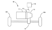
以下、本発明による自動変速装置の一実施形態を備えた車両について図面を参照して説明する。図1に示すように、車両Mは、エンジン11、クラッチ12、自動変速装置13、ディファレンシャル装置14、制御装置15、駆動輪(左右前輪)Wfl,Wfr等を含んで構成されている。
(1. Configuration of vehicle equipped with automatic transmission)
Hereinafter, a vehicle including an embodiment of an automatic transmission according to the present invention will be described with reference to the drawings. As shown in FIG. 1, the vehicle M includes an
エンジン11は、燃料の燃焼によって駆動力を発生させるものである。エンジン11の駆動力は、クラッチ12、自動変速装置13、およびディファレンシャル装置14を介して駆動輪Wfl,Wfrに伝達されるように構成されている(いわゆるFF車両である)。
クラッチ12は、制御装置15の指令に応じて自動で断接されるように構成されている。
自動変速装置13は、例えば前進6段、後進1段を自動的に選択するものである。
ディファレンシャル装置14は、ファイナルギヤおよびディファレンシャルギヤの両方を含んで構成されており、自動変速装置13と一体的に形成されている。
The
The
The
The
(2.自動変速装置の構成)
図2に示すように、自動変速装置13は、ケーシング21、ドライブシャフト22、メーンシャフト23、カウンタシャフト24、ドグクラッチ変速機構251,252,253,254および制御装置15に設けられている変速制御装置26等を含んで構成されている。
ケーシング21は、ほぼ円筒状に形成された本体21a、本体21a内を左右方向に区画する第1壁21bおよび第2壁21c等で構成されている。
(2. Configuration of automatic transmission)
As shown in FIG. 2, the
The
ドライブシャフト22およびメーンシャフト23は、同軸で配置され、カウンタシャフト24は、ドライブシャフト22およびメーンシャフト23に平行に配置されている。ドライブシャフト22、メーンシャフト23およびカウンタシャフト24は、ケーシング21に回転可能に支承されている。
すなわち、ドライブシャフト22の一端(左端)は、クラッチ12を介してエンジン11の出力軸に回転連結され、ドライブシャフト22の他端(右端)側は、軸受271を介して第1壁21bに支承されている。よって、エンジン11の出力はクラッチ12が接続されているときにドライブシャフト22に入力される。
The
That is, one end (left end) of the
メーンシャフト23の一端(左端)は、後述するドグクラッチ変速機構251を介してドライブシャフト22の一端(右端)に回転連結可能に軸支され、メーンシャフト23の他端(右端)側は、軸受272を介して第2壁21cに支承されている。メーンシャフト23が本願発明の回転軸である。なお、カウンタシャフト24を本願発明の回転軸としてもよい。
カウンタシャフト24の一端(左端)側は、軸受273を介して第1壁21bに支承され、カウンタシャフト24の他端(右端)側は、軸受274を介して第2壁21cに支承されている。
One end (left end) of the
One end (left end) side of the
そして、メーンシャフト23には、クラッチ側から順に、5速又はリバースに変速するドグクラッチ変速機構251、2速又は1速に変速するドグクラッチ変速機構252が配置され、カウンタシャフト24には、クラッチ側から順に、4速又は3速に変速するドグクラッチ変速機構253、6速に変速するドグクラッチ変速機構254が配置されている。各ドグクラッチ変速機構251,252,253,254は、後述する各速のギヤ281,282,283,284,285,286,28Rを備えている。
The
ドライブシャフト22の他端(右端)には、5速ギヤ285の回転中心がスプライン嵌合等で固定されている。メーンシャフト23には、クラッチ12側から順に、リバースギヤ28Rが回転自在に支承され、4速ギヤ284の回転中心がスプライン嵌合等で固定され、3速ギヤ283の回転中心がスプライン嵌合等で固定され、2速ギヤ282が回転自在に支承され、1速ギヤ281が回転自在に支承され、6速ギヤ286の回転中心がスプライン嵌合等で固定されている。
The rotation center of the
カウンタシャフト24には、5速ギヤ285に噛み合う第5カウンタギヤ295の回転中心がスプライン嵌合等で固定され、リバースギヤ28Rと1つのギヤ29rを介して噛み合う第2カウンタギヤ29Rの回転中心がスプライン嵌合等で固定され、4速ギヤ284に噛み合う第4カウンタギヤ294が回転自在に支承され、3速ギヤ283に噛み合う第3カウンタギヤ293が回転自在に支承され、2速ギヤ282に噛み合う第2カウンタギヤ292の回転中心がスプライン嵌合等で固定され、1速ギヤ281に噛み合う第1カウンタギヤ291の回転中心がスプライン嵌合等で固定され、6速ギヤ286に噛み合う第6カウンタギヤ296が回転自在に支承されている。1速ギヤ281および第1カウンタギヤ291の各外周面には、互いに噛合するギヤ(ヘリカルギヤ)が形成されている。他の互いに噛合するギヤにおいても同様である。
The rotation center of the fifth counter gear 295 that meshes with the
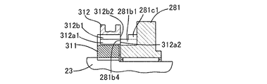
図3に示すように、ドグクラッチ変速機構252は、1速ギヤ(第1クラッチリング)281、2速ギヤ(第2クラッチリング)282、クラッチハブ(ハブ)311、スリーブ312、軸動装置313、位置検出センサ314等を含んで構成されている。ドグクラッチ変速機構253は、第3カウンタギヤ(第1クラッチリング)293、第4カウンタギヤ(第2クラッチリング)294、クラッチハブ(ハブ)321、スリーブ322、軸動装置323、位置検出センサ324等を含んで構成されている。他のドグクラッチ変速機構251も同様である。ただし、ドグクラッチ変速機構254は、第2クラッチリングは備えておらず、第1クラッチリングとして6速ギヤ286のみを備えている。以下では、ドグクラッチ変速機構252の詳細な構成について説明する。
As shown in FIG. 3, the dog
クラッチハブ311は、1速ギヤ281と2速ギヤ282との間にこれらと隣接してスプライン嵌合等で固定されている。
1速ギヤ281のクラッチハブ311側の側面には、スリーブ312に形成されているスプライン312a(図4参照)に係合する第1ドグクラッチ部281aが形成されている。同様に、2速ギヤ282のクラッチハブ311側の側面には、スリーブ312のスプライン312aに係合する第2ドグクラッチ部282aが形成されている。ここで、1速ギヤ281の第1ドグクラッチ部281aは、2速ギヤ282の第2ドグクラッチ部282aと同一構成であるため、図4〜図7には1速ギヤ281、クラッチハブ311およびスリーブ312を示して以下詳細に説明する。
The
A first dog
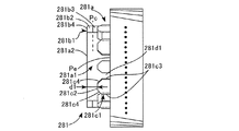
図4および図5A,Bに示すように、第1ドグクラッチ部281aには、リング状の凸部281a1と、凸部281a1の外周において180度隔てて配置された2枚のクラッチ前歯281b1と、凸部281a1の外周において2枚のクラッチ前歯281b1の間に5枚ずつ等角度間隔で配置されたクラッチ後歯281c1とが形成されている。クラッチ前歯281b1およびクラッチ後歯281c1は、凸部281a1の外周に一定幅のクラッチ歯溝281d1を空けて形成されている。
As shown in FIGS. 4 and 5A and 5B, the first dog
凸部281a1は、外径がスリーブ312に形成されているスプライン312aの高歯312a1の内径より小さくなるように形成されている。クラッチ前歯281b1は、外径がスプライン312aの高歯312a1の内径より大きく、スプライン312aの低歯312b1の内径より小さくなるように形成されている。クラッチ後歯281c1は、スプライン312aのスプライン歯溝312c1と噛合可能に形成されている。すなわち、クラッチ前歯281b1は、低歯312b1とは噛み合わず、高歯312a1と噛み合い可能に形成されている。クラッチ後歯281c1は、高歯312a1および低歯312b1と噛み合い可能に形成されている。
The
クラッチ前歯281b1は、高歯312a1と同数枚(本例では、2枚)形成されている。スリーブ312の回転速度と1速ギヤ281の回転速度に大きな差が生じていても、2枚の高歯312a1が2枚のクラッチ前歯281b1間に容易に入り込めるように、クラッチ前歯281b1は少歯とされている。そして、クラッチ前歯281b1は、高歯312a1と対応する位置で凸部281a1の前端面281a2からドグクラッチ部281aの後端位置Peまで延在して形成されている。クラッチ後歯281c1は、凸部281a1の前端面281a2から第1所定量d1後退した位置からドグクラッチ部281aの後端位置Peまで延在して形成されている。
The same number of clutch front teeth 281b1 as the high teeth 312a1 (two in this example) are formed. Even if there is a large difference between the rotational speed of the
クラッチ前歯281b1の高歯312a1と対向する前端部には、高歯312a1と当接可能な接触面281b4が形成され、さらに当該接触面281b4の円周方向両側からドグクラッチ部281aの後端位置Pe側に向かって傾斜する傾斜面281b2が形成されている。クラッチ前歯281b1の接触面281b4は、凸部281a1の前端面281a2と面一もしくは平行な平面状に形成されている。
A contact surface 281b4 that can contact the high teeth 312a1 is formed at the front end portion of the clutch front teeth 281b1 that faces the high teeth 312a1, and the dog
クラッチ後歯281c1には、高歯312a1および低歯312b1と当接可能な接触面281c2、並びに接触面281c2の円周方向両側から両側面281c3まで延びる側方傾斜面281c4が形成されている。クラッチ前歯281b1の傾斜面281b2がクラッチ前歯281b1の側面281b3と交差する位置Pcは、クラッチ後歯281c1の接触面281c2より凸部281a1の前端面281a2側となるように、クラッチ前歯281b1の傾斜面281b2は形成されている。なお、クラッチ前歯281b1の前端部の接触面281b4と両傾斜面281b2の交差部は、一般的な丸み面取り(R形状)に形成されている。 The clutch rear teeth 281c1 are formed with a contact surface 281c2 capable of contacting the high teeth 312a1 and the low teeth 312b1, and side inclined surfaces 281c4 extending from both sides in the circumferential direction of the contact surface 281c2 to both side surfaces 281c3. The position Pc at which the inclined surface 281b2 of the clutch front tooth 281b1 intersects the side surface 281b3 of the clutch front tooth 281b1 is closer to the front end surface 281a2 side of the convex portion 281a1 than the contact surface 281c2 of the clutch rear tooth 281c1. Is formed. The intersection of the contact surface 281b4 at the front end of the clutch front teeth 281b1 and both inclined surfaces 281b2 is formed in a general round chamfer (R shape).
図4および図6に示すように、クラッチハブ311の外周面には、スリーブ312の内周面に形成されているスプライン312aにメーンシャフト23の軸線方向に摺動可能に係合するスプライン311aが形成されている。スプライン311aは、複数(例えば2つ)の溝311a1が残りの溝より深く形成されている。複数の溝311a1は、スリーブ312の複数の高歯312a1に対応するものである。
As shown in FIGS. 4 and 6, a
図4および図7に示すように、スリーブ312は、クラッチハブ311と一体回転するとともにクラッチハブ311に対して軸線方向に摺動可能であり、リング状に形成されたものである。スリーブ312の内周面には、クラッチハブ311の外周面に形成されているスプライン311aに軸線方向に摺動可能に係合するスプライン312aが形成されている。
As shown in FIGS. 4 and 7, the
スプライン312aは、複数(例えば2つ)の高歯312a1が残りの低歯312b1より歯丈が高く形成されている。高歯312a1および低歯312b1における1速ギヤ281側の前端面の両端角部は、クラッチ前歯281b1やクラッチ後歯281c1と当接したときに衝撃で破損しないように、一般的な45度面取り(C形状)に形成されている。また、スリーブ312の外周面には、周方向に沿って外周溝312dが形成されている。外周溝312dには、フォーク313aの先端円弧部が周方向に沿って摺動可能に係合する。
In the
図3に示すように、軸動装置313は、スリーブ312を軸線方向に沿って往復動させるものであり、スリーブ312を1速ギヤ281または2速ギヤ282に押圧させている際に、1速ギヤ281または2速ギヤ282から反力が加わった場合に、スリーブ312がその反力によって移動することを許容するように構成されている。軸動装置323も同様である。
As shown in FIG. 3, the
軸動装置313は、フォーク313a、フォークシャフト313b、ディテント機構313cおよびリニアアクチュエータ313d等を含んで構成されている。軸動装置323も同様に、フォーク323a、フォークシャフト323b、ディテント機構323cおよびリニアアクチュエータ323d等を含んで構成されている。以下では、軸動装置313について説明する。
The
フォーク313aの先端部は、スリーブ312の外周溝312bの外周形状にあわせて形成されている。フォーク313aの基端部は、フォークシャフト313bに固定されている。
フォークシャフト313bは、ケーシング21に軸線方向に沿って摺動自在に支承されている。すなわち、フォークシャフト313bの一端(右端)が軸受313eを介して第2壁21cに支承され、フォークシャフト313bの他端(左端)側がブラケット313fに固定され、ブラケット313fは第1壁21bより軸線方向に突出するガイド部材(回り止め)313gによって摺動可能であるとともに、ナット部材313hに相対回転不能に固定されている。ナット部材313hはリニアアクチュエータ313dを備えた駆動シャフト313iに進退可能に螺合されている。駆動シャフト313iは軸受313jを介して第1壁21bに支承されている。
The tip of the
The
ディテント機構313cは、フォークシャフト313bの軸線方向の摺動位置、すなわちスリーブ312の移動位置を位置決めする機構である。ディテント機構313cは、図略のバネでフォークシャフト313bの軸線に直角な方向に付勢されているストッパ313c1を備え、ストッパ313c1がフォークシャフト313bに設けられている三角溝s1,sn,s2にバネ力で嵌まり込むことにより、フォークシャフト313bの軸線方向の摺動位置を位置決め可能に構成されている。
The
なお、ストッパ313c1は、スリーブ312のスプライン312aおよび1速ギヤ281の第1ドグクラッチ部281aが係合したとき三角溝s1に嵌まり込み、スリーブ312が1速ギヤ281および2速ギヤ282の中間に設定されているニュートラル位置(中立位置)Na(図10参照)に位置したとき三角溝snに嵌まり込み、スリーブ312のスプライン312aおよび2速ギヤ282の第2ドグクラッチ部282aが係合したとき三角溝s2に嵌まり込むようになっている。
The stopper 313c1 is fitted into the triangular groove s1 when the
リニアアクチュエータ313dとしては、例えば、ボールねじ式のリニアアクチュエータがある。これは例えば、円筒状に形成され内周方向に複数のコイルをステータ(図略)として配設させたケーシングと、ステータに対して回転自在に設けられ該ステータと磁気的空隙を設けて対向する複数のN極磁石とS極磁石とが外周に交互に配設されたロータ(図略)と、ステータの回転軸線を中心にロータとともに一体回転する駆動シャフト313i(ボールねじ軸)と、駆動シャフト313iに螺合されるボールナットからなるナット部材313hとから構成される。
An example of the
駆動シャフト313iはナット部材313hに複数のボール(図略)を介して相対回転可能に螺入されている。ステータの各コイルへの通電を制御することで、駆動シャフト313iが正逆双方向に任意に回転し、ナット部材313k及びフォークシャフト313bを往復動させるとともに、任意の位置に位置決め固定させる。また、このリニアアクチュエータ313dは、駆動シャフト313iのリードを長く形成することで、1速ギヤ281または2速ギヤ282から反力が加わった場合に、スリーブ312がその反力によって移動することを許容するように構成されている。これにより、スリーブ312のスプライン312aおよび2速ギヤ282の第2ドグクラッチ部282aの係合を確実に行うことができる。
The
なお、本実施形態では、リニアアクチュエータ313dとしてボールねじ式リニアアクチュエータを採用したが、スリーブ312を1速ギヤ281または2速ギヤ282に押圧させている際に、1速ギヤ281または2速ギヤ282から反力が加わった場合に、スリーブ312がその反力によって移動することを許容するように構成されているものであれば、他の駆動装置であるソレノイド式駆動装置や油圧式駆動装置でもよい。
位置検出センサ314は、スリーブ312が移動するときの位置を検出するセンサであり、例えば光位置センサやリニアエンコーダ等の各種位置センサを使用する。
In this embodiment, a ball screw type linear actuator is adopted as the
The
(3.ドグクラッチ変速機構の作動)
次に、ドグクラッチ変速機構252におけるスリーブ312の高歯312a1および低歯312b1、並びに1速ギヤ281のクラッチ前歯281b1およびクラッチ後歯281c1の作動について、図8A〜Dおよび図9A〜Dを参照して説明する。ここで、例えば、スリーブ312が2速ギヤ282と噛み合って高速で回転し、1速ギヤ281が低速で回転している場合、スリーブ312をシフトさせて1速ギヤ281と噛み合わせるとスリーブ312は減速される。一方、スリーブ312が1速ギヤ281と噛み合って低速で回転し、2速ギヤ282が高速で回転している場合、スリーブ312をシフトさせて2速ギヤ282と噛み合わせるとスリーブ312は増速される。以下の説明では減速動作を説明する。
(3. Actuation of dog clutch transmission mechanism)
Next, the operation of the high teeth 312a1 and low teeth 312b1 of the
図8Aに示すように、自動変速装置13のシフト前においては、スリーブ312は、1速ギヤ281から離間している。そして、スリーブ312が、軸動装置313により軸線方向に沿って1速ギヤ281側に移動されると、図8Bおよび図9Aに示すように、高歯312a1の前端面312a2が、クラッチ前歯281b1の接触面281b4と当接する。このとき、低歯312b1は、何にも当接していない。これにより、多少ではあるが、スリーブ312は、減速される。
As shown in FIG. 8A, the
さらに、スリーブ312が、軸動装置313により軸線方向に沿って移動されると、図9Bに示すように、高歯312a1の前端面312a2(面取り部)が、クラッチ前歯281b1の傾斜面281b2と当接する。このとき、低歯312b1は、何にも当接していない。これにより、スリーブ312は、大きく減速される。
Further, when the
さらに、スリーブ26が、軸動装置313により軸線方向に沿って移動されると、図8Cおよび図9Cに示すように、高歯312a1の前端面312a2および低歯312b1の前端面312b2が、クラッチ後歯281c1の接触面281c2と当接する。これにより、多少ではあるが、スリーブ312は、減速される。
Further, when the
さらに、スリーブ312が、軸動装置313により軸線方向に沿って移動されると、高歯312a1の前端面312a2(面取り部)および低歯312b1の前端面312b2(面取り部)が、クラッチ後歯281c1の側方傾斜面281c4と当接する。クラッチ前歯281b1およびクラッチ後歯281c1は、凸部281a1の外周に一定幅のクラッチ歯溝281d1を空けて形成されているので、高歯281a1および低歯281b1は、短時間で最寄りのクラッチ歯溝281d1に飛び込むことができる。これにより、スリーブ312は、大きく減速される。
Further, when the
さらに、スリーブ312が、軸動装置313により軸線方向に沿って移動されると、図8Dおよび図9Dに示すように、高歯312a1および低歯312b1は、クラッチ後歯281c1と完全に噛み合い、スリーブ312と1速ギヤ281とは同期回転し、シフト動作が完了する。
Further, when the
(4.変速制御装置の制御動作)
次に、変速制御装置26により、2速から3速に変速する場合の制御動作について説明する。図10Aに示すように、変速制御装置26は、軸動装置313を制御し、2速ギヤ282に係合していたスリーブ312を、1速ギヤ281および2速ギヤ282間に設定されているニュートラル位置Naに移動させて停止させる。そして、図10Bに示すように、軸動装置323を制御し、第3カウンタギヤ293および第4カウンタギヤ294間に設定されているニュートラル位置Nbに停止していたスリーブ322を、第3カウンタギヤ293に向かって移動させ第3カウンタギヤ293に係合させる。
(4. Control action of transmission control device)
Next, the control operation when shifting from the second speed to the third speed by the
ここで、本実施形態の自動変速装置13では、1速ギヤ281および2速ギヤ282の間隔、並びに第3カウンタギヤ293および第4カウンタギヤ294の間隔を狭くすることにより、変速時間の短縮化を図っている。しかし、例えば機構にガタが有る場合、スリーブ312がニュートラル位置Naにおいて停止したとき、スリーブ312が軸線方向に振れて1速ギヤ281に接触するおそれがある。スリーブが1速ギヤ281に接触すると、1速ギヤ281の回転数が高いときは、変速ショックや接触音が発生するという問題がある。
Here, in the
そこで、図11に示すように、本実施形態の変速制御装置26では、スリーブ312が係合していた2速ギヤ282とニュートラル位置Naとの間に目標位置Paを設定する。この目標位置Paは、スリーブ312および2速ギヤ282の係合が解除され、且つスリーブ312が目標位置Paに達したとき、スリーブ312が軸線方向に振れても1速ギヤ281に接触せず、ニュートラル位置Naに近い位置に設定される。これにより、スリーブ312の移動速度を高めて目標位置Paまで移動させることが可能となる。そして、目標位置Paからニュートラル位置Naまでは、スリーブ312が軸線方向に振れても1速ギヤ281に接触しない移動速度でスリーブを移動させる。すなわち、目標位置Paまでのスリーブ312の移動速度Vaが、目標位置Paからニュートラル位置Naまでのスリーブ312の移動速度Vbよりも速くなるように制御する。これにより、変速時間の短縮化を図ることができる。
Therefore, as shown in FIG. 11, in the speed
(5.変速制御装置の構成)
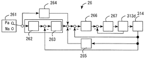
図12に示すように、変速制御装置26は、位置設定部261と、ローパスフィルタ部262と、I制御部263と、FF制御部264と、PD制御部265と、P制御部266と、PI制御部267とを備えて構成されている。この変速制御装置26は、周知のPID制御およびフィードフォワード制御により、スリーブ312の位置から制御電流を生成してリニアアクチュエータ313dに供給する。
位置設定部261は、目標位置Paおよびニュートラル位置Naを切り替えて設定する。
ローパスフィルタ部262は、位置設定部261で設定される目標位置Paおよびニュートラル位置Naまでスリーブ312を滑らかに移動させるためのスリーブ312の位置を指令する。
(5. Configuration of transmission control device)
As shown in FIG. 12, the
The
The low-
I制御部263は、ローパスフィルタ部262からの指令位置と、位置検出センサ324からの検出位置との偏差の積分に比例した制御を行うための制御指令値を演算する。
FF制御部264は、位置設定部261で設定される目標位置Paに基づいて、スリーブ312を速く移動させて目標位置Paに早く収束させるためのフィードフォワード指令値を出力する。FF制御部264は、初期フィードバック制御(図19の時点t1〜t3間の制御)の間、フィードフォワード指令値を出力する。このフィードフォワード指令値は、I制御部263で演算される制御指令値に加算される。
The I control
Based on the target position Pa set by the
PD制御部265は、位置検出センサ324からの検出位置の偏差を時間微分して求めた速度に基づいて制御を行うための制御指令値を演算する。この制御指令値は、I制御部263で演算される制御指令値から減算される。
P制御部266は、発散を防止するために、I制御部263、FF制御部264およびPD制御部265からの制御指令値と位置検出センサ324からの検出位置との偏差に比例した制御を行うための目標電流を演算する。
PI制御部267は、P制御部266からの目標電流と、リニアアクチュエータ313dからの検出電流との偏差および偏差の積分に応じて、実際の電流を目標電流と一致させる。
The
The
The
(6.変速制御装置の処理)
次に、変速制御装置26の処理について、図13から図18のフローチャートおよび図19のタイムチャートを参照して説明する。図13に示すように、変速制御装置26は、スリーブ312のニュートラル位置Naへの移動要求の有無を判断する(ステップS1)。そして、スリーブ312のニュートラル位置Naへの移動要求が有る場合、スリーブ312のスプライン312aおよび2速ギヤ282の第2ドグクラッチ部282aの係合解除制御を行う(ステップS2)。すなわち、図14に示すように、変速制御装置26は、リニアアクチュエータ313dに所定電流を供給する(ステップS21)。一方、ニュートラル位置Naへの移動要求が無い場合には、移動要求が有るまで待機する。
(6. Processing of transmission control device)
Next, the processing of the
すると、スリーブ312のスプライン312aおよび2速ギヤ282の第2ドグクラッチ部282aが係合している状態では、両者の静摩擦係数が大きいためスリーブ312は移動し難いが、図19に示すように、スリーブ312には、時点t0から所定電流Ia分の移動方向の推力が加えられるので、スリーブ312は徐々に移動してスリーブ312のスプライン312aが2速ギヤ282の第2ドグクラッチ部282aから抜け始める。
Then, when the
次に、図13に示すように、変速制御装置26は、スリーブ312が移動を開始したか否かを判断し(ステップS3)、スリーブ312が移動を開始したと判断したら、初期フィードバック制御を行う(ステップS4)。すなわち、図15に示すように、変速制御装置26は、目標位置Paを設定し(ステップS41)、ローパスフィルタ処理、すなわち目標位置Paまでスリーブ312を滑らかに移動させるためのスリーブ312の位置を指令する(ステップS42)。一方、スリーブ312が移動を開始したと判断しない場合には、ステップS2に戻る。
Next, as shown in FIG. 13, the speed
そして、スリーブ312の指令位置とスリーブ312の検出位置との偏差を演算し(ステップS43)、偏差の積分値を演算する(ステップS44)。そして、I制御部263は、偏差の積分値に積分ゲインを乗算して制御指令値IAを演算し(ステップS45)、PD制御部265は、偏差に比例ゲインを乗算して制御指令値IBを演算し(ステップS46)、偏差の時間変化に微分ゲインを乗算して制御指令値ICを演算する(ステップS47)。
Then, a deviation between the command position of the
そして、FF制御部264は、スリーブ312を速く移動させて目標位置Paに早く収束させるためのフィードフォワード指令値を目標位置Paに比例ゲインを乗算することにより求める(ステップS48)。そして、ステップS45で求めた制御指令値IAに、ステップS48で求めたフィードフォワード指令値IDを加算し、ステップS46で求めた制御指令値IBおよびステップS47で求めた制御指令値ICを減算してスリーブ312を移動させるためにリニアアクチュエータ313dに供給する最終的な制御電流IA−IB−IC+IDを演算する(ステップS49)。そして、リニアアクチュエータ313dの破壊防止のための電流値の上下限ガードを演算する(ステップS50)。
Then, the
すると、図19に示すように、リニアアクチュエータ313dには、フィードバック制御を開始する時点t1からt3の間においてフィードフォワード電流IDが供給される。
そして、時点t1から一旦減少した後に0に向かって増加する電流IA−IB−IC+IDが供給され、スリーブ312は目標位置Paに向かって比較的速い速度で移動する。このとき、変速制御装置26は、スリーブ312を図示実線で示すように滑らかに移動させるため、図示点線で示す指令位置でリニアアクチュエータ313dを制御する。
Then, as shown in FIG. 19, the feedforward current ID is supplied to the
Then, a current IA−IB−IC + ID that decreases once from time t1 and increases toward 0 is supplied, and the
そして、図19に示すように、スリーブ312のスプライン312aが、係合していた2速ギヤ282の第2ドグクラッチ部282aから離脱する前、すなわち、スリーブ位置が目標位置Paより前のPrに達する前(好ましくは直前)に、スリーブ312に移動方向とは逆方向の制動力を加える制御を行なっている。
Then, as shown in FIG. 19, before the
この制動力は、リニアアクチュエータ供給電流がゼロクロス点に達してゼロクロス点を越えたとき、すなわちスリーブ位置がPbに達してPbを越えたときから加えられる。フィードバック制御の開始時点t1からリニアアクチュエータ供給電流がゼロクロス点に至るまでは、スリーブ312のスプライン312aを2速ギヤ282の第2ドグクラッチ部282aから早く抜くためにリニアアクチュエータ供給電流を掛けるので、スリーブ312には制動力は掛からない。なお、PID制御のみでもスリーブ312に移動方向とは逆方向の制動力を加える制御を行なうことは可能である。
This braking force is applied when the linear actuator supply current reaches the zero cross point and exceeds the zero cross point, that is, when the sleeve position reaches Pb and exceeds Pb. From the feedback control start time t1 until the linear actuator supply current reaches the zero cross point, the
上述のフィードフォワード制御を行うことにより、スリーブ312を速く移動させて目標位置Paに早く収束させることができ、また、上述のPID制御を行うことにより、スリーブ312のスプライン312aが、係合していた2速ギヤ282の第2ドグクラッチ部282aから離脱する前に、スリーブ312に制動を掛けることができるので、目標位置Paにて迅速に停止させることができる。
By performing the feedforward control described above, the
次に、図13に示すように、変速制御装置26は、スリーブ312が目標位置Paに収束したか否かを判断(ステップS5)し、スリーブ312が目標位置Paに収束しない場合には前のステップS4に戻る。ステップS5にて、スリーブ312が目標位置Paに収束した場合には、図19に示すように、図示点線で示すスリーブ312の指令位置と図示実線で示すスリーブ312の実際の位置との差が所定値より小さくなり、且つ当該差が所定値より小さくなった時点t2から所定時間Tが経過した時点t3において、スリーブ312が目標位置Paに収束したと判断する。所定時間Tの経過を待っているので、目標位置Paに移動したスリーブ312の軸線方向の振れを減衰させることができ、目標位置Paからニュートラル位置Naまでのスリーブ312の移動速度を高めることができる。
Next, as shown in FIG. 13, the speed
ここで、変速制御装置26は、スリーブ312が目標位置Paに収束したと判断したら、スリーブ322のスプライン322aおよび第3カウンタギヤ293の第3ドグクラッチ部293aの係合制御を開始する。すなわち、図18に示すように、スリーブ312が目標位置Paに収束してスリーブ312のスプライン312aおよび2速ギヤ282の第2ドグクラッチ部292aの係合が解除されたと判断したら(ステップS91)、ニュートラル位置Nbに停止していたスリーブ322を第3カウンタギヤ293に向かって移動開始し、スリーブ322のスプライン322aおよび第3カウンタギヤ293の第3ドグクラッチ部293aを係合させる(ステップS92)。
Here, when the
一方、図13に示すように、変速制御装置26は、スリーブ312が目標位置Paに収束したと判断したら、終期フィードバック制御を行う(ステップS6)。すなわち、図16に示すように、変速制御装置26は、ニュートラル位置Naを設定し(ステップS61)、以下は図15に示すステップS42からS51までの処理のうち、フィードフォワード電流を求めて加算する処理(ステップS48およびステップS49のIDの加算)を除く処理を行う(ステップS62〜S69)。
On the other hand, as shown in FIG. 13, when the
すると、図19に示すように、リニアアクチュエータ313dには、時点t3から一旦増加した後に0に向かって減少する電流IA−IB−ICが供給され、スリーブ312はニュートラル位置Naに向かって比較的遅い速度、すなわち目標位置Paに向かう速度よりも遅い速度で移動する。このとき、変速制御装置26は、スリーブ312を図示実線で示すように滑らかに移動させるため、図示点線で示す指令位置でリニアアクチュエータ313dを制御する。
Then, as shown in FIG. 19, the
次に、図13に示すように、変速制御装置26は、スリーブ312がニュートラル位置Naに収束したか否かを判断する(ステップS7)。スリーブ312がニュートラル位置Naに収束しない場合には前のステップS6に戻る。ステップS7にて、スリーブ312がニュートラル位置Naに収束した場合には、図19に示すように、図示点線で示すスリーブ312の指令位置と図示実線で示すスリーブ312の実際の位置との差が所定値より小さくなった時点t4において、スリーブ312がニュートラル位置Naに収束したと判断する。
Next, as shown in FIG. 13, the
図13に示すように、変速制御装置26は、スリーブ312がニュートラル位置Naに収束したと判断したら、アイドル制御を行い(ステップS8)、全ての処理を終了する。すなわち、図17に示すように、変速制御装置26は、リニアアクチュエータ313dに供給する電流を0に設定する(ステップS81)。
As shown in FIG. 13, when the
(7.変速制御装置の他の処理)
上述の変速制御装置26の処理においては、図13のステップS5において、スリーブ312が目標位置Paに収束したか否かの判断は、スリーブ312の指令位置と実際の位置との差が所定値より小さくなり、且つ当該差が所定値より小さくなってから所定時間Tが経過した時点t3で行っている場合を説明した。しかし、スリーブ312の指令位置と実際の位置との差が所定値より小さくなった時点で、すなわち所定時間Tの経過を待たずに直ちにスリーブ312が目標位置Paに収束したと判断し、終期フィードバック制御を開始するようにしてもよい。この場合も、目標位置Paまでのスリーブ312の移動速度が、目標位置Paからニュートラル位置Naまでのスリーブ312の移動速度よりも速くなるように制御する。
(7. Other processing of shift control device)
In the above-described processing of the speed
また、上述の処理では、時点t1において、リニアアクチュエータ313dに所定電流IDを供給するフィードフォワード制御を行っているので、時点t1からt2において、ローパスフィルタ処理の時定数を大きくすることができる。一方、変速時間は若干長くなるが、時点t1からt2において、ローパスフィルタ処理の時定数を小さくすることにより、フィードフォワード制御を省略してフィードバック制御のみ行うようにしてもよい。
In the above-described processing, the feedforward control for supplying the predetermined current ID to the
13:自動変速装置、 23:メーンシャフト、 252,253:ドグクラッチ変速機構、 26:変速制御装置、 281:1速ギヤ(第1クラッチリング)、 282:2速ギヤ(第2クラッチリング)、 283:3速ギヤ、 284:4速ギヤ、 293:第3カウンタギヤ(第1クラッチリング)、 294:第4カウンタギヤ(第2クラッチリング)、 311,321:クラッチハブ(ハブ)、 312,322:スリーブ、 313,323:軸動装置、 314,324:位置検出センサ、 313d、323d:リニアアクチュエータ 13: Automatic transmission, 23: Main shaft, 252 and 253: Dog clutch transmission mechanism, 26: Transmission control device, 281: 1st gear (first clutch ring), 282: 2nd gear (second clutch ring), 283 : 3rd gear, 284: 4th gear, 293: 3rd counter gear (first clutch ring), 294: 4th counter gear (second clutch ring), 311, 321: Clutch hub (hub), 312, 322 : Sleeve, 313, 323: axial movement device, 314, 324: position detection sensor, 313d, 323d: linear actuator
Claims (3)
前記回転軸に回転可能に支承され前記入力軸および出力軸の他方に第1ギヤ比で回転連結された第1クラッチリングおよび第2ギヤ比で回転連結された第2クラッチリング、前記回転軸における前記第1および第2クラッチリングの間にこれらと隣接して固定されたハブ、前記ハブと相対回転が規制され前記軸線方向に移動可能に嵌合されたスリーブ、前記第1および第2クラッチリングの前記スリーブ側にそれぞれ突出して設けられ前記スリーブの軸動に応じて前記スリーブに形成されたスプラインとそれぞれ係脱可能に噛合する第1および第2ドグクラッチ部、前記スリーブを前記軸線方向に移動させる軸動装置、並びに前記スリーブの前記軸線方向の移動位置を検出するセンサを備えるドグクラッチ変速機構と、
前記センサの検出位置に基づいて、前記軸動装置の作動を制御する制御装置と、を備え、
前記制御装置は、前記第1および第2クラッチリングの一方と係合した状態の前記スリーブを移動させるために、前記軸動装置に所定の電流を供給し、前記スリーブのスプラインが前記係合していたクラッチリングのドグクラッチ部から離脱する前に、前記スリーブに移動方向とは逆方向の制動力を加えるために、前記軸動装置に前記所定電流より小さい制動電流を供給する自動変速装置。 A rotary shaft that is rotatably connected to one of the input shaft and the output shaft of the automatic transmission and is rotatably supported about the axis;
A first clutch ring rotatably supported on the rotary shaft and rotationally connected to the other of the input shaft and the output shaft at a first gear ratio, and a second clutch ring rotationally connected to the second gear ratio; A hub fixed adjacent to and between the first and second clutch rings, a sleeve which is relatively fitted with the hub and whose relative rotation is restricted, and is movably fitted in the axial direction; the first and second clutch rings The first and second dog clutch portions that protrude from the sleeve side and engage with the splines formed in the sleeve according to the axial movement of the sleeve, respectively, and move the sleeve in the axial direction. A dog clutch transmission mechanism comprising an axial movement device and a sensor that detects a movement position of the sleeve in the axial direction;
A control device for controlling the operation of the axial movement device based on the detection position of the sensor,
The control device supplies a predetermined current to the axial movement device to move the sleeve engaged with one of the first and second clutch rings, and the spline of the sleeve engages the engagement. An automatic transmission that supplies a braking current smaller than the predetermined current to the shaft driving device in order to apply a braking force in a direction opposite to a moving direction to the sleeve before the clutch ring is disengaged from the dog clutch portion.
Priority Applications (4)
| Application Number | Priority Date | Filing Date | Title |
|---|---|---|---|
| JP2013017263A JP2014149021A (en) | 2013-01-31 | 2013-01-31 | Automatic transmission device |
| US14/151,104 US8914209B2 (en) | 2013-01-31 | 2014-01-09 | Automatic shift apparatus |
| EP14151184.0A EP2762756A3 (en) | 2013-01-31 | 2014-01-14 | Automatic shift apparatus |
| CN201410043813.9A CN103968065A (en) | 2013-01-31 | 2014-01-29 | Automatic shift apparatus |
Applications Claiming Priority (1)
| Application Number | Priority Date | Filing Date | Title |
|---|---|---|---|
| JP2013017263A JP2014149021A (en) | 2013-01-31 | 2013-01-31 | Automatic transmission device |
Publications (1)
| Publication Number | Publication Date |
|---|---|
| JP2014149021A true JP2014149021A (en) | 2014-08-21 |
Family
ID=49918633
Family Applications (1)
| Application Number | Title | Priority Date | Filing Date |
|---|---|---|---|
| JP2013017263A Pending JP2014149021A (en) | 2013-01-31 | 2013-01-31 | Automatic transmission device |
Country Status (4)
| Country | Link |
|---|---|
| US (1) | US8914209B2 (en) |
| EP (1) | EP2762756A3 (en) |
| JP (1) | JP2014149021A (en) |
| CN (1) | CN103968065A (en) |
Cited By (2)
| Publication number | Priority date | Publication date | Assignee | Title |
|---|---|---|---|---|
| JP2018168880A (en) * | 2017-03-29 | 2018-11-01 | シンフォニアテクノロジー株式会社 | Lock control device for drive gear, and lock control device for actuator |
| US11808348B2 (en) | 2019-10-29 | 2023-11-07 | Indian Motorcycle International, LLC | Reverse gear system for vehicle |
Families Citing this family (9)
| Publication number | Priority date | Publication date | Assignee | Title |
|---|---|---|---|---|
| JP2014149019A (en) * | 2013-01-31 | 2014-08-21 | Aisin Seiki Co Ltd | Automatic transmission device |
| US10030963B2 (en) * | 2015-10-01 | 2018-07-24 | Raytheon Company | Multidimensional angle determination using fine position sensors |
| US10557535B2 (en) * | 2016-06-01 | 2020-02-11 | Earl Stuart Douglass | Reversible continuously spinning transmission for electric motors |
| US9689437B1 (en) * | 2016-06-23 | 2017-06-27 | Premier Coil Solutions, Inc. | Clutch mechanism |
| JP6926853B2 (en) * | 2017-09-06 | 2021-08-25 | 株式会社ジェイテクト | Driving force transmission control device |
| JPWO2020196319A1 (en) * | 2019-03-22 | 2021-11-25 | 株式会社アイシン | Vehicle drive and control |
| JP7392489B2 (en) * | 2020-01-20 | 2023-12-06 | 株式会社ジェイテクト | Driving force transmission control device and method of controlling the driving force transmission device |
| US11493096B2 (en) * | 2020-11-13 | 2022-11-08 | Schaeffer Technologies AG & Co. KG | Axle disconnect assembly |
| CN114321198A (en) * | 2021-12-21 | 2022-04-12 | 清华大学苏州汽车研究院(吴江) | Gear rack type dog clutch mechanism |
Family Cites Families (6)
| Publication number | Priority date | Publication date | Assignee | Title |
|---|---|---|---|---|
| US5086670A (en) * | 1991-07-31 | 1992-02-11 | Saturn Corporation | Adaptive transmission shift pressure control with closed-loop compensation |
| JP4622053B2 (en) * | 2000-06-29 | 2011-02-02 | いすゞ自動車株式会社 | Shift assist device for transmission |
| US7949450B2 (en) * | 2007-11-09 | 2011-05-24 | GM Global Technology Operations LLC | Control system for a torque transmitting device in an automatic transmission |
| JP2011047511A (en) * | 2009-08-28 | 2011-03-10 | Yamaha Motor Co Ltd | Multiple clutch transmission control apparatus and multiple clutch transmission control method |
| JP5649360B2 (en) * | 2010-08-02 | 2015-01-07 | アイシン・エーアイ株式会社 | Vehicle power transmission control device |
| JP5197791B2 (en) | 2011-04-20 | 2013-05-15 | ヤマハ発動機株式会社 | Transmission and straddle-type vehicle |
-
2013
- 2013-01-31 JP JP2013017263A patent/JP2014149021A/en active Pending
-
2014
- 2014-01-09 US US14/151,104 patent/US8914209B2/en not_active Expired - Fee Related
- 2014-01-14 EP EP14151184.0A patent/EP2762756A3/en not_active Withdrawn
- 2014-01-29 CN CN201410043813.9A patent/CN103968065A/en active Pending
Cited By (3)
| Publication number | Priority date | Publication date | Assignee | Title |
|---|---|---|---|---|
| JP2018168880A (en) * | 2017-03-29 | 2018-11-01 | シンフォニアテクノロジー株式会社 | Lock control device for drive gear, and lock control device for actuator |
| US11808348B2 (en) | 2019-10-29 | 2023-11-07 | Indian Motorcycle International, LLC | Reverse gear system for vehicle |
| JP7422221B2 (en) | 2019-10-29 | 2024-01-25 | インディアン・モーターサイクル・インターナショナル・エルエルシー | Vehicle back gear system |
Also Published As
| Publication number | Publication date |
|---|---|
| CN103968065A (en) | 2014-08-06 |
| EP2762756A3 (en) | 2016-05-04 |
| US20140214294A1 (en) | 2014-07-31 |
| US8914209B2 (en) | 2014-12-16 |
| EP2762756A2 (en) | 2014-08-06 |
Similar Documents
| Publication | Publication Date | Title |
|---|---|---|
| JP2014149021A (en) | Automatic transmission device | |
| JP6212893B2 (en) | Dog clutch control device for automatic transmission | |
| JP5994820B2 (en) | Meshing engagement device | |
| JP2013217491A (en) | Dog clutch for automated transmission | |
| JP2014149022A (en) | Dog clutch control device for automatic transmission | |
| JP6186789B2 (en) | Automatic transmission for automatic transmission for vehicle | |
| JP6205853B2 (en) | Dog clutch control device for automatic transmission | |
| JP2014149019A (en) | Automatic transmission device | |
| JP2013217490A (en) | Dog clutch for automated transmission | |
| JP2014149020A (en) | Dog clutch control device for automatic transmission | |
| JP6236965B2 (en) | Dog clutch control device for automatic transmission | |
| JP6438292B2 (en) | Vehicle transmission | |
| JP2014098459A (en) | Dog clutch for automatic transmission | |
| JP2015064080A (en) | Automatic shift device and automatic shift method | |
| JP3970864B2 (en) | Contact mechanism control device | |
| JP2015224715A (en) | Automatic transmission | |
| JP6070380B2 (en) | Automatic transmission for automatic transmission for vehicle | |
| JP5994303B2 (en) | Automatic transmission with dog clutch | |
| JP6065691B2 (en) | Shift detent device | |
| JP2015086937A (en) | Dog clutch control device of automatic transmission | |
| JP2015140851A (en) | Dog clutch device for automatic transmission | |
| JP6561335B2 (en) | Automatic transmission | |
| JP6459715B2 (en) | Dog clutch control system | |
| JP2015081618A (en) | Dog clutch type transmission device | |
| JP6298997B2 (en) | Automatic transmission |