JP2014148202A - Lighting fixture for vehicle - Google Patents
Lighting fixture for vehicle Download PDFInfo
- Publication number
- JP2014148202A JP2014148202A JP2013016842A JP2013016842A JP2014148202A JP 2014148202 A JP2014148202 A JP 2014148202A JP 2013016842 A JP2013016842 A JP 2013016842A JP 2013016842 A JP2013016842 A JP 2013016842A JP 2014148202 A JP2014148202 A JP 2014148202A
- Authority
- JP
- Japan
- Prior art keywords
- vehicle
- light distribution
- distribution pattern
- road surface
- lamp
- Prior art date
- Legal status (The legal status is an assumption and is not a legal conclusion. Google has not performed a legal analysis and makes no representation as to the accuracy of the status listed.)
- Pending
Links
Images


Abstract
Description
本発明は、特に夜間に、車両を目標物に対して車幅方向にずれることなく後退させることができるようにした車両用灯具に関する。 The present invention relates to a vehicular lamp that can retreat a vehicle without shifting in the vehicle width direction with respect to a target, particularly at night.
車両後端部に配設されたバックランプあるいはブレーキランプ等の車両用灯具として、従来、例えば特許文献1に開示されたものがある。この従来のバックランプやブレーキランプは、該ランプからの光を、車両後端から所定距離だけ離れた路面上にて、車幅方向に平行な配光パターンをなすよう照射するように構成されている。そして車両後退時に、前記配光パターンを、バックドアウインドを通して、あるいはリヤアンダーミラーを介して目視しつつ、車両後端に平行な目標物、例えば駐車枠の白線やポール間を結ぶ仮想直線に一致させることにより、車両を目標物との間に適正な距離を保った状態で駐車可能としている。
Conventionally, as a vehicular lamp such as a back lamp or a brake lamp disposed at the rear end portion of the vehicle, there is one disclosed in
前記従来の車両用灯具では、車両後端から所定距離だけ離れた路面上にて、車幅方向に平行な配光パターンを形成するようにしているので、該配光パターンを目標物に一致させることで車両の後端から目標物までの距離を適正に保つことができる。 In the conventional vehicular lamp, a light distribution pattern parallel to the vehicle width direction is formed on the road surface separated from the rear end of the vehicle by a predetermined distance, so that the light distribution pattern matches the target. Thus, the distance from the rear end of the vehicle to the target can be properly maintained.
しかし車幅に関しては後退時の目安となるものがなく、例えば夜間における縦列駐車等で車両を後退させて駐車する場合に、駐車枠を示す白線から幅方向にはみ出て駐車してしまう場合が懸念される。 However, there is no guideline for reversing the width of the vehicle, and there is a concern that the vehicle may be parked by protruding in the width direction from the white line indicating the parking frame when the vehicle is retracted and parked in parallel parking at night, for example. Is done.
本発明は、前記従来の状況に鑑みてなされたもので、車幅に関して目安となる配光パターンを設けることにより車両の後退支援を行うことができる車両用灯具を提供することを課題としている。 The present invention has been made in view of the above-described conventional situation, and it is an object of the present invention to provide a vehicular lamp that can assist the vehicle to move backward by providing a light distribution pattern that is a guide for the vehicle width.
請求項1の発明は、車両後端部かつ車幅方向外側部に取り付けられた車両用灯具において、
前記灯具は、光を、路面上にて、車両長手方向に平行な直線状の配光パターンをなすように照射することを特徴としている。
The invention of
The lamp is characterized by irradiating light on a road surface so as to form a linear light distribution pattern parallel to the longitudinal direction of the vehicle.
請求項2の発明は、請求項1に記載の車両用灯具において、
前記配光パターンは、車両後端近傍の路面位置から後方に所定距離離れた路面位置までの第1領域内で直線状をなすように形成されることを特徴としている。
The invention of
The light distribution pattern is formed so as to form a straight line within a first region from a road surface position near the rear end of the vehicle to a road surface position spaced a predetermined distance backward.
請求項3の発明は、請求項1に記載の車両用灯具において、
前記配光パターンは、車両後端から後方に所定距離離れた路面位置からさらに後方の路面位置までの第2領域内で直線状をなすように形成されることを特徴としている。
The invention of
The light distribution pattern is formed so as to form a straight line in a second region from a road surface position a predetermined distance rearward from the rear end of the vehicle to a rear road surface position.
請求項1の発明によれば、車幅方向外側部に配置された灯具からの光を、路面に車両長手方向に平行な直線状の配光パターンをなすように照射したので、該配光パターンは、略車幅を表しており、運転者は、フロントドアウインドから顔を出して、又はサイドミラーを介して、あるいはバックドアウインドを通して、又は車両後端部に配設されたリヤアンダーミラーを介して前記配光パターンを目視することにより車幅を確認しつつ車両を後退させることができる。 According to the first aspect of the present invention, the light from the lamp disposed at the outer side in the vehicle width direction is irradiated so as to form a linear light distribution pattern parallel to the vehicle longitudinal direction on the road surface. Represents the approximate vehicle width, and the driver looks out from the front door window, through the side mirror, through the back door window, or the rear under mirror disposed at the rear end of the vehicle. The vehicle can be moved backward while confirming the vehicle width by visually checking the light distribution pattern.
従って運転者は、特に夜間の後退時に、車両を目標物に対して車幅方向にずらすことなく後退させることができ、例えば駐車枠を示す白線内に容易確実に駐車できる。 Accordingly, the driver can move the vehicle backward without shifting in the vehicle width direction with respect to the target, particularly when the vehicle moves backward at night. For example, the driver can easily and reliably park within the white line indicating the parking frame.
請求項2の発明では、配光パターンを、車両後端近傍の路面位置から後方に所定距離離れた路面位置までの第1領域内で直線状をなすように形成したので、この配光パターンの後端部が目標物に投射されたとき、車両後端部と目標物との距離が配光パターンの長さに略一致することとなり、これにより車両の前後方向の距離についても目安を得ることができ、車両後端部と目標物との間に適正な距離を保つことができる。
In the invention of
従って、前記第1領域の長さは、つまり車両後端近傍の路面位置から所定距離離れた路面位置までの距離は、後退して駐車する場合の、車両後端と目標物との間に確保すべき適正距離に設定されることとなる。 Therefore, the length of the first area, that is, the distance from the road surface position near the rear end of the vehicle to the road surface position that is a predetermined distance away, is ensured between the rear end of the vehicle and the target when the vehicle is parked backward. The appropriate distance to be set is set.
請求項3の発明では、配光パターンを、車両後端から後方に所定距離離れた路面位置からさらに後方の路面位置までの第2領域内で直線状をなすように形成したので、この配光パターンの前端部又は全体が目標物に投射されたとき、車両と目標物との距離が車両後端から配光パターン形成開始点までの距離に一致することとなり、これにより車両の前後方向の距離についても目安を得ることができ、車両後端部と目標物との間に適正な距離を保つことができる。
In the invention of
従って、前記第2領域の前端までの距離は、後退して駐車する場合の、車両後端と目標物との間に確保すべき適正距離に設定されることとなる。 Therefore, the distance to the front end of the second area is set to an appropriate distance that should be secured between the rear end of the vehicle and the target when the vehicle is parked backward.
以下、本発明の実施形態を添付図面に基づいて説明する。 Hereinafter, embodiments of the present invention will be described with reference to the accompanying drawings.
図1ないし図7は本発明の実施例1に係る車両用灯具を説明するための図であり、図中、前,後,左,右とは、車両前方に見た状態での前,後,左,右を意味している。 1 to 7 are diagrams for explaining a vehicular lamp according to a first embodiment of the present invention. In the drawings, front, rear, left, and right are front and rear when viewed in front of the vehicle. , Left and right.
図において、1は車両であり、該車両1の車体2の後端部にはドア開口2aが形成され、該ドア開口2aはバックドア3により開閉可能となっている。前記バックドア3は、ウインド開口3aを有し、該ウインド開口3aにはウインドシールド3bが配設されている。
In the figure,
前記バックドア3の前記ウインド開口3aの上枠部にはハイマウントストップランプ6が配設されている。このハイマウントストップランプ6は、反射面を有するランプケース6aと、該ランプケース6a内に配置されたLED光源6bと、前記ランプケース6aの開口の後方部分及び下方部分を覆うように配設されたレンズ6cと、前記光源6bからの光が前方に拡散するのを防止する隔壁7aを有する。なお、7cは前記光に車室内に拡散するのを防止するカバーである。
A high
前記ハイマウントストップランプ6の前方にはリヤアンダーミラー8が配設されている。このリヤアンダーミラー8は、支持ブラケット7に凹設されたミラーハウジング7d内に鏡面8aを有するミラー本体8bを配設した構造を有する。なお、前記隔壁7aは前記支持ブラケット7の基部7bに取付けられている。
A rear under
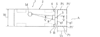
前記リヤアンダーミラー8の鏡面8aは、上下方向に凹状で、かつ水平方向に凸状をなしている。このリヤアンダーミラー8によって運転者は着座したまま後方を振り返って見ることにより車両後端部から後方の所定領域Aの状況を把握することができる。図5において、運転者Mの視線a1に対する反射ラインa1′は前記所定領域Aの最遠部に対応し、視線a2に対する反射ラインa2′は前記所定領域Aの最近部に対応している。なお、視線a2からa3に対する反射ラインa2′からa3′は自車が映される領域に対応している。
The
前記車体2のドア開口2aの下縁部にはリヤバンパ4が配設されている。このリヤバンパ4には、車幅方向最外側部に位置するように左,右のバックランプ5,5が配設されている。
A
前記バックランプ5は、反射面9aを有するランプケース9と、該ランプケース9内に配設された白熱電球からなる光源10と、前記ランプケース9の車両後方に向かって開口する後方開口9bを覆うように配設され、前記光源10から照射された、あるいは前記反射面9aで反射された光Rが透過するランプレンズ11とを有する。
The
前記光Rはレギュレーションを満たす光度,形状,サイズ等を有する基準配光パターンPを形成する。また前記ランプレンズ11には、前記光Rの一部が透過する際に本実施例の特徴をなす配光パターンP1をなすよう屈折させるレンズカット11aが形成されている。このレンズカット11aは、前記光Rの一部が該レンズカット11aを透過する際に、車両長手方向に平行な直線状の前記配光パターンP1をなすよう屈折するように、そのカット面の角度,形状,サイズ等が設定されている。
The light R forms a reference light distribution pattern P having a luminous intensity, shape, size, etc. that satisfies the regulation. The
ここで、前記配光パターンP1は、図1,図2に示すように、車両後端Bの近傍の路面位置g1から後方に所定距離(例えば1〜2m)離れた路面位置g2までの第1領域T1内で、車両長手方向に平行な直線状をなしている。従って配光パターンP1は概ね1〜2mの長さを有する。なお、各図において、配光パターンP1を白抜き太線の破線で表しているが、これは他のラインと明確に区別するためであって、実際は連続した直線状をなしている。 Here, as shown in FIGS. 1 and 2, the light distribution pattern P <b> 1 is the first from the road surface position g <b> 1 in the vicinity of the vehicle rear end B to the road surface position g <b> 2 separated by a predetermined distance (for example, 1 to 2 m). Within the region T1, it forms a straight line parallel to the longitudinal direction of the vehicle. Therefore, the light distribution pattern P1 has a length of approximately 1 to 2 m. In each figure, the light distribution pattern P1 is represented by a bold white broken line, but this is for clear distinction from the other lines, and is actually a continuous straight line.
なお、前記光を屈折させるには各種の方法が採用可能であり、前述のようにランプレンズ11にレンズカット11aを形成する方法の他、例えば前記反射面9aの形状により前記配光パターンP1を形成するようにしてもよい良い。
Various methods can be used to refract the light. In addition to the method of forming the lens cut 11a on the
本実施例1によれば、車幅方向外側部に配置されたバックランプ5,5からの光Rを、路面E上にて車両長手方向に平行な直線状の配光パターンP1,P1をなすように照射したので、該配光パターンP1,P1は、略車幅Wを表しており、運転者Mは、着座したまま後を振り返ることにより、図7に示すように、リヤアンダーミラー8を介して前記配光パターンP1,P1を目視することができ、車幅Wを確認しつつ車両1を後退させることができる。なお、図7において、配光パターンP1が湾曲しているが、これは反射面の形状に起因するものであって、実際は直線状をなしている。また同図中、12aは駐車枠の横幅を示す白線、12bは駐車枠の後端部を示すストッパであり、さらにまた3a′は前記バックドア3のウインド開口3aの下縁部、3cは該下縁部3a′に取り付けられたリヤワイパである。
According to the first embodiment, the light R from the
このようにして運転者Mは、特に夜間の後退時に、車両1を、前記配光パターンP1が白線(目標物)12aに沿うように後退させることにより、駐車枠に対して車幅方向にずらすことなく後退させることができ、駐車枠を示す白線12a,12a内に容易確実に駐車できる。
In this way, the driver M shifts the
また本実施例1では、配光パターンP1を、車両後端B近傍の路面位置g1から後方に所定距離離れた路面位置g2までの第1領域T1内で直線状をなすように形成したので、例えば、図1における壁Cが後退限界を示す目標物である場合は、前記配光パターンP1の後端部P1′が前記壁C等に投射開始されたとき、車両後端部Bと壁Cとの距離が配光パターンP1の長さに略一致することとなり、これにより車両1の前後方向の距離についても目安を得ることができ、車両1の後端部Bと壁Cとの間に適正な距離を保って駐車することができる。
In the first embodiment, the light distribution pattern P1 is formed so as to be linear in the first region T1 from the road surface position g1 in the vicinity of the rear end B of the vehicle to the road surface position g2 that is a predetermined distance behind. For example, when the wall C in FIG. 1 is a target indicating the retreat limit, when the rear end portion P1 ′ of the light distribution pattern P1 starts to be projected onto the wall C or the like, the vehicle rear end portion B and the wall C Is approximately equal to the length of the light distribution pattern P1, so that a guideline can be obtained for the distance in the front-rear direction of the
なお、ストッパ12bを有する駐車枠内に駐車する場合は、図7に示すように、配光パターンP1,P1がストッパ12b,12b上を通るように車両1を位置させた状態で、車輪がストッパ12bに当接するまで低速で後退すれば良い。
In addition, when parking in the parking frame which has the
図8及び図9は本発明の実施例2を説明するための図であり、図中、図1,図2と同一符号は同一又は相当部分を示す。 8 and 9 are diagrams for explaining a second embodiment of the present invention, in which the same reference numerals as those in FIGS. 1 and 2 indicate the same or corresponding parts.
本実施例2は、実施例1の配光パターンP1と異なる配光パターンP2を形成した例である。この配光パターンP2は、車両後端Bから後方に所定距(例えば1〜2m)離離れた路面位置g3からさらに1〜2m 後方の路面位置g4までの第2領域T2内で直線状をなすように形成されている。従って配光パターンP2は、車両後端Bから1〜2m離れた位置から後方に1〜2mの長さを有する。
The second embodiment is an example in which a light distribution pattern P2 different from the light distribution pattern P1 of the first embodiment is formed. This light distribution pattern P2 forms a straight line in the second region T2 from the road surface position g3 that is separated from the rear end B of the vehicle by a predetermined distance (for example, 1 to 2 m) to the road surface position g4 that is further 1 to 2 m behind. It is formed as follows. Accordingly, the light distribution pattern P2 has a length of 1 to 2 m rearward from a
このように本実施例2では、配光パターンP2を、車両後端Bから後方に所定距離離れた路面位置g3からさらに後方の路面位置g4までの第2領域T2内で直線状をなすように形成したので、例えば、壁Cが後退限界を示す目標物である場合は、前記配光パターンP2の全体が前記壁Cに投射されたとき、車両1と壁Cとの距離が車両後端Bから配光パターン形成開始点(路面位置g3)までの距離に一致することとなり、これにより車両1の前後方向の距離についても目安を得ることができ、車両1の後端部Bと壁Cとの間に適正な距離を保って駐車することができる。ストッパ12bを有する駐車枠内に駐車する場合は、前記実施例1の場合と同様である。
As described above, in the second embodiment, the light distribution pattern P2 is linearly formed in the second region T2 from the road surface position g3 that is a predetermined distance away from the vehicle rear end B to the rear road surface position g4. For example, when the wall C is a target indicating the retreat limit, when the entire light distribution pattern P2 is projected onto the wall C, the distance between the
なお、前記実施例1,2では、灯具がバックランプである場合を説明したが、本発明の灯具は、ブレーキランプあるいはテールランプであっても良い。 In the first and second embodiments, the case where the lamp is a back lamp has been described. However, the lamp of the present invention may be a brake lamp or a tail lamp.
また、前記実施例1,2では、車室内側に配設されたリヤアンダーミラー8に映された配光パターンを目視するようにしたが、勿論車室外側に配設されたリヤアンダーミラーを利用しても良く、さらに本発明は、リヤアンダーミラーを備えない車両の場合にも適用できる。例えば、配光パターンP1又はP2を、サイドミラーを介して又はフロントドアのウインド開口から顔を出して目視しても良く、さらにまたバックドアのウインド開口の形状の如何によっては該開口を通して前記配光パターンを目視しても良い。
In the first and second embodiments, the light distribution pattern projected on the rear under
5 バックランプ(灯具)
B 車両後端部
E 路面
g1〜g4 路面位置
P1,P2 配光パターン
R1,R2 光
T1 第1領域
T2 第2領域
5 Back lamp (lamp)
B Vehicle rear end E Road surface g1 to g4 Road surface position P1, P2 Light distribution pattern R1, R2 Light T1 First region T2 Second region
Claims (3)
前記灯具は、光を、路面上にて、車両長手方向に平行な直線状の配光パターンをなすように照射する
ことを特徴とする車両用灯具。 In the vehicular lamp attached to the rear end of the vehicle and the outer side in the vehicle width direction,
The said lamp irradiates light on the road surface so that the linear light distribution pattern parallel to a vehicle longitudinal direction may be made, The vehicle lamp characterized by the above-mentioned.
前記配光パターンは、車両後端近傍の路面位置から後方に所定距離離れた路面位置までの第1領域内で直線状をなすように形成される
ことを特徴とする車両用灯具。 The invention of claim 2 is the vehicle lamp according to claim 1,
The vehicular lamp according to claim 1, wherein the light distribution pattern is formed so as to form a straight line within a first region from a road surface position near the rear end of the vehicle to a road surface position spaced a predetermined distance backward.
前記配光パターンは、車両後端から後方に所定距離離れた路面位置からさらに後方の路面位置までの第2領域内で直線状をなすように形成される
ことを特徴とする車両用灯具。 The invention of claim 3 is the vehicle lamp according to claim 1 or 2,
The vehicular lamp according to claim 1, wherein the light distribution pattern is formed so as to form a straight line in a second region from a road surface position spaced a predetermined distance rearward from the rear end of the vehicle to a road surface position further rearward.
Priority Applications (1)
| Application Number | Priority Date | Filing Date | Title |
|---|---|---|---|
| JP2013016842A JP2014148202A (en) | 2013-01-31 | 2013-01-31 | Lighting fixture for vehicle |
Applications Claiming Priority (1)
| Application Number | Priority Date | Filing Date | Title |
|---|---|---|---|
| JP2013016842A JP2014148202A (en) | 2013-01-31 | 2013-01-31 | Lighting fixture for vehicle |
Publications (1)
| Publication Number | Publication Date |
|---|---|
| JP2014148202A true JP2014148202A (en) | 2014-08-21 |
Family
ID=51571569
Family Applications (1)
| Application Number | Title | Priority Date | Filing Date |
|---|---|---|---|
| JP2013016842A Pending JP2014148202A (en) | 2013-01-31 | 2013-01-31 | Lighting fixture for vehicle |
Country Status (1)
| Country | Link |
|---|---|
| JP (1) | JP2014148202A (en) |
Cited By (2)
| Publication number | Priority date | Publication date | Assignee | Title |
|---|---|---|---|---|
| CN104237895A (en) * | 2014-09-24 | 2014-12-24 | 奇瑞汽车股份有限公司 | Reversing warning system |
| WO2020001999A1 (en) | 2018-06-25 | 2020-01-02 | Volkswagen Aktiengesellschaft | Marking device, vehicle, and computer program |
Citations (3)
| Publication number | Priority date | Publication date | Assignee | Title |
|---|---|---|---|---|
| JP2003285685A (en) * | 2002-03-27 | 2003-10-07 | Toyota Motor Corp | Vehicle operation-supporting system |
| JP2009087584A (en) * | 2007-09-27 | 2009-04-23 | Kanto Auto Works Ltd | Prism lens and lighting device for vehicle with the same |
| JP2012025261A (en) * | 2010-07-22 | 2012-02-09 | Stanley Electric Co Ltd | Parking assist device |
-
2013
- 2013-01-31 JP JP2013016842A patent/JP2014148202A/en active Pending
Patent Citations (3)
| Publication number | Priority date | Publication date | Assignee | Title |
|---|---|---|---|---|
| JP2003285685A (en) * | 2002-03-27 | 2003-10-07 | Toyota Motor Corp | Vehicle operation-supporting system |
| JP2009087584A (en) * | 2007-09-27 | 2009-04-23 | Kanto Auto Works Ltd | Prism lens and lighting device for vehicle with the same |
| JP2012025261A (en) * | 2010-07-22 | 2012-02-09 | Stanley Electric Co Ltd | Parking assist device |
Cited By (3)
| Publication number | Priority date | Publication date | Assignee | Title |
|---|---|---|---|---|
| CN104237895A (en) * | 2014-09-24 | 2014-12-24 | 奇瑞汽车股份有限公司 | Reversing warning system |
| WO2020001999A1 (en) | 2018-06-25 | 2020-01-02 | Volkswagen Aktiengesellschaft | Marking device, vehicle, and computer program |
| DE102018210300A1 (en) | 2018-06-25 | 2020-01-02 | Volkswagen Aktiengesellschaft | Marking device, vehicle and computer program |
Similar Documents
| Publication | Publication Date | Title |
|---|---|---|
| JP5719884B2 (en) | Vehicle lamp | |
| CN109312905A (en) | Car lighting unit with light guide plate | |
| JP2008100653A (en) | Vehicular lighting fixture | |
| CN101486367A (en) | Straddle type vehicle | |
| KR101628290B1 (en) | Head lamp for vehicles | |
| JP2017081293A (en) | Rear structure of vehicle | |
| JP4806715B2 (en) | Vehicle lighting | |
| JP2009158409A5 (en) | ||
| JP2014148202A (en) | Lighting fixture for vehicle | |
| JP5741598B2 (en) | Ramp structure for vehicle rear | |
| KR20110030194A (en) | Head lamp device | |
| US20170028925A1 (en) | Vehicle mirror device | |
| JP6655382B2 (en) | Vehicle lights and door mirrors with lights | |
| KR101342060B1 (en) | Automotive lamp assembly | |
| JP2021106150A (en) | Vehicular lamp and vehicle including the lamp | |
| KR101518216B1 (en) | Side marker lamp for vehicle | |
| KR20140042495A (en) | Lamp apparatus for an automobile. | |
| KR200481741Y1 (en) | lighting device irradiating the light on the road surface linked turn signal lamp of a vehicle for forming LED reflections in specific notifying area | |
| KR101127067B1 (en) | road lighting apparatus for automutic | |
| JP4229085B2 (en) | Vehicle headlamp | |
| KR20150004646U (en) | Lamp for vehicle | |
| KR20110084783A (en) | Head lamp for vehicles | |
| JP2018177093A (en) | Light circumferential structure for vehicular head part | |
| JP2005310609A (en) | Vehicular lighting device | |
| KR20170077400A (en) | A lamp for vehicle |
Legal Events
| Date | Code | Title | Description |
|---|---|---|---|
| A621 | Written request for application examination |
Free format text: JAPANESE INTERMEDIATE CODE: A621 Effective date: 20151225 |
|
| A977 | Report on retrieval |
Free format text: JAPANESE INTERMEDIATE CODE: A971007 Effective date: 20161019 |
|
| A131 | Notification of reasons for refusal |
Free format text: JAPANESE INTERMEDIATE CODE: A131 Effective date: 20161108 |
|
| A521 | Request for written amendment filed |
Free format text: JAPANESE INTERMEDIATE CODE: A523 Effective date: 20161227 |
|
| A131 | Notification of reasons for refusal |
Free format text: JAPANESE INTERMEDIATE CODE: A131 Effective date: 20170523 |
|
| A02 | Decision of refusal |
Free format text: JAPANESE INTERMEDIATE CODE: A02 Effective date: 20171205 |