JP2014148107A - Image forming device, control method of image forming device, and program - Google Patents
Image forming device, control method of image forming device, and program Download PDFInfo
- Publication number
- JP2014148107A JP2014148107A JP2013018393A JP2013018393A JP2014148107A JP 2014148107 A JP2014148107 A JP 2014148107A JP 2013018393 A JP2013018393 A JP 2013018393A JP 2013018393 A JP2013018393 A JP 2013018393A JP 2014148107 A JP2014148107 A JP 2014148107A
- Authority
- JP
- Japan
- Prior art keywords
- external storage
- processing
- image forming
- forming apparatus
- power
- Prior art date
- Legal status (The legal status is an assumption and is not a legal conclusion. Google has not performed a legal analysis and makes no representation as to the accuracy of the status listed.)
- Withdrawn
Links
Images


Classifications
-
- G—PHYSICS
- G06—COMPUTING; CALCULATING OR COUNTING
- G06K—GRAPHICAL DATA READING; PRESENTATION OF DATA; RECORD CARRIERS; HANDLING RECORD CARRIERS
- G06K15/00—Arrangements for producing a permanent visual presentation of the output data, e.g. computer output printers
- G06K15/40—Details not directly involved in printing, e.g. machine management, management of the arrangement as a whole or of its constitutive parts
- G06K15/4055—Managing power consumption, e.g. standby mode
-
- H—ELECTRICITY
- H04—ELECTRIC COMMUNICATION TECHNIQUE
- H04N—PICTORIAL COMMUNICATION, e.g. TELEVISION
- H04N1/00—Scanning, transmission or reproduction of documents or the like, e.g. facsimile transmission; Details thereof
- H04N1/00962—Input arrangements for operating instructions or parameters, e.g. updating internal software
- H04N1/00965—Input arrangements for operating instructions or parameters, e.g. updating internal software using a plug-in memory module, e.g. memory card, memory stick
Abstract
Description
本発明は、画像形成装置、画像形成装置の制御方法、及びプログラムに関するものである。 The present invention relates to an image forming apparatus, a control method for the image forming apparatus, and a program.
現在、オフィスにおいて省電力効果の高い画像形成装置が要望されている。そのため、画像形成装置のOFF/ONや、画像形成装置全体の省電力モードだけではなく、スタンバイ中またはジョブ処理中であっても使用しない個所の電源を落とす事で、より実効電力を低減できる画像形成装置が考えられている。特許文献1では、オーディオデバイスがコンピュータに接続された時、デバイス自身がデバイス内に格納されているファイル種別を判定し、コンピュータのオーディオコントローラをOFF/ONする方法が提案されている。
Currently, there is a demand for an image forming apparatus with high power saving effect in an office. Therefore, not only the image forming apparatus OFF / ON and the power saving mode of the entire image forming apparatus, but also the image where the effective power can be further reduced by turning off the power of the parts that are not used even during standby or job processing. A forming device is contemplated.
しかしながら、プリンタやスキャナ等を搭載した画像形成装置、いわゆる複合機にUSBストレージのようなデバイスを外部接続した場合、実行するジョブ、例えばスキャンやプリントによって、装置内の使用するデバイスが異なる。
また、USBストレージやSDカードのような外部記憶装置を画像形成装置に接続する場合、画像形成装置をジョブが実行できる状態にする必要がある。
However, when a device such as a USB storage is externally connected to an image forming apparatus equipped with a printer, a scanner, or the like, that is, a so-called multifunction machine, the device used in the apparatus differs depending on the job to be executed, for example, scanning or printing.
When an external storage device such as a USB storage or an SD card is connected to the image forming apparatus, the image forming apparatus needs to be in a state where jobs can be executed.
さらに、複合機のプリンタ部は、トナーを紙に定着させるために、一定温度まで定着ユニットを昇温させる必要があるので、プリントするまでに時間を要し、定着ユニットの昇温には多くの電力を消費する。 Furthermore, since the printer unit of the multifunction peripheral needs to raise the temperature of the fixing unit to a certain temperature in order to fix the toner to the paper, it takes time to print, and a lot of time is required to raise the temperature of the fixing unit. Consume power.
また、画像形成装置の他の個所、例えばスキャナ部は、スキャン時に発光が必要なため、多くの電力を要する。このため、プリンタ部やスキャナ部など、装置内の各個所のそれぞれへ通電するか否かで画像形成装置の消費電力が大幅に変動する。 Also, other portions of the image forming apparatus, such as the scanner unit, require a large amount of power because they require light emission during scanning. For this reason, the power consumption of the image forming apparatus varies greatly depending on whether or not each part of the apparatus such as the printer unit and the scanner unit is energized.
本発明は、上記の課題を解決するためになされたもので、本発明の目的は、接続される外部記憶手段を識別して給電すべき処理手段を特定することで、使用されない処理手段へ電源が給電されてしまうことを制限できる仕組みを提供することである。 The present invention has been made to solve the above-described problems, and an object of the present invention is to identify a processing means to be powered by identifying an external storage means to be connected, thereby supplying power to a processing means that is not used. Is to provide a mechanism that can limit the power supply.
上記目的を達成する本発明の画像形成装置は以下に示す構成を備える。
所定の画像処理を行うための複数の処理手段と、外部記憶手段を接続する接続手段と、前記外部記憶手段が接続されることに応じて、当該外部記憶手段に記憶された情報を識別する識別手段と、識別した情報に応じて前記複数の処理手段のうち、電源を給電すべき処理手段を特定する特定手段と、特定された処理手段へ電源を給電する制御手段と、
を備えることを特徴とする。
The image forming apparatus of the present invention that achieves the above object has the following configuration.
A plurality of processing means for performing predetermined image processing, a connection means for connecting the external storage means, and an identification for identifying information stored in the external storage means in response to the connection of the external storage means A specifying means for specifying a processing means to which power is to be supplied among the plurality of processing means according to the identified information, a control means for supplying power to the specified processing means,
It is characterized by providing.
本発明によれば、接続される外部記憶手段を識別して給電すべき処理手段を特定することで、使用されない処理手段へ電源が給電されてしまうことを制限できる。 According to the present invention, it is possible to limit the supply of power to a processing unit that is not used by identifying the external storage unit to be connected and specifying the processing unit to be powered.
次に本発明を実施するための最良の形態について図面を参照して説明する。
<システム構成の説明>
〔第1実施形態〕
Next, the best mode for carrying out the present invention will be described with reference to the drawings.
<Description of system configuration>
[First Embodiment]
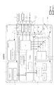
図1は、本実施形態を示す画像形成装置の構成を説明するブロック図である。本例は、画像形成装置1を、スキャナ装置2とプリンタ装置4を備えるMFP(Multi Function Printer)で構成した例である。本実施形態では、複数の処理手段として、スキャナ装置2とプリンタ装置4、およびコントローラ3,画像処理ユニット5等を備え、電源装置6から対応する電源が給電されることで、対応する処理を実行する。また、本ン実施形態では、後述する外部記憶装置33には、データとして、種々のデータが記憶されている実施形態を説明する。ここで、種々のデータとは、印刷データ、電源指示データ、制御テキストデータ(詳細は後述するPower.txt)
FIG. 1 is a block diagram illustrating the configuration of the image forming apparatus according to the present exemplary embodiment. In this example, the
図1において、2は原稿読取りを行うスキャナ装置で、CISセンサ等を備え、原稿から光学的に画像を読み取りデジタル画像に変換する。4はプリンタ装置で、感光体に現像されたトナー像をシートに転写した後、熱定着ユニットを用いて現像剤をシート上に定着させる。
8は操作部で、液晶タッチパネルのような設定状態表示およびユーザ操作可能な操作表示画面と、テンキーのような操作ボタンから構成される。
In FIG. 1,
An operation unit 8 includes a setting state display such as a liquid crystal touch panel and an operation display screen that can be operated by a user, and operation buttons such as a numeric keypad.
14はハードディスク装置(HDD)で、デジタル画像や制御プログラム等を記憶する。7はFAX装置で、電話回線等に接続してデジタル画像データを送信したり受信したりする。33はUSBストレージやSDカード等で構成される外部記憶装置で、外部記憶装置I/F32を介してCPU13の内部バスに接続され、CPU13によりデータの読み出しやデータの書き込みが実行される。3はコントローラ(制御装置)で、CPU13を備え、各モジュールに指示を出す事により画像形成装置上でジョブを実行する。
画像形成装置1は、LAN9経由でコンピュータ10からデジタル画像の入出力、ジョブの発行や機器の指示等も行なうことが可能である。
A hard disk device (HDD) 14 stores a digital image, a control program, and the like. A
The
スキャナ装置2は、自動的に原稿束を逐次入れ替えることが可能な原稿給紙ユニット11、原稿を光学スキャンしデジタル画像に変換する事が可能なスキャナユニット12から成り、変換された画像データはコントローラ3に送信される。
The
プリンタ装置4は、紙束から一枚ずつ逐次給紙可能な給紙ユニット18、給紙したシートに画像データを印刷するためのマーキングユニット16、印刷後のシートを排紙するための排紙ユニット17から成る。コントローラ3はCPU13を有し、スキャナ装置2及びプリンタ装置4と画像データの送受信及び保存を行う。すなわち、コントローラ3ではスキャナ装置2から受信した画像データを、メモリ15に一時保存する。
The printer device 4 includes a
その後、ハードディスク装置14へと画像データを格納する事で画像のスキャンと保存が完了する。コントローラ3は、ハードディスク装置14から画像データをメモリ15に一時保存し、メモリ15からプリンタ装置4に画像データを送信することによりプリント出力を行うことができる。
Thereafter, the image data is stored in the hard disk device 14 to complete scanning and saving of the image. The
また、汎用画像処理部19を有し、メモリ15に保存した画像データを汎用画像処理部19で、例えば縮小等の処理を行ったものを再度メモリ15に保存することが可能な画像処理ユニット5を持っている。この汎用画像処理部19は必要に応じて様々な場面で使用する。6は電源装置で、画像形成装置1における電源を供給する。なお、画像形成装置がOFF時、AC電源29はスイッチ30により絶縁されている。そして、スイッチ30をONにすることでAC−DCコンバータ20にAC電源が供給され、DC電源が作られる。本実施形態に示す画像形成装置はCPU13の指示により装置全体を4つの独立した電源制御が可能である。
Further, the
すなわち、CPU13からのスイッチ手段21により、コントローラ部電力25の電源をOFF/ON制御可能である。同様に、スイッチ手段22はプリンタ部電力28、スイッチ手段23はスキャナ部電力26、スイッチ手段24は汎用画像処理部電力27の電源をOFF/ON制御可能である。CPU13はこれらのスイッチ手段21から24を用いることで、適切に画像形成装置1の必要な場所に電力を供給する。
In other words, the power of the controller unit power 25 can be turned off / on by the switch means 21 from the CPU 13. Similarly, the switch unit 22 can control the power of the printer unit power 28, the
本実施形態に示す画像形成装置1は、コントローラ3が制御する操作部8を有し、オペレータ操作もしくは、LAN9からの指示をCPU13が解釈し、多彩なジョブを実行可能である。以下、実行可能な機能処理例を説明する。
〔複写機能〕
スキャナ装置2から読み込んだ画像をハードディスク装置14に保存し、同時にプリンタ装置4を使用して印刷を行なう。
〔画像送信機能〕
スキャナ装置2から読み込んだ画像をハードディスク装置14に保存し、LAN9を経由してコンピュータ10に送信する。
〔画像保存機能〕
スキャナ装置2から読み込んだ画像をハードディスク装置14に保存し、必要に応じて画像送信や画像印刷を行なう。
〔画像印刷機能〕
コンピュータ10から送信された例えばページ記述言語を解析し、プリンタ装置4で印刷する。
〔FAX受信プリント〕
FAX装置7から受信したFAX画像をハードディスク装置14に保存し、同時にプリンタ装置4を使用して印刷を行う。
The
[Copy function]
The image read from the
(Image transmission function)
The image read from the
(Image saving function)
The image read from the
(Image printing function)
For example, the page description language transmitted from the
[FAX reception print]
The FAX image received from the
〔FAX転送処理〕
FAX装置7から受信したFAX画像をハードディスク装置14に保存し、同時にLAN9を経由してコンピュータ10等に転送する。
〔FAXメモリ受信処理〕
FAX装置7から受信したFAX画像をハードディスク装置14に保存し、オペレータからの参照を待つ。
〔FAX送信処理〕
スキャナ装置2から読み込んだ画像をハードディスク装置14に保存し、同時にFAX装置7から公衆回線に送信する。
〔外部記憶装置ダイレクトプリント〕
USBストレージやSDカード等の外部記憶装置33に格納されている画像を外部記憶装置I/F32を介してハードディスク装置14に保存し、必要に応じて画像印刷を行なう。
〔外部記憶装置ダイレクト保存機能〕
スキャナ装置2から読み込んだ画像をハードディスク装置14に保存し、必要に応じて外部記憶装置I/F32を介してUSBストレージやSDカード等の外部記憶装置33に格納する。
[FAX transfer processing]
The FAX image received from the
[FAX memory reception processing]
The FAX image received from the
[FAX transmission processing]
The image read from the
[External storage device direct print]
An image stored in the external storage device 33 such as a USB storage or an SD card is stored in the hard disk device 14 via the external storage device I /
[External storage device direct save function]
An image read from the
〔外部記憶装置保存機能〕
ハードディスク装置14に保存してあるデータを、外部記憶装置I/F32を介して外部記憶装置33に格納する。なお、多くのケースでハードディスク装置14を介在するのは、ジョブに失敗した場合や、電源断等の異常状態からリカバリするためである。
以下に画像形成装置が遷移可能な電力状態について説明する。
〔スリープ状態〕
このモードは画像形成装置1自体の電力を可能な限り落した状態である。
[External storage device saving function]
Data stored in the hard disk device 14 is stored in the external storage device 33 via the external storage device I /
The power state in which the image forming apparatus can transition will be described below.
[Sleep state]
In this mode, the power of the
具体的には、CPU13の周辺デバイスは一般的なサスペンド状態(ACPI−S3等)とし、ジョブを検出可能な部分(スリープ時電力31)のみの通電を行い、装置全体の電力を非常に少ない電力状態にすることができる。 Specifically, the peripheral device of the CPU 13 is in a general suspend state (ACPI-S3 or the like), and only the portion where the job can be detected (sleep power 31) is energized, so that the power of the entire apparatus is very low. Can be in a state.
具体的には、CPU13は装置の状態をメモリ15に保存し、スイッチ手段21により自分自身を含むコントローラ部電力25の電源を落とす。この時、CPU13自身が動作しなくなるが、スリープ時電力31がハードウエア的にONされ、ジョブが来たことだけが分かる状態となる。
Specifically, the CPU 13 stores the state of the apparatus in the memory 15 and turns off the power of the controller unit power 25 including itself by the switch means 21. At this time, the CPU 13 itself does not operate, but the sleep-
そして、例えば、LAN9からのネットワーク受信、FAX装置7からのFAXコール、操作部8の操作(スリープ復帰ボタン押下等)がなされた時に、ハードウエア的にコントローラ部電力25がONとなる。
CPU13はメモリ15に保存された装置の状態をメモリ15から読みだして、再設定を行い、コントローラ部電力25の電源がOFFされる直前の状態に復帰し、スタンバイ状態へと移行する。
スリープ状態はハードウエアの多くが動作できない状態であるため、スタンバイ状態に遷移するだけの機能しかない。ジョブはスタンバイ状態に移行してから受け付ける。
For example, when a network reception from the LAN 9, a FAX call from the
The CPU 13 reads the state of the device stored in the memory 15 from the memory 15, performs resetting, returns to the state immediately before the power of the controller unit power 25 is turned off, and shifts to the standby state.
Since the sleep state is a state in which most of the hardware cannot operate, it has only a function for making a transition to the standby state. The job is accepted after shifting to the standby state.
〔スタンバイ状態〕
コントローラ部電力25が通電されている状態である。
具体的には、操作部8からのオペレータによる操作、LAN9からのネットワーク経由のジョブ等を受け付ける。
ことのとき、操作部8の操作表示画面の液晶バックライトは消灯されており、オペレータ操作時(スリープ復帰ボタン押下等)で液晶バックライトが点灯し、操作表示画面が起動される。
[Standby]
This is a state where the controller power 25 is energized.
Specifically, an operation by an operator from the operation unit 8, a job via a network from the LAN 9, and the like are received.
At this time, the liquid crystal backlight of the operation display screen of the operation unit 8 is turned off, and the liquid crystal backlight is turned on when the operator operates (such as pressing the sleep return button), and the operation display screen is activated.
プリンタ部電力28、スキャナ部電力26、汎用画像処理部電力27はOFFとなっているため、CPU13はスイッチ手段22から24の使用するデバイスの電源を通電させた後に、所定のジョブを実行する。
例えば以下のようにジョブ種に応じて各デバイスの電源をONにする。
〔複写機能〕
スキャナ部電力26とプリンタ部電力28をONにし、先に述べたように複写機能を実現する。
〔画像送信機能〕
スキャナ部電力26のみをONにし、読みとった画像データを送信する。
〔画像保存機能〕
スキャナ部電力26のみをONにし、読みとった画像データを保存する。
〔画像印刷機能〕
プリンタ部電力28のみをONにし、様々な画像データを印刷する。
Since the printer unit power 28, the scanner unit power 26, and the general-purpose image
For example, the power of each device is turned on according to the job type as follows.
[Copy function]
The scanner unit power 26 and the printer unit power 28 are turned on to realize the copying function as described above.
(Image transmission function)
Only the scanner power 26 is turned on and the read image data is transmitted.
(Image saving function)
Only the scanner power 26 is turned on and the read image data is stored.
(Image printing function)
Only the printer unit power 28 is turned on to print various image data.
〔FAX受信プリント〕
プリンタ部電力28と汎用画像処理部電力27をONにし、受信したFAX画像に汎用画像処理を施したのちに印刷する。
〔FAX転送処理〕
汎用画像処理部電力27のみをONにし、FAX受信したデータを汎用画像処理したのちに転送する。
〔FAXメモリ受信処理〕
汎用画像処理部電力27のみをONにし、FAX受信したデータを汎用画像処理した後、ハードディスク装置14に保存する。
〔FAX送信処理〕
スキャナ部電力26と汎用画像処理部電力27をONにし、読み込んだFAX画像データを公衆回線に送信する。
〔外部記憶装置ダイレクトプリント〕
USBストレージやSDカード等の外部記憶装置33が接続されている時、プリンタ部電力28をONにし、様々な画像データを印刷する。
〔外部記憶装置ダイレクト保存機能〕
[FAX reception print]
The printer unit power 28 and the general-purpose image
[FAX transfer processing]
Only the general-purpose image
[FAX memory reception processing]
Only the general-purpose image
[FAX transmission processing]
The scanner unit power 26 and the general-purpose image
[External storage device direct print]
When an external storage device 33 such as a USB storage or an SD card is connected, the printer unit power 28 is turned on to print various image data.
[External storage device direct save function]
USBストレージやSDカード等の外部記憶装置33が接続されている時、スキャナ部電力26をONにし、読みとった画像データを外部記憶装置I/F32を介してUSBストレージやSDカード等の外部記憶装置33に格納する。
〔外部記憶装置保存機能〕
When an external storage device 33 such as a USB storage or an SD card is connected, the scanner unit power 26 is turned on, and the read image data is transferred to the external storage device such as a USB storage or an SD card via the external storage device I /
[External storage device saving function]
USBストレージやSDカード等の外部記憶装置33が接続されている時、ハードディスク装置14に保存してあるデータを外部記憶装置I/F32を介してUSBストレージやSDカード等の外部記憶装置33に格納する。なお、いずれのジョブ種の場合であっても、汎用画像処理部電力27をONにしても構わない。
ジョブが完了したらデバイスの電源を落とすことで、使用する時だけ必要なデバイスのみを通電させることが可能となり、スタンバイ時の待機電力を削減することが可能となる。
When an external storage device 33 such as a USB storage or SD card is connected, data stored in the hard disk device 14 is stored in the external storage device 33 such as a USB storage or SD card via the external storage device I /
When the job is completed, by turning off the power of the device, only the necessary device can be energized only when it is used, and the standby power during standby can be reduced.
図2A〜図2Fは、図1に示した画像形成装置1のハードウエアに対する通電状態を示す図である。
図2Aは通常状態に対応し、コントローラ部電力25、スキャナ部電力26、汎用画像処理部電力27、プリンタ部電力28が通電されている状態である。
例えば、複写機能使用時の電力状態である。
図2Bはスリープ状態に対応し、前述のとおり、画像形成装置1自体の電力を可能な限り落した状態である。この際、各部電力25〜28は通電されていない。また、このとき、コントローラ3および外部記憶装置I/F32は通電されていないため、外部記憶装置33が接続されてもCPU13は外部記憶装置33を認識できない。
2A to 2F are diagrams showing energized states of the hardware of the
FIG. 2A corresponds to the normal state, in which the controller unit power 25, the scanner unit power 26, the general-purpose image
For example, the power state when the copy function is used.
FIG. 2B corresponds to the sleep state, and as described above, the power of the
図2Cはスタンバイ状態で、前述のとおり、コントローラ部電力25が通電されている状態である。この際、スキャナ部電力26、汎用画像処理部電力27、プリンタ部電力28は通電されていない。また、このとき、コントローラ3および外部記憶装置I/F32は通電されているため、外部記憶装置33が接続されてもCPU13は外部記憶装置33を認識できる。
図2Dは第1の省電力状態に対応し、コントローラ部電力25、スキャナ部電力26、汎用画像処理部電力27が通電されている状態である。この際、プリンタ部電力28は通電されていない。また、第1の省電力状態とは、画像送信機能/画像保存機能/FAX送信処理/外部記憶装置ダイレクト保存機能使用時の電力状態に対応する。
図2Eは第2の省電力状態に対応し、コントローラ部電力25、汎用画像処理部電力27、プリンタ部電力28が通電されている状態である。この際、スキャナ部電力26は通電されていない。また、第2の省電力状態とは、画像印刷機能/FAX受信プリント/外部記憶装置ダイレクトプリント使用時の電力状態に対応する。
FIG. 2C shows a standby state in which the controller unit power 25 is energized as described above. At this time, the scanner unit power 26, the general-purpose image
FIG. 2D corresponds to the first power saving state, in which the controller unit power 25, the scanner unit power 26, and the general-purpose image
FIG. 2E corresponds to the second power saving state, in which the controller unit power 25, the general-purpose image
図2Fは第3の省電力状態に対応し、コントローラ部電力25、汎用画像処理部電力27が通電されている状態である。この際、プリンタ部電力28、スキャナ部電力26は通電されていない。また、第3の省電力状態とは、FAX転送処理/FAXメモリ受信処理/外部記憶装置保存機能使用時の電力状態に対応する。ただし、上記各電力状態において、各装置・ユニットに電力を供給するAC−DCコンバータ20はAC電源29より電力が供給されている。
また、画像形成装置1が図2Cに示すスタンバイ状態のとき、操作部8は通電されているが、電力低減のため操作表示画面は消灯・停止している。図2Cに示すスタンバイ状態から図2Aに示す通常状態、図2dに示す第1の省電力状態、図2Eに示す第2の省電力状態に遷移した時、操作部8の操作表示画面が起動・操作できる状態となる。
FIG. 2F corresponds to the third power saving state, in which the controller unit power 25 and the general-purpose image
When the
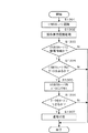
図3は、本実施形態を示す画像形成装置の制御方法を説明するフローチャートである。本例は、図1に示した外部記憶装置I/F32に外部記憶装置33が接続されたことを認識して実行される電力制御例である。なお、各ステップは、CPU13がHDD14等に記憶された制御プログラムを実行することで実現される。
以下、説明では、外部記憶装置33の一例として、USBストレージが接続された場合を想定し、前述のとおり、図2Bに示したスリープ状態ではUSBストレージを認識できないため、フローチャートの開始における画像形成装置1の電力状態は、図2Cに示したスタンバイ状態として記述する。
FIG. 3 is a flowchart illustrating a method for controlling the image forming apparatus according to the present exemplary embodiment. This example is a power control example that is executed by recognizing that the external storage device 33 is connected to the external storage device I /
Hereinafter, in the description, it is assumed that a USB storage is connected as an example of the external storage device 33. As described above, the USB storage cannot be recognized in the sleep state illustrated in FIG. The power state of 1 is described as the standby state shown in FIG. 2C.
画像形成装置1の電力状態が図2Cに示すスタンバイ状態にあるとき、S301で、CPU13が外部記憶装置I/F32を介してUSBストレージが接続されていると認識し、S302に移行する。S302で、ユーザが画像形成装置1を操作できるようCPU13は操作部8の操作表示画面を起動し、S303に移行する。
S303で、CPU13は接続されているUSBストレージが、画像形成装置1が図2Cに示したスタンバイ状態中に新規に接続されたかを判断する。ここで、USBストレージが新規に接続されたとCPU13が判断した場合は、CPU13に対してconnect信号が入力される。
When the power state of the
In S303, the CPU 13 determines whether the connected USB storage is newly connected while the
このため、connect信号がCPU13に対して入力されている場合、USBストレージが新規接続であり、connect信号が入力されていない場合は。既にUSBストレージが接続された状態のままで接続状態に変化がなかった場合(つまり、新規接続ではない)と判断できる。
このとき、USBストレージが新規接続であるとCPU13が判断した場合は、S304に移行し、新規接続でないとCPU13が判断した場合は、CPU13は通電等の処理を行わない。
For this reason, when the connect signal is input to the CPU 13, the USB storage is newly connected and the connect signal is not input. It can be determined that the USB storage is already connected and the connection state has not changed (that is, it is not a new connection).
At this time, if the CPU 13 determines that the USB storage is a new connection, the process proceeds to S304. If the CPU 13 determines that the USB storage is not a new connection, the CPU 13 does not perform processing such as energization.
S304で、CPU13は外部記憶装置I/F32を介して、USBストレージに対してデータ検出処理をする。ここで、CPU13がUSBストレージ内のデータを検出した場合、S305に移行し、データを検出できなかったとCPU13が判断した場合、CPU13は通電等の処理を行わない。
S305で、CPU13は、スキャナ部電力26、汎用画像処理部電力27、プリンタ部電力28を通電し、画像形成装置1の電力状態を図2Aの通常状態に遷移させる。
なお、S304で、CPU13がUSBストレージ内のデータを検出できないとCPU13が判断した場合、ユーザはスキャンしたデータをUSBストレージ内に格納することが考えられる。このとき、S305で、CPU13が特定されるスキャナ部電力26、汎用画像処理部電力27を通電し、画像形成装置1の電力状態を図2Dに示す第1の省電力状態に遷移させるように制御しても構わない。
In S304, the CPU 13 performs data detection processing on the USB storage via the external storage device I /
In S305, the CPU 13 energizes the scanner unit power 26, the general-purpose image
In S304, if the CPU 13 determines that the CPU 13 cannot detect the data in the USB storage, the user may store the scanned data in the USB storage. At this time, in step S305, the CPU 13 controls the power of the scanner unit 26 and the general-purpose
例えば、ユーザがUSBストレージを画像形成装置1の外部記憶装置I/F32に接続する場合、USBストレージ内にデータがないとき、USBストレージからのプリントは実行できない。このため、本実施形態では、プリンタ装置4へ通電しないため、消費電力を抑えることが可能となる。
また、USBストレージ内にデータがある場合、ユーザはUSBストレージからのプリントを行う可能性がある。このため、データがある場合にはプリンタ装置4へ通電するため、予めプリンタ装置4内の定着ユニットを昇温することが可能となり、効率的にプリントジョブを実行できる。
For example, when the user connects the USB storage to the external storage device I /
If there is data in the USB storage, the user may print from the USB storage. For this reason, when there is data, the printer device 4 is energized, so the temperature of the fixing unit in the printer device 4 can be raised in advance, and a print job can be executed efficiently.
〔第2実施形態〕
図4は、本実施形態を示す画像形成装置の制御方法を説明するフローチャートである。本例は、図1に示した外部記憶装置I/F32に外部記憶装置33が接続されたことを認識して実行される電力制御例である。なお、各ステップは、CPU13がHDD14等に記憶された制御プログラムを実行することで実現される。
[Second Embodiment]
FIG. 4 is a flowchart illustrating a method for controlling the image forming apparatus according to the present exemplary embodiment. This example is a power control example that is executed by recognizing that the external storage device 33 is connected to the external storage device I /
なお、本実施形態では、第1実施形態と同様、外部記憶装置33はUSBストレージとし、前述のとおり、図2Bに示すスリープ状態ではUSBストレージを認識できないため、フローチャートの開始における画像形成装置1の電力状態は、図2Cに示すスタンバイ状態として記述する。 In the present embodiment, as in the first embodiment, the external storage device 33 is a USB storage, and as described above, the USB storage cannot be recognized in the sleep state shown in FIG. 2B. The power state is described as the standby state shown in FIG. 2C.
画像形成装置1の電力状態が図2Cに示すスタンバイ状態にあるとき、S401で、CPU13が外部記憶装置I/F32を介してUSBストレージが接続されていると認識し、S402に移行する。
S402で、ユーザが画像形成装置1を操作できるようCPU13は操作部8の操作表示画面を起動し、S403に移行する。S403で、CPU13は接続されているUSBストレージが、画像形成装置1が図2Cに示すスタンバイ状態中に新規に接続されたかを判断する。ここで、USBストレージが新規に接続されたとCPU13が判断した場合は、CPU13に対してconnect信号が入力される。
When the power state of the
In S402, the CPU 13 activates the operation display screen of the operation unit 8 so that the user can operate the
このため、connect信号が入力されていると判断された場合は、USBストレージが新規接続状態であり、connect信号が発行されていないと判断した場合は接続された状態のままであった(つまり、新規接続ではない)と判断できる。
このとき、USBストレージが新規接続であると判断した場合は、S404に移行し、新規接続でないと判断した場合は、CPU13は通電等の処理を行わず、本処理を終了する。
S404で、CPU13は外部記憶装置I/Fを介して、USBストレージに対してデータ検出処理をする。ここで、CPU13がUSBストレージ内のデータを検出したと判断した場合、S405に移行し、データを検出できないと判断した場合、CPU13は通電等の処理を行わず、本処理を終了する。
S405で、CPU13は外部記憶装置I/Fを介して、USBストレージ内のデータ種別を検出する。
For this reason, when it is determined that the connect signal is input, the USB storage is in a newly connected state, and when it is determined that the connect signal has not been issued, the USB storage device remains connected (that is, This is not a new connection.
At this time, if it is determined that the USB storage is a new connection, the process proceeds to S404. If it is determined that the USB storage is not a new connection, the CPU 13 ends the process without performing a process such as energization.
In S404, the CPU 13 performs data detection processing on the USB storage via the external storage device I / F. If the CPU 13 determines that the data in the USB storage has been detected, the process proceeds to S405. If the CPU 13 determines that the data cannot be detected, the CPU 13 terminates the process without performing a process such as energization.
In S405, the CPU 13 detects the data type in the USB storage via the external storage device I / F.
ここで、CPU13がUSBストレージ内に画像形成装置1が印刷可能なデータを検出しているかどうかを判断する。ここで、画像形成装置1が印刷可能なデータを検出しているとCPU13が判断した場合、S406に移行し、印刷可能なデータを検出できていないとCPU13が判断した場合、CPU13は通電等の処理を行わず、本処理を終了する。
S406で、CPU13はスキャナ部電力26、汎用画像処理部電力27、プリンタ部電力28を通電し、画像形成装置1の電力状態を図2Aの通常状態に遷移させるように制御する。
Here, the CPU 13 determines whether or not the
In S <b> 406, the CPU 13 supplies power to the scanner unit power 26, the general-purpose image
なお、S404およびs405で、CPU13がUSBストレージ内のデータを検出できないと判断した場合および印刷可能なデータを検出できないと判断した場合、ユーザはスキャンしたデータをUSBストレージ内に格納することが考えられる。このとき、s406で、CPU13が特定されるスキャナ部電力26、汎用画像処理部電力27を通電し、画像形成装置1の電力状態を図2Dの第1の省電力状態に遷移させるように制御しても構わない。
In S404 and s405, if the CPU 13 determines that data in the USB storage cannot be detected or determines that printable data cannot be detected, the user may store the scanned data in the USB storage. . At this time, in
例えば、ユーザがUSBストレージを画像形成装置1の外部記憶装置I/F32に接続する場合、USBストレージ内に画像形成装置1が印刷可能なデータでないとき、USBストレージからのプリントは実行できない。このため、第2実施形態ではプリンタ装置4へ通電しないため、消費電力を抑えることが可能となる。
また、USBストレージ内に印刷可能なデータがある場合、ユーザはUSBストレージからのプリントを実行できる。このため、印刷可能なデータがある場合にはプリンタ装置4へ通電するため、予めプリンタ装置4内の定着ユニットを昇温することが可能となり、効率的にプリントジョブを実行できる。また、USBストレージ内データが印刷可能か否かの判定は、画像形成装置1がデータの拡張子やマジックナンバー等を参照することで実現可能である。
For example, when a user connects a USB storage to the external storage device I /
If there is printable data in the USB storage, the user can execute printing from the USB storage. Therefore, when there is printable data, the printer device 4 is energized, so that the temperature of the fixing unit in the printer device 4 can be raised in advance, and a print job can be executed efficiently. Whether the data in the USB storage can be printed can be determined by the
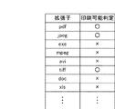
図5は、本実施形態を示す画像形成装置による印刷可能性の判断情報を示す図である。本例は、USBストレージ内データが印刷可能か否かの判断を、データの拡張子で判断する例である。
図5において、例えば、pdf/jpeg/tiffは画像データであり、画像形成装置1にデータを解析する手段があるため、印刷可能と判定される。
doc(Word)/xlS(Excel)は、画像形成装置1内にデータを解析する手段がないため、印刷不可能と判定される。なお、exe(実行ファイル)は画像データではなく、mpegやaviは動画データであるため、印刷対象外となり印刷不可能と判定される。
FIG. 5 is a diagram illustrating printability determination information by the image forming apparatus according to the present exemplary embodiment. This example is an example of determining whether the data in the USB storage can be printed based on the data extension.
In FIG. 5, for example, pdf / jpeg / tiff is image data, and it is determined that printing is possible because the
doc (Word) / xlS (Excel) is determined to be unprintable because there is no means for analyzing data in the
〔第3実施形態〕
図6は、本実施形態を示す画像形成装置の制御方法を説明するフローチャートである。本例は、図1に示した外部記憶装置I/F32に外部記憶装置33が接続されたことを認識して実行される電力制御例である。なお、各ステップは、CPU13がHDD14等に記憶された制御プログラムを実行することで実現される。
[Third Embodiment]
FIG. 6 is a flowchart illustrating a method for controlling the image forming apparatus according to the present exemplary embodiment. This example is a power control example that is executed by recognizing that the external storage device 33 is connected to the external storage device I /
なお、本実施形態では、第1実施形態と同様、外部記憶装置33はUSBストレージとし、前述のとおり、図2Bに示すスリープ状態ではUSBストレージを認識できない。このため、フローチャートの開始における画像形成装置1の電力状態は、図2Cに示すスタンバイ状態として記述する。
In the present embodiment, as in the first embodiment, the external storage device 33 is a USB storage, and as described above, the USB storage cannot be recognized in the sleep state shown in FIG. 2B. For this reason, the power state of the
画像形成装置1の電力状態が図2Cに示すスタンバイ状態にあるとき、S601で、CPU13が外部記憶装置I/F32を介してUSBストレージが接続されていると認識し、S602に移行する。S602で、ユーザが画像形成装置1を操作できるようCPU13は操作部8の操作表示画面を起動し、S603に移行する。
S603で、画像形成装置1はスリープ状態から復帰するための内部処理を実行し、S604に移行する。
S604で、CPU13は接続されているUSBストレージが、画像形成装置1が図2Cに示すスタンバイ状態中に新規に接続されたかを判断する。ここで、USBストレージが新規に接続されたとCPUが判断した場合は、外部記憶装置I/F32からCPU13に対してconnect信号が入力される。
When the power state of the
In step S603, the
In step S604, the CPU 13 determines whether the connected USB storage is newly connected while the
このため、外部記憶装置I/F32からconnect信号が発行されている場合はUSBストレージが新規接続であり、外部記憶装置I/F32からconnect信号が発行されていない場合は接続された状態のままであったと判定できる。つまり、新規接続ではないと判定される。
このとき、USBストレージが新規接続であるとCPU13が判断した場合は、S605に移行し、新規接続でないとCPU13が判断した場合は、CPU13は通電等の処理を行わず、本処理を終了する。
S605で、CPU13は外部記憶装置I/Fを介して、USBストレージに対して制御用テキストデータを検出しているかどうかを判断する。
For this reason, when a connect signal is issued from the external storage device I /
At this time, if the CPU 13 determines that the USB storage is a new connection, the process proceeds to S605. If the CPU 13 determines that the USB storage is not a new connection, the CPU 13 terminates the process without performing a process such as energization.
In step S605, the CPU 13 determines whether control text data is detected for the USB storage via the external storage device I / F.
ここで、CPU13がUSBストレージ内の制御用テキストデータ(Power.txt)を検出したと判断した場合、S606に移行し、データを検出できないとCPU13が判断した場合、S607に移行する。画像形成装置は全箇所を通電させるため、図2Cに示す通常状態に入る。 If the CPU 13 determines that control text data (Power.txt) in the USB storage has been detected, the process proceeds to S606. If the CPU 13 determines that data cannot be detected, the process proceeds to S607. The image forming apparatus enters a normal state shown in FIG.
S606で、CPU13は、Power.txtの記載内容を解析して、通電箇所を決める。本実施形態で通電可能な箇所はスキャナ部電力26、汎用画像処理部電力27、プリンタ部電力28である。その後、S608に移行する。
In step S606, the CPU 13 determines whether the Power. Analyzing the description of txt, determine the energization location. In the present embodiment, the portions that can be energized are the scanner unit power 26, the general-purpose image
S608では、CPU13はS606で決められた通電箇所に対して通電するように図1に示したスイッチを制御する。前述通り制御用テキストデータ(Power.txt)は存在しないとCPU13が判断した場合、全ての機能(スキャナ部電力26、汎用画像処理部電力27、プリンタ部電力28である)に通電して、本処理を終了する。なお、S607では、画像形成装置は全箇所を通電させるため、電力状態は、図2Aの通常状態に入る。
In S608, the CPU 13 controls the switch shown in FIG. 1 to energize the energized location determined in S606. As described above, when the CPU 13 determines that the control text data (Power.txt) does not exist, all the functions (the scanner unit power 26, the general-purpose image
例えば、ユーザがプリント専用のUSBストレージにPower.txt(プリンタはON、他機能全てOFF)を格納して、画像形成装置1の外部記憶装置I/F32に接続する場合、制御用テキストデータを解析した結果、プリンタ装置4にしか通電しないため、消費電力を抑えることが可能となる。このため、データがある場合にはプリンタ装置4へ通電し、予めプリンタ装置4内の定着ユニットを昇温することが可能となり、効率的にプリントジョブを実行できる。
For example, when a user uses Power. When storing txt (printer is ON, all other functions are OFF) and connecting to the external storage device I /
図7は、図1に示した外部記憶装置33に記憶される制御用テキストデータの一例を示す図である。本例は、制御用テキストデータにプリンタ、スキャン、FAX送信処理という機能とその通電状態が記載されている。
画像形成装置1はこの制御用テキストデータを参照してCPU13は、、汎用画像処理部27、プリンタ部電力28を通電し、スキャナ部電力26には通電せず、画像形成装置1の電力状態を図2Eに示す第2の省電力状態へ遷移させる制御を実行する。
〔第4実施形態〕
図8は、本実施形態を示す画像形成装置の制御方法を説明するフローチャートである。本例は、図1に示した外部記憶装置I/F32に外部記憶装置33が接続されたことを認識して実行される電力制御例である。なお、各ステップは、CPU13がHDD14等に記憶された制御プログラムを実行することで実現される。
FIG. 7 is a diagram showing an example of control text data stored in the external storage device 33 shown in FIG. In this example, functions such as a printer, scan, and FAX transmission processing and their energization states are described in the control text data.
The
[Fourth Embodiment]
FIG. 8 is a flowchart illustrating a method for controlling the image forming apparatus according to the present exemplary embodiment. This example is a power control example that is executed by recognizing that the external storage device 33 is connected to the external storage device I /
なお、本実施形態では、第1実施形態と同様、外部記憶装置33はUSBストレージとし、前述のとおり、図2Bに示すスリープ状態ではUSBストレージを認識できない。このため、フローチャートの開始における画像形成装置1の電力状態は、図2Cに示すスタンバイ状態として記述する。なお、S601〜S607に関しては、図6で説明済であるため、省略する。
S708で、CPU13は、usbストレージから読み出したPower.txtの中身を解析して、行われるジョブに応じた通電順番を図9に示す制御要テキストデータに基づいて決める。その後S709に移行する。
In the present embodiment, as in the first embodiment, the external storage device 33 is a USB storage, and as described above, the USB storage cannot be recognized in the sleep state shown in FIG. 2B. For this reason, the power state of the
In step S708, the CPU 13 reads the Power. The contents of txt are analyzed, and the energization order corresponding to the job to be performed is determined based on the control required text data shown in FIG. Thereafter, the process proceeds to S709.
S709では、CPU13がPower.txtで指定された通り通電する。一部自動的に行えるジョブ(たとえば文書・画像の印刷)は自動的に行う。それによってユーザの手間を省けることができる。また不要な箇所の電源を切り落とすことで消費電力を抑えることができる。 In S709, the CPU 13 determines that the Power. Energize as specified by txt. Some jobs that can be automatically performed (for example, printing of documents and images) are automatically performed. Thereby, it is possible to save the user's trouble. In addition, power consumption can be suppressed by cutting off the power at unnecessary portions.
なお、前述通り制御用テキストデータ(Power.txt)は存在しない場合全ての機能(スキャナ部電力26、汎用画像処理部電力27、プリンタ部電力28である)に通電する。これによってどんな状況でもユーザは画像形成装置を利用できるようになる。
Note that as described above, when there is no control text data (Power.txt), all the functions (the scanner unit power 26, the general-purpose image
図9は、図1に示した外部記憶装置33に記憶される制御用テキストデータの一例を示す図である。本例は、制御用テキストデータにプリンタ、スキャン、FAX送信処理という機能とその通電順番・実行ターゲットが記載されている。画像形成装置1はこのデータを参照して順次に機能に通電して、一部ジョブを自動的に実行することもある。
なお、図9に示す例では、以下の順番で電力制御が実行される。
制御用テキストデータによれば、プリント→コピー→スキャン→処理して発送と記憶されている。そこで、CPU13は、画像形成装置の電力状態を以下のように遷移させるように制御する。図2Eに示す第2の省電力状態→図2Aに示す通常状態→図2Dに示す第1の省電力状態→図2Fに示す第3の省電力状態。
これにより、図1に示したハードウエアのうち、通電する箇所は以下通り遷移する。
FIG. 9 is a diagram showing an example of control text data stored in the external storage device 33 shown in FIG. In this example, functions such as a printer, a scan, and a FAX transmission process and their energization order and execution target are described in the control text data. The
In the example illustrated in FIG. 9, power control is executed in the following order.
According to the control text data, print → copy → scan → process and send is stored. Therefore, the CPU 13 controls the power state of the image forming apparatus to transition as follows. The second power saving state shown in FIG. 2E → the normal state shown in FIG. 2A → the first power saving state shown in FIG. 2D → the third power saving state shown in FIG. 2F.
Thereby, in the hardware shown in FIG. 1, the energized portion changes as follows.
図2Eに示す第2の省電力状態では、汎用画像処理部27とプリンタ部電力28に通電ンする。そして、図2Aに示す通常状態では、汎用画像処理部27、プリンタ部電力28、スキャナ部電力26を通電する。そして、図2Dに示す第1の省電力状態では、汎用画像処理部27、スキャナ部電力26を通電し、図2Fに示す第3の省電力状態では、汎用画像処理部27を通電する。
In the second power saving state shown in FIG. 2E, the general-purpose
この中で、印刷と処理のターゲットは指定されているため、画像形成装置は自動的に印刷処理を実行して、外部記憶装置に記憶されたテキストデータで指定されたファイル(Print.jpg)を出力する。そして、第4番目の処理では、処理結果を指定されたメールアドレス(a@gmail.com)に自動的に送信することができる。しかし、第3番目のスキャンと第2の番目のコピーの場合には、画像形成装置に対してユーザが部数等を操作する必要があるため、自動実行することができない。 In this, since the target for printing and processing is specified, the image forming apparatus automatically executes the printing process, and the file (Print.jpg) specified by the text data stored in the external storage device is executed. Output. In the fourth process, the process result can be automatically transmitted to the designated e-mail address (a@gmail.com). However, in the case of the third scan and the second copy, the user needs to operate the number of copies and the like on the image forming apparatus, and therefore cannot be automatically executed.
このように、第3番目のスキャンと第2の番目のコピーの場合には、画像形成装置に対してユーザが部数等を操作する必要があるので、必要に応じて通電することで消費電力削減を実現できる。また、外部記憶装置に記憶されたジョブのうち、一部のジョブはユーザが手を加えずにできるため、迅速にジョブを仕上げることができる。これにより、通電時間の削減でさらに電力消費を削減できる。 As described above, in the case of the third scan and the second copy, the user needs to operate the number of copies or the like for the image forming apparatus. Can be realized. Further, among the jobs stored in the external storage device, some jobs can be done without the user's hands, so that the jobs can be completed quickly. Thereby, power consumption can be further reduced by reducing energization time.
〔第5実施形態〕
図10は、本実施形態を示す画像形成装置の制御方法を説明するフローチャートである。本例は、図1に示した外部記憶装置I/F32に外部記憶装置33が接続されたことを認識して実行される電力制御例である。なお、各ステップは、CPU13がHDD14等に記憶された制御プログラムを実行することで実現される。
[Fifth Embodiment]
FIG. 10 is a flowchart illustrating a method for controlling the image forming apparatus according to the present exemplary embodiment. This example is a power control example that is executed by recognizing that the external storage device 33 is connected to the external storage device I /
なお、本実施形態では、第1実施形態と同様、外部記憶装置33はUSBストレージとし、前述のとおり、図2Bに示すスリープ状態ではUSBストレージを認識できない。このため、フローチャートの開始における画像形成装置1の電力状態は、図2Cに示すスタンバイ状態として説明する。
In the present embodiment, as in the first embodiment, the external storage device 33 is a USB storage, and as described above, the USB storage cannot be recognized in the sleep state shown in FIG. 2B. Therefore, the power state of the
画像形成装置1の電力状態が図2Cに示すスタンバイ状態にあるとき、S1001で、CPU13が外部記憶装置I/F32を介してUSBストレージが接続されていると認識し、S1002に移行する。S1002で、ユーザが画像形成装置1を操作できるようCPU13は操作部8の操作表示画面を起動し、S1003に移行する。
S1003で、CPU13は接続されているUSBストレージが、画像形成装置1が図2Cに示すスタンバイ状態中に新規に接続されたかを判断する。ここで、USBストレージが新規に接続されたとCPU13が判断した場合は、外部記憶装置I/F32からCPU13に対してconnect信号が入力される。
When the power state of the
In step S1003, the CPU 13 determines whether the connected USB storage is newly connected while the
このため、connect信号がCPU13に入力されている場合は、USBストレージが新規接続であると判断でき、connect信号が入力されていない場合は、接続された状態のままであった(つまり、新規接続ではない)とCPU13は判断できる。
このとき、USBストレージが新規接続であるとCPU13が判断した場合は、S1004に移行し、新規接続でないとCPU13が判断した場合は、CPU13は通電等の処理を行わず、本処理を終了する。
S1004で、CPU13は、USBストレージが読み込み可能であるかを判定する。S1004の詳細については、図11の(A)にて説明する。
S1005で、CPU13は、USBストレージが書き込み可能であるかを判定する。S1005の詳細については、図11の(B)にて説明する。
S1006で、CPU13は、S1004、S1005での判定の結果に応じて、電力状態を以下のように遷移させる制御を実行する。
For this reason, when the connect signal is input to the CPU 13, it can be determined that the USB storage is newly connected, and when the connect signal is not input, the connected state remains (that is, the new connection). CPU13 can judge.
At this time, if the CPU 13 determines that the USB storage is a new connection, the process proceeds to S1004. If the CPU 13 determines that the USB storage is not a new connection, the CPU 13 ends the present process without performing a process such as energization.
In step S1004, the CPU 13 determines whether the USB storage can be read. Details of S1004 will be described with reference to FIG.
In step S1005, the CPU 13 determines whether the USB storage is writable. Details of S1005 will be described with reference to FIG.
In S1006, the CPU 13 executes control to change the power state as follows according to the determination results in S1004 and S1005.
すなわち、USBストレージが、読み込み可能で、かつ、書き込み可能であると判断できた場合、S1007へ進む。そして、CPU13は、スキャナ部電力26、汎用画像処理部電力27、プリンタ部電力28を通電し、画像形成装置1の電力状態を図2Aに示す通常状態に遷移させる制御を行い(S1007)、本処理を終了する。
That is, if it is determined that the USB storage is readable and writable, the process advances to step S1007. Then, the CPU 13 controls the power state of the
また、USBストレージが、読み込み不可で、かつ、書き込み可能であると判断できた場合、S1008へ進む。そして、CPU13は、特定された読み書き状態に基づいてスキャナ部電力26、汎用画像処理部電力27を通電し、画像形成装置1の電力状態を図2Dに示す第1の省電力状態に遷移させる制御を実行して(S1008)、本処理を終了する。これは、USBストレージが読み込み不可であり、USBストレージ内部のファイルを読み出しこれをプリントすることが出来ないため、プリント機能が使われる可能性が低いからである。
If it is determined that the USB storage is not readable and writable, the process advances to step S1008. Then, the CPU 13 energizes the scanner unit power 26 and the general-purpose image
また、USBストレージが、読み込み可能で、かつ、書き込み不可であると判断できた場合、S1009へ進む。そして、CPU13は、汎用画像処理部電力27、プリンタ部電力28を通電し、画像形成装置1の電力状態を図2Eに示した第2の省電力状態に遷移させる制御を実行して(S1009)、本処理を終了する。これは、USBストレージが書き込み不可であり、スキャン物を格納することができないため、スキャナ機能が使われる可能性が低いからである。
また、USBストレージが、読み込み不可で、かつ、書き込み不可であると判断できた場合、CPU13は通電の処理を行わず、本処理を終了する。
If it is determined that the USB storage is readable and not writable, the process advances to step S1009. Then, the CPU 13 energizes the general-purpose image
If it is determined that the USB storage cannot be read and cannot be written, the CPU 13 does not perform the energization process and ends this process.
図11は、本実施形態を示す画像形成装置の制御方法を説明するフローチャートである。本例は、図1に示した外部記憶装置I/F32に外部記憶装置33が接続されたことを認識して実行されるUSBストレージに対する判断処理例である。なお、各ステップは、CPU13がHDD14等に記憶された制御プログラムを実行することで実現される。また、図11の(A)はUSBストレージの読み込み可能判定処理例であり、図11の(B)はUSBストレージの書き込み可能判定処理例である。
まず、図11の(A)に示す読み込み可能判定処理を行う場合は、CPU13はUSBストレージがマウントされているかどうかを判断する。ここで、USBストレージがマウントされていないと判断した場合は、読み込み不可と判定して、本処理を終了する。
FIG. 11 is a flowchart illustrating a method for controlling the image forming apparatus according to the present exemplary embodiment. This example is a determination processing example for a USB storage executed by recognizing that the external storage device 33 is connected to the external storage device I /
First, when performing the readability determination process shown in FIG. 11A, the CPU 13 determines whether or not the USB storage is mounted. If it is determined that the USB storage is not mounted, it is determined that reading is not possible, and this process is terminated.
一方、S1101で、USBストレージがマウントされていると判断した場合、CPU13は、USBストレージに読み込み可能ファイルが存在するかどうかを判断する。ここで、読込可能なファイルが存在しないと判断した場合は、読み込み不可と判定して、本処理を終了する。
一方、S1102で、読込可能なファイルが存在すると判断した場合、読み込み可能と判定し(S1103)、本処理を終了する。
また、図11の(B)に示すUSBストレージの書き込み可能判定処理を行う場合は、CPU13はUSBストレージについてライトプロテクト(書き込みが禁止されている)されていないかを判断する(S1151)。ここで、USBストレージについてライトプロテクトされていると判断した場合、CPU13はUSBストレージの書き込み可能性は書き込み不可と判断して(S1156)、本処理を終了する。
一方、S1151で、CPU13は、USBストレージの書き込み可能であると判断した場合、USBストレージが書き込み可能でマウントされているかどうかを判断する(S1152)。ここで、USBストレージが書き込み可能でマウントされていないとCPU13が判断した場合、CPU13はUSBストレージの書き込み可能性は書き込み不可と判断して(S1156)、本処理を終了する。
一方、S1152で、USBストレージが書き込み可能でマウントされていると判断した場合、CPU13は、USBストレージにデータを書き込むための空き容量が存在するかどうかを判断する(S1153)。ここで、USBストレージにデータを書き込むための空き容量が存在しないと判断した場合、CPU13はUSBストレージの書き込み可能性は書き込み不可と判断して(S1156)、本処理を終了する。
On the other hand, if it is determined in S1101 that the USB storage is mounted, the CPU 13 determines whether a readable file exists in the USB storage. Here, when it is determined that there is no readable file, it is determined that reading is impossible, and this process is terminated.
On the other hand, if it is determined in S1102 that there is a readable file, it is determined that the file can be read (S1103), and the process ends.
When the USB storage writability determination process shown in FIG. 11B is performed, the CPU 13 determines whether or not the USB storage is write-protected (writing is prohibited) (S1151). If it is determined that the USB storage is write-protected, the CPU 13 determines that the writeability of the USB storage is not writable (S1156), and ends this process.
On the other hand, if it is determined in S1151 that the USB storage is writable, the CPU 13 determines whether the USB storage is writable and mounted (S1152). If the CPU 13 determines that the USB storage is writable and not mounted, the CPU 13 determines that the writeability of the USB storage is not writable (S1156), and ends this process.
On the other hand, if it is determined in S1152 that the USB storage is writable and mounted, the CPU 13 determines whether there is free space for writing data in the USB storage (S1153). If it is determined that there is no free space for writing data to the USB storage, the CPU 13 determines that the writeability of the USB storage is not writable (S1156), and ends this process.
一方、S1153で、USBストレージにデータを書き込むための空き容量が存在すると判断した場合、CPU13は、データの書き込みテストが成功したかどうかを判断する(S1154)。ここで、データの書き込みテストが成功しないとCPU13が判断した場合、CPU13はUSBストレージの書き込み可能性は書き込み不可と判断して(S1156)、本処理を終了する。
一方、S1154で、USBストレージにデータの書き込みテストが成功したと判断した場合、CPU13は、CPU13はUSBストレージの書き込み可能性は書き込み可能と判断して(S1155)、本処理を終了する。
On the other hand, if it is determined in S1153 that there is a free capacity for writing data to the USB storage, the CPU 13 determines whether the data write test is successful (S1154). If the CPU 13 determines that the data write test is not successful, the CPU 13 determines that the USB storage is not writable (S1156), and ends this process.
On the other hand, if it is determined in S1154 that the data write test has succeeded in the USB storage, the CPU 13 determines that the writeability of the USB storage is writable (S1155), and ends this process.
なお、S1151でのライトプロテクトとは、「誤消去防止スイッチ」などの名称で、USBストレージ本体の側面、もしくは、裏面についているスイッチが、有効になっている状態のことを示す。例えば、SDカードでは、カードの表面の左横部に誤消去防止スイッチが配置されており、メモリスティックでは、カードの裏面中央部に誤消去防止スイッチが配置されている。 Note that the write protection in S1151 is a name such as “erroneous erasure prevention switch” and indicates that the switch on the side surface or the back surface of the USB storage main body is enabled. For example, in an SD card, an erroneous erasure prevention switch is disposed on the left side of the front surface of the card, and in a memory stick, an erroneous erasure prevention switch is disposed in the center of the back surface of the card.
なお、第1〜第5実施形態では、図2Cに示すスタンバイ状態時にUSBストレージが新規に接続された場合について記載した。これに対して、図2Bに示すスリープ状態時でもハードウエア的にUSBストレージが新規に接続されたかを判定できれば、本実施形態を適用できる。
また、USBストレージが接続されたときの処理として、図2のいずれの電力状態へ移行するかをユーザが設定可能(例えば、操作部8で設定)であってもよい。
In the first to fifth embodiments, the case where the USB storage is newly connected in the standby state shown in FIG. 2C has been described. On the other hand, the present embodiment can be applied if it can be determined whether the USB storage is newly connected by hardware even in the sleep state shown in FIG. 2B.
Further, as a process when the USB storage is connected, the user may be able to set which power state in FIG. 2 is to be shifted to (for example, set by the operation unit 8).
〔第6実施形態〕
図12は、本実施形態を示す画像形成装置の制御方法を説明するフローチャートである。本例は、図1に示した外部記憶装置I/F32に外部記憶装置33が接続されたことを認識して実行される電力制御例である。なお、各ステップは、CPU13がHDD14等に記憶された制御プログラムを実行することで実現される。
[Sixth Embodiment]
FIG. 12 is a flowchart illustrating a method for controlling the image forming apparatus according to the present exemplary embodiment. This example is a power control example that is executed by recognizing that the external storage device 33 is connected to the external storage device I /
なお、本実施形態では、第1実施形態と同様、外部記憶装置33はUSBストレージとし、前述のとおり、図2Bに示すスリープ状態ではUSBストレージを認識できない。このため、フローチャートの開始における画像形成装置1の電力状態は、図2Cに示すスタンバイ状態として説明する。
画像形成装置1の電力状態が図2Cに示すスタンバイ状態にあるとき、S1201で、CPU13が外部記憶装置I/F32を介してUSBストレージが接続されていると認識し、S1202に移行する。S1202で、ユーザが画像形成装置1を操作できるようCPU13は操作部8の操作表示画面を起動し、S1203に移行する
In the present embodiment, as in the first embodiment, the external storage device 33 is a USB storage, and as described above, the USB storage cannot be recognized in the sleep state shown in FIG. 2B. Therefore, the power state of the
When the power state of the
S1203で、CPU13は接続されているUSBストレージが、画像形成装置1が図2Cに示すスタンバイ状態中に新規に接続されたかを判断する。ここで、USBストレージが新規に接続されたとCPU13が判断した場合は、外部記憶装置I/F32からCPU13に対してconnect信号が入力される。このため、connect信号がCPU13に入力されている場合はUSBストレージが新規接続であり、connect信号が入力されていない場合は接続された状態のままであった(つまり、新規接続ではない)とCPU13は判定できる。
このとき、USBストレージが新規接続であるとCPU13が判断した場合は、S1204に移行し、新規接続でないと判断した場合は、CPU13は通電等の処理を行わず、本処理を終了する。
In step S1203, the CPU 13 determines whether the connected USB storage is newly connected while the
At this time, if the CPU 13 determines that the USB storage is a new connection, the process proceeds to S1204. If it is determined that the USB storage is not a new connection, the CPU 13 ends the present process without performing a process such as energization.
そして、S1204では、CPU13は外部記憶装置I/Fを介して、USBストレージに対してデータ検出処理をする。具体的には、CPU13がUSBストレージ内のデータを検出しているかどうかを判断する。ここで、USBストレージ内のデータを検出しているとCPU13が判断した場合、S1205に移行し、データを検出できないとCPU13が判断した場合、CPU13は通電等の処理を行わず、本処理を終了する。
S1205で、USBストレージ内に画像形成装置1が印刷可能なデータを検出しているかどうかを判断する。ここで、CPU13が印刷可能なデータを検出していないと判断した場合は、CPU13は通電等の処理を行わず、本処理を終了する。
In step S1204, the CPU 13 performs data detection processing on the USB storage via the external storage device I / F. Specifically, it is determined whether the CPU 13 has detected data in the USB storage. If the CPU 13 determines that the data in the USB storage is detected, the process proceeds to S1205. If the CPU 13 determines that the data cannot be detected, the CPU 13 ends the process without performing the process such as energization. To do.
In step S1205, it is determined whether the
一方、S1205で、USBストレージ内に画像形成装置1が印刷可能なデータを検出しているとCPU13が判断した場合は、S1206へ進む。
S1206で、CPU13はUSBストレージ内に画像形成装置1が印刷可能なデータを識別処理するためにライセンス(権限)が必要であるか(権限状態)どうかを判断する。
これは、画像形成装置1において、一部制限された機能がある。そこで、一部制限された機能のライセンスを有効にすることによって、ユーザは当該機能を使用させることができる。そして、一部制限された機能のライセンスが画像形成装置1において有効であるとCPU13が判断した場合、例えばハードディスク装置14等の不揮発性記憶装置に当該機能のライセンスを有効にするライセンスフラグを立てる。そして、CPU13は、ハードディスク装置14にアクセスし、ライセンスフラグが立っていれば当該機能が使用可能であると判定して処理を進める。
On the other hand, if the CPU 13 determines in S1205 that the
In step S <b> 1206, the CPU 13 determines whether a license (authority) is necessary (authority state) to identify data that can be printed by the
This has a partially limited function in the
ここで、印刷可能データを処理するためにライセンスが必要であるとCPU13が判断した場合、S1207に移行し、ライセンスが必要でないと判断した場合、S1208に移行する。そして、CPU13は、ライセンスから特定される処理手段に対応するスキャナ部電力26、汎用画像処理部電力27、プリンタ部電力28を通電し、画像形成装置1の電力状態を図2(A)に示した通常状態にする。
S1207では、さらに、CPU13は画像形成装置1に印刷可能データを処理するためのライセンスが有効であるかどうかを判断する。ここで、印刷可能データを処理するためのライセンスが有効であるとCPU13が判断した場合、S1208に移行する。そして、CPU13はスキャナ部電力26、汎用画像処理部電力27、プリンタ部電力28を通電し、画像形成装置1の電力状態を図2(A)に示す通常状態にして、本処理を終了する。
If the CPU 13 determines that a license is required to process printable data, the process proceeds to S1207. If the CPU 13 determines that a license is not required, the process proceeds to S1208. Then, the CPU 13 energizes the scanner unit power 26, the general-purpose image
In step S1207, the CPU 13 further determines whether the license for processing printable data in the
一方、S1207で、ライセンスが有効でないとCPU13が判断した場合、CPU13は通電等の処理を行わず、本処理を終了する。
これにより、例えば、図5において、doc/xlsといったデータはライセンスを有効すると画像形成装置1で処理が可能とする。このような状態で、ユーザがUSBストレージを画像形成装置1の外部記憶装置I/F32に接続する場合、USBストレージ内にdoc/xlsといったデータしかない場合、画像形成装置1にdoc/xlsを処理するためのライセンスが有効でないと、USBストレージからのプリントは実行できない。
このため、本実施形態ではプリンタ装置4へ通電しないため、消費電力を抑えることが可能となる。また、画像形成装置1にdoc/xlsを処理するためのライセンスが有効であれば、ユーザはUSBストレージからのプリントを実行できる。
On the other hand, if the CPU 13 determines in S1207 that the license is not valid, the CPU 13 does not perform a process such as energization and ends this process.
Thus, for example, in FIG. 5, data such as doc / xls can be processed by the
For this reason, in this embodiment, since the printer apparatus 4 is not energized, power consumption can be suppressed. If the license for processing doc / xls is valid for the
このため、印刷可能なデータがある場合にはプリンタ装置4へ通電するため、予めプリンタ装置4内の定着ユニットを昇温することが可能となり、効率的にプリントジョブを実行できる。
なお、USBストレージ内の検出したデータにライセンスが必要なデータ、不要なデータが存在する場合、第1実施形態のように検出したデータが印刷可能であればプリンタ装置4へ通電してもよい。また、第6実施形態はUSBストレージ接続時だけでなく、コンピュータ10からLAN9を介して送られてきたデータであっても適用できる。
Therefore, when there is printable data, the printer device 4 is energized, so that the temperature of the fixing unit in the printer device 4 can be raised in advance, and a print job can be executed efficiently.
If the detected data in the USB storage includes data that requires a license or unnecessary data, the printer device 4 may be energized if the detected data can be printed as in the first embodiment. The sixth embodiment can be applied not only when the USB storage is connected, but also with data sent from the
〔第7実施形態〕
図13は、本実施形態を示す画像形成装置の制御方法を説明するフローチャートである。本例は、図1に示した外部記憶装置I/F32に外部記憶装置33が接続されたことを認識して実行される電力制御例である。なお、各ステップは、CPU13がHDD14等に記憶された制御プログラムを実行することで実現される。
[Seventh Embodiment]
FIG. 13 is a flowchart illustrating a method for controlling the image forming apparatus according to the present exemplary embodiment. This example is a power control example that is executed by recognizing that the external storage device 33 is connected to the external storage device I /
なお、本実施形態では、第1実施形態と同様、外部記憶装置33はUSBストレージとし、前述のとおり、図2Bに示すスリープ状態ではUSBストレージを認識できない。このため、フローチャートの開始における画像形成装置1の電力状態は、図2Cに示すスタンバイ状態として説明する。
画像形成装置1の電力状態が図2Cに示すスタンバイ状態にあるとき、S1301で、CPU13が外部記憶装置I/F32を介してUSBストレージが接続されていると認識し、S1302に移行する。S1302で、ユーザが画像形成装置1を操作できるようCPU13は操作部8の操作表示画面を起動し、S1303に移行する
S1303で、CPU13は接続されているUSBストレージが、画像形成装置1が(c)スタンバイ状態中に新規に接続されたかを判断する。ここで、USBストレージが新規に接続された場合は、CPU13に対して外部記憶装置I/F33からconnect信号が入力される。このため、connect信号が入力されている場合は、USBストレージが新規接続であり、connect信号が発行されていない場合は接続された状態のままであった(つまり、新規接続ではない)とCPU13は判断できる。
In the present embodiment, as in the first embodiment, the external storage device 33 is a USB storage, and as described above, the USB storage cannot be recognized in the sleep state shown in FIG. 2B. Therefore, the power state of the
When the power state of the
ここで、USBストレージが新規接続であるとCPU13が判断した場合は、S1304に移行し、新規接続でないとCPU13が判断した場合は、CPU13は通電等の処理を行わず、本処理を終了する。
そして、S1304では、CPU13は外部記憶装置I/Fを介して、USBストレージに対してデータ検出処理をする。具体的には、CPU13がUSBストレージ内のデータを検出しているかどうかを判断する。ここで、USBストレージ内のデータを検出しているとCPU13が判断した場合、S1305に移行し、データを検出できないとCPU13が判断した場合、CPU13は通電等の処理を行わず、本処理を終了する。
If the CPU 13 determines that the USB storage is a new connection, the process proceeds to S1304. If the CPU 13 determines that the USB storage is not a new connection, the CPU 13 ends the process without performing a process such as energization.
In step S1304, the CPU 13 performs data detection processing on the USB storage via the external storage device I / F. Specifically, it is determined whether the CPU 13 has detected data in the USB storage. If the CPU 13 determines that data in the USB storage is detected, the process proceeds to step S1305. If the CPU 13 determines that data cannot be detected, the CPU 13 ends the process without performing processing such as energization. To do.
S1305で、S1304で検出されたデータにCPU13はアクセスし、データをオープンしようとする。S1306で、CPU13がアクセスしたUSBストレージ内データをオープン可能か否か判断する。ここで、オープン可能とCPU13が判断した場合、S1307に移行し、オープンできないとCPU13が判断した場合は、CPU13は通電等の処理を行わず、本処理を終了する。
S1307では、CPU13はオープンの可否から特定されるスキャナ部電力26、汎用画像処理部電力27、プリンタ部電力28を通電し、画像形成装置1の電力状態を図2(A)に示す通常状態にして、本処理を終了する。
In S1305, the CPU 13 accesses the data detected in S1304 and tries to open the data. In step S1306, it is determined whether the data in the USB storage accessed by the CPU 13 can be opened. If the CPU 13 determines that opening is possible, the process advances to step S1307. If the CPU 13 determines that opening is not possible, the CPU 13 terminates the process without performing a process such as energization.
In step S1307, the CPU 13 energizes the scanner unit power 26, the general-purpose image
ここで、データがオープンできない場合とは、例えばデータにパスワードがかけられている、暗号化されている、画像変換できない等が考えられる。もし、USBストレージ内のデータすべてオープンできなければ、USBストレージ内に画像形成装置1が印刷できるデータがないということと同等なので、プリンタ装置4へ通電しない。このため、本実施形態では、消費電力を抑えることが可能となる。また、1つでもUSBストレージ内のデータをオープンできれば、プリンタ装置4へ通電する。このため、予めプリンタ装置4内の定着ユニットを昇温することが可能となり、効率的にプリントジョブを実行できる。
〔第8実施形態〕
図14は、本実施形態を示す画像形成装置の制御方法を説明するフローチャートである。本例は、図1に示した外部記憶装置I/F32に外部記憶装置33が接続されたことを認識して実行される電力制御例である。なお、各ステップは、CPU13がHDD14等に記憶された制御プログラムを実行することで実現される。なお、図14の(a)は、USBストレージに記憶されたデータの更新履歴状態(更新回数状態)を判断して、通電処理を制御する例である。また、図14の(b)は、USBストレージに記憶されたデータに付加されているバージョン情報を判断して、通電処理を制御する例である。
Here, the case where the data cannot be opened includes, for example, a password applied to the data, encryption, and inability to convert the image. If all the data in the USB storage cannot be opened, it is equivalent to the fact that there is no data that can be printed by the
[Eighth Embodiment]
FIG. 14 is a flowchart illustrating a method for controlling the image forming apparatus according to the present exemplary embodiment. This example is a power control example that is executed by recognizing that the external storage device 33 is connected to the external storage device I /
なお、本実施形態では、第1実施形態と同様、外部記憶装置33はUSBストレージとし、前述のとおり、図2Bに示すスリープ状態ではUSBストレージを認識できない。このため、フローチャートの開始における画像形成装置1の電力状態は、図2Cに示すスタンバイ状態として説明する。
画像形成装置1の電力状態が図2Cに示すスタンバイ状態にあるとき、S1401で、CPU13が外部記憶装置I/F32を介してUSBストレージが接続されていると認識し、S1402に移行する。S1402で、ユーザが画像形成装置1を操作できるようCPU13は操作部8の操作表示画面を起動し、S1403に移行する
S1403で、CPU13は接続されているUSBストレージが、画像形成装置1が(c)スタンバイ状態中に新規に接続されたかを判断する。ここで、USBストレージが新規に接続された場合は、CPU13に対して外部記憶装置I/F33からconnect信号が入力される。このため、connect信号が入力されている場合は、USBストレージが新規接続であり、connect信号が発行されていない場合は接続された状態のままであった(つまり、新規接続ではない)とCPU13は判断できる。
ここで、USBストレージが新規接続であるとCPU13が判断した場合は、S1404に移行し、新規接続でないとCPU13が判断した場合は、CPU13は通電等の処理を行わず、本処理を終了する。
In the present embodiment, as in the first embodiment, the external storage device 33 is a USB storage, and as described above, the USB storage cannot be recognized in the sleep state shown in FIG. 2B. Therefore, the power state of the
When the power state of the
If the CPU 13 determines that the USB storage is a new connection, the process proceeds to S1404. If the CPU 13 determines that the USB storage is not a new connection, the CPU 13 ends the process without performing a process such as energization.
そして、S1404では、CPU13は外部記憶装置I/Fを介して、USBストレージに対してデータ検出処理をする。具体的には、CPU13がUSBストレージ内のデータを検出しているかどうかを判断する。ここで、USBストレージ内のデータを検出しているとCPU13が判断した場合、S1405に移行し、データを検出できないとCPU13が判断した場合、CPU13は通電等の処理を行わず、本処理を終了する。
S1405で、CPU13はS1404で検出されたデータにアクセスし、データの更新履歴を参照し、S1406に移行する。S1406で、CPU13がアクセスしたUSBストレージ内データの更新履歴が所定値以上であるか判断する。ここで、所定値以上であるとCPU13が判断した場合、S1407に移行し、所定以上でないとCPU13が判断した場合、CPU13は通電等の処理を行わず、本処理を終了する。
S1407では、CPU13は更新履歴(更新回数状態)から特定されるスキャナ部電力26、汎用画像処理部電力27、プリンタ部電力28を通電し、画像形成装置1の電力状態を図2(A)に示す通常状態にして、本処理を終了する。
In step S1404, the CPU 13 performs data detection processing on the USB storage via the external storage device I / F. Specifically, it is determined whether the CPU 13 has detected data in the USB storage. If the CPU 13 determines that the data in the USB storage is detected, the process proceeds to S1405. If the CPU 13 determines that the data cannot be detected, the CPU 13 ends the process without performing the process such as energization. To do.
In S1405, the CPU 13 accesses the data detected in S1404, refers to the data update history, and proceeds to S1406. In S1406, it is determined whether the update history of the data in the USB storage accessed by the CPU 13 is greater than or equal to a predetermined value. If the CPU 13 determines that the value is equal to or greater than the predetermined value, the process advances to step S1407. If the CPU 13 determines that the value is not equal to or greater than the predetermined value, the CPU 13 ends the process without performing a process such as energization.
In step S1407, the CPU 13 energizes the scanner unit power 26, the general-purpose image
なお、本実施形態では、データの更新履歴の所定値は年月日とし、工場出荷時に規定値を設定する場合や、ユーザが操作部8やコンピュータ10等で変更できるものとする。
また、もしUSBストレージ内のデータすべての更新履歴が所定値以上できなければ、USBストレージ内に印刷する必要のあるデータがないということと同等なので、プリンタ装置4へ通電しない。
図14の(b)では、S1421〜S1424までは、S1401〜S1404と同様の処理であるので、説明を省略する。
S1425で、CPU13はS1424で検出されたデータにアクセスし、データのバージョンを参照し、S1426に移行する。S1426で、CPU13がアクセスしたUSBストレージ内データのバージョンが所定値以上であるか判断する。ここで、所定値以上であるとCPU13が判断した場合、S1427に移行し、所定以上でないと判断した場合、CPU13は通電等の処理を行わず、本処理を終了する。
In the present embodiment, the predetermined value of the data update history is the date, and it is assumed that a predetermined value is set at the time of shipment from the factory, or that the user can change it with the operation unit 8 or the
Also, if the update history of all data in the USB storage cannot exceed a predetermined value, it is equivalent to the fact that there is no data that needs to be printed in the USB storage, so the printer device 4 is not energized.
In FIG. 14B, since S1421 to S1424 are the same processes as S1401 to S1404, description thereof will be omitted.
In S1425, the CPU 13 accesses the data detected in S1424, refers to the version of the data, and proceeds to S1426. In step S1426, it is determined whether the version of the data in the USB storage accessed by the CPU 13 is a predetermined value or more. If the CPU 13 determines that the value is equal to or greater than the predetermined value, the process proceeds to S <b> 1427. If the CPU 13 determines that the value is not equal to or greater than the predetermined value, the CPU 13 ends the present process without performing a process such as energization.
S1427では、CPU13はバージョンから特定されるスキャナ部電力26、汎用画像処理部電力27、プリンタ部電力28を通電し、画像形成装置1の電力状態を図2(A)に示す通常状態にして、本処理を終了する。
本実施形態で、データのバージョンの所定値とは、例えばテキストデータに文書作成ソフトウェアのバージョンが組み込まれているときや、使用した文書作成ソフトウェアによって拡張子が変わる場合が考えられる。バージョンの所定値も更新履歴の所定地同様、工場出荷時に規定値を設定する場合や、ユーザが操作部8やコンピュータ10等で変更できるものとする。もしUSBストレージ内のデータすべての更新バージョンが所定値以上できなければ、USBストレージ内に印刷する必要のあるデータがないということと同等なので、プリンタ装置4へ通電しない。このため、本実施形態では、消費電力を抑えることが可能となる。
また、1つでもUSBストレージ内のデータの更新履歴またはバージョンが所定値以上であれば、プリンタ装置4へ通電する。このため、予めプリンタ装置4内の定着ユニットを昇温することが可能となり、効率的にプリントジョブを実行できる。
In S <b> 1427, the CPU 13 energizes the scanner unit power 26, the general-purpose image
In the present embodiment, the predetermined value of the data version may be, for example, when the version of the document creation software is incorporated in the text data, or when the extension changes depending on the document creation software used. Similarly to the predetermined location of the update history, the predetermined value of the version can be changed at the time of factory shipment or can be changed by the user using the operation unit 8 or the
Also, if at least one data update history or version in the USB storage is greater than or equal to a predetermined value, the printer apparatus 4 is energized. For this reason, it is possible to raise the temperature of the fixing unit in the printer device 4 in advance, and a print job can be executed efficiently.
〔第9実施形態〕
図15は、本実施形態を示す画像形成装置の制御方法を説明するフローチャートである。本例は、図1に示した外部記憶装置I/F32に外部記憶装置33が接続されたことを認識して実行される電力制御例である。なお、各ステップは、CPU13がHDD14等に記憶された制御プログラムを実行することで実現される。
[Ninth Embodiment]
FIG. 15 is a flowchart illustrating a method for controlling the image forming apparatus according to the present exemplary embodiment. This example is a power control example that is executed by recognizing that the external storage device 33 is connected to the external storage device I /
なお、本実施形態では、第1実施形態と同様、外部記憶装置33はUSBストレージとし、前述のとおり、図2Bに示すスリープ状態ではUSBストレージを認識できない。このため、フローチャートの開始における画像形成装置1の電力状態は、図2Cに示すスタンバイ状態として説明する。
画像形成装置1の電力状態が図2Cに示すスタンバイ状態にあるとき、S1501で、CPU13が外部記憶装置I/F32を介してUSBストレージが接続されていると認識し、S1502に移行する。S1502で、ユーザが画像形成装置1を操作できるようCPU13は操作部8の操作表示画面を起動し、S1503に移行する
S1503で、CPU13は接続されているUSBストレージが、画像形成装置1が(c)スタンバイ状態中に新規に接続されたかを判断する。ここで、USBストレージが新規に接続された場合は、CPU13に対して外部記憶装置I/F33からconnect信号が入力される。このため、connect信号が入力されている場合は、USBストレージが新規接続であり、connect信号が発行されていない場合は接続された状態のままであった(つまり、新規接続ではない)とCPU13は判断できる。
In the present embodiment, as in the first embodiment, the external storage device 33 is a USB storage, and as described above, the USB storage cannot be recognized in the sleep state shown in FIG. 2B. Therefore, the power state of the
When the power state of the
ここで、USBストレージが新規接続であるとCPU13が判断した場合は、S1504に移行し、新規接続でないとCPU13が判断した場合は、CPU13は通電等の処理を行わず、本処理を終了する。
S1504で、CPU13は、現在画像形成装置1を使用しているユーザがUSBストレージの使用を許可されているユーザか、すなわち記憶されたデータを利用可能なユーザであるか否かを判断する。ここで、当該ユーザが許可されているとCPU13が判断した場合は、S1505に移行し、許可されていないとCPU13が判断した場合は、CPU13は通電等の処理を行わず、本処理を終了する。
ここで、ユーザ認証は、画像形成装置1内部にあるハードディスク装置14等の不揮発性記憶装置にあるユーザ認証プログラムやLAN9等の外部機器と接続しているI/Fを介して、外部機器でユーザ認証を実施するものとする。
S1505で、CPU13は特定されたユーザに基づいて外部記憶装置I/Fを介して、USBストレージ内にデータがあるかどうかを判断する。ここで、CPU13がUSBストレージ内にデータがあると判断した場合、S1506に移行し、CPU13がUSBストレージ内にデータがないと判断した場合、CPU13は通電等の処理を行わず、本処理を終了する。
If the CPU 13 determines that the USB storage is a new connection, the process proceeds to S1504. If the CPU 13 determines that the USB storage is not a new connection, the CPU 13 does not perform a process such as energization and ends this process.
In step S1504, the CPU 13 determines whether the user who is currently using the
Here, the user authentication is performed by the external device through the user authentication program in the nonvolatile storage device such as the hard disk device 14 in the
In step S1505, the CPU 13 determines whether there is data in the USB storage via the external storage device I / F based on the specified user. If the CPU 13 determines that there is data in the USB storage, the process proceeds to S1506. If the CPU 13 determines that there is no data in the USB storage, the CPU 13 ends the process without performing the process such as energization. To do.
S1506で、CPU13はスキャナ部電力26、汎用画像処理部電力27、プリンタ部電力28を通電し、画像形成装置1の電力状態を図2の(A)に示す通常状態に遷移させる制御を実行して、本処理を終了する。
なお、S1505で、CPU13がUSBストレージ内のデータを検出できなかった場合、ユーザはスキャンしたデータをUSBストレージ内に格納することが考えられる。このとき、S1505で、CPU13がスキャナ部電力26、汎用画像処理部電力27を通電し、画像形成装置1の電力状態を図2(D)に示す第1の省電力状態に遷移させるように制御しても構わない。
In step S1506, the CPU 13 energizes the scanner unit power 26, the general-purpose image
If the CPU 13 cannot detect the data in the USB storage in S1505, the user may store the scanned data in the USB storage. At this time, in step S1505, the CPU 13 supplies power to the scanner unit power 26 and the general-purpose image
例えば、管理職以上でないとUSBストレージの使用を許可されていないオフィスであれば、ユーザ認証機能で現在画像形成装置を使用しているユーザが管理職か否かを判定する。管理職以上と判定されれば、ユーザはUSBストレージを使用することが許可されているため、USBストレージ内のデータ判定によるプリンタ装置4への通電判定に移行する。このため、第9実施形態では使用許可がないユーザがUSBストレージを画像形成装置に接続しても、プリンタ装置4へ通電しないため、消費電力を抑えることが可能となる。なお、上記第1〜第9実施形態では、図2Cに示すスタンバイ状態時にUSBストレージが新規に接続された場合について説明した。これに対して、図2Bに示すスリープ状態時でもハードウエア的にUSBストレージが新規に接続されたかを判定できれば、本実施例を適用できる。
また、USBストレージが接続されたときの処理として、図2のいずれの電力状態へ移行するかをユーザが設定可能(例えば、操作部8で設定)であってもよい。
なお、上記第1〜第9実施形態を有機的、かつ、複合的に組み合わせ、USBストレージ接続時の消費電力低減を実現してもよい。
For example, in an office where the use of the USB storage is not permitted unless it is a manager or higher, the user authentication function determines whether the user who is currently using the image forming apparatus is a manager. If it is determined that the user is in the managerial position or higher, the user is permitted to use the USB storage, and the process shifts to determining whether the printer 4 is energized by determining data in the USB storage. For this reason, in the ninth embodiment, even if a user who is not permitted to use the USB storage device connects the USB storage device to the image forming apparatus, the printer apparatus 4 is not energized, so that power consumption can be suppressed. In the first to ninth embodiments, the case where the USB storage is newly connected in the standby state shown in FIG. 2C has been described. On the other hand, this embodiment can be applied if it is possible to determine whether a USB storage is newly connected by hardware even in the sleep state shown in FIG. 2B.
Further, as a process when the USB storage is connected, the user may be able to set which power state in FIG. 2 is to be shifted to (for example, set by the operation unit 8).
Note that the first to ninth embodiments may be combined organically and in combination to achieve power consumption reduction when connecting a USB storage.
本発明の各工程は、ネットワーク又は各種記憶媒体を介して取得したソフトウエア(プログラム)をパソコン(コンピュータ)等の処理装置(CPU、プロセッサ)にて実行することでも実現できる。 Each process of the present invention can also be realized by executing software (program) acquired via a network or various storage media by a processing device (CPU, processor) such as a personal computer (computer).
本発明は上記実施形態に限定されるものではなく、本発明の趣旨に基づき種々の変形(各実施形態の有機的な組合せを含む)が可能であり、それらを本発明の範囲から除外するものではない。 The present invention is not limited to the above embodiment, and various modifications (including organic combinations of the embodiments) are possible based on the spirit of the present invention, and these are excluded from the scope of the present invention. is not.
1 画像形成装置
2 スキャナ装置
3 コントローラ
4 プリンタ装置
5 画像処理ユニット
DESCRIPTION OF
Claims (22)
外部記憶手段を接続する接続手段と、
前記外部記憶手段が接続されることに応じて、当該外部記憶手段に記憶された情報を識別する識別手段と、
識別した情報に応じて前記複数の処理手段のうち、電源を給電すべき処理手段を特定する特定手段と、
特定された処理手段へ電源を給電する制御手段と、
を備えることを特徴とする画像形成装置。 A plurality of processing means for performing predetermined image processing;
Connection means for connecting external storage means;
Identifying means for identifying information stored in the external storage means in response to the connection of the external storage means;
A specifying unit for specifying a processing unit to which power is to be supplied among the plurality of processing units according to the identified information;
Control means for supplying power to the identified processing means;
An image forming apparatus comprising:
外部記憶手段を接続する接続手段と、
前記外部記憶手段が接続されることに応じて、当該外部記憶手段にデータを読み書き状態を識別する識別手段と、
識別した読み書き状態に応じて前記複数の処理手段のうち、電源を給電すべき処理手段を特定する特定手段と、
特定された処理手段へ電源を給電する制御手段と、
を備えることを特徴とする画像形成装置。 A plurality of processing means for performing predetermined image processing;
Connection means for connecting external storage means;
An identification unit for identifying a read / write state of data in the external storage unit in response to the connection of the external storage unit;
A specifying unit for specifying a processing unit to which power is to be supplied among the plurality of processing units according to the identified read / write state;
Control means for supplying power to the identified processing means;
An image forming apparatus comprising:
外部記憶手段を接続する接続手段と、
前記外部記憶手段が接続されることに応じて、当該外部記憶手段に記憶されたデータに対する権限状態を識別する識別手段と、
識別した権限状態に応じて前記複数の処理手段のうち、電源を給電すべき処理手段を特定する特定手段と、
特定された処理手段へ電源を給電する制御手段と、
を備えることを特徴とする画像形成装置。 A plurality of processing means for performing predetermined image processing;
Connection means for connecting external storage means;
Identifying means for identifying an authority state for data stored in the external storage means in response to the connection of the external storage means;
A specifying unit for specifying a processing unit to which power is to be supplied among the plurality of processing units according to the identified authority state;
Control means for supplying power to the identified processing means;
An image forming apparatus comprising:
外部記憶手段を接続する接続手段と、
前記外部記憶手段が接続されることに応じて、当該外部記憶手段に記憶されたデータに対する更新回数状態を識別する識別手段と、
識別した更新回数状態に応じて前記複数の処理手段のうち、電源を給電すべき処理手段を特定する特定手段と、
特定された処理手段へ電源を給電する制御手段と、
を備えることを特徴とする画像形成装置。 A plurality of processing means for performing predetermined image processing;
Connection means for connecting external storage means;
Identifying means for identifying the update count state for the data stored in the external storage means in response to the connection of the external storage means;
A specifying unit that specifies a processing unit to which power is to be supplied among the plurality of processing units according to the identified update count state;
Control means for supplying power to the identified processing means;
An image forming apparatus comprising:
外部記憶手段を接続する接続手段と、
前記外部記憶手段が接続されることに応じて、当該外部記憶手段に記憶されたデータに付加されるバージョン情報を識別する識別手段と、
識別したバージョン情報に応じて前記複数の処理手段のうち、電源を給電すべき処理手段を特定する特定手段と、
特定された処理手段へ電源を給電する制御手段と、
を備えることを特徴とする画像形成装置。 A plurality of processing means for performing predetermined image processing;
Connection means for connecting external storage means;
Identifying means for identifying version information added to data stored in the external storage means in response to the connection of the external storage means;
A specifying unit for specifying a processing unit to which power is to be supplied among the plurality of processing units according to the identified version information;
Control means for supplying power to the identified processing means;
An image forming apparatus comprising:
外部記憶手段を接続する接続手段と、
前記外部記憶手段が接続されることに応じて、当該外部記憶手段に記憶されたデータを利用可能なユーザであるかどうかを識別する識別手段と、
識別したユーザに応じて前記複数の処理手段のうち、電源を給電すべき処理手段を特定する特定手段と、
特定された処理手段へ電源を給電する制御手段と、
を備えることを特徴とする画像形成装置。 A plurality of processing means for performing predetermined image processing;
Connection means for connecting external storage means;
Identifying means for identifying whether the user is able to use the data stored in the external storage means in response to the connection of the external storage means;
A specifying unit for specifying a processing unit to which power is to be supplied among the plurality of processing units according to the identified user;
Control means for supplying power to the identified processing means;
An image forming apparatus comprising:
外部記憶手段を接続する接続手段と、
前記外部記憶手段が接続されることに応じて、当該外部記憶手段に記憶されたデータをオープン可能かどうかを識別する識別手段と、
前記データをオープン可能であると識別した場合、前記複数の処理手段のうち、電源を給電すべき処理手段を特定する特定手段と、
特定された処理手段へ電源を給電する制御手段と、
を備えることを特徴とする画像形成装置。 A plurality of processing means for performing predetermined image processing;
Connection means for connecting external storage means;
Identifying means for identifying whether the data stored in the external storage means can be opened in response to the connection of the external storage means;
When identifying that the data can be opened, among the plurality of processing means, a specifying means for specifying a processing means to which power should be supplied,
Control means for supplying power to the identified processing means;
An image forming apparatus comprising:
前記外部記憶手段が接続されることに応じて、当該外部記憶手段に記憶された情報を識別する識別工程と、
識別した情報に応じて前記複数の処理手段のうち、電源を給電すべき処理手段を特定する特定工程と、
特定された処理手段へ電源を給電する制御工程と、
を備えることを特徴とする画像形成装置の制御方法。 A control method for an image forming apparatus comprising a plurality of processing means for performing predetermined image processing and a connection means for connecting an external storage means,
An identification step for identifying information stored in the external storage means in response to the connection of the external storage means;
A specific step of specifying a processing unit to which power should be supplied among the plurality of processing units according to the identified information;
A control step of supplying power to the identified processing means;
An image forming apparatus control method comprising:
前記外部記憶手段が接続されることに応じて、当該外部記憶手段にデータを読み書き状態を識別する識別工程と、
識別した読み書き状態に応じて前記複数の処理手段のうち、電源を給電すべき処理手段を特定する特定工程と、
特定された処理手段へ電源を給電する制御工程と、
を備えることを特徴とする画像形成装置の制御方法。 A control method for an image forming apparatus comprising a plurality of processing means for performing predetermined image processing and a connection means for connecting an external storage means,
An identification step for identifying a read / write state of data in the external storage means in response to the connection of the external storage means;
A specific step of identifying a processing unit to which power is to be supplied among the plurality of processing units according to the identified read / write state;
A control step of supplying power to the identified processing means;
An image forming apparatus control method comprising:
前記外部記憶手段が接続されることに応じて、当該外部記憶手段に記憶されたデータに対する権限状態を識別する識別工程と、
識別した権限状態に応じて前記複数の処理手段のうち、電源を給電すべき処理手段を特定する特定工程と、
特定された処理手段へ電源を給電する制御工程と、
を備えることを特徴とする画像形成装置の制御方法。 A control method for an image forming apparatus comprising a plurality of processing means for performing predetermined image processing and a connection means for connecting an external storage means,
An identification step of identifying an authority state for data stored in the external storage means in response to the connection of the external storage means;
A specific step of specifying a processing unit to which power is to be supplied among the plurality of processing units according to the identified authority state;
A control step of supplying power to the identified processing means;
An image forming apparatus control method comprising:
前記外部記憶手段が接続されることに応じて、当該外部記憶手段に記憶されたデータに対する更新回数状態を識別する識別工程と、
識別した更新回数状態に応じて前記複数の処理手段のうち、電源を給電すべき処理手段を特定する特定工程と、
特定された処理手段へ電源を給電する制御工程と、
を備えることを特徴とする画像形成装置の制御方法。 A control method for an image forming apparatus comprising a plurality of processing means for performing predetermined image processing and a connection means for connecting an external storage means,
An identification step for identifying an update count state for data stored in the external storage means in response to the connection of the external storage means;
A specific step of specifying a processing unit to which power is to be supplied among the plurality of processing units according to the identified number of update states,
A control step of supplying power to the identified processing means;
An image forming apparatus control method comprising:
前記外部記憶手段が接続されることに応じて、当該外部記憶手段に記憶されたデータに付加されるバージョン情報を識別する識別工程と、
識別したバージョン情報に応じて前記複数の処理手段のうち、電源を給電すべき処理手段を特定する特定工程と、
特定された処理手段へ電源を給電する制御工程と、
を備えることを特徴とする画像形成装置の制御方法。 A control method for an image forming apparatus comprising a plurality of processing means for performing predetermined image processing and a connection means for connecting an external storage means,
An identification step for identifying version information added to data stored in the external storage means in response to the connection of the external storage means;
A specific step of identifying a processing unit to which power is to be supplied among the plurality of processing units according to the identified version information;
A control step of supplying power to the identified processing means;
An image forming apparatus control method comprising:
前記外部記憶手段が接続されることに応じて、当該外部記憶手段に記憶されたデータを利用可能なユーザであるかどうかを識別する識別工程と、
識別したユーザに応じて前記複数の処理手段のうち、電源を給電すべき処理手段を特定する特定工程と、
特定された処理手段へ電源を給電する制御工程と、
を備えることを特徴とする画像形成装置の制御方法。 A control method for an image forming apparatus comprising a plurality of processing means for performing predetermined image processing and a connection means for connecting an external storage means,
An identification step for identifying whether the user is able to use the data stored in the external storage means in response to the connection of the external storage means;
A specific step of specifying a processing unit to which power is to be supplied among the plurality of processing units according to the identified user;
A control step of supplying power to the identified processing means;
An image forming apparatus control method comprising:
前記外部記憶手段が接続されることに応じて、当該外部記憶手段に記憶されたデータをオープン可能かどうかを識別する識別工程と、
前記データをオープン可能であると識別した場合、前記複数の処理手段のうち、電源を給電すべき処理手段を特定する特定工程と、
特定された処理手段へ電源を給電する制御工程と、
を備えることを特徴とする画像形成装置の制御方法。 A control method for an image forming apparatus comprising a plurality of processing means for performing predetermined image processing and a connection means for connecting an external storage means,
An identification step for identifying whether the data stored in the external storage means can be opened in response to the connection of the external storage means;
When identifying that the data can be opened, a specific step of specifying a processing unit to which power should be supplied among the plurality of processing units,
A control step of supplying power to the identified processing means;
An image forming apparatus control method comprising:
Priority Applications (2)
| Application Number | Priority Date | Filing Date | Title |
|---|---|---|---|
| JP2013018393A JP2014148107A (en) | 2013-02-01 | 2013-02-01 | Image forming device, control method of image forming device, and program |
| US14/168,994 US20140218757A1 (en) | 2013-02-01 | 2014-01-30 | Image forming apparatus, image forming apparatus control method, and program |
Applications Claiming Priority (1)
| Application Number | Priority Date | Filing Date | Title |
|---|---|---|---|
| JP2013018393A JP2014148107A (en) | 2013-02-01 | 2013-02-01 | Image forming device, control method of image forming device, and program |
Publications (2)
| Publication Number | Publication Date |
|---|---|
| JP2014148107A true JP2014148107A (en) | 2014-08-21 |
| JP2014148107A5 JP2014148107A5 (en) | 2016-03-17 |
Family
ID=51259009
Family Applications (1)
| Application Number | Title | Priority Date | Filing Date |
|---|---|---|---|
| JP2013018393A Withdrawn JP2014148107A (en) | 2013-02-01 | 2013-02-01 | Image forming device, control method of image forming device, and program |
Country Status (2)
| Country | Link |
|---|---|
| US (1) | US20140218757A1 (en) |
| JP (1) | JP2014148107A (en) |
Cited By (1)
| Publication number | Priority date | Publication date | Assignee | Title |
|---|---|---|---|---|
| JP2019191413A (en) * | 2018-04-26 | 2019-10-31 | 京セラドキュメントソリューションズ株式会社 | Image forming apparatus |
Families Citing this family (1)
| Publication number | Priority date | Publication date | Assignee | Title |
|---|---|---|---|---|
| JP2016068521A (en) * | 2014-10-01 | 2016-05-09 | キヤノン株式会社 | Image forming apparatus, control method thereof, and program |
Family Cites Families (3)
| Publication number | Priority date | Publication date | Assignee | Title |
|---|---|---|---|---|
| JP4656244B2 (en) * | 2009-03-30 | 2011-03-23 | ブラザー工業株式会社 | Electronic device and control method in electronic device |
| US20110085205A1 (en) * | 2009-10-14 | 2011-04-14 | Kabushiki Kaisha Toshiba | Image forming apparatus and processing control method |
| JP2011186552A (en) * | 2010-03-04 | 2011-09-22 | Toshiba Tec Corp | Remote control, print system, and program |
-
2013
- 2013-02-01 JP JP2013018393A patent/JP2014148107A/en not_active Withdrawn
-
2014
- 2014-01-30 US US14/168,994 patent/US20140218757A1/en not_active Abandoned
Cited By (1)
| Publication number | Priority date | Publication date | Assignee | Title |
|---|---|---|---|---|
| JP2019191413A (en) * | 2018-04-26 | 2019-10-31 | 京セラドキュメントソリューションズ株式会社 | Image forming apparatus |
Also Published As
| Publication number | Publication date |
|---|---|
| US20140218757A1 (en) | 2014-08-07 |
Similar Documents
| Publication | Publication Date | Title |
|---|---|---|
| US7716432B2 (en) | Data processing apparatus and image forming apparatus for managing a data deletion history | |
| JP5025342B2 (en) | Image processing apparatus, image processing system, image processing apparatus control method, and program | |
| JP6397234B2 (en) | Image forming apparatus, image forming apparatus control method, and program | |
| US10209664B2 (en) | Printing system including printing apparatus and printing control apparatus | |
| JP2005349664A (en) | Method and apparatus for forming image | |
| JP2004168034A (en) | Printer, information processor, printing and processing method by using them, program, and storage medium | |
| US20150304516A1 (en) | Image forming apparatus and control method therefor | |
| JP2014148107A (en) | Image forming device, control method of image forming device, and program | |
| JP5391745B2 (en) | Image forming apparatus, image forming control method, image forming control program, and recording medium | |
| JP2016148911A (en) | Printer, printing management device, printing system and program | |
| KR20140005773A (en) | Information processing apparatus equipped with overwrite deletion function, method of controlling the same, and storage medium | |
| JP7336281B2 (en) | IMAGE FORMING APPARATUS, CONTROL METHOD THEREOF, AND PROGRAM | |
| JP6598453B2 (en) | Information processing apparatus, control method, and program | |
| JP6848750B2 (en) | Image formation system | |
| JP2012033024A (en) | Output system, creation device, display device, output method, output instruction method, computer program and recording medium | |
| US10602005B2 (en) | Image forming system, printer driver, and information processing apparatus for processing electronic file | |
| JP2009073036A (en) | Image processing system, memory medium, and program | |
| JP6632668B2 (en) | Printing system including printing device and print control device | |
| JP2019016965A (en) | Information processing device, control method, and program | |
| JP2010141852A (en) | Printing device, printing method, printing control program, and image output control device | |
| JP6323014B2 (en) | Image processing device | |
| JP2015227050A (en) | Printer, control method of printer, program and storage medium | |
| US20060285158A1 (en) | Image forming apparatus | |
| JP2014235705A (en) | Image formation apparatus | |
| JP2020029064A (en) | Image formation apparatus |
Legal Events
| Date | Code | Title | Description |
|---|---|---|---|
| A521 | Request for written amendment filed |
Free format text: JAPANESE INTERMEDIATE CODE: A523 Effective date: 20160201 |
|
| A621 | Written request for application examination |
Free format text: JAPANESE INTERMEDIATE CODE: A621 Effective date: 20160201 |
|
| RD03 | Notification of appointment of power of attorney |
Free format text: JAPANESE INTERMEDIATE CODE: A7423 Effective date: 20160201 |
|
| A521 | Request for written amendment filed |
Free format text: JAPANESE INTERMEDIATE CODE: A523 Effective date: 20160217 |
|
| A761 | Written withdrawal of application |
Free format text: JAPANESE INTERMEDIATE CODE: A761 Effective date: 20160301 |