JP2014140765A5 - - Google Patents
Download PDFInfo
- Publication number
- JP2014140765A5 JP2014140765A5 JP2014071778A JP2014071778A JP2014140765A5 JP 2014140765 A5 JP2014140765 A5 JP 2014140765A5 JP 2014071778 A JP2014071778 A JP 2014071778A JP 2014071778 A JP2014071778 A JP 2014071778A JP 2014140765 A5 JP2014140765 A5 JP 2014140765A5
- Authority
- JP
- Japan
- Prior art keywords
- view
- lumbar
- support sheet
- backrest
- support
- Prior art date
- Legal status (The legal status is an assumption and is not a legal conclusion. Google has not performed a legal analysis and makes no representation as to the accuracy of the status listed.)
- Granted
Links
Images


Description
本願発明は、背もたれに可撓性のサポートシート(ネット状材、メッシュ状材、網状材と呼ぶことも可能である)を使用しているランバーサポート機能付き椅子に関するものである。 The present invention backrest to a flexible support sheet (net-like material, a mesh-like material, is referred to as a mesh material is also possible) relates lumbar support function chairs that are using the.
椅子において、例えば特許文献1,2に例示されているように、背もたれ又は座をフレームにネット状(或いはメッシュ状)のサポートシートが張られた構造にして、使用者の身体をサポートシートで受けることが行われている。座や背もたれにサポートシートを使用する利点として、通気性に優れている点や、適度の弾性があってクッション性に優れている点が挙げられる。
In a chair, for example, so that it has been exemplified in
他方、椅子においては、近年、使用者の腰部(特に第3腰椎を中心にした部分)を後ろから支えることの重要性が認識されており、そこで、背もたれの下部に、側面視で前向き凸状に湾曲したランバーサポート部を設けることが一般化している。 On the other hand, in chairs, in recent years, the importance of supporting the user's lumbar part (particularly the part centered on the third lumbar vertebrae) from behind has been recognized. It is common to provide a curved lumbar support.
そして、ネット状のサポートシートを使用した背もたれにランバーサポート機能を持たせることも行われており、この場合、基本的には、サポートシートが張られているバックフレームのうち着座した人の腰の当たりに位置する部分を側面視で前向き凸状に湾曲した形態とすることにより、サポートシートにランバーサポート部を形成しているが、ランバーサポート機能をより強く発揮させるために、サポートシートの裏側に押圧手段(押圧部材)を高さ調節可能に配置することも行われている。その一例が特許文献1に開示されている。
The backrest using a net-like support sheet is also provided with a lumbar support function. In this case, basically, the back of the back frame on which the support sheet is stretched The lumbar support part is formed in the support sheet by making the part located in the contact curved in a convex shape in a side view, but in order to exert the lumbar support function more strongly, on the back side of the support sheet The pressing means (pressing member) is also arranged so that the height can be adjusted. An example thereof is disclosed in
ところで、特許文献2ではネット状のサポートシートを押す押圧部材を備えているが、この押圧部材はサポートシートの裏側に大きく広がる状態で配置されている。他方、ネット状のサポートシートは程度の差はあっても裏側が透けて見えるものであり、このため、特許文献2のようにネット状材の裏側に押圧部材が配置されていると、これが前から透けて見え、また、裏側からは完全に露出して見えることになるが、このように押圧部材が目立ち過ぎると必ずしも美観が良くないという問題があった。 By the way, although patent document 2 is provided with the press member which presses a net-shaped support sheet, this press member is arrange | positioned in the state which spreads greatly on the back side of a support sheet. On the other hand, the back of the net-like support sheet can be seen through even if there is a difference in degree. For this reason, when a pressing member is arranged on the back of the net-like material as in Patent Document 2 , this is the front. It can be seen through and can be completely exposed from the back side. However, when the pressing member is too conspicuous, there is a problem that the appearance is not always good.
本願発明は、このような現状に鑑み成されたものであり、より改善されたランバーサポート機構を提供せんとするものである。 The present invention has been made in view of such circumstances, is to St. provide lumbar support mechanism that is more improved.
本願発明は、座と背もたれとを有しており、前記背もたれは、上下長手の左右のサイドメンバーを有して前後に閉口したバックフレームに可撓性のサポートシートを張った構造であり、前記サポートシー卜のうち着座した人の腰部に当たるランバーサポート部を左右2つのランバーパッドで後ろから支持しており、前記左右のランバーパッドを、前記背もたれの左右中間部よりも前記サイドメンバーに近接した部位に配置している。 The present invention has a seat and a backrest, and the backrest has a structure in which a flexible support sheet is stretched on a back frame having front and rear closed side members having left and right side members that are vertically long, The lumbar support part that hits the lumbar part of the person seated in the support sea heel is supported from the back by two left and right lumbar pads, and the left and right lumbar pads are located closer to the side member than the left and right middle part of the backrest Is arranged.
請求項2の発明は請求項1の好適な展開例であり、請求項1において、前記左右ランバーパッドの前面は、側面視と平面視との両方において前向き突状に湾曲した形態になっている。
The invention of claim 2 is a preferred development of
請求項3の発明では、請求項1又は2において、前記左右ランバーパットは上下に長い形状になっている。According to a third aspect of the present invention, in the first or second aspect, the left and right lumbar pads are long in the vertical direction.
本願発明では、背もたれのランバーサポート部を押す(支える)押圧手段は左右のランバーパッドに分離しているため、椅子の背面視においてランバーパッドはさほど目立つことはなく、このため美感に優れている。 In the present invention, since the pressing means for pressing (supporting) the lumbar support portion of the backrest is separated into the left and right lumbar pads, the lumbar pads are not so conspicuous in the back view of the chair, and are therefore excellent in aesthetics.
特に、サポートシートが透けて見える素材であっても、椅子の前方視(フロントビュー)においてランバーパッドが目立つことはないため、椅子を全体としてスッキリとしたデザインと成すことができるのであり、従って、本願発明はメッシュ状等のサポートシートを使用した場合により真価が発揮されると言える。 In particular, even materials show through support sheet, since lumbar pad will not be noticeable at the front view of the chair (front view), and as it can be formed as designed and refreshing as a whole chair, thus In addition, it can be said that the present invention is more effective when a mesh-like support sheet is used .
さて、着座者の腰や背中は当然ながら背もたれに当たるが、一般には背もたれの横幅は人の胴部の横幅よりも大きい寸法に設定されており、このため、背もたれのうち左右両側の部分は人が接触していないことが多い。また、人の背中や腰部は平面視で丸みを持っているものであり、この面から見ても、背もたれのうち左右両側の部分は人が接触していないことが多い。 Well, the seated person's waist and back naturally hit the backrest, but generally the width of the backrest is set to be larger than the width of the human torso. Often not in contact. In addition, a person's back and waist are rounded in plan view, and even when viewed from this plane, the left and right sides of the backrest are often not in contact with the person.
そして、従来は、ランバーサポート部を支える押圧部材は人の身体が背もたれに当てる部分に配置していることが多く、このため、人の背部や腰部は背もたれを介して押圧部材に当たっていることが多い。この場合、背もたれがインナーショルにクッションを張った構造である場合は押圧部材が人の身体に突き上げ感を与えることは少ないが、背もたれがサポートシート方式である場合は、サポートシートは薄いため押圧部材の当たりの感触が人の身体に伝わることになり、このため違和感を与えることが懸念される。 Conventionally, the pressing member that supports the lumbar support portion is often arranged at a portion where the human body hits the backrest. For this reason, the human back or waist often hits the pressing member via the backrest. . In this case, when the backrest has a structure in which the cushion is stretched on the inner shoulder, the pressing member rarely gives a feeling of pushing up to the human body, but when the backrest is a support sheet type, the support sheet is thin, so the pressing member The hit feeling will be transmitted to the human body, and there is a concern that it may give a sense of incongruity.
他方、本願発明では押圧手段は左右のランバーパッドで構成されていて、ランバーパッドは背もたれのうち人の身体が殆ど当たらない左右端部に配置することができ、その結果、使用者がランバーパッドの当たりの感覚を受けることを防止又は著しく抑制して快適な使用感を得ることが可能になる。 On the other hand, in the present invention, the pressing means is composed of left and right lumbar pads, and the lumbar pads can be arranged at the left and right end portions of the backrest where the human body hardly hits. It is possible to obtain a comfortable feeling of use by preventing or remarkably suppressing the hit feeling.
背もたれをサポートシート方式にした場合、サポートシートは狭い部分に荷重が集中すると破れ易くなる虞がある。この点、請求項2のようにランバーパッドに側面視と平面視との両方で丸みを持たせると、サポートシートとランバーパッドとの接触面積を大きくできると共にサポートシートの撓みの程度を大きくできるため、サポートシートの耐久性を向上できる。また、ランバーパッドを上下動させるに際して摩擦抵抗を小さくできるため、ランバーパッドの上下等操作もスムースに行える。 When the backrest is of the support sheet type, the support sheet may be easily torn when the load is concentrated on a narrow portion. In this respect, if the lumbar pad is rounded in both the side view and the plan view as in claim 2, the contact area between the support sheet and the lumbar pad can be increased and the degree of bending of the support sheet can be increased. The durability of the support sheet can be improved. Further, since the frictional resistance can be reduced when the lumbar pad is moved up and down, operations such as up and down of the lumbar pad can be performed smoothly.
ランバーパットの形状として請求項3のように上下に長い形状を採用すると、サポートシートを上下に長い範囲にわたって適切な張り状態に保持できる利点がある。また、上下に長い形状を採用すると、ランバーパッドの当たり感を使用者に伝えることなくランバーパッドとサポートシートとの接触面積を大きくできるため、サポートシートの耐久性を確保する点で特に優れている。
By adopting long in the up and down as according to
サポート材をバックフレームる取り付ける手段として様々の態様があるが、実施形態のようにサポートシートをサイドメンバー(バックフレーム)の外端面に取り付けると、背もたれの正面視での面積をそのままサポートシートによる身体の支持面積として活用できるため、肩幅の大きい人も安定的に支持される利点がある。更に、ランバーパッドはサポートシートの支持機能を損なうことなく、できるだけ背もたれの左右外側寄りに配置することができるのであり、この面からも、使用者がランバーパッドの当たり感を受けることを防止して快適な使用感を得ることができる。 There are various ways to attach the support material to the back frame, but when the support sheet is attached to the outer end surface of the side member (back frame) as in the embodiment , the area of the backrest as viewed from the front is directly applied to the body by the support sheet. Since it can be used as a supporting area, there is an advantage that a person with a large shoulder width can be stably supported. Furthermore, the lumbar pad can be arranged as close to the left and right outside of the backrest as much as possible without impairing the support function of the support seat. From this aspect as well, the user is prevented from receiving a feeling of hitting the lumbar pad. A comfortable feeling can be obtained.
次に、本願発明の実施形態を図面に基づいて説明する。本実施形態は、事務用に多用されている回転椅子に適用しており、ず1〜図11では第1実施形態を示し、図12では第2実施形態を示している。以下の説明では方向を特定するための左右の文言を使用するが、この左右の方向は、着座した人が向いた方向を基準にしている。まず、第1実施形態を説明する。 Next, an embodiment of the present invention will be described with reference to the drawings. This embodiment is applied to a swivel chair often used for office work. First, FIGS. 1 to 11 show the first embodiment, and FIG. 12 shows the second embodiment. In the following description, the left and right words for specifying the direction are used, but the left and right directions are based on the direction in which the seated person faces. First, the first embodiment will be described.
(1).第1実施形態の概要
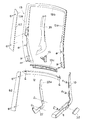
まず、図1〜図6に基づいて第1実施形態に係る椅子の概要を説明する。図1のうち(A)は椅子の斜視図で(B)は背もたれの部分的な一部破断正面図、図2は側面図、図3は背面図、図4及び図5は前方から見た分離斜視図、図6はロッキング機構を説明するための分離斜視図である。
(1). Outline of First Embodiment First, an outline of a chair according to the first embodiment will be described with reference to FIGS. 1A is a perspective view of a chair, FIG. 2B is a partially broken front view of a backrest, FIG. 2 is a side view, FIG. 3 is a rear view, and FIGS. 4 and 5 are viewed from the front. FIG. 6 is an exploded perspective view for explaining the locking mechanism.
例えば図1〜3に示すように、椅子は、主要要素として、脚支柱2(ガスシリンダ)を有する脚装置1、脚支柱2の上端に固定されたベース3、ベース3の上方に配置された座4、背もたれ5、オプション品として背もたれ5に取付けられたヘッドレスト装置6を備えている。脚1は放射状に延びる複数本の枝足7を備えており、各枝足7の先端にはキャ
スタを設けている。
For example, as shown in FIGS. 1 to 3, the chair is disposed above the
ベース3の左右両側には、左右一対の揺動フレーム8が配置されている。揺動フレーム8は、非ロッキング時に水平に近い姿勢で後傾している基部9と、その後端から立ち上がった背支柱10とから成っている。そして、揺動フレーム8は、その前端部を中心にして後傾動(回動)するように、基部9の前端部がベース3に左右長手の支軸部11で連結されている。揺動フレーム8は、例えばアルミダイキャストのような金属成形品を採用しているが、樹脂成形品でも良いし、或いは、板金製品を採用することも可能である。左右の揺動フレーム8は、基部9と背支柱10とが連接したコーナー部においてジョイントフレーム11で連結されている。
A pair of left and right swing frames 8 are arranged on the left and right sides of the
背もたれ5は、正面視略四角形のバックフレーム13にサポートシート14が張られた構成であり、バックフレーム13は、揺動フレーム10の支柱10にビスで固定されている(詳細は後述する。)。バックフレーム13は、着座者の腰部に当たる部分が側面視で最も前端となるように側面視で緩く湾曲しており、従って、サポートシート14(或いは背もたれ5)は、ランバーサポート部14aを有している。サポートシート14におけるランバーサポート部14aの左右両側部には、裏側からランバーパッド14が当たっている。なお、サポートシート14は平面視で前向き凹状に凹んでいる。また、本実施形態のサポートシート14は、縦長の疎部と密部とが左右方向に交互に配置された縦縞模様の外観を呈しており、疎部では前後に透けて見える。
The backrest 5 has a configuration the
バックフレーム13は樹脂の成形品であり、例えば図4に示すように、上下方向に長く延びる左右サイドメンバー13aと、左右サイドメンバー13aの上端に繋がったアッパーメンバー13bと、左右サイドメンバー13aの下端に繋がったロアメンバー13cとから成っている。従って、バックフレーム13は、正面視で略四角形の形態を成している。アッパーメンバー13b及びロアメンバー13cは、平面視で前向き凹状に緩く湾曲している。
The
既述のとおり、揺動フレーム10は、その前端部を中心にして後傾するようにベース3に支軸部11で連結されているが、本実施形態では、ロッキング用ばね手段として、支軸部11に内蔵したトーションバー(図示せず)を採用している。トーションバーは、その左右中間部がベース3に回転不能に保持されており、左右両端部は揺動フレーム8の前端部に固定されている。このため、揺動フレーム8は、トーションバーをねじり変形させながら後傾する。
As already mentioned, the
支軸部11はベース3の左右外側に大きく突出しており、このため揺動フレーム8もベース3のかなり外側に配置されている。但し、例えば図3(B)から理解できるように、揺動フレーム8は、座4の左右外側面よりも内側に位置している。従って、揺動フレーム8が人の歩行の邪魔になるようなことはない。
The support shaft portion 11 protrudes greatly on the left and right outer sides of the
座4は、樹脂製のインナーシェル(図示せず)とその上面に張ったクッション、及びインナーシェルを支持するアウターシェル16(図6参照)を有している。本願発明との関係は薄いので詳細は省略するが、座4のアウターシェル16はその下方に配置した中間部材17に前後位置可能に取り付けられており、中間部材の前部には前ブラケット部18が形成されていて、この前ブラケット部18とベース3とがフロントリンク20で連結されている。フロントリンク20は、ベース3に挿通した前支軸20′に回動可能に取り付けられている。フロントリンク20の上端は、前後長手の補助枠材21に連結されている。補助枠材21は中間部材17に前後スライド可能でに保持されており、かつ、補助枠材21は座4(アウターシェル19)と一体に動く。
The seat 4 has a resin inner shell (not shown), a cushion stretched on the upper surface thereof, and an outer shell 16 (see FIG. 6) for supporting the inner shell. The outer shell 16 of the seat 4 is attached to an intermediate member 17 disposed below the seat 4 so that it can be moved back and forth. The front bracket 18 is attached to the front of the intermediate member. The front bracket portion 18 and the
図4〜6に示すように、揺動フレーム10の内側面にはリアリンク22が配置されてい
る。リアリンク22は揺動フレーム8に似た側面視略L形の形態であり、起立部22aが揺動フレーム8における背支柱10の内面に沿って延びており、かつ、リアリンク22は、起立部22aの付け根よりもやや手前側の部位において枢支ピン23(図4参照)。揺動フレーム8に連結されている。リアリンク21の前端は上向きに突出しており、これが補助枠材21の後端部にリアピン24で連結されている。
As shown in FIGS. 4 to 6, a
従って、背もたれ5(及び揺動フレーム8)が後傾すると、座4は後退しつつ後傾する。揺動フレーム8のおおよそ前後中間部の内側面には、水平に対してやや後傾した姿勢のガイド長穴が空いている一方、座4が取り付けられている中間部材には、ガイド長穴にスライド自在に嵌まるガイドピン25(図5,7参照)を設けている。ガイドピン25がガイド長穴でガイドされることにより、座4は、独自に後退及び後傾することなく、揺動フレーム8との連動関係が強制されている。
Therefore, when the backrest 5 (and the swing frame 8) tilts backward , the seat 4 tilts backward while moving backward. On the inner surface of the front / rear intermediate portion of the
着座した人が背もたれ5にもたれ掛かると、リアリンク22の起立部22aも後傾するが、背支柱10に対しても相対的に後傾する。すなわち、背支柱10が後傾する割合よりも、リアリンク22の起立部22aが後傾する割合が大きい。そして、リアリンク22における起立部22aの上端部に、既述したランバーパッド15を高さ調節可能に取り付けている。従って、ロッキングに際して、ランバーパッド15は背支柱10に対して相対的に後退することになり、このため、サポートシート14はロッキングするとテンションが緩む。
When the seated person leans against the backrest 5, the standing
さて、非ロッキング状態で人がパソコン操作等の執務・作業を行う場合、その上半身は、サポートシート14のランバーサポート部14aで腰部を後ろから支えているのが好ましい。従って、非ロッキング状態では、ランバーサポート部14aは側断面視で前向き凸にかなり突出しているのが好ましい。他方、ランバーサポート部14aが大きく突出した状態のままでロッキング状態に移行すると、腰部が過度に突き上げられる虞がある。そこで本実施形態では、ロッキング時には、ランバーパッド15を背支柱10に対して相対的に後退させて、サポートシート14のテンションを緩めているのである。
Now, when a person performs work / work such as personal computer operation in a non-locking state, it is preferable that the upper body supports the lumbar part from behind by the
ヘッドレスト装置6は、バックフレーム13におけるサイドメンバー13aの左右内側面から立ち上がった左右のヘッド支柱27を有しており(図1(A)や図4では片方のヘッド支柱13bしか表示していない)、ヘッド支柱27に、ヘッドレスト28が高さ調節可能に取り付けられている。
The
ヘッド支柱27は、その下端寄りの部位を中心にして前後に回動するようにピン(或いはビン部)でサイドメンバー13aに連結されており、かつ、ヘッド支柱27の下端は、回動吸収装置29を介してリアリンク22の起立部22aに連結されている。ロッキングに際しては、ヘッド支柱27はその上部が手前に移動するように回動する。従って、着座した人は、ロッキング状態のままで頭を起こすことなくパソコンのディスプレイを楽に見ることができたり、読書に際して本を持ち上げる必要がないといった利点がある。また、回動吸収装置29にはばねが内蔵されており、ヘッド支柱27はばねに抗して後傾動させることができる。
(2).ランバーパッドの周辺部
次に、従前の図に加えて図7以下の図面も参照して、ランバーパッド15の周辺部を説明する。図7のうち(A)はバックフレーム13の側面図、(B)はランバーパッド15の平面図、(C)はランバーパッド15の正面図、図8のうち(A)は要部の分離側面図、(B)は要部の分離斜視図、図9のうち(A)は背支柱10の上部の斜視図、(B)はバックフレーム13におけるサイドメンバー13aの破断斜視図、図10は(A)は非ロッキング状態での部分側面図、(B)はロッキング状態での部分側面図、図11は図10においてランバーパッド15を少し下方にずらした状態での XI-XI視断面図である。まず、揺動フレーム8とジョイントフレーム12について説明する。
(2) Peripheral portion of lumbar pad Next, the peripheral portion of the
既述のとおり揺動フレーム8はアルミの成形品であり、例えば図9(A)に示すように、揺動フレーム8の基部9は、内側に開口した概ね樋状に形成されていてその内部に補強リブを設けている。また、揺動フレーム8の基部9のうち前後略中間部には、外向きに開口すると共にやや外側に突出した角形穴部31(図4参照)が形成されている。この角形穴部31は肘掛け装置を取り付けるためのものであり、肘掛け装置を取り付けない場合はカバー32(例えば図5参照)で塞がれている。
例えば図6に示すよう、揺動フレーム8の基部9には、リアリンク22を覆うための下インサイドカバー34を設けている。例えば図9や図11に明示するように、背支柱10は側板35と背面板36とを有している。側板35は平面視で前後方向に延びているが、背面板36は、平断面視において背もたれ5の中心に行くに従って後ろにずれるような傾斜にしており、従って、背支柱10は、平断面視において変形L形になっている。背支柱10における側板35の前端には低い内向きのフロントリブ37が形成されており、従って、側板35の内側は浅い溝状の形態を成している。そして、側板35の内側には、フロントリブ37と同じ程度の高さの補強リブ38の群を形成している。
For example, as shown in FIG. 6, the
背支柱10を変形L形に形成しているのは、側板35と背面板36とで囲われた空間にリアリンク22の起立部22aを配置するためである。リアリンク22の起立部22aは、上インサイドカバー39で覆われている。例えば図9(A)に示すように、背支柱10における背面板36の上部には、上インサイドカバー39を取り付けるためのブラケット部40を設けている。また、背支柱10における背面板36には、上下に長く延びる内向きのリアリブ41を形成している。
The reason why the
既述のとおり、ヘッド支柱27はリアリンク22の後傾動に連動して前傾動するものでり、回動吸収装置29がリアリンク22にける起立部22aの上端に連結されている。そして、ヘッドレスト装置6を取り付けない場合もあり、この場合は、例えば図11(A)に示すように、背支柱10の上端には天キャップ42が装着されている。背支柱10における背面板36の上端部内面には、天キャップ42を取り付けるための係止部43が設けられている。
As described above, the
例えば図11に示すように、バックフレーム13のサイドメンバー13aは、揺動フレーム8の背支柱10に左右外側から重なっている。サイドメンバー13aは左右外側に向けて前後幅が徐々に小さくなる略台形の断面形状であり、かつ、前面も背面も、背もたれ5の中心部に近づくほど後ろにずれるように後ろ向きに傾斜している。
For example, as shown in FIG. 11, the
バックフレーム13を構成する各メンバーの外周面は平坦面になっている。そして、図11にサイドメンバー13aを代表して明示するように、各メンバーの外側面(バックフレーム13の外周面)には溝条46が長く延びて形成されており、サポートシート14の終縁に固定された縁部材47が溝条46に嵌め込まれている。なお、縁部材47は、各メンバーの箇所ごとに分断されている。
The outer peripheral surface of each member constituting the
サポートシート14がバックフレーム13の外周面に取り付けられているため、背もたれ5の前面の面積の全体が着座面になっており、このため、肩幅の大きい人も安定的に支持される。また、バックフレーム13はサポートシート14の後ろに隠れるため(透けては見える)、恰も背もたれ5の全体がサポートシート14で構成されているかのような外観を呈しており、このため独特の美感が顕れている。
Since the
サポートシート14がバックフレーム13の外周面に取り付けられているため、背もたれ5の前面の面積の全体が着座面になっており、このため、肩幅の大きい人も安定的に支持される。また、バックフレーム13はサポートシート14の後ろに隠れるため(透けては見える)、恰も背もたれ5の全体がサポートシート14で構成されているかのような外観を呈しており、このため独特の美感が顕れている。
Since the
そして、例えば図10に示すように、サイドメンバー13aのうち背支柱10に重なる部分は内向きに開口した溝状になっており、内部には多数の補強リブ48を設けている。これは、例えば肉厚をできるだけ均等化して成形時のヒケを防止するためである。
For example, as shown in FIG. 10, a portion of the
図11に示すように、背支柱10は、ビス49とナット50とで背支柱10に締結されている。ビス49は背支柱10の側板35に内側から挿通されており、ナット50は、サイドメンバー13aに形成した前向き開口のナット穴51に嵌め込まれて回転不能に保持されている。ナット穴51は手前に開口しているので、ナット穴51はサポートシート14で隠れて殆ど視認できず、従って美感上の問題はない。サイドメンバー13aは上下2カ所の位置で背支柱10に固定しており、例えば図5では、サイドメンバー13aのビス挿入穴52を示している。
As shown in FIG. 11, the back posts 10 is fastened to the back posts 10 in the
(4).ランバーパッド
次に、ランバーパッド15を説明する。ランバーパッド15は樹脂製品であり、例えば図7に示すように、上下長手で側面視及び平面視で前向き突状に湾曲している。このため、サポートシート14は特定部位に応力が集中することなく円滑に支持されている。そして、ランバーパッド15のうち左右外端部には、リアリンク22の起立部22aに前から嵌まる溝形の受け部54が後ろ向きに突設されている。
(4) Lumber Pad Next, the
図8(B)に示すように、受け部54の内底面には山形のストッパー突起55が形成されている一方、リアリンク22の起立部22aには、ストッパー突起が嵌まる凹所56を多段に形成している。ランバーパッド15は、サポートシート14のテンションによってリアリンク22の起立部22aに押されており、このため、凹所56がごく浅くても、ランバーパッド15は下向きずれ不能に保持されている。
As shown in FIG. 8 (B), a chevron-shaped stopper projection 55 is formed on the inner bottom surface of the receiving
また、ランバーパッド15の背面には、操作部の一例として、人が指で摘まみ得る横向きの操作片57を一体に形成している。従って、椅子の使用者は、好みや体格等に応じてランバーサポート14の高さ位置を調節できる(操作片57は着座したまま後ろでで操作できる。)。図7,8に示すように、受け部54を構成する一方の板材の下端部でかつ後端部には内向きの規制爪58を形成している一方、リアリンク22における起立片22aには、規制爪58が上下動自在に移動しうる切欠き部59を形成している。
Further, on the back surface of the
切欠き部59で規制爪58の上下移動範囲が規制されることにより、ランバーパッド15の上下動ストロークが規制されると共に、ランバーパッド15は落下不能に保持されている。従って、切欠き部59と規制爪58とは、ランバーパッド15のストローク規制手段と落下防止手段との機能を果たしている。上インサイドカバー39の内面には、ランバーパッド15が後退したときに受け部63を安定的に保持するスペーサ60を配置している。
By restricting the vertical movement range of the restricting claw 58 by the notch 59, the vertical movement stroke of the
さて、図11に明示するように、正面視において、ランバーパッド15は、背支柱10と部分的に重なるように配置されており、従って、ランバーパッド15は、背もたれ5の左右端部に寄って配置されている。従って、ランバーパッド15が大きく目立つことはなくて美感に優れている。特に、椅子のバックビューにおいて、ランバーパッド15は目立たずにサポートシート14が強調されているため、シンプルな外観を呈している。また、バックフレーム13の前面は左右内側に行くに従って後ろにずれるように傾斜しているため、人のもたれ掛かりによってサポートシートが後ろに伸び変形することが許容されていると共に、サポートシート14への負担も軽減されている。
Now, as best shown in FIG. 11, Oite viewed from the front, the
また、ランバーパッド15は側面視と平面視とで湾曲していることと(特に側面視での湾曲が重要である)、ランバーパッド15が上下に長くて前面の面積が大きいこととにより、サポートシート14の狭い箇所に強い力が集中することがなくて、サポートシート14は高い耐久性を確保できる。また、ランバーパッド15は最大幅に対して上下長さが3倍程度の上下に細長い形態であるが、正面視で外端面15aは鉛直に近い形態であるのに対して、内端面は外向き凸条に緩く曲がった形状であり、正面視においも丸みを持っている。
Further, the
このような形状により、サポートシート14の形状に倣って適切な支持機能が発揮される。つまり、サポートシート14は、バックフレーム13のリアリンク22の作用によって下に行くほど平面視での湾曲の度合いは大きくなっているが、実施形態のようにランバーパッド15に正面視においても丸みを持たせると、サポートシート14が後ろ向きに湾曲することが下に行くほど容易になっているのであり、このため、サポートシート14の立体的な曲がりの形態にフィットしているのである。
With such a shape, an appropriate support function is exhibited following the shape of the
(5).第2実施形態
図12では第2実施形態を示している。この実施形態も基本的には第1実施形態と同じであり、第1実施形態との違いとしては、まず、バックフレーム13のロアメンバー13cがサイドメンバー13aとは別部材なっている点が挙げられる。また、この実施形態ではランバーパッド15は板状に形成されており、ランバーパッド15とサポートシート(図示せず)との間に、上下に長い可撓性シート62が配置されている。可撓性シート62はサイドメンバー13aにビス等で固定されているが、ランバーパッド15と一緒に上下動させても良い。
(5). Second Embodiment FIG. 12 shows a second embodiment. This embodiment is basically Ri same der the first embodiment, the difference from the first embodiment, first, the point that the
(6).その他
本願発明は、上記の実施形態の他にも様々に具体化できる。例えば、適用対象は必ずしも回転椅子に限定されるものではなく、劇場用椅子やベンチのような固定式椅子にも適用できる。敢えて述べるまでもないが、ランバーパッド15はロッキング時に後退する必要はないのであり、従って、ランバーパッドをバックフレームのサイドメンバーに上下動自在に取り付けるといったことも可能である。ランバーパッドは、例えばブロック状に形成して人が手を掛け得るように形成することも可能である。
(6). Others present invention can be in addition to various concrete than the above embodiment. For example, the application target is not necessarily limited to a rotating chair, and can be applied to a fixed chair such as a theater chair or a bench . Without even mentioned daringly Ete,
1 脚装置
3 ベース
4 座
5 背もたれ
8 揺動フレーム
10 揺動フレームの背支柱
13 バックフレーム
13a バックフレームのサイドメンバー
14 サポートシート
14a ランバーサポート部
15 ランバーパッド
54 受け部
57 操作部の一例としての操作片
DESCRIPTION OF
Claims (2)
請求項1に記載した背もたれ付き椅子。 The front surfaces of the left and right lumbar pads are in a form that curves forwardly in both a side view and a plan view,
A chair with a backrest according to claim 1.
請求項1又は2に記載した背もたれ付き椅子。 The left and right lumbar pads are vertically long,
A chair with a backrest according to claim 1 or 2.
Priority Applications (1)
| Application Number | Priority Date | Filing Date | Title |
|---|---|---|---|
| JP2014071778A JP5764233B2 (en) | 2014-03-31 | 2014-03-31 | Chair with backrest |
Applications Claiming Priority (1)
| Application Number | Priority Date | Filing Date | Title |
|---|---|---|---|
| JP2014071778A JP5764233B2 (en) | 2014-03-31 | 2014-03-31 | Chair with backrest |
Related Parent Applications (1)
| Application Number | Title | Priority Date | Filing Date |
|---|---|---|---|
| JP2008270552A Division JP5514425B2 (en) | 2008-10-21 | 2008-10-21 | Chair with backrest |
Related Child Applications (1)
| Application Number | Title | Priority Date | Filing Date |
|---|---|---|---|
| JP2015119369A Division JP6080902B2 (en) | 2015-06-12 | 2015-06-12 | Chair with backrest |
Publications (3)
| Publication Number | Publication Date |
|---|---|
| JP2014140765A JP2014140765A (en) | 2014-08-07 |
| JP2014140765A5 true JP2014140765A5 (en) | 2014-09-25 |
| JP5764233B2 JP5764233B2 (en) | 2015-08-19 |
Family
ID=51422581
Family Applications (1)
| Application Number | Title | Priority Date | Filing Date |
|---|---|---|---|
| JP2014071778A Active JP5764233B2 (en) | 2014-03-31 | 2014-03-31 | Chair with backrest |
Country Status (1)
| Country | Link |
|---|---|
| JP (1) | JP5764233B2 (en) |
Family Cites Families (2)
| Publication number | Priority date | Publication date | Assignee | Title |
|---|---|---|---|---|
| JP3986745B2 (en) * | 2000-10-16 | 2007-10-03 | コクヨ株式会社 | Chair |
| JP5116948B2 (en) * | 2005-03-31 | 2013-01-09 | 株式会社岡村製作所 | Chair backrest device |
-
2014
- 2014-03-31 JP JP2014071778A patent/JP5764233B2/en active Active
Similar Documents
| Publication | Publication Date | Title |
|---|---|---|
| JP5646725B2 (en) | Rocking chair | |
| JP6343118B2 (en) | Nestable chair | |
| JP6810107B2 (en) | Chair | |
| JP5013969B2 (en) | Rocking chair | |
| JP6262937B2 (en) | Nestable chair | |
| KR20080037029A (en) | Chair | |
| JP6270307B2 (en) | Nestable chair | |
| JP5514425B2 (en) | Chair with backrest | |
| JP5339548B2 (en) | Chair with backrest | |
| JP2007151582A (en) | Body supporting plate and chair | |
| JP6876409B2 (en) | Chair back | |
| JP6080902B2 (en) | Chair with backrest | |
| JP5451027B2 (en) | Rocking chair | |
| JP5764233B2 (en) | Chair with backrest | |
| JP2015157224A5 (en) | ||
| JP2014140765A5 (en) | ||
| JP6196438B2 (en) | Rocking chair | |
| JP5096870B2 (en) | Chair with backrest | |
| JP5571733B2 (en) | Chair | |
| JP6412300B2 (en) | Nestable chair | |
| JP7015146B2 (en) | Chair | |
| JP5530545B2 (en) | Chair with backrest | |
| JP2010099105A (en) | Chair with headrest | |
| JP6670069B2 (en) | Chair | |
| TW201519830A (en) | Support adjusting structure of chair back |