JP2014136357A - Case for electronic equipment and manufacturing method of the same - Google Patents
Case for electronic equipment and manufacturing method of the same Download PDFInfo
- Publication number
- JP2014136357A JP2014136357A JP2013005638A JP2013005638A JP2014136357A JP 2014136357 A JP2014136357 A JP 2014136357A JP 2013005638 A JP2013005638 A JP 2013005638A JP 2013005638 A JP2013005638 A JP 2013005638A JP 2014136357 A JP2014136357 A JP 2014136357A
- Authority
- JP
- Japan
- Prior art keywords
- thin plate
- prepreg thin
- prepreg
- continuous fiber
- resin
- Prior art date
- Legal status (The legal status is an assumption and is not a legal conclusion. Google has not performed a legal analysis and makes no representation as to the accuracy of the status listed.)
- Pending
Links
Images


Abstract
Description
本出願は電子機器の筐体及び該筐体の製造方法に関する。 The present application relates to a casing of an electronic device and a method for manufacturing the casing.
近年、携帯電話やスマートフォン、個人情報機器(PDA)、ノート型コンピュータ、カーナビゲーション装置等の小型電子機器が薄肉小型化されるにつれ、これらの電子機器の筐体にも肉厚が薄く軽量で、かつ高い剛性を持つ筐体部品が求められている。 In recent years, as small electronic devices such as mobile phones, smartphones, personal information devices (PDAs), notebook computers, car navigation devices have become thinner and smaller, the casings of these electronic devices are also thinner and lighter, In addition, a housing component having high rigidity is required.
一般に、薄肉高強度の筐体部品を製造する方法として以の方法が知られている。
(1)ガラス繊維や炭素繊維を充填した繊維強化熱可塑性樹脂を射出成形する方法
(2)アルミニウム合金やマグネシウム合金の圧延板をプレス加工する方法
(3)アルミニウム合金やマグネシウム合金を射出成形(ダイカスト法、チクソモールド法など)する方法
(4)金属板や繊維強化樹脂(以後FRPという)の板とをインサート成形により一体成形する方法
In general, the following methods are known as methods for producing thin-walled and high-strength casing parts.
(1) Method of injection molding a fiber reinforced thermoplastic resin filled with glass fiber or carbon fiber (2) Method of pressing a rolled plate of aluminum alloy or magnesium alloy (3) Injection molding (die casting of aluminum alloy or magnesium alloy (4) Method of integrally forming a metal plate or a fiber reinforced resin (hereinafter referred to as FRP) plate by insert molding
このうち、FRPの板をインサート成形する場合、通常FRPは熱硬化性樹脂のマトリクス(母材)を持つため、熱可塑性樹脂とは強固に接着しなかった。このため、FRPを熱可塑性樹脂と一体化するために、以下のような方法が行われていた。
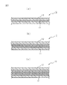
(A)図1(a)に示すようにFRP製の部品2を熱可塑性樹脂製の薄板基材1にネジ3で接合する。
(B)図1(b)に示すようにFRP製の部品2を熱可塑性樹脂製の薄板基材1に接着剤4を用いて接合する。
(C)図1(c)に示すように、熱可塑性樹脂製の薄板基材1に貫通孔5を設け、成形時にモールド樹脂14が貫通孔5を通じて薄板基材1の裏面に回り込むようなマクロな嵌合構造を設けて接合する。この方法に使用するモールド樹脂14は熱硬化性FRPであり、固まると熱が加わっても溶けない性質を持つ。
Among these, when FRP plates are insert-molded, the FRP usually has a thermosetting resin matrix (base material), and thus it was not firmly bonded to the thermoplastic resin. For this reason, in order to integrate FRP with a thermoplastic resin, the following method has been performed.
(A) As shown in FIG. 1A, an
(B) As shown in FIG. 1B, the
(C) As shown in FIG. 1C, a macro in which a
このため、せっかくの薄型製品の外観に図1(c)に示すような段形状が発生したり、図1(a)に示すようにネジ3が熱可塑性樹脂製の薄板基材1の表面に露出して外観が損なわれるなどの弊害があった。
For this reason, a stepped shape as shown in FIG. 1 (c) occurs in the appearance of a precious thin product, or as shown in FIG. 1 (a), the screw 3 is formed on the surface of the
これを解決する方法として、特許文献1及び特許文献2に開示の技術が知られている。これらはいずれもFRP基材の表面に接着剤となる低融点のポリアミド樹脂をコーティングすることにより、より高融点のモールド樹脂と接着して一体化する技術である。これらの技術を使用すれば、段差の無いよりスマートな製品外観が得られたり、より強固な接着が得られる利点がある。
As a method for solving this, the techniques disclosed in
ところが、特許文献1及び特許文献2に開示の技術では、モールド樹脂に使用する樹脂材料の相溶性の問題から、ポリアミド樹脂以外のモールド樹脂が使用できない制限があり、耐熱性に優れた樹脂が使用できなかった。また、ポリアミド樹脂は吸水によって基材剛性が低下するなどの課題があった。
However, in the techniques disclosed in
1つの側面では、本出願は、熱可塑性樹脂をマトリクスとするプリプレグの薄板に、様々な樹脂材料を射出して強固に一体成形でき、外観性の向上、薄肉軽量及び高信頼性を実現可能な電子機器の筐体及び該筐体の製造方法を提供することを目的とする。 In one aspect, the present application is capable of injecting various resin materials onto a prepreg thin plate made of a thermoplastic resin as a matrix and integrally forming it, thereby realizing improved appearance, thin-walled weight and high reliability. It is an object of the present invention to provide a casing of an electronic device and a method for manufacturing the casing.
実施形態の一観点によれば、連続繊維を熱可塑性樹脂でコーティングしたプリプレグ薄板を備え、プリプレグ薄板の少なくとも一方の面に、連続繊維が凸状または凹状の形態で露出しており、連続繊維が凸状または凹状の形態で露出しているプリプレグ薄板の表面を覆うように、強化繊維を含む樹脂材料が積層されて形成されたことを特徴とする電子機器の筐体が提供される。 According to one aspect of the embodiment, a prepreg thin plate in which continuous fibers are coated with a thermoplastic resin is provided, and the continuous fibers are exposed in a convex or concave form on at least one surface of the prepreg thin plate, There is provided a casing for an electronic device characterized in that a resin material containing reinforcing fibers is laminated so as to cover the surface of a prepreg thin plate exposed in a convex or concave form.
実施形態の他の観点によれば、連続繊維を熱可塑性樹脂でコーティングしてプリプレグ薄板を作り、プレス面の少なくとも1箇所に微細凹凸を備えるプレス金型によりプリプレグ薄板を両面から圧縮し、圧縮時に、微細凹凸によってプリプレグ薄板を三次元形状に変形させると共に、プリプレグ薄板の内部にある連続繊維を凹凸形状に変形させ、プリプレグ薄板の変形部分の表層部分に位置する熱可塑性樹脂を切削加工によって除去して、連続繊維の少なくとも一部をプリプレグ薄板の表層部分に露出させ、連続繊維の露出部を含むプリプレグ薄板の表面に、強化繊維を含む樹脂材料を積層することによって電子機器の筐体を製造する方法が提供される。 According to another aspect of the embodiment, a continuous fiber is coated with a thermoplastic resin to make a prepreg thin plate, and the prepreg thin plate is compressed from both sides by a press die having fine irregularities at least at one place on the press surface. The prepreg thin plate is deformed into a three-dimensional shape by fine unevenness, and the continuous fibers inside the prepreg thin plate are deformed into an uneven shape, and the thermoplastic resin located in the surface layer portion of the deformed portion of the prepreg thin plate is removed by cutting. Then, at least a part of the continuous fiber is exposed on the surface layer portion of the prepreg thin plate, and a resin material containing reinforcing fiber is laminated on the surface of the prepreg thin plate including the exposed portion of the continuous fiber to manufacture a casing of the electronic device. A method is provided.
以下、添付図面を用いて本出願の実施の形態を、具体的な実施例に基づいて詳細に説明する。 Hereinafter, embodiments of the present application will be described in detail based on specific examples with reference to the accompanying drawings.
図2(a)は、一層の連続繊維11を熱可塑性樹脂12でコーティングした繊維強化樹脂の薄板10の断面図である。このような繊維強化樹脂の薄板10は熱可塑性プリプレグと呼ばれる。熱可塑性樹脂12でコーティングする連続繊維11の層は一層に限定されるものではなく、繊維強化樹脂の薄板10に必要な強度に応じて層の数を増やすことができる。図2(b)は、二層の連続繊維11が熱可塑性樹脂12でコーティングされた繊維強化樹脂の薄板10を示すものであり、図2(c)は三層の連続繊維11が熱可塑性樹脂12でコーティングされた繊維強化樹脂の薄板10を示すものである。以後繊維強化樹脂の薄板10はプリプレグ薄板10と言う。
FIG. 2A is a cross-sectional view of a
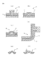
本出願では、図2(a)〜(c)等に示されるプリプレグ薄板10に内蔵される連続繊維11を、プレス金型を用いて変形させる。この工程を、図2(a)に示した一層の連続繊維11を熱可塑性樹脂12でコーティングしたプリプレグ薄板10を用いた場合について図3により説明する。
In the present application, the
図3(a)は、図2(a)に示したプリプレグ薄板10を、プレス金型20に入れてプレスする工程を示すものである。プレス金型20は雄金型21と雌金型22を備えており、プリプレグ薄板10は雌金型22の凹部24の中に載置される。プレス金型20の雄金型21には凹部24内に挿入される凸部23が設けられている。そして、雄金型21の凸部23と雌金型22の凹部24のB部、D部及びF部には、プリプレグ薄板10にある連続繊維11を三次元形状に変形させるための凹部25,26,27が設けられている。
FIG. 3A shows a process of pressing the prepreg
図3(b)は図3(a)に示したプレス金型20が閉じられた時の、プレス金型20のB部近傍を部分的に拡大して示すものである。図3(b)に示す状態では、プレス金型20の雄金型21と雌金型22との間に圧力は加わっていない。雄金型21と雌金型22との間に圧力を加えると、凹部25内に熱可塑性樹脂12が入り込み、熱可塑性樹脂12の移動により連続繊維11も凹部25内に入る。そして、凹部25の深さを大きくしておくと、連続繊維11は凹部25内に入る過程で破断し、図3(c)に示す状態になる。凹部の寸法及び深さと連続繊維がプレス時に破断するか否かのデータについては後述する。
FIG. 3B is a partially enlarged view of the vicinity of portion B of the press die 20 when the press die 20 shown in FIG. 3A is closed. In the state shown in FIG. 3B, no pressure is applied between the
図3(d)は図3(a)に示したプレス金型20が閉じられた時の、プレス金型20のD部近傍を部分的に拡大して示すものである。図3(d)に示す状態では、プレス金型20の雄金型21と雌金型22との間に圧力は加わっていない。雄金型21と雌金型22との間に圧力を加えると、凹部26内に熱可塑性樹脂12が入り込み、熱可塑性樹脂12の移動により連続繊維11も凹部26内に入る。凹部26の深さはあまり大きくないので、連続繊維11は凹部26内に入る過程では破断せず、図3(e)に示すように、窪んだ状態(三次元形状に変形した状態)になる。
FIG. 3D shows a partially enlarged view of the vicinity of the D portion of the press die 20 when the press die 20 shown in FIG. 3A is closed. In the state shown in FIG. 3D, no pressure is applied between the
図3(f)は図3(a)に示したプレス金型20が閉じられた時の、プレス金型20のF部近傍を部分的に拡大して示すものである。図3(f)に示す状態では、プレス金型20の雄金型21と雌金型22との間に圧力は加わっていない。雄金型21と雌金型22との間に圧力を加えると、凹部27内に熱可塑性樹脂12が入り込み、熱可塑性樹脂12の移動により連続繊維11も凹部27内に入る。凹部27の深さもあまり大きくないので、連続繊維11は凹部27内に入る過程では破断せず、図3(g)に示すように、窪んだ状態になる。
FIG. 3 (f) shows a partially enlarged view of the vicinity of the F portion of the press die 20 when the press die 20 shown in FIG. 3 (a) is closed. In the state shown in FIG. 3 (f), no pressure is applied between the
図4(a)は、図2(b)に示したプリプレグ薄板10をプレス金型20に入れてプレスした後の、プレス金型20のB部に対応する部分のプリプレグ薄板10を示すものである。この実施例に示すプリプレグ薄板10は、一層目の連続繊維11が破断されて変形しているが、二層目の連続繊維11には変形が生じていない。プレス金型20に設ける凹部のサイズにより、一層目の連続繊維11だけをこのように変形させることが可能である。
FIG. 4A shows the prepreg
図4(b)は、図2(b)に示したプリプレグ薄板10をプレス金型20に入れてプレスした後の、プレス金型20のF部に対応する部分のプリプレグ薄板10を示すものである。この実施例に示すプリプレグ薄板10は、一層目の連続繊維11が上側に凸になるように変形しているが、二層目の連続繊維11には変形が生じていない。プレス金型20に設ける凹部のサイズにより、一層目の連続繊維11だけをこのように変形させることが可能である。
FIG. 4B shows the prepreg
図4(c)は、図2(b)に示したプリプレグ薄板10をプレス金型20に入れてプレスした後の、同じくプレス金型20のF部に対応する部分のプリプレグ薄板10を示すものである。この実施例に示すプリプレグ薄板10は、一層目の連続繊維11が上側に凸のドーム形状になるように変形しているが、二層目の連続繊維11には変形が生じていない。プレス金型20に設ける凹部のサイズにより、一層目の連続繊維11だけをドーム形状に変形させることが可能である。
FIG. 4C shows the prepreg
図4(d)は図2(b)に示したプリプレグ薄板10を、プレス金型20の形状によりバスタブ状に成形すると共に、プレス金型20に設けたスライド金型(図示省略)により、プリプレグ薄板10の外側の面に連続繊維11の変形部を設けた実施例である。このように、プレス金型20によって連続繊維11を変形させる部分は、プリプレグ薄板10の上下どちらにも設けることができ、プリプレグ薄板10をバスタブ状に成形した場合にはプリプレグ薄板10の外側の面にも設けることが可能である。
4 (d) shows the prepreg
図4(e)は、プリプレグ薄板10に内蔵される連続繊維11の変形前の状態を示すものである。連続繊維11には縦糸と横糸があり、連続繊維11は縦糸と横糸によって糸と糸の間の隙間が殆ど無い状態で編みこまれている。図4(f)はプレス金型20によって連続繊維11が変形した後の連続繊維11の縦糸と横糸の状態を示すものである。プレス金型20によって連続繊維11が変形すると、図4(f)に示すように、糸と糸の間に隙間Sができる。よって、連続繊維11が変形した部分の表層の熱可塑性樹脂12を除去して連続繊維11を露出させれば、この上に強化繊維を含む樹脂材料を積層すると、樹脂材料が連続繊維11の隙間に入り込むので、連続繊維11と強化繊維を含む樹脂材料の結合が強まる。
FIG. 4 (e) shows a state before deformation of the
以上のように、プリプレグ薄板10は予め筐体の外形形状に加工すると同時に、後にモールド樹脂を積層する部分の連続繊維11に微細な凹凸形状を付与しておく。これによりモールド樹脂と連続繊維11との接合部分の面積が増加するとともに、アンカー効果による結合力が向上する。
As described above, the prepreg
連続繊維11が変形した部分の表層の熱可塑性樹脂12を除去するには、グラインダ等で削る方法や、図5(a)に示すようにレーザ装置30からのレーザ光を用いたレーザ切削による方法がある。レーザ装置30は、プレス金型20に設けられた凹部の位置に合わせて移動させることができるので、連続繊維11が変形した部分の表層の熱可塑性樹脂12を正確に除去することが可能である。
In order to remove the
このレーザ装置30を使用すれば、連続繊維11が変形した部分の表層の熱可塑性樹脂12を色々な形状に削除することが可能である。図5(b)は図4(b)に示したプリプレグ薄板10における連続繊維11の凸状に変形した部分Tの上部に位置する熱可塑性樹脂12を全て除去した実施例を示している。また、図5(c)は図4(b)に示したプリプレグ薄板10における連続繊維11の凸状に変形した部分Tの上部に位置する熱可塑性樹脂12を、部分的に除去して所定のパターンを形成した実施例を示している。更に、図5(d)は図4(b)に示したプリプレグ薄板10における連続繊維11の凸状に変形した部分Tの頂面の上部に位置する熱可塑性樹脂12を部分的に除去して露出させると共に、露出部の周囲に壁部Wを形成した実施例を示している。
If this
図6(a)は、連続繊維11の変形部分の表層にある熱可塑性樹脂12が部分的に除去されたプリプレグ薄板10をモールド金型40内に設置して、射出成形機50により強化繊維を含む樹脂材料を射出するインサート成形を説明するものである。モールド金型40には、雄金型41、雌金型42、樹脂流路45が設けられた凸部43、プリプレグ薄板10をセットする凹部44及びプリプレグ薄板10の内側に強化繊維を含む樹脂材料を積層するためのキャビティ46がある。キャビティ46はプリプレグ薄板10の内側に形成する平坦部やボス部及びリブ部に対応して設けられる。
FIG. 6A shows that the prepreg
図6(b)は表層の熱可塑性樹脂12が部分的に除去されたプリプレグ薄板10に、モールド金型40内で強化繊維13を含むモールド樹脂14を射出した時のモールド金型40内の強化繊維13を含むモールド樹脂14の挙動を説明するものである。モールド金型40内のキャビティ46に流れ込んだ強化繊維13を含むモールド樹脂14は、連続繊維11の変形部分に達すると、前述のように連続繊維11の変形部分に絡みついて強固に結合する。
FIG. 6B shows the reinforcement in the
即ち、プリプレグ薄板10とモールド樹脂14とを接合する際には、モールド樹脂14が、表層樹脂(熱可塑性樹脂12)を除去した連続繊維11の隙間S(図4(f)参照)に含浸し、同時にモールド樹脂14中の強化繊維13が連続繊維11の隙間Sに入り込むことで強固な接着が得られる。プリプレグ薄板10のマトリクスに耐熱性が高い樹脂を使用すれば、一部をプリプレグ薄板10の表面に残存させることで、アンカー効果を付与することもできる。このため従来技術のようにプリプレグ薄板10とモールド樹脂14との組み合わせが制限されない。
That is, when the prepreg
これに対して、図6(c)に示すように、熱可塑性樹脂12の一部を除去して連続繊維11を露出させただけのプリプレグ薄板10には、露出部分の連続繊維11に隙間Sがない。従って、モールド金型40内に強化繊維13を含むモールド樹脂14を射出した場合でも、強化繊維13を含むモールド樹脂14が連続繊維11に強固に結合しない。この結果、プリプレグ薄板10から強化繊維13を含むモールド樹脂14が剥れ易い。
On the other hand, as shown in FIG. 6C, the prepreg
連続繊維11の変形部分の表層にある熱可塑性樹脂12が部分的に除去されたプリプレグ薄板10に強化繊維13を含むモールド樹脂14を積層する方法は前述のインサート成形以外にもある。例えば、トランスファー成形、真空成形や、ブロー成形等を、インサート成形の代わりに行うことが可能である。
There is a method of laminating the
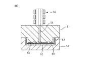
図7は、表層樹脂が部分的に除去されたプリプレグ薄板10に、トランスファー成形によって強化繊維を含む樹脂材料を積層する工程を示すものである。トランスファー成形は、射出成形と同様に繊維を露出したプリプレグ薄板10を雌金型52の凹部54に設置し、雄金型51を取り付けた状態で、溶融樹脂を樹脂流路55を通じて金型内のキャビティに56移送して硬化するものである。53は雄金型51の凸部である。トランスファー成形は、射出成形に比較して、バリ処理が必須のため手軽さはないが、熱硬化性樹脂による強化層や付加部品を成形できる。
FIG. 7 shows a step of laminating a resin material containing reinforcing fibers by transfer molding on the prepreg
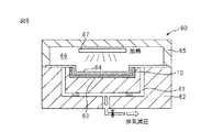
また、図8は、表層樹脂が部分的に除去されたプリプレグ薄板10に、真空成形によって強化繊維を含む樹脂材料を積層する真空成形機60を示すものである。真空成形(圧空成形)では、排気通路61が設けられた成形台62にある凹部63に繊維を露出したプリプレグ薄板10がまず嵌めこまれる。その上に強化繊維を含む樹脂材料で作られた樹脂シート64が設置される。成形台62の上にカバー65が、成形台62に対して気密に取り付けられる。カバー65には内部空間66があり、この内部空間66にヒータ67がシート64に対向して設置されている。ヒータ67によって樹脂シート64が加熱されて樹脂シート64が軟化すると、排気通路61が図示しない減圧手段に接続され、空圧または吸引により樹脂シート64がプリプレグ薄板10に押し付けられて一体化される。主に筐体の内外面に被覆層を形成したり部分的に転写することで、装飾部および、より薄肉の付加部品を形成できる。
FIG. 8 shows a
更に、図9は、表層樹脂が部分的に除去されたプリプレグ薄板10に、ブロー成形によって強化繊維を含む樹脂材料を積層するブロー成形機70を示すものである。ブロー成形機70には上金型71と下金型72があり、上金型71と下金型72の間の内部空間73に中空形状に仕上げられたプリプレグ薄板10が嵌め込まれる。そして、中空形状のプリプレグ薄板10の内部に樹脂シートがパリソン74として挿入され、吹き込み口75から高圧の熱風が吹き込まれてパリソン74がブローされる。ブローによってパリソン74が膨らみ、プリプレグ薄板10の内周面に押し付けられて一体化する。ブロー成形では、中空部品に継ぎ目のない被覆層が形成される。
Furthermore, FIG. 9 shows a
図10は、表層樹脂が部分的に除去されたプリプレグ薄板10に、強化繊維を含む樹脂材料が積層された造られた電子機器の筐体15を示すものである。電子機器の筐体15はバスタブ状であり、内部にボス16やリブ17が形成されている。そして、図11(a)は図10のX部の部分拡大断面図、図10(b)は図10のY部の部分拡大断面図、図10(c)は図10のZ部の部分拡大断面図を示している。これらの図から、連続繊維11の変形部分に強化繊維13を含むモールド樹脂14が強固に結合していることが分かる。
FIG. 10 shows a
ここで、以上説明した実施例の具体的な実現例を説明する。連続繊維11には炭素繊維(CF)が使用でき、例えば、t=0.2mmの平織CFクロスを用いる。熱可塑性樹脂12にはt=0.25mmのポリエーテルイミド(PEI)フィルムをマトリクス樹脂として使用できる。そして、図2(b)に示す二層の連続繊維(炭素繊維シート)11を三層の熱可塑性樹脂12でコーティングしてプリプレグ薄板10を製作すると、70mm×100mm、t=0.6mmのサイズのプリプレグ薄板10となった。
Here, a specific implementation example of the embodiment described above will be described. Carbon fiber (CF) can be used for the
プレス金型20としては小型プレス機を使用し、加工条件は、加熱温度280°C、ゲージ圧15MPaとした。また、図10に示したバスタブ形状の電子機器の筐体15は、50×90mmの底面を持ち、側壁の高さを5mmとした。そして、内部に設けたボス16は直径1mmで高さ1mmに形成でき、リブ17は幅1mm、長さ40mm、高さ2mmに形成することができた。
A small press machine was used as the press die 20, and the processing conditions were a heating temperature of 280 ° C. and a gauge pressure of 15 MPa. Further, the
プレス金型の雄金型または雌金型に加工した凹部の形状は、断面が円の円形穴または断面が長方形の角穴とした。そして、円形穴の直径と深さ、角穴の縦横の長さと深さを変えることにより、連続繊維を破断させずに変形させる、或いは破断させて変形させることができた。以下に円形穴と角穴の寸法と連続繊維の破断の有無のデータを示す。なお、プレス金型の雄金型または雌金型に設ける凹凸のサイズに制限は無いが、高低差が0.5mm〜1mm程度の凹凸であれば、連続繊維11が炭素繊維であってもガラス繊維であっても破断することはない。
The shape of the recess processed into the male mold or female mold of the press mold was a circular hole with a circular cross section or a square hole with a rectangular cross section. By changing the diameter and depth of the circular hole and the length and depth of the square hole, the continuous fiber could be deformed without breaking, or it could be broken and deformed. The data of the size of a circular hole and a square hole, and the presence or absence of the fracture | rupture of continuous fiber are shown below. There is no limitation on the size of the unevenness provided in the male die or female die of the press die, but if the unevenness is about 0.5 mm to 1 mm in height, glass is used even if the
(1)円形穴
直径10mmで深さ0.5mm:連続繊維に破断なし
直径10mmで深さ1.0mm:連続繊維に破断なし
直径10mmで深さ1.5mm:連続繊維に破断あり
直径1mmで深さ0.5mm:連続繊維に破断なし
直径1mmで深さ1.0mm:連続繊維に破断あり
(2)角穴
2mm×5mmで深さ0.5mm:連続繊維に破断なし
2mm×5mmで深さ1.0mm:連続繊維に破断なし
2mm×5mmで深さ1.5mm:連続繊維に破断あり
0.5mm×5mmで深さ0.5mm:連続繊維に破断なし
0.5mm×5mmで深さ1.0mm:連続繊維に破断あり
(1)
レーザ装置30としてはレーザー加工機を使用し、照射エネルギーを40Jとし、FRP板面に平行方向に走査を繰り返して熱可塑性樹脂を除去した。インサート成型は射出成形機にモールド樹脂としてポリフェニレンサルファイド(ガラス繊維30%)を使用し、樹脂温度280℃、金型温度130℃、射出速度20mm/sとした。
As the
以上のようにして製造した電子機器の筐体と従来構成の電子機器の筐体において、形成したボス部およびリブ部に対して引張試験を万能試験機を用いて行ったところ、下記の接着力を確認した。
(1)連続繊維を熱可塑性樹脂でコーティングしただけのプリプレグ薄板では、10kgf/cmであった。
(2)連続繊維を熱可塑性樹脂でコーティングし、プレス加工は行わずに表層にある熱可塑性樹脂を除去して連続繊維を除去したプリプレグ薄板では、70kgf/cmであった。
(3)連続繊維を熱可塑性樹脂でコーティングし、プレス加工を行って連続繊維に凹凸を形成し、微細凹凸の表層樹脂を除去したサンプルでは、120kgf/cm2であり、FRP板が破壊した。
When the tensile test was performed on the formed boss part and rib part using the universal testing machine in the casing of the electronic device manufactured as described above and the casing of the electronic device having the conventional configuration, the following adhesive strength was obtained. It was confirmed.
(1) In a prepreg thin plate in which continuous fibers were simply coated with a thermoplastic resin, it was 10 kgf / cm.
(2) In the prepreg thin plate in which the continuous fibers were removed by coating the continuous fibers with the thermoplastic resin and removing the thermoplastic resin on the surface layer without performing the pressing process, it was 70 kgf / cm.
(3) In the sample in which continuous fibers were coated with a thermoplastic resin, pressed to form irregularities on the continuous fibers, and the surface resin with fine irregularities was removed, the sample was 120 kgf / cm2, and the FRP plate was broken.
このように本出願によれば、プリプレグ薄板をプレス金型で圧縮した後、レーザー切削などの切削加工によりプレプリグ薄板の連続繊維が変形した部分の表層の熱可塑性樹脂を除去し、連続繊維層を露出させた状態でインサート成形して電子機器の筐体を製造する。この工程によって製造された電子機器の筐体は、プリプレグ薄板とモールド樹脂とが強固に一体化した軽量薄型で意匠性に優れた電子機器の筐体となる。 Thus, according to the present application, after compressing the prepreg thin plate with a press die, the thermoplastic resin on the surface layer where the continuous fibers of the prepreg thin plate are deformed by cutting such as laser cutting is removed, and the continuous fiber layer is removed. The housing of the electronic device is manufactured by insert molding in the exposed state. The casing of the electronic device manufactured by this process is a lightweight and thin casing of an electronic device excellent in design, in which the prepreg thin plate and the mold resin are firmly integrated.
以上、本出願を特にその好ましい実施の形態を参照して詳細に説明した。本出願の容易な理解のために、本出願の具体的な形態を以下に付記する。 The present application has been described in detail with particular reference to preferred embodiments thereof. For easy understanding of the present application, specific forms of the present application are appended below.
(付記1) 連続繊維を熱可塑性樹脂でコーティングしたプリプレグ薄板をマトリクスとし、
前記プリプレグ薄板の少なくとも一方の面に、前記連続繊維が凸状または凹状の形態で露出しており、
前記連続繊維が凸状または凹状の形態で露出している前記プリプレグ薄板の表面を覆うように、強化繊維を含む樹脂材料が積層されて形成されたことを特徴とする電子機器の筐体。
(付記2) 前記連続繊維の凸状の形態は、前記連続繊維が破断されて折れ曲がった形態であることを特徴とする付記1に記載の電子機器の筐体。
(付記3) 前記連続繊維の凸状の形態は、前記連続繊維が台形状に盛り上がった形態であることを特徴とする付記1に記載の電子機器の筐体。
(付記4) 前記連続繊維の凸状の形態は、前記連続繊維がドーム状に盛り上がった形態であることを特徴とする付記1に記載の電子機器の筐体。
(付記5) 前記プリプレグ薄板が複数層の連続繊維に対して前記熱可塑性樹脂がコーティングされて形成されたものであることを特徴とする付記1から4の何れかに記載の電子機器の筐体。
(Supplementary note 1) A prepreg thin plate with continuous fibers coated with a thermoplastic resin is used as a matrix
The continuous fiber is exposed in a convex or concave form on at least one surface of the prepreg thin plate,
A housing for an electronic device, wherein a resin material containing reinforcing fibers is laminated so as to cover a surface of the prepreg thin plate in which the continuous fibers are exposed in a convex or concave shape.
(Additional remark 2) The convex form of the said continuous fiber is a form where the said continuous fiber was fractured | ruptured and bent, The housing | casing of the electronic device of
(Additional remark 3) The convex form of the said continuous fiber is a form in which the said continuous fiber rose to the trapezoid shape, The housing | casing of the electronic device of
(Additional remark 4) The convex form of the said continuous fiber is a form which the said continuous fiber raised in the dome shape, The housing | casing of the electronic device of
(Supplementary note 5) The electronic device casing according to any one of
(付記6) 連続繊維を熱可塑性樹脂でコーティングしてプリプレグ薄板を作り、
プレス面の少なくとも1箇所に微細凹凸を備えるプレス金型により前記プリプレグ薄板を両面から圧縮し、
前記圧縮時に、前記微細凹凸によって前記プリプレグ薄板を三次元形状に変形させると共に、前記プリプレグ薄板の内部にある前記連続繊維を凹凸形状に変形させ、
前記プリプレグ薄板の変形部分の表層部分に位置する前記熱可塑性樹脂を切削加工によって除去して、前記連続繊維の少なくとも一部を前記プリプレグ薄板の表層部分に露出させ、
前記連続繊維の露出部を含む前記プリプレグ薄板の表面に、強化繊維を含む樹脂材料を積層することによって電子機器の筐体を製造する方法。
(付記7) 前記連続繊維の凸状の形態は、前記連続繊維が破断されて折れ曲がった形態であることを特徴とする付記6に記載の電子機器の筐体の製造方法。
(付記8) 前記連続繊維の凸状の形態は、前記連続繊維が台形状に盛り上がった形態であることを特徴とする付記6に記載の電子機器の筐体の製造方法。
(付記9) 前記連続繊維の凸状の形態は、前記連続繊維がドーム状に盛り上がった形態であることを特徴とする付記6に記載の電子機器の筐体の製造方法。
(付記10) 前記切削加工により、前記凸状の前記連続繊維の上面に位置する前記熱可塑性樹脂を全て除去することを特徴とする付記8または9に記載の電子機器の筐体の製造方法。
(Appendix 6) A prepreg sheet is made by coating continuous fibers with a thermoplastic resin.
Compress the prepreg thin plate from both sides with a press die having fine irregularities at least at one place on the press surface,
During the compression, the prepreg thin plate is deformed into a three-dimensional shape by the fine unevenness, and the continuous fibers in the prepreg thin plate are deformed into an uneven shape,
Removing the thermoplastic resin located in the surface layer portion of the deformed portion of the prepreg thin plate by cutting, exposing at least a part of the continuous fiber to the surface layer portion of the prepreg thin plate,
A method of manufacturing a casing of an electronic device by laminating a resin material containing reinforcing fibers on the surface of the prepreg thin plate including the exposed portion of the continuous fibers.
(Additional remark 7) The convex form of the said continuous fiber is a form which the said continuous fiber was fractured | ruptured and bent, The manufacturing method of the housing | casing of the electronic device of Additional remark 6 characterized by the above-mentioned.
(Additional remark 8) The convex form of the said continuous fiber is a form in which the said continuous fiber rose in the trapezoid shape, The manufacturing method of the housing | casing of the electronic device of Claim 6 characterized by the above-mentioned.
(Additional remark 9) The convex form of the said continuous fiber is a form which the said continuous fiber raised in the dome shape, The manufacturing method of the housing | casing of the electronic device of Additional remark 6 characterized by the above-mentioned.
(Additional remark 10) The manufacturing method of the housing | casing of the electronic device of Additional remark 8 or 9 characterized by removing all the said thermoplastic resins located in the upper surface of the said convex continuous fiber by the said cutting process.
(付記11) 前記切削加工により、前記台形状に盛り上がった凸状の前記連続繊維の上面に位置する前記熱可塑性樹脂を部分的に除去して所定のパターンを形成することを特徴とする付記8に記載の電子機器の筐体の製造方法。
(付記12) 前記切削加工がレーザ切削であることを特徴とする付記6から11の何れかに記載の電子機器の筐体の製造方法。
(付記13) 前記強化繊維を含む樹脂材料を前記繊維強化樹脂の上に積層する工程が前記プリプレグ薄板を収容する金型と、射出成形機によって行われることを特徴とする付記6から11の何れかに記載の電子機器の筐体の製造方法。
(Additional remark 11) The said thermoplastic resin located on the upper surface of the convex-shaped continuous fiber which rose to the trapezoid shape by said cutting is partially removed, and a predetermined pattern is formed. The manufacturing method of the housing | casing of the electronic device of description.
(Additional remark 12) The said cutting is laser cutting, The manufacturing method of the housing | casing of the electronic device in any one of Additional remark 6-11 characterized by the above-mentioned.
(Supplementary note 13) Any one of Supplementary notes 6 to 11, wherein the step of laminating the resin material containing the reinforced fiber on the fiber reinforced resin is performed by a mold accommodating the prepreg thin plate and an injection molding machine. A method for manufacturing a casing of the electronic device according to
10 繊維強化樹脂の薄板(プリプレグ薄板)
11 連続繊維
12 熱可塑性樹脂
13 強化繊維
14 樹脂材料(モールド樹脂)
20 プレス金型
25〜27 凹部
30 レーザ装置
40 モールド金型
50 射出成形機
10 Fiber reinforced resin sheet (prepreg sheet)
11
20 Press Die 25-27
Claims (5)
前記プリプレグ薄板の少なくとも一方の面に、前記連続繊維が凸状または凹状の形態で露出しており、
前記連続繊維が凸状または凹状の形態で露出している前記プリプレグ薄板の表面を覆うように、強化繊維を含む樹脂材料が積層されて形成されたことを特徴とする電子機器の筐体。 A prepreg thin plate in which continuous fibers are coated with a thermoplastic resin is used as a matrix.
The continuous fiber is exposed in a convex or concave form on at least one surface of the prepreg thin plate,
A housing for an electronic device, wherein a resin material containing reinforcing fibers is laminated so as to cover a surface of the prepreg thin plate in which the continuous fibers are exposed in a convex or concave shape.
プレス面の少なくとも1箇所に微細凹凸を備えるプレス金型により前記プリプレグ薄板を両面から圧縮し、
前記圧縮時に、前記微細凹凸によって前記プリプレグ薄板を三次元形状に変形させると共に、前記プリプレグ薄板の内部にある前記連続繊維を凹凸形状に変形させ、
前記プリプレグ薄板の変形部分の表層部分に位置する前記熱可塑性樹脂を切削加工によって除去して、前記連続繊維の少なくとも一部を前記プリプレグ薄板の表層部分に露出させ、
前記連続繊維の露出部を含む前記プリプレグ薄板の表面に、強化繊維を含む樹脂材料を積層することによって電子機器の筐体を製造する方法。 A continuous fiber is coated with a thermoplastic resin to make a prepreg sheet,
Compress the prepreg thin plate from both sides with a press die having fine irregularities in at least one place on the press surface,
During the compression, the prepreg thin plate is deformed into a three-dimensional shape by the fine unevenness, and the continuous fibers in the prepreg thin plate are deformed into an uneven shape,
Removing the thermoplastic resin located in the surface layer portion of the deformed portion of the prepreg thin plate by cutting, exposing at least a part of the continuous fiber to the surface layer portion of the prepreg thin plate,
A method of manufacturing a casing of an electronic device by laminating a resin material containing reinforcing fibers on the surface of the prepreg thin plate including the exposed portion of the continuous fibers.
Priority Applications (1)
| Application Number | Priority Date | Filing Date | Title |
|---|---|---|---|
| JP2013005638A JP2014136357A (en) | 2013-01-16 | 2013-01-16 | Case for electronic equipment and manufacturing method of the same |
Applications Claiming Priority (1)
| Application Number | Priority Date | Filing Date | Title |
|---|---|---|---|
| JP2013005638A JP2014136357A (en) | 2013-01-16 | 2013-01-16 | Case for electronic equipment and manufacturing method of the same |
Publications (1)
| Publication Number | Publication Date |
|---|---|
| JP2014136357A true JP2014136357A (en) | 2014-07-28 |
Family
ID=51414155
Family Applications (1)
| Application Number | Title | Priority Date | Filing Date |
|---|---|---|---|
| JP2013005638A Pending JP2014136357A (en) | 2013-01-16 | 2013-01-16 | Case for electronic equipment and manufacturing method of the same |
Country Status (1)
| Country | Link |
|---|---|
| JP (1) | JP2014136357A (en) |
Cited By (5)
| Publication number | Priority date | Publication date | Assignee | Title |
|---|---|---|---|---|
| WO2016051574A1 (en) * | 2014-10-02 | 2016-04-07 | 富士通株式会社 | Member, method for manufacturing member, electronic device, and method for manufacturing electronic device |
| JP2016083907A (en) * | 2014-10-29 | 2016-05-19 | トヨタ自動車株式会社 | Method for producing fiber-reinforced resin-molded member, and method for connecting the member |
| JP2017202640A (en) * | 2016-05-12 | 2017-11-16 | トヨタ自動車株式会社 | Method for producing fiber-reinforced thermoplastic resin structure |
| JP2020055252A (en) * | 2018-10-03 | 2020-04-09 | キヤノン株式会社 | Resin component, method for manufacturing resin component, lens barrel component, and optical equipment |
| EP3644059A1 (en) | 2014-07-01 | 2020-04-29 | NIPPON STEEL Chemical & Material Co., Ltd. | Marker, immunoassay method, immunoassay reagent, method for assaying analyte, analyte measurement kit, and lateral-flow chromatographic test strip |
Citations (2)
| Publication number | Priority date | Publication date | Assignee | Title |
|---|---|---|---|---|
| JPH0946082A (en) * | 1995-05-19 | 1997-02-14 | Toray Ind Inc | Case for electric/electronic apparatus and its manufacture |
| JPH11320737A (en) * | 1998-05-14 | 1999-11-24 | Toyobo Co Ltd | Fiber reinforced thermoplastic molding material and housing for electronic/electric equipment using the same |
-
2013
- 2013-01-16 JP JP2013005638A patent/JP2014136357A/en active Pending
Patent Citations (2)
| Publication number | Priority date | Publication date | Assignee | Title |
|---|---|---|---|---|
| JPH0946082A (en) * | 1995-05-19 | 1997-02-14 | Toray Ind Inc | Case for electric/electronic apparatus and its manufacture |
| JPH11320737A (en) * | 1998-05-14 | 1999-11-24 | Toyobo Co Ltd | Fiber reinforced thermoplastic molding material and housing for electronic/electric equipment using the same |
Cited By (6)
| Publication number | Priority date | Publication date | Assignee | Title |
|---|---|---|---|---|
| EP3644059A1 (en) | 2014-07-01 | 2020-04-29 | NIPPON STEEL Chemical & Material Co., Ltd. | Marker, immunoassay method, immunoassay reagent, method for assaying analyte, analyte measurement kit, and lateral-flow chromatographic test strip |
| WO2016051574A1 (en) * | 2014-10-02 | 2016-04-07 | 富士通株式会社 | Member, method for manufacturing member, electronic device, and method for manufacturing electronic device |
| JP2016083907A (en) * | 2014-10-29 | 2016-05-19 | トヨタ自動車株式会社 | Method for producing fiber-reinforced resin-molded member, and method for connecting the member |
| JP2017202640A (en) * | 2016-05-12 | 2017-11-16 | トヨタ自動車株式会社 | Method for producing fiber-reinforced thermoplastic resin structure |
| JP2020055252A (en) * | 2018-10-03 | 2020-04-09 | キヤノン株式会社 | Resin component, method for manufacturing resin component, lens barrel component, and optical equipment |
| JP7134820B2 (en) | 2018-10-03 | 2022-09-12 | キヤノン株式会社 | Resin part, method for manufacturing resin part, equipment, and optical equipment |
Similar Documents
| Publication | Publication Date | Title |
|---|---|---|
| JP2014136357A (en) | Case for electronic equipment and manufacturing method of the same | |
| US20110155452A1 (en) | Device housing and method for making same | |
| US20100143650A1 (en) | Casing and method for manufacturing the same | |
| TW201023715A (en) | Fiber-reinforced polymeric casing and method of fabricating the same | |
| CN103862618B (en) | Method and jig for manufacturing light guide plate and related light guide plate | |
| CN102958300A (en) | Resin and fibre compound body and manufacturing method thereof | |
| JP2012153069A (en) | Composite, and apparatus and method for manufacturing the same | |
| JP2014172241A5 (en) | Method for producing fiber-reinforced thermoplastic resin molded body | |
| JP4332016B2 (en) | Manufacturing method of plastic laminate | |
| JPWO2013099828A1 (en) | Thermoplastic resin molded body having hollow portion and method for producing the same | |
| CN104562023A (en) | Method for preparing composition of resin and heterogeneous material | |
| TW201639711A (en) | Filming method and panel apparatus made thereof | |
| WO2017068812A1 (en) | Method for manufacturing fiber-reinforced resin structure, system for manufacturing fiber-reinforced resin structure, and fiber-reinforced resin structure | |
| JP2018202771A (en) | Fiber laminated sheet member and method for producing fiber molded article using the fiber laminated sheet member | |
| TW201129277A (en) | Housing for electronic device and method for making the same | |
| TWI618625B (en) | Method for making molded article with fiber composite material and article thereof | |
| JP6569593B2 (en) | Method for producing fiber reinforced thermoplastic resin structure | |
| TWI398355B (en) | Manufacturing method of composite workpiece for embedded metal parts | |
| JP2015217567A (en) | In-mold injection molding die and in-mold injection molding method | |
| JP2015202669A (en) | Injection molding method and production method of composite member | |
| CN114683657B (en) | Shell assembly, manufacturing method thereof and electronic equipment | |
| JP2016221884A (en) | Fiber-reinforced resin structure manufacturing process | |
| TWI398978B (en) | Method for manufacturing battery case | |
| JP4965313B2 (en) | Pushbutton switch member, plunger sheet and manufacturing method thereof | |
| JP6794429B2 (en) | FRP sheet press molding method and equipment, and FRP molded products |
Legal Events
| Date | Code | Title | Description |
|---|---|---|---|
| A621 | Written request for application examination |
Free format text: JAPANESE INTERMEDIATE CODE: A621 Effective date: 20150903 |
|
| A977 | Report on retrieval |
Free format text: JAPANESE INTERMEDIATE CODE: A971007 Effective date: 20160525 |
|
| A131 | Notification of reasons for refusal |
Free format text: JAPANESE INTERMEDIATE CODE: A131 Effective date: 20160531 |
|
| A521 | Written amendment |
Free format text: JAPANESE INTERMEDIATE CODE: A523 Effective date: 20160727 |
|
| A02 | Decision of refusal |
Free format text: JAPANESE INTERMEDIATE CODE: A02 Effective date: 20161025 |