JP2014127724A - Network system and concentrator - Google Patents
Network system and concentrator Download PDFInfo
- Publication number
- JP2014127724A JP2014127724A JP2012280540A JP2012280540A JP2014127724A JP 2014127724 A JP2014127724 A JP 2014127724A JP 2012280540 A JP2012280540 A JP 2012280540A JP 2012280540 A JP2012280540 A JP 2012280540A JP 2014127724 A JP2014127724 A JP 2014127724A
- Authority
- JP
- Japan
- Prior art keywords
- communication
- virtual
- adapter
- device adapter
- network system
- Prior art date
- Legal status (The legal status is an assumption and is not a legal conclusion. Google has not performed a legal analysis and makes no representation as to the accuracy of the status listed.)
- Pending
Links
Images


Classifications
-
- H—ELECTRICITY
- H04—ELECTRIC COMMUNICATION TECHNIQUE
- H04L—TRANSMISSION OF DIGITAL INFORMATION, e.g. TELEGRAPHIC COMMUNICATION
- H04L41/00—Arrangements for maintenance, administration or management of data switching networks, e.g. of packet switching networks
- H04L41/02—Standardisation; Integration
-
- H—ELECTRICITY
- H04—ELECTRIC COMMUNICATION TECHNIQUE
- H04L—TRANSMISSION OF DIGITAL INFORMATION, e.g. TELEGRAPHIC COMMUNICATION
- H04L12/00—Data switching networks
- H04L12/28—Data switching networks characterised by path configuration, e.g. LAN [Local Area Networks] or WAN [Wide Area Networks]
- H04L12/2803—Home automation networks
Landscapes
- Engineering & Computer Science (AREA)
- Computer Networks & Wireless Communication (AREA)
- Signal Processing (AREA)
- Automation & Control Theory (AREA)
- Mobile Radio Communication Systems (AREA)
- Communication Control (AREA)
- Selective Calling Equipment (AREA)
Abstract
Description
本発明は、小規模用途のネットワークシステムとこれに用いる集線装置に関する。 The present invention relates to a network system for small scale use and a line concentrator used therefor.
従来、ECHONET(登録商標)等の小規模ネットワークにおけるミドルウェアアダプタ(機器アダプタ)は、機器インターフェイスドライバ(I/Fドライバ)、機器オブジェクト処理部、ECHONETのパケット処理部、UDP/IP処理部、伝送メディア(媒体)処理部を含んでいた(特許文献1参照)。 Conventionally, middleware adapters (equipment adapters) in a small-scale network such as ECHONET (registered trademark) are equipment interface drivers (I / F drivers), equipment object processing sections, ECHONET packet processing sections, UDP / IP processing sections, transmission media (Medium) The processing part was included (refer patent document 1).
従来、ミドルウェアアダプタ(機器アダプタ等)は、機器インターフェイスドライバ(I/Fドライバ)、機器オブジェクト処理部、ECHONETのパケット処理部、UDP/IP処理部、を自装置内に持っていた。これらの処理部を実装するためにはRAM/ROM等のメモリーが必要である。また、データ変換処理を高速に行なうために高機能CPUが必要となる。このように、従来の機器アダプタは、大容量かつ高機能のハードウェア資源を必要としていた。 Conventionally, a middleware adapter (device adapter or the like) has a device interface driver (I / F driver), a device object processing unit, an ECHONET packet processing unit, and a UDP / IP processing unit in its own device. In order to mount these processing units, a memory such as a RAM / ROM is required. In addition, a high function CPU is required to perform data conversion processing at high speed. As described above, the conventional device adapter requires a large-capacity and high-performance hardware resource.
本発明の課題は、ネットワークの通信性能を下げることなく、ハードウェア資源の軽装化を図ることが可能なネットワーク及び集線装置を提供することにある。 An object of the present invention is to provide a network and a line concentrator that can reduce hardware resources without degrading the communication performance of the network.
本発明の一実施形態によるネットワークシステムは、第一の仮想通信ポートを備える機器アダプタと、第一の仮想通信ポートとの間で通信可能な第二の仮想通信ポート、TCP/IP層、アプリケーション層における機器制御用プロトコル層、及び機器オブジェクトを備える仮想機器アダプタを備える集線装置と、を具備する。
また、本発明の一実施形態による集線装置は、機器アダプタの第一の仮想通信ポートと通信可能な第二の仮想通信ポート、TCP/IP層、アプリケーション層における機器制御用プロトコル層、及び機器オブジェクトを備える仮想機器アダプタを具備する。
A network system according to an embodiment of the present invention includes a device adapter including a first virtual communication port, a second virtual communication port capable of communicating between the first virtual communication port, a TCP / IP layer, and an application layer. A device control protocol layer, and a line concentrator including a virtual device adapter including a device object.
In addition, a line concentrator according to an embodiment of the present invention includes a second virtual communication port that can communicate with a first virtual communication port of a device adapter, a TCP / IP layer, a device control protocol layer in an application layer, and a device object. A virtual device adapter.
上記各発明のネットワークシステム及び集線装置によれば、ハードウェア資源の軽装化を図ることができる。 According to the network system and the line concentrator of each of the above inventions, hardware resources can be lightened.
以下、本発明の実施形態について、図面を参照しつつ説明する。 Embodiments of the present invention will be described below with reference to the drawings.
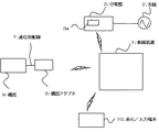
図1は、第1の実施形態に係る小規模ネットワークシステムを説明するための構成図である。1は、このネットワークシステムにおける集線装置(アクセスポイント)である。3は、電力系統2に接続された分電盤である。5は、機器9に通信用配線7を介して接続された機器アダプタである。10は、機器9の動作状態や消費電力を見える化する際の表示端末及び/または機器9の制御を行なうための入力端末である。
FIG. 1 is a configuration diagram for explaining a small-scale network system according to the first embodiment.
集線装置1と分電盤3、集線装置1と機器アダプタ5、集線装置1と表示/入力端末10とは相互に通信可能であり、通信手段は無線、有線のいずれでも構わない。図1では、これらのいずれについても無線接続による通信を例に示している。また、機器アダプタ5と機器9間の通信は、通信用配線7を用いずに、無線通信によることも可能である。
The
このような小規模ネットワークシステムとしては、家庭用ネットワークシステム、集合住宅用ネットワークシステム、ビル内ネットワークシステムの他、POSやCD等の業務用ネットワークシステム、監視制御用ネットワークシステム、ケーブルTV用ネットワークシステム、車両用ネットワークシステム等、種々のシステムがある。以下では、宅内ネットワークシステムを例に説明する。尚、宅内ネットワークシステムは、ネットワーク家電、ホームセキュリティ、オール電化、省エネ支援等の種々のニーズに応じたサービスを提供するための通信ネットワークシステムである。 Such small-scale network systems include home network systems, collective housing network systems, in-building network systems, business network systems such as POS and CD, monitoring and control network systems, cable TV network systems, There are various systems such as a vehicle network system. Hereinafter, a home network system will be described as an example. The home network system is a communication network system for providing services according to various needs such as network home appliances, home security, all electrification, and energy saving support.
集線装置1は、小規模ネットワークシステムを構築するための機器である。例えば、宅内ネットワークシステムによってエネルギーモニターサービスを提供する際に、集線装置1は、分電盤3内部の電力計測ユニット3aと接続して電力消費量データを受信し、受信したデータに基づいてユーザーに提供するモニター表示用データ等を生成する。集線装置1は、生成したモニター表示用データ等を表示/入力端末10に送信する。
The
あるいは、同様のエネルギーモニターサービスを提供する際に、集線装置1は、図1に示す宅内ネットワークシステムの外部にあるクラウドサーバー等(図示せず)の外部サーバとインターネット接続して、電力計測ユニット3aから受信したデータに必要なプロトコル変換等を施してインターネットサーバに送信し、外部サーバが生成したモニター表示用データ等を取得して、表示/入力端末10に送信する。外部サーバが生成したモニター表示用データは、インターネットを介してスマートフォン等の携帯表示端末や入力端末等に表示させることも可能であり、このようにすることで宅外からの当該サービスの利用が可能になる。
Alternatively, when providing the same energy monitoring service, the
また別の例では、宅内ネットワークシステムを用いてエネルギーモニター/制御サービスを提供する際に、集線装置1は、機器9の動作状態を、機器アダプタ5を介して収集し、表示端末10に送信するとともに、ユーザーが入力端末10に入力した要求に相応しい制御信号を、機器9の制御信号として機器アダプタ5に送出する。あるいは、集線装置1は、ユーザーが宅外で携帯端末等に入力した要求に応じた制御信号を外部サーバから取得し、機器9の制御信号として機器アダプタ5に送出する。機器アダプタ5は、受信した制御信号に応じて動作する。
In another example, when providing an energy monitoring / control service using a home network system, the
分電盤3は、系統2からの電力を宅内に安全に供給する機器であり、漏電ブレーカー、安全ブレーカー、電流ブレーカー等が備えられている。分電盤3は、さらに電力計測ユニット3aを備えており、電力計測ユニット3aは、分岐先に接続された電気機器9等の各機器の電力消費量を計測することが可能である。尚、図1では、複雑化を避けるために分電盤3と機器9間の電力配線を省略した。また、電力計測ユニット3aを分電盤3の筐体の外部に設置して、電力消費量を計測するための電圧値や電流値を分電盤3から無線あるいは有線の通信手段を介して受信する構成としてもよい。
The
機器アダプタ5は、集線装置1及び機器9と通信可能であり、集線装置1からの要求を受けて、必要な各種データを機器9に要求・受信し、受信したデータを集線装置1に向けて送信する等の機能を有する。各種データには、例えば、機器9の状態通知等がある。
The
機器9は、例えば、空調機等の白物家電、照明装置、床暖房、給湯器、ドアホン、蓄電池、電気自動車等のように主に電力を消費する電気機器の他、例えば太陽電池、蓄電池、電気自動車等のように創電する機器としてもよい。表示/入力端末10は、PCや専用モニター、あるいはスマートフォン等の携帯表示端末である。
The
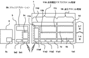
図2は、第1の実施形態に係るネットワークシステムの集線装置1、機器アダプタ5、機器9における通信プロトコルを説明するための構造図である。集線装置1は、装置本来の通信プロトコル階層1Aの他、機器アダプタの通信プロトコル階層11Aを備える。以下では、集線装置1にあるアダプタ用通信プロトコル階層11Aを、仮想機器アダプタプロトコル階層という。
FIG. 2 is a structural diagram for explaining a communication protocol in the
通信プロトコル階層1Aと仮想機器アダプタプロトコル階層11Aは、下位層から上位層まで、夫々、大きく1−4層と5−7層に分けることができる。階層の構成は、用いるプロトコルによって適宜変更することが可能であり、以下に示す階層構成は一例である。
The
プロトコル階層1Aは、仮想機器アダプタプロトコル階層11Aや、表示/入力装置10や、隣接するネットワーク機器と通信するための各種伝送媒体のドライバ1a1、・・・を備える。各種伝送媒体としては、例えば、BLUETOOTH(登録商標)、Wi−Fi(登録商標)、Ethernet(登録商標)、920MHz帯通信などがある。
The
また、伝送媒体のドライバ1a1、・・・の上の第2−4層1bには、PAN(Personal Area
Network)あるいは WPANと呼ばれる短距離無線ネットワーク通信層や、メディアアクセス制御層(MAC)、TCP/IP層等が含まれている。さらに、通信プロトコル階層1Aの第5−7層には、機器制御用プロトコル層1cの他、集線装置1のアプリケーション層1dが含まれている。
The second to fourth layers 1b above the transmission medium drivers 1a1,.
Network) or a short-range wireless network communication layer called WPAN, a media access control layer (MAC), a TCP / IP layer, and the like. Further, the 5th-7th layers of the
仮想機器アダプタプロトコル階層11Aの第1層は、集線装置1との通信に用いる伝送媒体用のドライバ11a1、11a2、11a3、・・・を備える。集線装置1との通信における伝送媒体は、例えば、BLUETOOTH、Wi−Fi、Ethernet、920MHz帯通信などがある。
The first layer of the virtual device adapter protocol layer 11A includes transmission medium drivers 11a1, 11a2, 11a3,... Used for communication with the
仮想機器アダプタプロトコル階層11Aの第1層は、さらに、機器アダプタ5との通信に用いる伝送媒体のドライバ11a4を備える。伝送媒体ドライバ11a4による通信には、各種の無線/有線通信を用いることができる。伝送媒体ドライバ11a4の上には、仮想通信ドライバ11eを設け、両者により仮想通信ポート(図中、破線枠で囲った部分)を構成することができる。
The first layer of the virtual device adapter protocol layer 11 </ b> A further includes a transmission medium driver 11 a 4 used for communication with the
尚、仮想通信ドライバ11eには、機器アダプタ5と機器9間の通信と同種の通信プロトコルを用いることで機器アダプタ5内のプロトコル変換が不要になり望ましい。例えば、機器アダプタ5と機器9間の通信にUARTによるシリアル通信を用いる場合には、集線装置1と機器アダプタ5間もUART(Universal Asynchronous Receiver Transmitter)によるシリアル通信を用いることが望ましい。UARTを用いる場合は、11eは仮想UARTドライバとする。
Note that it is desirable that the
シリアル通信プロトコルを伝送媒体にのせる際に、仮想通信ドライバ11eをシリアル通信用とし、仮想通信ドライバ11eと伝送媒体ドライバ11a4とで仮想通信ポートを構成することができる。この仮想通信ポートにより、仮想通信ドライバ5aと伝送媒体ドライバ5cとで構成される機器アダプタ5の仮想通信ポートと通信することができる。例えば、伝送媒体にBLUETOOTHを用いる場合は、仮想通信ポートにおいてUARTをBLUETOOTHで無線化することができる。尚、UART以外のシリアル通信を用いることも可能である。また、機器9−機器アダプタ5間の通信プロトコルと異なるプロトコルを用いても構わない。その場合は機器アダプタ5内に変換用のソフトとハードウェア資源が必要となる。
When the serial communication protocol is put on the transmission medium, the
仮想機器アダプタプロトコル階層11Aの第2―4層11bには、TCP/IP層が含まれる他、PANあるいは
WPANと呼ばれる短距離無線ネットワーク通信層や、メディアアクセス制御層(MAC)等を含めることができる。
The second to fourth layers 11b of the virtual device adapter protocol layer 11A include a TCP / IP layer, a short-range wireless network communication layer called PAN or WPAN, a media access control layer (MAC), and the like. it can.
仮想機器アダプタプロトコル階層11Aの第5−7層には、ECHONETやECHONET Lite(登録商標)等のアプリケーション層における機器制御用プロトコル層11cの他、機器オブジェクト等のアダプタアプリケーション層11d等が含まれている。ここで、機器オブジェクトは、オブジェクトに関する構造(インスタンス)や メソッド(操作、振舞い)等である。
Layers 5-7 of the virtual device adapter protocol layer 11A include a device
本実施の形態によれば、集線装置1内に仮想機器アダプタプロトコル階層11Aを設けることで、従来の機器アダプタに比べてハードウェア資源を軽装化することができる。具体的には、機器アダプタ5は、集線装置1との通信を可能にする特定の伝送媒体用ドライバ5a1と、仮想通信ドライバ5c、機器9との通信を可能にする伝送媒体用ドライバ5a2、これらを接続するためのブリッジアプリケーション5bを備えるのみである。これにより、従来、機器アダプタ5内にあったTCP/IP層等、あるいは、小規模インターネットにおけるアプリケーション層における機器制御用プロトコル層、機器オブジェクト等のアプリケーション層等を省略することできる。
According to the present embodiment, by providing the virtual device adapter protocol hierarchy 11A in the
従来の機器アダプタは、これらの層による処理を実行するためにRAMやROMに大容量のメモリーを必要とし、また、高速処理能力を備えるCPUを必要とする。本実施形態のようにTCP/IP層や機器制御用プロトコル層、機器オブジェクト等を機器アダプタ5から集線装置1に移すことで機器アダプタ5のハードウェアの大幅な軽装化を実現することができる。これにより、安価な機器アダプタ5を提供することが可能となる。尚、集線装置1は本来の集線機能を実現するためにもともと機器アダプタ5に比較して大きなメモリー容量と高速CPUを用いており、仮想機器アダプタプロトコル階層11Aの取り込みに伴い必要となるハードウェア資源の増加を吸収することは比較的容易である。
The conventional device adapter requires a large-capacity memory in the RAM and ROM in order to execute processing by these layers, and also requires a CPU having high-speed processing capability. The hardware of the
本実施の形態において、機器アダプタ5と機器9との間にBLUETOOTH SPP(Serial Port
Profile)による通信を用いることが望ましい。これにより、市販のBLUETOOTH SPPモジュールによる安価で簡略なシステムを提供することが可能となる。すなわち、市販のBLUETOOTH SPPモジュールは、BLUETOOTHドライバ5a1と仮想通信ドライバ5cにより構成される仮想通信ポート(図中、破線枠で囲った部分)、ブリッジアプリケーション5b、伝送媒体ドライバ5a2を標準実装しているため、簡便に機器アダプタ5を構築することができる。このような通信モジュールとしては、他に920MHz帯モジュールがある。従って、伝送媒体に920MHz帯通信を用いることも望ましい。
In the present embodiment, a BLUETOOTH SPP (Serial Port) is interposed between the
It is desirable to use communication by Profile). This makes it possible to provide an inexpensive and simple system using a commercially available BLUETOOTH SPP module. That is, the commercially available BLUETOOTH SPP module has a virtual communication port (a portion surrounded by a broken line in the figure) configured by the BLUETOOTH driver 5a1 and the
本実施の形態において、機器9が、外部との通信媒体として、例えばUART通信に対応している場合は、仮想機器アダプタプロトコル階層11Aの仮想通信ドライバ11eを仮想UARTドライバとすることができる。この場合には、機器アダプタ5には集線装置1のUARTプロトコルを理解する仮想UARTドライバ5cが内蔵させる。このような構成により、集線装置1と機器アダプタ5間の通信と、機器アダプタ5と機器9間の通信を同種の通信方式にして、機器アダプタ5内の変換処理等を回避することが可能となり、軽装化のために望ましい。
In the present embodiment, when the
この場合は、伝送媒体ドライバ11a4から送出された情報は、伝送媒体ドライバ5a1で受信された後、仮想UARTドライバ5cにより解釈され、ブリッジアプリケーション5bを経由して、UARTドライバ5a2から機器9のUARTドライバ9aに伝達される。UART9aに伝達された情報は、機器9の内部で解釈され、実行される。
In this case, after the information sent from the transmission medium driver 11a4 is received by the transmission medium driver 5a1, it is interpreted by the
ところで、集線装置1と機器アダプタ5との間の通信を無線により実現する場合は、有線に比べて通信が不安定である。従来は、機器アダプタに機器アダプタプロトコル階層が搭載されていたため、集線装置との接続が切断した場合に、機器アダプタから集線装置に対して、切断による運用不可の事象を通知することができなかった。
By the way, when the communication between the
これに対し、本実施の形態によれば、仮想機器アダプタプロトコル階層11Aを設けることで、機器アダプタ5との通信断による運用不可の通知を、集線装置1及び/又は他の仮想アダプタに通知することが可能となる。この通知を受け取った集線装置1は、例えば、表示/制御端末10に通知内容を送信することで、ユーザーに対して機器5がネットワークから外れた状態であることを知らしめることができる。
On the other hand, according to the present embodiment, by providing the virtual device adapter protocol layer 11A, a notification that the operation cannot be performed due to the communication disconnection with the
次に、本発明の第2の実施形態に係るネットワークシステムについて説明する。尚、第1の実施形態と同じ点は省略し、異なる点を中心に説明する。図3は、第2の実施形態に係るネットワークシステムを説明するための構成図である。第1の実施形態のネットワークシステムは、集線装置1に対して一つの機器アダプタ5を設けていた。第2の実施形態では、複数の機器アダプタ5、5’を含むネットワークシステムである。このようなネットワークシステムでは、複数の機器アダプタ5、5’に対応する仮想機器アダプタプロトコル階層11Aを集線装置1に設ける。
Next, a network system according to the second embodiment of the present invention will be described. Note that the same points as those in the first embodiment are omitted, and different points will be mainly described. FIG. 3 is a configuration diagram for explaining a network system according to the second embodiment. In the network system of the first embodiment, one
図3において、機器9、9’は、異種あるいは同種の電気機器であり、各電機機器9、9’には夫々、対応する機器アダプタ5、5’が設けられている。尚、機器の数は2以上の複数であればよく、ニーズに応じて増設可能である。また、図3では、電力計測ユニット3aの計測データを集線装置1と通信可能にする構成として、電力計測ユニット3aと別体の機器アダプタ5’’を設けている。
In FIG. 3, the
集線装置1に対して複数の機器アダプタ5を設ける場合、仮想機器アダプタプロトコル階層11Aを機器アダプタ5の数に応じて集線装置1内に増設することも可能である。例えば、ネットワーク内に機器アダプタ5を5つ設ける場合には、集線装置1内に通信プロトコル階層11Aを5つ設けることができる。
When a plurality of
しかし、集線装置1に機器アダプタ5の数と同数の通信プロトコル階層11Aを用いると、必要な資源は機器アダプタ5の数に単純比例して増加する。そこで、集線装置1内で可能な限り階層を共有化すれば、集線装置1の軽装化に寄与する。
However, if the same number of communication protocol layers 11A as the number of
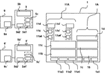
図4は、集線装置1の軽装化した階層構成を説明するためのソフトウェア構成図である。すなわち、仮想機器アダプタプロトコル階層11Aのうち、機器アダプタ間で共通化できる階層は共通化し、個々の機器アダプタ毎に対応する伝送媒体ドライバ11a4、仮想通信ドライバ11e、アダプタアプリケーション層11dからなる組を集線装置1内に機器アダプタ5と同数設ける。伝送媒体ドライバ11a4、仮想通信ドライバ11e、アダプタアプリケーション層11dは、機器アダプタ5との通信用であり、伝送媒体ドライバ11a4’、仮想シリアル通信ドライバ11e’、アダプタアプリケーション層11d’は、機器9’と繋がった機器アダプタ5’との通信用とすることができる。
FIG. 4 is a software configuration diagram for explaining a lighter hierarchical structure of the
このようにすることで、集線装置1の通信用伝送媒体ドライバ11a1、11a2、11a3や、11bに含まれるPANあるいは WPANと呼ばれる短距離無線ネットワーク通信層や、メディアアクセス制御層(MAC)、TCP/IP層等、さらに、アプリケーション層における機器制御用プロトコル層11c等を仮想アダプタ間で共通化することができる。これにより集線装置1の軽装化を図ることができる。
In this way, the communication transmission medium drivers 11a1, 11a2, 11a3 of the
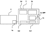
次に、本発明の第3の実施形態に係るネットワークシステムについて図5を用いて説明する。尚、第1の実施形態と同じ点は省略し、異なる点を中心に説明する。図5に示すように、機器アダプタ5に集線装置1と機器アダプタ5との無線区間の状態を機器9に通知するためのアプリケーション5cを搭載することができる。無線区間状態通知アプリケーション5cは、集線装置1と機器アダプタ5との通信断の事実を機器9に伝える通知を作成し、伝送媒体ドライバ5a2はこの通知を機器9の伝送媒体ドライバ9aに送信する。機器9側では、この通知を受けて、例えば、通信断以降に発生した事象に関するデータを自装置内に蓄積する、あるいは、通信断から一定期間経過時点で主電源を強制終了する、等の様々な対応が可能となる。
Next, a network system according to the third embodiment of the present invention will be described with reference to FIG. Note that the same points as those in the first embodiment are omitted, and different points will be mainly described. As shown in FIG. 5, an
次に、本発明の第4の実施形態について図6を用いて説明する。尚、第1の実施形態と同じ点は省略し、異なる点を中心に説明する。一般に、機器アダプタ5や機器9の立上げ時には、両者間で同期を取る等の初期化工程が必要である。第1乃至第3の実施形態のいずれかのネットワークシステムにおいてこのような初期化工程を行なう例を第4の実施形態として説明する。
Next, a fourth embodiment of the present invention will be described with reference to FIG. Note that the same points as those in the first embodiment are omitted, and different points will be mainly described. Generally, when starting up the
機器アダプタ5と機器9を繋ぐ通信用配線7は、制御信号を伝達する制御線を含んでいる。通信用配線7による初期化には、この制御線を用いることができる。
The communication wiring 7 that connects the
図6は、制御線を用いた初期化信号とUART等によるシリアル信号をカプセル化する手法を説明する図である。UART等によるシリアル信号と初期化信号は、夫々、機器9から機器アダプタ5に送出され、機器アダプタ5のブリッジアプリケーション5bでカプセル化された後、集線装置1に送信される。
FIG. 6 is a diagram for explaining a method of encapsulating an initialization signal using a control line and a serial signal by UART or the like. A serial signal and an initialization signal by UART or the like are transmitted from the
図6に示す例では、機器9から機器アダプタ5へ送られてくるUART等のシリアルデータを、仮に8ビット(b0,
b1, b2, b3, b4, b5, b6, b7)からなるキャラクタとする。また、制御線により伝達する制御信号を、仮にリセット情報(r)と、機器状態を示す情報(p)との2ビットのデータ列とする。リセット情報は、新たに接続を確立した旨を示す情報であり、後続ビットが機器状態を示す情報(p)であることを示す。機器状態を示す情報(p)は、機器9の状態を示す情報であり、例えば、電源がON/OFF状態を示す情報である。
In the example shown in FIG. 6, the serial data such as UART sent from the
b1, b2, b3, b4, b5, b6, b7). Further, a control signal transmitted through the control line is assumed to be a 2-bit data string of reset information (r) and information (p) indicating the device state. The reset information is information indicating that a new connection has been established, and indicates that the subsequent bit is information (p) indicating the device status. The information (p) indicating the device state is information indicating the state of the
カプセル化の例1について説明する。カプセル化の例1では、機器アダプタ5が受けるシリアルデータ(b0, b1,
b2, b3, b4, b5, b6, b7)に制御信号(r, p)を加えた計10ビットを一つのキャラクタとしてカプセル化している。カプセル化されたキャラクタは機器アダプタ5から集線装置1に送出される。
An example 1 of encapsulation will be described. In the encapsulation example 1, the serial data (b0, b1,
b2, b3, b4, b5, b6, b7) and control signals (r, p) plus 10 bits are encapsulated as one character. The encapsulated character is sent from the
図6に示すカプセル化の例2について説明する。カプセル化の例2では、機器アダプタ5が受けるシリアルデータ(b0,
b1, b2, b3, b4, b5, b6, b7)と制御信号(r, p)を加えた計10ビットを、キャラクタ長が8ビットの2つのキャラクタに分割してカプセル化している。最初のキャラクタの冒頭のビットには、一連のシリアル通信における最初のキャラクタを示す識別子(固定値)が入る。図6ではこの識別子を、例として(0)とした。この識別子の後ろにはシリアルデータ(b0, b1, b2, b3, b4,
b5, b6)が続く。次のキャラクタの冒頭のビットには、一連のシリアル通信における2番目のキャラクタを示す識別子(固定値)が入る。図6では、例として(1)とした。この識別子の後には最初のキャラクタに含まれないデータ(b7)が入り、続いて、制御信号(r, p)が入る。制御信号(r,p)の後はパディングフィールドで、キャラクタ長に満たないビット数(この例ではキャラクタ長である8ビットから既に充填した4ビットを差し引いた残りの4ビット)だけ(0)がパディングされている。
An encapsulation example 2 shown in FIG. 6 will be described. In the encapsulation example 2, the serial data (b0,
b1, b2, b3, b4, b5, b6, b7) and control signals (r, p) in total are divided into two characters having a character length of 8 bits and encapsulated. The first bit of the first character contains an identifier (fixed value) indicating the first character in a series of serial communications. In FIG. 6, this identifier is (0) as an example. This identifier is followed by serial data (b0, b1, b2, b3, b4,
b5, b6) follow. The first bit of the next character contains an identifier (fixed value) indicating the second character in a series of serial communications. In FIG. 6, (1) is taken as an example. This identifier is followed by data (b7) not included in the first character, followed by a control signal (r, p). After the control signal (r, p), in the padding field, only (0) is the number of bits less than the character length (in this example, the remaining 4 bits obtained by subtracting 4 bits already filled from the 8 bits which are the character length). It is padded.
以上、本発明の実施形態を説明したが、これら実施形態は、例として提示したものであり、発明の範囲を限定することは意図していない。これら実施形態は、その他の様々な形態で実施されることが可能であり、発明の要旨を逸脱しない範囲で、種々の省略、置き換え、変更を行うことができる。これらの実施形態は、発明の範囲や要旨に含まれると同様に、特許請求の範囲に記載された発明とその均等の範囲に含まれるものである。 As mentioned above, although embodiment of this invention was described, these embodiment is shown as an example and is not intending limiting the range of invention. These embodiments can be implemented in various other forms, and various omissions, replacements, and changes can be made without departing from the spirit of the invention. These embodiments are included in the scope and gist of the invention, and are also included in the invention described in the scope of claims and the equivalents thereof.
1…集線装置、2…系統、3…分電盤、5…機器アダプタ、7…通信用配線、9…機器、10…表示/入力端末、11A…仮想機器アダプタプロトコル階層
DESCRIPTION OF
Claims (6)
前記第一の仮想通信ポートとの間で通信可能な第二の仮想通信ポート、TCP/IP層、アプリケーション層における機器制御用プロトコル層、及び機器オブジェクトを備える仮想機器アダプタプロトコル階層を備える集線装置と、を具備することを特徴とするネットワークシステム。 A device adapter comprising a first virtual communication port;
A concentrator having a second virtual communication port communicable with the first virtual communication port, a TCP / IP layer, a device control protocol layer in the application layer, and a virtual device adapter protocol layer comprising device objects; A network system comprising:
Priority Applications (4)
| Application Number | Priority Date | Filing Date | Title |
|---|---|---|---|
| JP2012280540A JP2014127724A (en) | 2012-12-25 | 2012-12-25 | Network system and concentrator |
| EP13180516.0A EP2750334A1 (en) | 2012-12-25 | 2013-08-15 | Network system and network connection device |
| US14/014,535 US20140181315A1 (en) | 2012-12-25 | 2013-08-30 | Network System and Network Connection Device |
| CN201310391118.7A CN103905210A (en) | 2012-12-25 | 2013-08-30 | Network system and network connection device |
Applications Claiming Priority (1)
| Application Number | Priority Date | Filing Date | Title |
|---|---|---|---|
| JP2012280540A JP2014127724A (en) | 2012-12-25 | 2012-12-25 | Network system and concentrator |
Publications (1)
| Publication Number | Publication Date |
|---|---|
| JP2014127724A true JP2014127724A (en) | 2014-07-07 |
Family
ID=49000815
Family Applications (1)
| Application Number | Title | Priority Date | Filing Date |
|---|---|---|---|
| JP2012280540A Pending JP2014127724A (en) | 2012-12-25 | 2012-12-25 | Network system and concentrator |
Country Status (4)
| Country | Link |
|---|---|
| US (1) | US20140181315A1 (en) |
| EP (1) | EP2750334A1 (en) |
| JP (1) | JP2014127724A (en) |
| CN (1) | CN103905210A (en) |
Cited By (1)
| Publication number | Priority date | Publication date | Assignee | Title |
|---|---|---|---|---|
| JP2017054428A (en) * | 2015-09-11 | 2017-03-16 | 株式会社東芝 | Communication adapter, communication method and program |
Families Citing this family (2)
| Publication number | Priority date | Publication date | Assignee | Title |
|---|---|---|---|---|
| CN104869157A (en) * | 2015-04-29 | 2015-08-26 | 杭州电子科技大学 | Universal automated information collecting and monitoring system for industry |
| US11616781B2 (en) * | 2017-12-05 | 2023-03-28 | Goldilock Secure s.r.o. | Air gap-based network isolation device |
Family Cites Families (6)
| Publication number | Priority date | Publication date | Assignee | Title |
|---|---|---|---|---|
| US6718419B1 (en) * | 1999-11-17 | 2004-04-06 | Globespanvirata, Inc. | System and method for extending the number of addressable physical devices on a data bus |
| KR100638030B1 (en) * | 2003-05-30 | 2006-10-23 | 엘지전자 주식회사 | Network electric device |
| US20060181982A1 (en) * | 2005-02-11 | 2006-08-17 | Villevieille Jean-Marc A | Wireless adaptor for content transfer |
| JP2008152343A (en) * | 2006-12-14 | 2008-07-03 | Toshiba Corp | Home electric appliance controller and home electric appliance control method |
| KR101303718B1 (en) * | 2009-02-27 | 2013-09-04 | 브로드콤 코포레이션 | Method and system for virtual machine networking |
| KR101405977B1 (en) * | 2010-02-23 | 2014-06-13 | 엘지전자 주식회사 | A method and an apparatus for transmitting messages in home network system |
-
2012
- 2012-12-25 JP JP2012280540A patent/JP2014127724A/en active Pending
-
2013
- 2013-08-15 EP EP13180516.0A patent/EP2750334A1/en not_active Withdrawn
- 2013-08-30 US US14/014,535 patent/US20140181315A1/en not_active Abandoned
- 2013-08-30 CN CN201310391118.7A patent/CN103905210A/en active Pending
Cited By (1)
| Publication number | Priority date | Publication date | Assignee | Title |
|---|---|---|---|---|
| JP2017054428A (en) * | 2015-09-11 | 2017-03-16 | 株式会社東芝 | Communication adapter, communication method and program |
Also Published As
| Publication number | Publication date |
|---|---|
| US20140181315A1 (en) | 2014-06-26 |
| EP2750334A1 (en) | 2014-07-02 |
| CN103905210A (en) | 2014-07-02 |
Similar Documents
| Publication | Publication Date | Title |
|---|---|---|
| US10237807B2 (en) | System and method for mixed-mesh wireless networking | |
| EP2748999B1 (en) | Ethernet physical layer monitoring system employing social networking service for delivery of alerts to mobile devices | |
| JP2013520944A5 (en) | ||
| Chen et al. | Implementing the design of smart home and achieving energy conservation | |
| CN108572934A (en) | The discovery mechanism of universal serial bus (USB) protocol adaptation layers | |
| JP2014127724A (en) | Network system and concentrator | |
| CN202111864U (en) | Distributed wireless gateway system | |
| JP5339654B1 (en) | Wireless relay system for IEEE802.11 standard communication and IEEE802.15.4 standard communication | |
| CN202261834U (en) | Multifunctional wireless router | |
| CN106604359A (en) | Networking method of mobile phone and plurality of vehicle-mounted WiFi, and WiFi equipment used for same | |
| Sreeram et al. | A novel architecture for IoT and smart community | |
| Bai et al. | Design and implementation of an IoT multi-interface gateway for establishing a digital art interactive system | |
| EP2905999B1 (en) | Data transmission method, multi-medium access point and multi-medium client | |
| JP6762105B2 (en) | Communication equipment and emergency signal transmission system | |
| JP6721958B2 (en) | Centralized monitoring system | |
| CN104375969A (en) | Base device and connecting method thereof | |
| JP2014078939A (en) | Apparatus and method for wireless mesh network communications | |
| KR20160100434A (en) | Apparatus for can convert and can to bluetooth system using thereof | |
| JP3197162U (en) | Network control integrated box | |
| JP2016115201A (en) | Equipment management device, equipment management system, and program | |
| CN115002175A (en) | Remote control method, device and storage medium | |
| US9369828B2 (en) | Radio network with a low power consumption and method for operating such a radio network | |
| JP5974630B2 (en) | Information management apparatus, information management method, and information management program | |
| EP3048833A1 (en) | Communication allowability range output system, communication allowability range output device, method, and program | |
| JP2012160931A (en) | Radio communication repeater and program therefor |