EP2750334A1 - Network system and network connection device - Google Patents
Network system and network connection device Download PDFInfo
- Publication number
- EP2750334A1 EP2750334A1 EP13180516.0A EP13180516A EP2750334A1 EP 2750334 A1 EP2750334 A1 EP 2750334A1 EP 13180516 A EP13180516 A EP 13180516A EP 2750334 A1 EP2750334 A1 EP 2750334A1
- Authority
- EP
- European Patent Office
- Prior art keywords
- virtual
- communication
- device adapter
- adapter
- network system
- Prior art date
- Legal status (The legal status is an assumption and is not a legal conclusion. Google has not performed a legal analysis and makes no representation as to the accuracy of the status listed.)
- Withdrawn
Links
Images


Classifications
-
- H—ELECTRICITY
- H04—ELECTRIC COMMUNICATION TECHNIQUE
- H04L—TRANSMISSION OF DIGITAL INFORMATION, e.g. TELEGRAPHIC COMMUNICATION
- H04L41/00—Arrangements for maintenance, administration or management of data switching networks, e.g. of packet switching networks
- H04L41/02—Standardisation; Integration
-
- H—ELECTRICITY
- H04—ELECTRIC COMMUNICATION TECHNIQUE
- H04L—TRANSMISSION OF DIGITAL INFORMATION, e.g. TELEGRAPHIC COMMUNICATION
- H04L12/00—Data switching networks
- H04L12/28—Data switching networks characterised by path configuration, e.g. LAN [Local Area Networks] or WAN [Wide Area Networks]
- H04L12/2803—Home automation networks
Definitions
- Embodiments described herein relate generally to a small-scale network system and a network connection device used for the same.
- a middleware adapter (device adapter) in a small-scale network such as ECHONET (registered trademark) includes a device interface driver (I/F driver), a device object processing part, a packet processing part of ECHONET, a UDP/IP processing part and a transmission media (medium) processing part.
- the middleware adapter itself includes the device interface driver (I/F driver), the device object processing part, the packet processing part of ECHONET and the UDP/IP processing part.
- I/F driver the device interface driver
- the device object processing part the packet processing part of ECHONET
- UDP/IP processing part the UDP/IP processing part.
- memories such as RAM/ROM are required.
- a high-performance CPU is required.
- the device adapter of the related art requires the large-capacity and high-performance hardware resources.
- a network and a network connection device are provided in which hardware resources can be reduced without lowering the communication performance of the network.
- a network system includes a device adapter including a first virtual communication port, and a network connection device including a virtual device adapter protocol hierachy.
- the virtual device adapter protocol hierarchy includes i) a second virtual communication port communicable with the first virtual communication port, ii) a TCP/IP layer, iii) a device controlling protocol layer in an application layer and iv) a device object.
- a network connection device includes a virtual device adapter protocol hierarchy.
- the virtual device adapter protocol hierarchy includes i) a second virtual communication port communicable with a first virtual communication port of a device adapter, ii) a TCP/IP layer, iii) a device controlling protocol layer in an application layer and iv) a device object.
- FIG. 1 is a structural view for explaining a small-scale network system according to a first embodiment.
- Reference numeral 1 denotes a hub or an access point (network connection device) in this network system and is represented as hub/ access point.
- a panel board 3 is connected to an electric power system 2.
- a device adapter 5 is connected to a device 9 through a communication wiring 7.
- a display and/or input terminal 10 is used for displaying an operation state and power consumption of the device 9 and/or is used for controlling the device 9.
- the hub/access point 1 and the panel board 3, the hub/ access point 1 and the device adapter 5, and the hub/ access point 1 and the display/input terminal 10 can communicate with each other.
- a communication unit may be wireless or wired.
- FIG. 1 shows an example in which communication by wireless connection is performed for any of these. Besides, the communication between the device adapter 5 and the device 9 can also be performed by wireless communication without using the communication wiring 7.
- the small-scale network system there are various systems such as a home network system, a collective housing network system, an in-building network system, a business network system such as POS or CD, a monitor control network system, a cable TV network system, and a vehicle network system.
- a description will be made while using an in-house network system as an example.
- the in-house network system is a communication network system for providing services according to various needs, such as network home electric appliances, home security, all electrification, and power-saving support.
- the hub/ access point 1 is a device for configuring the small-scale network system. For example, when energy monitor service is provided by the in-house network system, the hub/ access point 1 is connected to a power measuring unit 3a in the panel board 3, receives power consumption amount data, and generates monitor display data to be provided to the user based on the received data. The hub/ access point 1 transmits the generated monitor display data to the display/input terminal 10.
- the hub/ access point 1 is connected via Internet to an external server such as a cloud server (not shown) existing outside the in-house network system shown in FIG. 1 , and performs required protocol conversion to the data received from the power measuring unit 3a. Then, the hub/ access point transmits the data to the Internet server, acquires monitor display data generated by the external server, and transmits the data to the display/input terminal 10.
- the monitor display data generated by the external server can also be displayed on a mobile display terminal or an input terminal, such as a smartphone, via Internet. By doing so, the service can be used from the outside of the house.
- the hub/ access point 1 collects the operation state of the device 9 through the device adapter 5, and transmits it to the display terminal 10. Further, the hub/ access point 1 transmits a control signal, which corresponds to request inputted to the input terminal 10 by the user and is a control signal of the device 9, to the device adapter 5. Alternatively, the hub/ access point 1 acquires a control signal, which corresponds to request inputted to the mobile terminal by the user at the outside of the house, from the external server, and transmits the signal as the control signal of the device 9 to the device adapter 5. The device adapter 5 operates according to the received control signal.
- the panel board 3 is the device for safely supplying the power from the system 2 to the house, and includes an earth leakage breaker, a safety breaker, a current breaker and the like.
- the panel board 3 further includes the power measuring unit 3a, and the power measuring unit 3a can measure the power consumption amount of each device, such as the electric device 9, connected to a branching destination.
- the power wiring between the panel board 3 and the device 9 is omitted in order to avoid complication.
- the power measuring unit 3a is placed outside the housing of the panel board 3, and a voltage value or current value for measuring the power consumption amount may be received from the panel board 3 through a wireless or wired communication unit.
- the device adapter 5 can communicate with the hub/ access point 1 and the device 9, and has a function to receive a request from the hub/ access point 1, to request and receive various required data to and from the device 9, and to transmit the received data to the hub/ access point 1.
- the various data include, for example, state notification of the device 9.
- the device 9 may be an electric device mainly consuming power, for example, white goods such as an air conditioner, a luminaire, floor heating, a water heater, a door phone, a battery or an electric car, or may be a device to generate power such as a solar cell, a battery or an electric car.
- the display/input terminal 10 is a PC, a dedicated monitor or a mobile display terminal such as a smartphone.
- FIG. 2 is a structural view for explaining a communication protocol in the hub/ access point 1, the device adapter 5 and the device 9 of the network system of the first embodiment.
- the hub/ access point 1 includes a communication protocol hierarchy 11A of the device adapter in addition to a communication protocol hierarchy 1A intrinsic to the hub/ access point.
- the adapter communication protocol hierarchy 11A in the hub/access point 1 is called a virtual device adapter protocol hierarchy.
- the communication protocol hierarchy 1A and the virtual device adapter protocol hierarchy 11A can be respectively roughly divided into first to fourth layers and fifth to seventh layers from a lower layer to a higher layer.
- the structure of the hierarchy can be suitably changed according to the protocol to be used, and the hierarchy structure described below is an example.
- the protocol hierarchy 1A includes drivers 1a1, ⁇ ⁇ ⁇ of various transmission media for communicating with the adjacent network device, and includes virtual device adapter protocol hierarchy 11A and the display/input device 10.
- various transmission media there are, for example, BLUETOOTH (registered trademark), Wi-Fi (registered trademark), Ethernet (registered trademark) and 920 MHz band communication.
- the second to fourth layers 1b on the drivers 1a1, ⁇ ⁇ ⁇ of the transmission media includes a short distance wireless network communication layer called PAN (Personal Area Network) or WPAN, a media access control layer (MAC), a TCP/IP (Transmission Control Protocol / Internet Protocol) layer and the like.
- the fifth to seventh layers of the communication protocol hierarchy 1A includes an application layer 1d of the hub/ access point 1 in addition to a device controlling protocol layer 1c.
- the first layer of the virtual device adapter protocol hierarchy 11A further includes a driver 11a4 of a transmission medium used for communication with the device adapter 5.
- Various wireless/wired communication can be used for communication by the transmission medium driver 11a4.
- a virtual communication driver 11e is provided on the transmission medium driver 11a4, and both can constitute a virtual communication port (in the drawing, a portion surrounded by a broken line frame).
- the virtual communication driver 11e if a communication protocol similar to the communication between the device adapter 5 and the device 9 is used in the virtual communication driver 11e, protocol conversion in the device adapter 5 becomes unnecessary, and this is desirable.
- the serial communication by UART Universal Asynchronous Receiver Transmitter
- the driver 11e is the virtual UART driver.
- the virtual communication driver 11e When the serial communication protocol is placed on the transmission medium, the virtual communication driver 11e is used for the serial communication, and the virtual communication driver 11e and the transmission medium driver 11a4 can constitute the virtual communication port.
- This virtual communication port enables communication with a virtual communication port of the device adapter 5 constituted by a transmission medium driver 5a1 and a virtual communication driver 5c.
- BLUETOOTH when BLUETOOTH is used as the transmission medium, UART can be made wireless by BLUETOOTH in the virtual communication port. Besides serial communication other than UART can also be used.
- a protocol different from the communication protocol between the device 9 and the device adapter 5 may be used. In that case, software and hardware resources for conversion are required in the device adapter 5.
- the second to fourth layers 11b of the virtual device adapter protocol hierarchy 11A include a TCP/IP layer, and can include a short distance wireless network communication layer called PAN or WPAN, a media access control layer (MAC), and the like.
- PAN short distance wireless network communication layer
- WPAN wireless personal area network
- MAC media access control layer
- the fifth to seventh layers of the virtual device adapter protocol hierarchy 11A include an adapter application layer 11d such as a device object, in addition to a device controlling protocol layer 11c in an application layer of ECHONET or ECHONET Lite (registered trademark).
- the device object is a structure (instance) relating to an object, a method (operation, behavior) or the like.
- the virtual device adapter protocol hierarchy 11A is provided in the hub/ access point 1.
- the device adapter 5 merely includes a specific transmission medium driver 5a1 to enable communication with the hub/ access point 1, the virtual communication driver 5c, a transmission medium driver 5a2 to enable communication with the device 9, and a bridge application 5b for connecting these.
- This can omit the TCP/IP layer and the like, which existed in the device adapter 5 in the related art, or can omit a device controlling protocol layer in an application layer in small-scale Internet, an application layer of a device object, and the like.
- the device adapter of the related art requires a large-capacity memory for RAM or ROM in order to perform the processes of these layers, and requires a CPU having high-speed processing performance.
- the hardware of the device adapter 5 can be greatly reduced.
- the inexpensive device adapter 5 can be provided.
- the hub/ access point 1 originally uses a large memory capacity and a high speed CPU as compared with the device adapter 5 in order to realize the original hub/ access point function.
- the increase of hardware resources required by the addition of the virtual device adapter protocol hierarchy 11A can be relatively easily absorbed.
- communication by BLUETOOTH SPP Serial Port Profile
- BLUETOOTH SPP Serial Port Profile
- the inexpensive and simple system using a commercially available BLUETOOTH SPP module can be provided. That is, since the commercially available BLUETOOTH SPP module is normally provided with the virtual communication port (in the drawing, the portion surrounded by the broken line) constituted by the BLUETOOTH driver 5a1 and the virtual communication driver 5c, the bridge application 5b, and the transmission medium driver 5a2, the device adapter 5 can be easily configured.
- the communication module as stated above, there is also a 920 MHz band module. Accordingly, the 920 MHz band communication is also desirably used as the transmission media.
- the virtual communication driver 11e of the virtual device adapter protocol hierarchy 11A can be made the virtual UART driver.
- the device adapter 5 includes the virtual UART driver 5c which understand the UART protocol of the hub/ access point 1.
- information transmitted from the transmission medium driver 11a4 is received by the transmission medium driver 5a1. And then, the information is interpreted by the virtual UART driver 5c, and is transmitted from the UART driver 5a2 to the UART driver 9a of the device 9 via the bridge application 5b. The information transmitted to the UART 9a is interpreted in the inside of the device 9, and is executed.
- the communication between the hub/ access point 1 and the device adapter 5 is realized by wireless, as compared with wired communication, the communication is unstable. Hitherto, since the device adapter protocol hierarchy is installed on the device adapter, when the connection with the hub/ access point is disconnected, an event that an operation is impossible due to the disconnection can not be notified to the hub/ access point from the device adapter.
- the virtual device adapter protocol hierarchy 11A since the virtual device adapter protocol hierarchy 11A is provided, notification that an operation is impossible due to the disconnection of communication with the device adapter 5 can be notified to the hub/ access point 1 and/or other virtual adapters.
- the hub/ access point 1 receiving this notification transmits the notification content to, for example, the display/control terminal 10, and can notify the user that the device 5 is in the state of being disconnected from the network.
- FIG. 3 is a structural view for explaining the network system of the second embodiment.
- the one device adapter 5 is provided for the hub/ access point 1.
- the network system includes plural device adopters 5 and 5'.
- a virtual device adapter protocol hierarchy 11A corresponding to the plural device adapters 5 and 5' is provided in a hub/ access point 1.
- devices 9 and 9' are the same kind or different kind of electric devices, and the respective electric devices 9 and 9' are provided with the corresponding device adapters 5 and 5'.
- the number of the devices may be two or more, and the number can be increased according to needs.
- a device adapter 5" separate from a power measurement unit 3a is provided, so that measurement data of the power measurement unit 3a is communicable with the hub/ access point 1.
- the virtual device adapter protocol hierarchy 11A can be increased in the hub/ access point 1 according to the number of the device adopters 5. For example, when five device adopters 5 are provided in the network, five communication protocol hierarchies 11A can be provided in the hub/ access point 1.
- the communication protocol hierarchies 11A the number of which is equal to the number of the device adopters 5 are used in the hub/ access point 1, the required resources increase simply in proportion to the number of the device adopters 5. Then, if the hierarchies are made common as much as possible in the hub/ access point 1, the hub/ access point 1 can be reduced (simplified).
- FIG. 4 is a software structural view for explaining the reduced hierarchy structure of the hub/ access point 1. That is, in the virtual device adapter protocol hierarchy 11A, hierarchies which can be made common among the device adapters are made common. A set of a transmission medium driver 11a4, a virtual communication driver 11e and an adapter application layer 11d is formed corresponding to each device adapter and a plurality of such sets are provided in the hub/ access point 1. The number of the sets is equal to the number of the device adopters 5. The transmission medium driver 11a4, the virtual communication driver 11e, and the adapter application layer 11d are for communication with the device adapter 5. A transmission medium driver 11a4', a virtual serial communication driver 11e', and an adapter application layer 11d' are for communication with the device adapter 5' connected with the device 9'.
- the communication transmission medium drivers 11a1, 11a2 and 11a3 of the hub/ access point 1 and also the short distance wireless network communication layer called PAN or WPAN, the media access control layer (MAC) and the TCP/IP layer, included in 11b, and further, the device controlling protocol layer 11c in the application layer, and the like can be made common among the virtual device adapters.
- the hub/ access point 1 can be reduced.
- an application 5d for notifying a state of a wireless section between a hub/ access point 1 and a device adapter 5 to a device 9 can be installed on the device adapter 5.
- the wireless section state notification application 5d creates a notification to notify the device 9 of a fact that communication between the hub/ access point 1 and the device adapter 5 is disconnected, and a transmission medium driver 5a2 transmits this notification to a transmission medium driver 9a of the device 9.
- the device 9 receives this notification, and can take various measures.
- the device 9 itself stores data relating to an event occurring after the communication disconnection, or forcibly terminates main power supply at a time point when a specific period passes from the communication disconnection.
- a fourth embodiment of the invention will be described with reference to FIG. 6 .
- the same points as those of the first embodiment are omitted, and different points will be mainly described.
- an initialization process such as establishment of synchronization between both, is required.
- An example in which the initialization process is performed in the network system of any one of the first to third embodiments will be described as the fourth embodiment.
- the communication wiring 7 for connecting the device adapter 5 and the device 9 includes a control line for transmitting a control signal. This control line can be used for the initialization by the communication wiring 7.
- FIG. 6 is a view for explaining a method of capsulizing an initialization signal using the control line and a serial signal by UART or the like.
- the serial signal by UART or the like and the initialization signal are respectively transmitted from the device 9 to the device adapter 5, and are capsulized by the bridge application 5b of the device adapter 5. Thereafter, the signals are transmitted to the hub/ access point 1.
- serial data of UART or the like transmitted from the device 9 to the device adapter 5 is assumed to be a character of 8 bits (b0, b1, b2, b3, b4, b5, b6, b7).
- the control signal transmitted through the control line is assumed to be a 2-bit data string of reset information (r) and information (p) indicating a device state.
- the reset information is information indicating that connection is newly established, and indicates that the subsequent bit is the information (p) indicating the device state.
- the information (p) indicating the device state is information indicating the state of the device 9, and is, for example, information indicating the ON/OFF state of the power supply.
- Example 1 of capsulization will be described.
- total 10 bits including the serial data (b0, b1, b2, b3, b4, b5, b6, b7) received by the device adapter 5 and the control signal (r, p) are capsulized as one character.
- the capsulized character is transmitted from the device adapter 5 to the hub/ access point 1.
- Example 2 of capsulization shown in FIG. 6 will be described.
- total 10 bits including the serial data (b0, b1, b2, b3, b4, b5, b6, b7) received by the device adapter 5 and the control signal (r, p) are divided into two characters each having a character length of 8 bits and are capsulized.
- An identifier (fixed value) indicating the first character in a series of serial communications is placed in the first bit of the first character. In FIG. 6 , this identifier is, for example, (0).
- the serial data (b0, b1, b2, b3, b4, b5, b6) follows this identifier.
- An identifier (fixed value) indicating the second character in the series of serial communications is placed in the first bit of the next character.
- the identifier is, for example, (1).
- the data (b7) not contained in the first character is placed after this identifier, and subsequently, the control signal (r, p) is placed.
- a padding field follows the control signal (r, p), and (0) is padded in bits required to obtain the character length (in this example, 4 bits obtained by subtracting the already filled 4 bits from 8 bits of the character length).
Abstract
Description
- This application is based upon and claims the benefit of priority from the prior Japanese Patent Application No.
2012-280540, filed on December 25, 2012 - Embodiments described herein relate generally to a small-scale network system and a network connection device used for the same.
- Formerly, a middleware adapter (device adapter) in a small-scale network such as ECHONET (registered trademark) includes a device interface driver (I/F driver), a device object processing part, a packet processing part of ECHONET, a UDP/IP processing part and a transmission media (medium) processing part.
- For example, hitherto, the middleware adapter (device adapter, etc.) itself includes the device interface driver (I/F driver), the device object processing part, the packet processing part of ECHONET and the UDP/IP processing part. In order to mount these processing parts, memories such as RAM/ROM are required. Besides, in order to perform a data conversion process at high speed, a high-performance CPU is required. As described above, the device adapter of the related art requires the large-capacity and high-performance hardware resources.
-
-
FIG. 1 is a structural view for explaining a network system according to a first embodiment. -
FIG. 2 is a structural view for explaining a network connection device, a device adapter and a device communication protocol according to the first embodiment. -
FIG. 3 is a structural view for explaining a network system according to a second embodiment. -
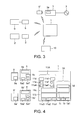
FIG. 4 is a structural view for explaining a communication protocol in a network connection device according to the second embodiment. -
FIG. 5 is a structural view for explaining a device adapter and a device communication protocol according to a third embodiment. -
FIG. 6 is a view for explaining capsulization according to a fourth embodiment. - In view of the above circumstances, according to one embodiment, a network and a network connection device are provided in which hardware resources can be reduced without lowering the communication performance of the network.
- According to one embodiment, a network system includes a device adapter including a first virtual communication port, and a network connection device including a virtual device adapter protocol hierachy. The virtual device adapter protocol hierarchy includes i) a second virtual communication port communicable with the first virtual communication port, ii) a TCP/IP layer, iii) a device controlling protocol layer in an application layer and iv) a device object.
- Besides, according to another embodiment, a network connection device includes a virtual device adapter protocol hierarchy. The virtual device adapter protocol hierarchy includes i) a second virtual communication port communicable with a first virtual communication port of a device adapter, ii) a TCP/IP layer, iii) a device controlling protocol layer in an application layer and iv) a device object.
- According to the network system and the network connection device of the above respective embodiments, hardware resources can be reduced.
- Hereinafter, embodiments will be described with reference to the drawings.
-
FIG. 1 is a structural view for explaining a small-scale network system according to a first embodiment.Reference numeral 1 denotes a hub or an access point (network connection device) in this network system and is represented as hub/ access point. Apanel board 3 is connected to anelectric power system 2. Adevice adapter 5 is connected to adevice 9 through acommunication wiring 7. A display and/orinput terminal 10 is used for displaying an operation state and power consumption of thedevice 9 and/or is used for controlling thedevice 9. - The hub/
access point 1 and thepanel board 3, the hub/access point 1 and thedevice adapter 5, and the hub/access point 1 and the display/input terminal 10 can communicate with each other. A communication unit may be wireless or wired.FIG. 1 shows an example in which communication by wireless connection is performed for any of these. Besides, the communication between thedevice adapter 5 and thedevice 9 can also be performed by wireless communication without using thecommunication wiring 7. - As the small-scale network system, there are various systems such as a home network system, a collective housing network system, an in-building network system, a business network system such as POS or CD, a monitor control network system, a cable TV network system, and a vehicle network system. Hereinafter, a description will be made while using an in-house network system as an example. Incidentally, the in-house network system is a communication network system for providing services according to various needs, such as network home electric appliances, home security, all electrification, and power-saving support.
- The hub/
access point 1 is a device for configuring the small-scale network system. For example, when energy monitor service is provided by the in-house network system, the hub/access point 1 is connected to apower measuring unit 3a in thepanel board 3, receives power consumption amount data, and generates monitor display data to be provided to the user based on the received data. The hub/access point 1 transmits the generated monitor display data to the display/input terminal 10. - Alternatively, when similar energy monitor service is provided, the hub/
access point 1 is connected via Internet to an external server such as a cloud server (not shown) existing outside the in-house network system shown inFIG. 1 , and performs required protocol conversion to the data received from thepower measuring unit 3a. Then, the hub/ access point transmits the data to the Internet server, acquires monitor display data generated by the external server, and transmits the data to the display/input terminal 10. The monitor display data generated by the external server can also be displayed on a mobile display terminal or an input terminal, such as a smartphone, via Internet. By doing so, the service can be used from the outside of the house. - In another example, when the energy monitor/control service is provided using the in-house network system, the hub/
access point 1 collects the operation state of thedevice 9 through thedevice adapter 5, and transmits it to thedisplay terminal 10. Further, the hub/access point 1 transmits a control signal, which corresponds to request inputted to theinput terminal 10 by the user and is a control signal of thedevice 9, to thedevice adapter 5. Alternatively, the hub/access point 1 acquires a control signal, which corresponds to request inputted to the mobile terminal by the user at the outside of the house, from the external server, and transmits the signal as the control signal of thedevice 9 to thedevice adapter 5. Thedevice adapter 5 operates according to the received control signal. - The
panel board 3 is the device for safely supplying the power from thesystem 2 to the house, and includes an earth leakage breaker, a safety breaker, a current breaker and the like. Thepanel board 3 further includes thepower measuring unit 3a, and thepower measuring unit 3a can measure the power consumption amount of each device, such as theelectric device 9, connected to a branching destination. InFIG. 1 , the power wiring between thepanel board 3 and thedevice 9 is omitted in order to avoid complication. Besides, thepower measuring unit 3a is placed outside the housing of thepanel board 3, and a voltage value or current value for measuring the power consumption amount may be received from thepanel board 3 through a wireless or wired communication unit. - The
device adapter 5 can communicate with the hub/access point 1 and thedevice 9, and has a function to receive a request from the hub/access point 1, to request and receive various required data to and from thedevice 9, and to transmit the received data to the hub/access point 1. The various data include, for example, state notification of thedevice 9. - The
device 9 may be an electric device mainly consuming power, for example, white goods such as an air conditioner, a luminaire, floor heating, a water heater, a door phone, a battery or an electric car, or may be a device to generate power such as a solar cell, a battery or an electric car. The display/input terminal 10 is a PC, a dedicated monitor or a mobile display terminal such as a smartphone. -
FIG. 2 is a structural view for explaining a communication protocol in the hub/access point 1, thedevice adapter 5 and thedevice 9 of the network system of the first embodiment. The hub/access point 1 includes acommunication protocol hierarchy 11A of the device adapter in addition to acommunication protocol hierarchy 1A intrinsic to the hub/ access point. In the following, the adaptercommunication protocol hierarchy 11A in the hub/access point 1 is called a virtual device adapter protocol hierarchy. - The
communication protocol hierarchy 1A and the virtual deviceadapter protocol hierarchy 11A can be respectively roughly divided into first to fourth layers and fifth to seventh layers from a lower layer to a higher layer. The structure of the hierarchy can be suitably changed according to the protocol to be used, and the hierarchy structure described below is an example. - The
protocol hierarchy 1A includes drivers 1a1, · · · of various transmission media for communicating with the adjacent network device, and includes virtual deviceadapter protocol hierarchy 11A and the display/input device 10. As various transmission media, there are, for example, BLUETOOTH (registered trademark), Wi-Fi (registered trademark), Ethernet (registered trademark) and 920 MHz band communication. - Besides, the second to
fourth layers 1b on the drivers 1a1, · · · of the transmission media includes a short distance wireless network communication layer called PAN (Personal Area Network) or WPAN, a media access control layer (MAC), a TCP/IP (Transmission Control Protocol / Internet Protocol) layer and the like. Further, the fifth to seventh layers of thecommunication protocol hierarchy 1A includes anapplication layer 1d of the hub/access point 1 in addition to a devicecontrolling protocol layer 1c. - The first layer of the virtual device
adapter protocol hierarchy 11A includes drivers 11a1, 11a2, 11a3, · · · for transmission media used for communication with the hub/access point 1. The transmission media in communication with the hub/access point 1 are, for example, BLUETOOTH, Wi-Fi, Ethernet, 920 MHz band communication and the like. - The first layer of the virtual device
adapter protocol hierarchy 11A further includes a driver 11a4 of a transmission medium used for communication with thedevice adapter 5. Various wireless/wired communication can be used for communication by the transmission medium driver 11a4. Avirtual communication driver 11e is provided on the transmission medium driver 11a4, and both can constitute a virtual communication port (in the drawing, a portion surrounded by a broken line frame). - Incidentally, if a communication protocol similar to the communication between the
device adapter 5 and thedevice 9 is used in thevirtual communication driver 11e, protocol conversion in thedevice adapter 5 becomes unnecessary, and this is desirable. For example, when serial communication by UART is used as communication between thedevice adapter 5 and thedevice 9, the serial communication by UART (Universal Asynchronous Receiver Transmitter) is desirably used also between the hub/access point 1 and thedevice adapter 5. When UART is used, thedriver 11e is the virtual UART driver. - When the serial communication protocol is placed on the transmission medium, the
virtual communication driver 11e is used for the serial communication, and thevirtual communication driver 11e and the transmission medium driver 11a4 can constitute the virtual communication port. This virtual communication port enables communication with a virtual communication port of thedevice adapter 5 constituted by a transmission medium driver 5a1 and avirtual communication driver 5c. For example, when BLUETOOTH is used as the transmission medium, UART can be made wireless by BLUETOOTH in the virtual communication port. Besides serial communication other than UART can also be used. Also, a protocol different from the communication protocol between thedevice 9 and thedevice adapter 5 may be used. In that case, software and hardware resources for conversion are required in thedevice adapter 5. - The second to
fourth layers 11b of the virtual deviceadapter protocol hierarchy 11A include a TCP/IP layer, and can include a short distance wireless network communication layer called PAN or WPAN, a media access control layer (MAC), and the like. - The fifth to seventh layers of the virtual device
adapter protocol hierarchy 11A include anadapter application layer 11d such as a device object, in addition to a devicecontrolling protocol layer 11c in an application layer of ECHONET or ECHONET Lite (registered trademark). Here, the device object is a structure (instance) relating to an object, a method (operation, behavior) or the like. - According to this embodiment, the virtual device
adapter protocol hierarchy 11A is provided in the hub/access point 1. Thus, as compared with the device adapter of the related art, the hardware resources can be reduced. Specifically, thedevice adapter 5 merely includes a specific transmission medium driver 5a1 to enable communication with the hub/access point 1, thevirtual communication driver 5c, a transmission medium driver 5a2 to enable communication with thedevice 9, and abridge application 5b for connecting these. This can omit the TCP/IP layer and the like, which existed in thedevice adapter 5 in the related art, or can omit a device controlling protocol layer in an application layer in small-scale Internet, an application layer of a device object, and the like. - The device adapter of the related art requires a large-capacity memory for RAM or ROM in order to perform the processes of these layers, and requires a CPU having high-speed processing performance. When the TCP/IP layer, the device control protocol layer, the device object and the like are moved from the
device adapter 5 to the hub/access point 1 as in this embodiment, the hardware of thedevice adapter 5 can be greatly reduced. By this, theinexpensive device adapter 5 can be provided. Besides, the hub/access point 1 originally uses a large memory capacity and a high speed CPU as compared with thedevice adapter 5 in order to realize the original hub/ access point function. Thus, the increase of hardware resources required by the addition of the virtual deviceadapter protocol hierarchy 11A can be relatively easily absorbed. - In this embodiment, communication by BLUETOOTH SPP (Serial Port Profile) is desirably used between the
device adapter 5 and thedevice 9. By this, the inexpensive and simple system using a commercially available BLUETOOTH SPP module can be provided. That is, since the commercially available BLUETOOTH SPP module is normally provided with the virtual communication port (in the drawing, the portion surrounded by the broken line) constituted by the BLUETOOTH driver 5a1 and thevirtual communication driver 5c, thebridge application 5b, and the transmission medium driver 5a2, thedevice adapter 5 can be easily configured. As the communication module as stated above, there is also a 920 MHz band module. Accordingly, the 920 MHz band communication is also desirably used as the transmission media. - In this embodiment, when the
device 9 supports, for example, UART communication as the communication medium with the outside, thevirtual communication driver 11e of the virtual deviceadapter protocol hierarchy 11A can be made the virtual UART driver. In this case, thedevice adapter 5 includes thevirtual UART driver 5c which understand the UART protocol of the hub/access point 1. By the structure as stated above, communication between the hub/access point 1 and thedevice adapter 5 and communication between thedevice adapter 5 and thedevice 9 are made to use the same kind of communication system, the conversion process in thedevice adapter 5 can be avoided, which is desirable for reduction. - In this case, information transmitted from the transmission medium driver 11a4 is received by the transmission medium driver 5a1. And then, the information is interpreted by the
virtual UART driver 5c, and is transmitted from the UART driver 5a2 to theUART driver 9a of thedevice 9 via thebridge application 5b. The information transmitted to theUART 9a is interpreted in the inside of thedevice 9, and is executed. - When the communication between the hub/
access point 1 and thedevice adapter 5 is realized by wireless, as compared with wired communication, the communication is unstable. Hitherto, since the device adapter protocol hierarchy is installed on the device adapter, when the connection with the hub/ access point is disconnected, an event that an operation is impossible due to the disconnection can not be notified to the hub/ access point from the device adapter. - On the other hand, according to this embodiment, since the virtual device
adapter protocol hierarchy 11A is provided, notification that an operation is impossible due to the disconnection of communication with thedevice adapter 5 can be notified to the hub/access point 1 and/or other virtual adapters. The hub/access point 1 receiving this notification transmits the notification content to, for example, the display/control terminal 10, and can notify the user that thedevice 5 is in the state of being disconnected from the network. - Next, a network system of a second embodiment of the invention will be described. The same points as those of the first embodiment are omitted, and different points will be mainly described.
FIG. 3 is a structural view for explaining the network system of the second embodiment. In the network system of the first embodiment, the onedevice adapter 5 is provided for the hub/access point 1. In the second embodiment, the network system includesplural device adopters 5 and 5'. In network system as stated above, a virtual deviceadapter protocol hierarchy 11A corresponding to theplural device adapters 5 and 5' is provided in a hub/access point 1. - In
FIG. 3 ,devices 9 and 9' are the same kind or different kind of electric devices, and the respectiveelectric devices 9 and 9' are provided with thecorresponding device adapters 5 and 5'. Besides, the number of the devices may be two or more, and the number can be increased according to needs. Besides, inFIG. 3 , adevice adapter 5" separate from apower measurement unit 3a is provided, so that measurement data of thepower measurement unit 3a is communicable with the hub/access point 1. - When the
plural device adapters 5 are provided for the hub/access point 1, the virtual deviceadapter protocol hierarchy 11A can be increased in the hub/access point 1 according to the number of thedevice adopters 5. For example, when fivedevice adopters 5 are provided in the network, fivecommunication protocol hierarchies 11A can be provided in the hub/access point 1. - However, if the
communication protocol hierarchies 11A, the number of which is equal to the number of thedevice adopters 5, are used in the hub/access point 1, the required resources increase simply in proportion to the number of thedevice adopters 5. Then, if the hierarchies are made common as much as possible in the hub/access point 1, the hub/access point 1 can be reduced (simplified). -
FIG. 4 is a software structural view for explaining the reduced hierarchy structure of the hub/access point 1. That is, in the virtual deviceadapter protocol hierarchy 11A, hierarchies which can be made common among the device adapters are made common. A set of a transmission medium driver 11a4, avirtual communication driver 11e and anadapter application layer 11d is formed corresponding to each device adapter and a plurality of such sets are provided in the hub/access point 1. The number of the sets is equal to the number of thedevice adopters 5. The transmission medium driver 11a4, thevirtual communication driver 11e, and theadapter application layer 11d are for communication with thedevice adapter 5. A transmission medium driver 11a4', a virtualserial communication driver 11e', and anadapter application layer 11d' are for communication with the device adapter 5' connected with the device 9'. - By doing so, the communication transmission medium drivers 11a1, 11a2 and 11a3 of the hub/
access point 1, and also the short distance wireless network communication layer called PAN or WPAN, the media access control layer (MAC) and the TCP/IP layer, included in 11b, and further, the device controllingprotocol layer 11c in the application layer, and the like can be made common among the virtual device adapters. By this, the hub/access point 1 can be reduced. - Next, a network system of a third embodiment of the invention will be described with reference to
FIG. 5 . The same points as those of the first embodiment are omitted, and different points will be mainly described. As shown inFIG. 5 , anapplication 5d for notifying a state of a wireless section between a hub/access point 1 and adevice adapter 5 to adevice 9 can be installed on thedevice adapter 5. The wireless sectionstate notification application 5d creates a notification to notify thedevice 9 of a fact that communication between the hub/access point 1 and thedevice adapter 5 is disconnected, and a transmission medium driver 5a2 transmits this notification to atransmission medium driver 9a of thedevice 9. Thedevice 9 receives this notification, and can take various measures. For example, thedevice 9 itself stores data relating to an event occurring after the communication disconnection, or forcibly terminates main power supply at a time point when a specific period passes from the communication disconnection. - Next, a fourth embodiment of the invention will be described with reference to
FIG. 6 . The same points as those of the first embodiment are omitted, and different points will be mainly described. In general, when adevice adapter 5 and adevice 9 are started, an initialization process, such as establishment of synchronization between both, is required. An example in which the initialization process is performed in the network system of any one of the first to third embodiments will be described as the fourth embodiment. - The
communication wiring 7 for connecting thedevice adapter 5 and thedevice 9 includes a control line for transmitting a control signal. This control line can be used for the initialization by thecommunication wiring 7. -
FIG. 6 is a view for explaining a method of capsulizing an initialization signal using the control line and a serial signal by UART or the like. The serial signal by UART or the like and the initialization signal are respectively transmitted from thedevice 9 to thedevice adapter 5, and are capsulized by thebridge application 5b of thedevice adapter 5. Thereafter, the signals are transmitted to the hub/access point 1. - In the example shown in
FIG. 6 , serial data of UART or the like transmitted from thedevice 9 to thedevice adapter 5 is assumed to be a character of 8 bits (b0, b1, b2, b3, b4, b5, b6, b7). Besides, the control signal transmitted through the control line is assumed to be a 2-bit data string of reset information (r) and information (p) indicating a device state. The reset information is information indicating that connection is newly established, and indicates that the subsequent bit is the information (p) indicating the device state. The information (p) indicating the device state is information indicating the state of thedevice 9, and is, for example, information indicating the ON/OFF state of the power supply. - Example 1 of capsulization will be described. In the example 1 of capsulization, total 10 bits including the serial data (b0, b1, b2, b3, b4, b5, b6, b7) received by the
device adapter 5 and the control signal (r, p) are capsulized as one character. The capsulized character is transmitted from thedevice adapter 5 to the hub/access point 1. - Example 2 of capsulization shown in
FIG. 6 will be described. In the example 2 of capsulization, total 10 bits including the serial data (b0, b1, b2, b3, b4, b5, b6, b7) received by thedevice adapter 5 and the control signal (r, p) are divided into two characters each having a character length of 8 bits and are capsulized. An identifier (fixed value) indicating the first character in a series of serial communications is placed in the first bit of the first character. InFIG. 6 , this identifier is, for example, (0). The serial data (b0, b1, b2, b3, b4, b5, b6) follows this identifier. An identifier (fixed value) indicating the second character in the series of serial communications is placed in the first bit of the next character. InFIG. 6 , the identifier is, for example, (1). The data (b7) not contained in the first character is placed after this identifier, and subsequently, the control signal (r, p) is placed. A padding field follows the control signal (r, p), and (0) is padded in bits required to obtain the character length (in this example, 4 bits obtained by subtracting the already filled 4 bits from 8 bits of the character length). - While certain embodiments have been described, these embodiments have been presented by way of example only, and are not intended to limit the scope of the inventions. Indeed, the novel embodiments described herein may be embodied in a variety of other forms; furthermore, various omissions substitutions and changes in the form of the embodiments described herein may be made without departing from the spirit of the inventions. The accompanying claims and their equivalents are intended to cover such forms or modifications as would fall within the scope and spirit of the inventions.
Claims (6)
- A network system comprising:a device adapter including a first virtual communication port; anda network connection device including a virtual device adapter protocol hierarchy, whereinthe virtual device adapter protocol hierarchy includes i) a second virtual communication port communicable with the first virtual communication port, ii) a TCP/IP layer, iii) a device controlling protocol layer in an application layer and iv) a device object.
- The network system according to claim 1, wherein the first and second virtual communication ports are transmission drivers of one of BLUETOOTH SPP communication and 920 MHz band communication.
- The network system according to claim 1 or 2, wherein the virtual device adapter protocol hierarchy includes a transmission driver, and the transmission driver transmits a signal notifying an event of disconnection into a network when a communication path between the first and second virtual communication ports is disconnected.
- The network system according to any one of claims 1 to 3, further comprising a device communicable with the device adapter, wherein communication between the first and second virtual communication ports and communication between the device and the device adapter are same kind of serial communication.
- The network system according to any one of claims 1 to 4, wherein after connection to the device is newly established, the device adapter creates a character having a specified length and including information indicating the establishment, and notifies from the first virtual communication port to the second virtual communication port.
- A network connection device comprising a virtual device adapter protocol hierarchy, wherein
The virtual device adapter protocol hierarchy includes i) a second virtual communication port communicable with a first virtual communication port of a device adapter, ii) a TCP/IP layer, iii) a device controlling protocol layer in an application layer and iv) a device object.
Applications Claiming Priority (1)
| Application Number | Priority Date | Filing Date | Title |
|---|---|---|---|
| JP2012280540A JP2014127724A (en) | 2012-12-25 | 2012-12-25 | Network system and concentrator |
Publications (1)
| Publication Number | Publication Date |
|---|---|
| EP2750334A1 true EP2750334A1 (en) | 2014-07-02 |
Family
ID=49000815
Family Applications (1)
| Application Number | Title | Priority Date | Filing Date |
|---|---|---|---|
| EP13180516.0A Withdrawn EP2750334A1 (en) | 2012-12-25 | 2013-08-15 | Network system and network connection device |
Country Status (4)
| Country | Link |
|---|---|
| US (1) | US20140181315A1 (en) |
| EP (1) | EP2750334A1 (en) |
| JP (1) | JP2014127724A (en) |
| CN (1) | CN103905210A (en) |
Families Citing this family (2)
| Publication number | Priority date | Publication date | Assignee | Title |
|---|---|---|---|---|
| CN104869157A (en) * | 2015-04-29 | 2015-08-26 | 杭州电子科技大学 | Universal automated information collecting and monitoring system for industry |
| JP6514075B2 (en) * | 2015-09-11 | 2019-05-15 | 株式会社東芝 | Communication adapter, communication method and program |
Citations (2)
| Publication number | Priority date | Publication date | Assignee | Title |
|---|---|---|---|---|
| US20080147212A1 (en) * | 2006-12-14 | 2008-06-19 | Kabushiki Kaisha Toshiba | Home appliance control device and method of controlling home appliance |
| WO2011105770A2 (en) * | 2010-02-23 | 2011-09-01 | Lg Electronics Inc. | A method and an apparatus for transmitting messages in home network system |
Family Cites Families (4)
| Publication number | Priority date | Publication date | Assignee | Title |
|---|---|---|---|---|
| US6718419B1 (en) * | 1999-11-17 | 2004-04-06 | Globespanvirata, Inc. | System and method for extending the number of addressable physical devices on a data bus |
| KR100638030B1 (en) * | 2003-05-30 | 2006-10-23 | 엘지전자 주식회사 | Network electric device |
| US20060181982A1 (en) * | 2005-02-11 | 2006-08-17 | Villevieille Jean-Marc A | Wireless adaptor for content transfer |
| EP2401683A4 (en) * | 2009-02-27 | 2015-07-29 | Broadcom Corp | Method and system for virtual machine networking |
-
2012
- 2012-12-25 JP JP2012280540A patent/JP2014127724A/en active Pending
-
2013
- 2013-08-15 EP EP13180516.0A patent/EP2750334A1/en not_active Withdrawn
- 2013-08-30 CN CN201310391118.7A patent/CN103905210A/en active Pending
- 2013-08-30 US US14/014,535 patent/US20140181315A1/en not_active Abandoned
Patent Citations (2)
| Publication number | Priority date | Publication date | Assignee | Title |
|---|---|---|---|---|
| US20080147212A1 (en) * | 2006-12-14 | 2008-06-19 | Kabushiki Kaisha Toshiba | Home appliance control device and method of controlling home appliance |
| WO2011105770A2 (en) * | 2010-02-23 | 2011-09-01 | Lg Electronics Inc. | A method and an apparatus for transmitting messages in home network system |
Non-Patent Citations (1)
| Title |
|---|
| ECHONET CONSORTIUM: "-i - ECHONET Lite SPECIFICATION II ECHONET Lite Communication Middleware Specification", 3 September 2012 (2012-09-03), pages 1 - 52, XP055112237, Retrieved from the Internet <URL:http://www.echonet.gr.jp/english/spec/pdf_v100_lite_e/SpecLiteVer.1.0_e_02.pdf> [retrieved on 20140404] * |
Also Published As
| Publication number | Publication date |
|---|---|
| US20140181315A1 (en) | 2014-06-26 |
| CN103905210A (en) | 2014-07-02 |
| JP2014127724A (en) | 2014-07-07 |
Similar Documents
| Publication | Publication Date | Title |
|---|---|---|
| US20180062873A1 (en) | Lora mobile unit for allowing a mobile device to directly access lora information packets and data transmission method of same | |
| EP2853081B1 (en) | System and method for wireless docking utilizing a wireless docking profile | |
| EP3002925B1 (en) | A protocol converter | |
| US20180181517A1 (en) | Discovery mechanisms for universal serial bus (usb) protocol adaptation layer | |
| CN103281752A (en) | WIFI (wireless fidelity) network access method and device, electronic equipment and communication system | |
| CN102202316B (en) | Collaborative spectrum sensing in radio environments | |
| EP2748999B1 (en) | Ethernet physical layer monitoring system employing social networking service for delivery of alerts to mobile devices | |
| CN103281759A (en) | WIFI (wireless fidelity) network access method and device, electronic equipment and communication system | |
| Chen et al. | Implementing the design of smart home and achieving energy conservation | |
| CN202111864U (en) | Distributed wireless gateway system | |
| Saito | Ecological home network: An overview | |
| CN103023761A (en) | Gateway device, intelligent internet of things system and hybrid access method of system | |
| EP2750334A1 (en) | Network system and network connection device | |
| CN101751349B (en) | Virtual USB interface coding method and computer readable medium thereof | |
| US9727509B2 (en) | GPIB bus to ZigBee interconnection | |
| US9451655B1 (en) | Methods and apparatus for a wireless access point converter | |
| CN202679654U (en) | 3.5G wireless broadband router | |
| CN209283539U (en) | A kind of multimodality gateway | |
| JP6762105B2 (en) | Communication equipment and emergency signal transmission system | |
| CN101651547A (en) | Charging device with Internet accessing function | |
| CN104375969A (en) | Base device and connecting method thereof | |
| US9369828B2 (en) | Radio network with a low power consumption and method for operating such a radio network | |
| KR101528547B1 (en) | Universal Gateway System for NMEA 2000 | |
| JP3197162U (en) | Network control integrated box | |
| CN105791068A (en) | Smart home platform, network equipment access device and method applied to smart home platform |
Legal Events
| Date | Code | Title | Description |
|---|---|---|---|
| 17P | Request for examination filed |
Effective date: 20130815 |
|
| AK | Designated contracting states |
Kind code of ref document: A1 Designated state(s): AL AT BE BG CH CY CZ DE DK EE ES FI FR GB GR HR HU IE IS IT LI LT LU LV MC MK MT NL NO PL PT RO RS SE SI SK SM TR |
|
| AX | Request for extension of the european patent |
Extension state: BA ME |
|
| PUAI | Public reference made under article 153(3) epc to a published international application that has entered the european phase |
Free format text: ORIGINAL CODE: 0009012 |
|
| R17P | Request for examination filed (corrected) |
Effective date: 20141216 |
|
| RBV | Designated contracting states (corrected) |
Designated state(s): AL AT BE BG CH CY CZ DE DK EE ES FI FR GB GR HR HU IE IS IT LI LT LU LV MC MK MT NL NO PL PT RO RS SE SI SK SM TR |
|
| STAA | Information on the status of an ep patent application or granted ep patent |
Free format text: STATUS: THE APPLICATION HAS BEEN WITHDRAWN |
|
| 18W | Application withdrawn |
Effective date: 20150410 |