JP2014123792A - Image data transfer system - Google Patents
Image data transfer system Download PDFInfo
- Publication number
- JP2014123792A JP2014123792A JP2012277609A JP2012277609A JP2014123792A JP 2014123792 A JP2014123792 A JP 2014123792A JP 2012277609 A JP2012277609 A JP 2012277609A JP 2012277609 A JP2012277609 A JP 2012277609A JP 2014123792 A JP2014123792 A JP 2014123792A
- Authority
- JP
- Japan
- Prior art keywords
- packet
- error
- image data
- line
- control unit
- Prior art date
- Legal status (The legal status is an assumption and is not a legal conclusion. Google has not performed a legal analysis and makes no representation as to the accuracy of the status listed.)
- Granted
Links
Images

Landscapes
- Facsimile Transmission Control (AREA)
- Detection And Prevention Of Errors In Transmission (AREA)
- Facsimiles In General (AREA)
Abstract
【課題】画像データの転送において、ライン同期を維持しながら正確にエラー訂正する。
【解決手段】送信装置は入力同期信号に同期してラインバッファー11に書き込まれた1ラインを読出制御部13によりパケット単位で読み出し、各パケットにエラー検出用データを付加して、出力同期信号とともに受信装置に送信する。受信装置は受信した各パケットのエラーをエラー検出用データを用いて検出し、各パケットを出力同期信号に同期してラインバッファーに書き込む。受信装置は各パケットを連結して読み出し、1ライン単位で画像データを出力する。受信装置はエラーが検出されると、送信装置に再送要求信号を送信し、再送されたパケットをラインバッファーに書き込み、エラー訂正する。送信装置の読出制御部13は、再送要求信号に応じて、エラーが検出されたパケットをラインバッファー11から読み出し、再送する。
【選択図】図2In transferring image data, error correction is accurately performed while maintaining line synchronization.
A transmission device reads one line written in a line buffer 11 in synchronization with an input synchronization signal in a packet unit by a read control unit 13, adds error detection data to each packet, and outputs it together with an output synchronization signal Transmit to the receiving device. The receiving device detects the error of each received packet using the error detection data, and writes each packet to the line buffer in synchronization with the output synchronization signal. The receiving device concatenates and reads each packet and outputs image data in units of one line. When an error is detected, the receiving apparatus transmits a retransmission request signal to the transmitting apparatus, writes the retransmitted packet in the line buffer, and corrects the error. In response to the retransmission request signal, the reading control unit 13 of the transmitting apparatus reads the packet in which the error is detected from the line buffer 11 and retransmits the packet.
[Selection] Figure 2
Description
本発明は、画像データ転送システムに関する。 The present invention relates to an image data transfer system.
画像データの転送に用いられるインターフェイスは、静電気をはじめとするノイズの影響を受けやすい。また、プリントコントローラーとプリントエンジン間で行われるような高速シリアル通信においては、不要輻射(EMI;Electro Magnetic Interference)対策のため、スクランブル回路及びデスクランブル回路の搭載が一般的である。ノイズにより一度エラーが生じると、送信側のスクランブル回路がリセットされるまで、受信側のデスクランブル回路は誤ったデータを出力し続ける。 An interface used for transferring image data is susceptible to noise including static electricity. In high-speed serial communication performed between the print controller and the print engine, a scramble circuit and a descramble circuit are generally mounted as countermeasures against unnecessary radiation (EMI; Electro Magnetic Interference). Once an error occurs due to noise, the receiving descrambling circuit continues to output erroneous data until the transmitting scrambling circuit is reset.
従来、主走査ラインのライン単位で画像データを送信し、各ラインの画像データにチェックサムを付加して、ノイズ等により生じたエラーの検出が行われている(例えば、特許文献1参照)。また、各ラインのデータに未使用ビットを設け、この未使用ビットにパリティビットを付加して、エラーを検出することも行われている(例えば、特許文献2参照)。 Conventionally, image data is transmitted in units of main scanning lines, and a checksum is added to the image data of each line to detect errors caused by noise or the like (see, for example, Patent Document 1). In addition, an unused bit is provided in the data of each line, and a parity bit is added to the unused bit to detect an error (see, for example, Patent Document 2).
上記特許文献2のように、周辺画素のデータによりエラーが生じた画素を補正してエラー訂正する方法もあるが、元の画像データを再現できるとは限らない。正確にエラー訂正するためには、画像データを再送する必要がある。
As described in
ライン単位で画像データを転送する場合、ライン毎にスクランブル回路をリセットし、エラー訂正することができる。しかし、数画素分のエラーであっても、ライン単位で画像データを再送しなければならず、エラー訂正のために画像データの転送率が低下する。
また、複数ラインで連続してエラーが生じることを想定すると、ライン同期を維持しながら、各ラインのエラー訂正を待つことなく転送を続けるには、複数ライン分のメモリーを、送信側と受信側のそれぞれに設ける必要がある。送信側と受信側のハンドシェイクも必要である。
When transferring image data line by line, the scramble circuit can be reset for each line and error correction can be performed. However, even for an error of several pixels, the image data must be retransmitted in units of lines, and the transfer rate of the image data is reduced for error correction.
Assuming that errors occur continuously on multiple lines, to maintain the line synchronization and continue transfer without waiting for error correction on each line, the memory for multiple lines must be stored on the transmission side and the reception side. It is necessary to provide each. A handshake between the sender and receiver is also required.
さらに、プリントエンジンは通常、ライン同期された画像データに基づいて画像形成するように最適化されている。しかし、再送によってラインの順番が前後するため、元のラインの順番に訂正する必要がある。 Further, the print engine is usually optimized to form an image based on line-synchronized image data. However, since the order of lines is changed by retransmission, it is necessary to correct the order of the original lines.
本発明の課題は、画像データの転送において、ライン同期を維持しながら正確にエラー訂正することである。 An object of the present invention is to perform error correction accurately while maintaining line synchronization in the transfer of image data.
請求項1に記載の発明によれば、
画像データを送信する送信装置と、当該画像データを受信する受信装置を備え、
前記送信装置は、
ラインバッファーと、
入力同期信号に同期して、書込アドレスを前記ラインバッファーに出力し、前記ラインバッファーに1ライン単位で画像データを書き込む書込制御部と、
前記ラインバッファーに読出アドレスを出力し、書き込まれた画像データを1ラインより小さいパケット単位で読み出すとともに、出力同期信号を生成する読出制御部と、
前記読み出された各パケットにエラー検出用データを付加する検出用データ付加部と、を備え、各パケットを出力同期信号とともに送信し、
前記受信装置は、
前記送信装置から受信した各パケットのエラーを、各パケットに付加されているエラー検出用データを用いて検出するエラー検出部と、
ラインバッファーと、
前記送信装置から受信した出力同期信号に同期して、前記ラインバッファーに書込アドレスを出力し、前記受信した各パケットを前記ラインバッファーに書き込む書込制御部と、
前記受信した出力同期信号に同期して、前記ラインバッファーに読出アドレスを出力し、書き込まれた各パケットを連結して読み出して1ライン単位で画像データを出力する読出制御部と、を備え、
前記受信装置の書込制御部は、前記エラー検出部によりパケットのエラーが検出されると、前記送信装置に再送要求信号を送信し、前記書込アドレスを戻して前記送信装置から再送されたパケットを前記ラインバッファーに書き込み、エラー訂正し、
前記送信装置の読出制御部は、前記再送要求信号に応じて、前記読出アドレスを戻して前記エラーが検出されたパケットを前記ラインバッファーから読み出し、再送する、
画像データ転送システムが提供される。
According to the invention of
A transmission device that transmits image data, and a reception device that receives the image data;
The transmitter is
A line buffer;
A write controller that outputs a write address to the line buffer in synchronization with an input synchronization signal and writes image data to the line buffer in units of one line;
A read control unit that outputs a read address to the line buffer, reads the written image data in units of packets smaller than one line, and generates an output synchronization signal;
A detection data adding unit for adding error detection data to each read packet, and transmitting each packet together with an output synchronization signal;
The receiving device is:
An error detection unit that detects an error of each packet received from the transmission device using error detection data attached to each packet;
A line buffer;
A write control unit that outputs a write address to the line buffer in synchronization with the output synchronization signal received from the transmitter, and writes each received packet to the line buffer;
A read control unit that outputs a read address to the line buffer in synchronization with the received output synchronization signal, concatenates and reads the written packets, and outputs image data in units of one line;
When a packet error is detected by the error detector, the write controller of the receiver transmits a retransmission request signal to the transmitter, returns the write address, and is retransmitted from the transmitter To the line buffer, error correction,
In response to the retransmission request signal, the reading control unit of the transmitting device returns the reading address and reads the packet in which the error is detected from the line buffer and retransmits the packet.
An image data transfer system is provided.
請求項2に記載の発明によれば、
前記送信装置の読出制御部は、パケットを再送する場合、再送するパケットを含む1ラインの読み出しに、前記入力同期信号が示す1ラインのアサート期間と、次のラインまでのネゲート期間とを使用する、
請求項1に記載の画像データ転送システムが提供される。
According to invention of
When retransmitting a packet, the reading control unit of the transmitting apparatus uses an assertion period of one line indicated by the input synchronization signal and a negation period until the next line for reading one line including the packet to be retransmitted. ,
An image data transfer system according to
請求項3に記載の発明によれば、
前記送信装置の読出制御部は、再送するパケットを含む1ラインの終了タイミングが、前記入力同期信号が示す次のラインの開始タイミングを超える場合、当該終了タイミングより後に、前記出力同期信号の次のラインの開始タイミングを遅延させる、
請求項1又は2に記載の画像データ転送システムが提供される。
According to invention of
When the end timing of one line including the packet to be retransmitted exceeds the start timing of the next line indicated by the input synchronization signal, the reading control unit of the transmission device may receive the next of the output synchronization signal after the end timing. Delay the start of the line,
An image data transfer system according to
請求項4に記載の発明によれば、
前記送信装置の読出制御部は、前記出力同期信号の次のラインの開始タイミングを遅延させる場合、その後の各ラインの開始タイミングが前記入力同期信号と一致するまで、前記入力同期信号が示す各ライン間のネゲート期間を短縮し、各ラインを読み出すタイミングを早める、
請求項3に記載の画像データ転送システムが提供される。
According to invention of
When the read control unit of the transmission device delays the start timing of the next line of the output synchronization signal, each line indicated by the input synchronization signal until the start timing of each subsequent line coincides with the input synchronization signal. Shorten the negation period between them, and advance the timing to read each line,
An image data transfer system according to
請求項5に記載の発明によれば、
前記送信装置の読出制御部は、パケットの読み出しを、1つ前のパケットのエラーの検出と並行して行い、1つ前のパケットにエラーが検出され、再送要求信号を受信すると、読出中のパケットの次に、エラーが検出された1つ前のパケットを読み出し、
前記受信装置の書込制御部は、パケットの書き込みを、1つ前のパケットのエラーの検出と並行して行い、1つ前のパケットにエラーが検出されると前記再送要求信号を送信し、書込中のパケットの次に、前記送信装置から再送された1つ前のパケットを書き込む、
請求項1〜4のいずれか一項に記載の画像データ転送システムが提供される。
According to the invention of
The reading control unit of the transmitting apparatus performs the reading of the packet in parallel with the detection of the error of the previous packet, and when an error is detected in the previous packet and a retransmission request signal is received, Next to the packet, read the previous packet in which an error was detected,
The write control unit of the receiving device performs packet writing in parallel with detection of an error of the previous packet, and transmits the retransmission request signal when an error is detected in the previous packet, Next to the packet being written, the previous packet retransmitted from the transmitter is written.
An image data transfer system according to any one of
請求項6に記載の発明によれば、
前記読出アドレス及び前記書込アドレスは、パケットのアドレスを上位ビットに、パケット内の画素のアドレスを下位ビットに配置して組み合わせたビット列であり、
前記送信装置の読出制御部は、前記パケットのアドレスを1つ前に戻して、前記エラーが検出された1つ前のパケットを読み出し、
前記受信装置の書込制御部は、前記パケットのアドレスを1つ前に戻して、前記再送された1つ前のパケットを書き込む、
請求項5に記載の画像データ転送システムが提供される。
According to the invention of claim 6,
The read address and the write address are a bit string obtained by combining the address of the packet in the upper bits and the address of the pixels in the packet in the lower bits,
The reading control unit of the transmitting device returns the address of the packet to the previous one, reads the previous packet in which the error was detected,
The write control unit of the receiving device writes the retransmitted previous packet by returning the address of the packet to the previous one,
An image data transfer system according to
請求項7に記載の発明によれば、
前記送信装置の読出制御部及び前記受信装置の書込制御部は、パケットが送信される毎に交互にカウントする2つのカウンターを備え、当該2つのカウンターによるカウント値を前記パケットのアドレスとして用い、
前記2つのカウンターは、
エラーが未検出の場合、各カウンターはもう一方のカウンターのカウント値に対してカウントし、
エラーが1回又は奇数回連続して検出された場合、検出直後にカウントするカウンターはカウントを停止してカウント値を維持し、次にカウントするカウンターは自身のカウント値に対してカウントし、
エラーが遇数回連続して検出された場合、検出直後にカウントするカウンターはカウントを停止してカウント値を維持し、次にカウントするカウンターはもう一方のカウンターのカウント値に対してカウントする、
請求項6に記載の画像データ転送システムが提供される。
According to the invention of claim 7,
The reading control unit of the transmitting device and the writing control unit of the receiving device include two counters that alternately count each time a packet is transmitted, and use the count value by the two counters as the address of the packet,
The two counters are
If no error is detected, each counter counts against the count value of the other counter,
If an error is detected once or an odd number of times consecutively, the counter that counts immediately after detection stops counting and maintains the count value, and the next counter that counts counts against its own count value,
If an error is detected a number of times consecutively, the counter that counts immediately after detection stops counting and maintains the count value, and the next counter that counts counts against the count value of the other counter.
An image data transfer system according to claim 6 is provided.
請求項8に記載の発明によれば、
前記送信装置は、前記パケットをシリアルデータに変換し、スクランブル処理して送信するシリアル変換部を備え、
前記受信装置は、前記受信したパケットをデスクランブル処理し、パラレルデータに変換するパラレル変換部を備える、
請求項1〜7のいずれか一項に記載の画像データ転送システムが提供される。
According to the invention described in claim 8,
The transmission device includes a serial conversion unit that converts the packet into serial data, scrambles and transmits the data,
The receiving device includes a parallel conversion unit that descrambles the received packet and converts the packet into parallel data.
An image data transfer system according to any one of
請求項9に記載の発明によれば、
前記送信装置の読出制御部は、読み出す各パケット間の間隔を、前記スクランブル処理のリセットに要する時間以上に長くする、
請求項8に記載の画像データ転送システムが提供される。
According to the invention of claim 9,
The reading control unit of the transmitting device makes the interval between the packets to be read longer than the time required for resetting the scramble process,
An image data transfer system according to claim 8 is provided.
請求項10に記載の発明によれば、
前記画像データは、圧縮された画像データである、
請求項1〜9のいずれか一項に記載の画像データ転送システムが提供される。
According to the invention of claim 10,
The image data is compressed image data.
An image data transfer system according to any one of
本発明によれば、エラーが発生しても、1ラインより小さいパケット単位で再送し、エラー訂正することができ、画像データの転送率の低下を抑えて、正確にエラー訂正することができる。また、パケットが再送された場合も、出力同期信号によりライン同期させ、アドレス制御により1ラインのパケットの順番を維持することができる。従って、画像データの転送において、ライン同期を維持しながら正確にエラー訂正することができる。 According to the present invention, even if an error occurs, it can be retransmitted in units of packets smaller than one line and error correction can be performed, and the error correction can be accurately performed while suppressing a decrease in the transfer rate of image data. Also, even when a packet is retransmitted, line synchronization can be performed with an output synchronization signal, and the order of packets on one line can be maintained by address control. Therefore, in the transfer of image data, it is possible to correct errors accurately while maintaining line synchronization.
以下、図面を参照して、本発明の画像データ転送システムの実施の形態について説明する。 Hereinafter, an embodiment of an image data transfer system of the present invention will be described with reference to the drawings.
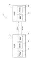
図1は、本実施の形態に係る画像データ転送システムGを示す。
画像データ転送システムGは、図1に示すように、送信装置g1及び受信装置g2を備え、送信装置g1から受信装置g2へ8ビットの画像データDを転送する。
送信装置g1は、例えば画像データを生成するプリントコントローラーであることができる。また、受信装置g2は、プリントコントローラーから送信された画像データに基づき、画像を形成するプリントエンジンであることができる。
送信装置g1と受信装置g2間は、専用線により接続されている。
FIG. 1 shows an image data transfer system G according to the present embodiment.
As shown in FIG. 1, the image data transfer system G includes a transmission device g1 and a reception device g2, and transfers 8-bit image data D from the transmission device g1 to the reception device g2.
The transmission device g1 can be, for example, a print controller that generates image data. The receiving device g2 can be a print engine that forms an image based on image data transmitted from the print controller.
The transmitter g1 and the receiver g2 are connected by a dedicated line.
送信装置g1は、画像データ生成部101、送信処理部102及びシリアル変換部103を備えている。なお、送信装置g1は、転送する画像データを入力する画像データ入力部を備えてもよい。
The transmission device g1 includes an image
画像データ生成部101は、ビットマップ形式の画像データDを生成する。例えば、画像データ生成部101は、ネットワーク上のコンピューター端末から送信されたPDL(Page Description Language)データをラスタライズ処理し、C(シアン)、M(マジェンタ)、Y(イエロー)、K(黒)の4色の画像データDを生成する。
また、画像データ生成部101は、画像データDの各画素の属性を示す属性データを生成し、画像データDとともに出力する。属性は、例えば文字(Text)、図形(Graphics)、写真(Image)である。
The image
Further, the image
送信処理部102は、画像データ生成部101から出力された画像データDをパケット単位で分割し、各パケットにエラー検出用データを付加して出力する。
エラー検出の方式としては特に限定されず、CRC(Cyclic Redundancy Check)、パリティチェック、チェックサム、ハミング符号等が挙げられる。CRCは、回路構成が簡易であることから好ましく、ここではCRCを用いた例を説明する。
The
The error detection method is not particularly limited, and examples include CRC (Cyclic Redundancy Check), parity check, checksum, and Hamming code. CRC is preferable because of its simple circuit configuration, and an example using CRC will be described here.
シリアル変換部103は、スクランブル回路を有している。
シリアル変換部103は、送信処理部102から出力された各パケットをシリアルデータに変換し、さらにスクランブル回路によりスクランブル処理して、受信装置g2に送信する。スクランブル処理により、画像データの転送に伴う不要輻射を防止することができる。シリアル変換部103は、パケットを送信する毎にスクランブル処理をリセットする。
The
The
受信装置g2は、図1に示すようにパラレル変換部201及び受信処理部202を備えている。
The receiving device g2 includes a
パラレル変換部201は、デスクランブル回路を有している。
パラレル変換部201は、送信装置g1から受信した各パケットをパラレルデータに変換し、さらにデスクランブル回路によりデスクランブル処理して、受信処理部202に出力する。パラレル変換部201は、パケットを受信する毎にデスクランブル処理をリセットする。
The
The
受信処理部202は、パラレル変換部201から出力された各パケットを連結して1ライン単位で画像データを出力する。この時、受信処理部202は、各パケットのエラーを検出し、送信装置g1に再送要求信号RETRY信号を送信する。
受信処理部202は、送信装置g1から再送されたパケットによりエラー訂正を行い、エラー訂正後の各パケットを連結して1ライン単位の画像データを出力する。
The
The
次に、送信処理部102及び受信処理部202の詳細を説明する。
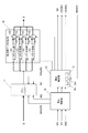
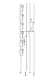
図2は、送信処理部102の構成図である。
図2に示すように、送信処理部102は、ラインバッファー11、書込制御部12、読出制御部13、検出用データ付加部14を備えている。
送信処理部102には、画像データDが、入力同期信号HV(Horizontal Valid)、VV(Vertical Valid)及びIND(INDex)とともに入力される。
Next, details of the
FIG. 2 is a configuration diagram of the
As shown in FIG. 2, the
Image data D is input to the
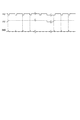
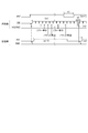
図3は、入力同期信号HV、VV及びINDを示している。
図3に示すように、入力同期信号HVは、アサート期間が主走査方向における画像の有効領域、すなわち各ラインの有効領域を示している。
また、入力同期信号VVは、図3に示すように、アサート期間が副走査方向における画像の有効領域、すなわち各ページの有効領域を示している。
入力同期信号INDは、各ラインの開始タイミングを示し、図3に示すように各ラインの開始タイミングのみアサートされている。
FIG. 3 shows the input synchronization signals HV, VV and IND.
As shown in FIG. 3, the input synchronization signal HV indicates the effective area of the image in the main scanning direction, that is, the effective area of each line.
Further, as shown in FIG. 3, the input synchronization signal VV indicates the effective area of the image in the sub-scanning direction, that is, the effective area of each page, as shown in FIG.
The input synchronization signal IND indicates the start timing of each line. As shown in FIG. 3, only the start timing of each line is asserted.
ラインバッファー11は、1ラインの画像データを保持できるメモリーである。
ラインバッファー11は、書込制御部12からイネーブル信号WE及び書込アドレスWADRSが入力されると、画像データDの1ラインを入力し、当該書込アドレスWADRSに対応付けて保持する。
また、ラインバッファー11は、読出制御部13からイネーブル信号RE及び読出アドレスRADRSが入力されると、当該読出アドレスRADRSに対応する画像データDを検出用データ付加部14に出力する。
The
When the enable signal WE and the write address WADRS are input from the
Further, when the enable signal RE and the read address RADRS are input from the read
書込制御部12は、入力同期信号HV及びVVに同期して、画像データDを1ライン単位でラインバッファー11に書き込む。
具体的には、入力同期信号HV及びVVが何れもアサート期間にあるとき、書込制御部12は、ラインバッファー11にイネーブル信号WEを出力し、ラインバッファー11への書き込みを許可する。
また、書込制御部12は、カウンターを用いて、1ラインの書込アドレスWADRSをラインバッファー11に出力する。1ラインが8000画素からなる場合、書込制御部12は、入力同期信号HV及びVVがアサート期間に切り替わると、カウンターにより0から1ずつカウントアップし、各カウント値を書込アドレスWADRSとして出力する。これにより、1ラインの先頭画素から順に、0〜7999の書込アドレスWADRSが割り当てられる。書込制御部12は、入力同期信号HVがネゲート期間に切り替わる毎に、カウンターを0にリセットする。
The
Specifically, when both the input synchronization signals HV and VV are in the assert period, the
Further, the
書込制御部12は、入力同期信号HV、VV及びINDを、読出制御部13に出力する。
The
読出制御部13は、ラインバッファー11に書き込まれた1ラインの画像データを、1ラインより小さいパケット単位で読み出す。1パケットは、2の累乗個の画素からなることが好ましい。
読み出し時、読出制御部13は、読出アドレスRADRSをラインバッファー11に出力し、パケット単位の画像データを読み出す。
The
At the time of reading, the
読出アドレスRADRSは、パケットのアドレスを上位ビットに、パケット内の画素のアドレスを下位ビットに配置して組み合わせたビット列である。
1パケットを128画素としたとき、8000画素からなる1ラインは、63パケットに分割される。この場合、各パケットのアドレス0〜62を上位6ビットに、パケット内の128画素のアドレス0〜127を下位7ビットに配置して組み合わせると、書込アドレスWADRSと同じ0〜7999の読出アドレスRADRSを構成することができる。
例えば、1ラインの先頭から300番目の画素は、書込アドレスWADRSが299である。1ラインをパケットに分割すると、300番目の画素は、3番目のパケット内の先頭から43番目に位置する。パケットのアドレスは2、パケット内の画素のアドレスは43である。2を上位6ビットに、43を下位7ビットに配置したビット列は、0000100101011であり、書込アドレスWADRSと同じ299を示している。
The read address RADRS is a bit string obtained by combining the address of the packet in the upper bits and the address of the pixels in the packet in the lower bits.
When one packet is 128 pixels, one line of 8000 pixels is divided into 63 packets. In this case, when the
For example, the write address WADRS is 299 for the 300th pixel from the beginning of one line. When one line is divided into packets, the 300th pixel is positioned 43rd from the beginning in the third packet. The address of the packet is 2, and the address of the pixel in the packet is 43. A bit string in which 2 is arranged in the upper 6 bits and 43 is arranged in the lower 7 bits is 0000100101011 and indicates the same 299 as the write address WADRS.
読出制御部13は、カウンターEv、Od及びCを備え、これらのカウント値を用いて読出アドレスRADRSを出力する。
2つのカウンターEv及びOdは、パケットが送信される毎に交互にカウントし、0〜62をカウントする。
カウンターCは、0〜130を繰り返しカウントする。
読出制御部13は、2つのカウンターEv及びOdにより得られたカウント値0〜62をパケットのアドレスとして用い、カウンターCにより得られたカウント値0〜127をパケット内の画素のアドレスとして用いて、読出アドレスRADRSを構成する。
The
The two counters Ev and Od alternately count each time a packet is transmitted, and count from 0 to 62.
The counter C repeatedly counts 0 to 130.
The
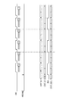
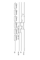
図4を参照して、2つのカウンターEv及びOdの基本的なカウント動作を説明する。
図4に示すDE(Data Enable)は、パケットの有効領域を示す出力同期信号である。また、HSYNCは、各ラインの開始タイミングを示す出力同期信号である。
読出制御部13は、カウンターEvとカウンターOdを交互にカウントさせるため、カウンターCが129をカウントする毎に、アサート期間とネゲート期間を切り替えるセレクト信号EOを出力する。
With reference to FIG. 4, the basic counting operation of the two counters Ev and Od will be described.
DE (Data Enable) shown in FIG. 4 is an output synchronization signal indicating an effective area of a packet. HSYNC is an output synchronization signal indicating the start timing of each line.
The
カウンターOdは、図4に示すようにセレクト信号EOがアサート期間へ切り替わると、カウントする。カウンターOdは、最初のカウント時、0のカウント値CNT_Oを出力し、次回以降のカウント時、もう一方のカウンターEvのカウント値CNT_Eに対して+1カウントして得られたカウント値CNT_Oを出力する。
カウンターEvは、図4に示すようにセレクト信号EOがネゲート期間へ切り替わると、カウントする。カウンターEvは、最初のカウント時、1のカウント値CNT_Eを出力し、次回以降のカウント時、もう一方のカウンターOdのカウント値CNT_Oに対して+1カウントして得られたカウント値CNT_Eを出力する。
各カウンターEv及びOdは、出力同期信号HSYNCがアサートされると、カウント値をリセットする。
The counter Od counts when the select signal EO switches to the assert period as shown in FIG. The counter Od outputs a count value CNT_O of 0 at the first count, and outputs a count value CNT_O obtained by counting +1 with respect to the count value CNT_E of the other counter Ev at the next count.
The counter Ev counts when the select signal EO switches to the negate period as shown in FIG. The counter Ev outputs a count value CNT_E of 1 at the first count, and outputs a count value CNT_E obtained by counting +1 with respect to the count value CNT_O of the other counter Od at the next count.
Each of the counters Ev and Od resets the count value when the output synchronization signal HSYNC is asserted.
読出制御部13は、図4に示すように、セレクト信号EOがアサート期間にあるとき、カウント値CNT_Oを選択し、セレクト信号EOがネゲート期間にあるとき、カウント値CNT_Eを選択する。これにより、パケットを読み出し、送信する毎に、0,1,2,3・・・62の昇順のカウント値CNT_SELが得られる。読出制御部13は、このカウント値CNT_SELをパケットのアドレスとして用いる。
As shown in FIG. 4, the
読出制御部13は、パケットの読み出しを、受信装置g2が1つ前のパケットのエラーを検出するのと並行して行う。1つ前のパケットにエラーが検出されると、読出制御部13は、パケットの読出中に再送要求信号RETRYを受信するので、読出中のパケットの次に、エラーが検出された1つ前のパケットを再度読み出す。
The
このとき、読出制御部13は、読み出し時のパケットのアドレスを1つ前に戻して、エラーが検出された1つ前のパケットを読み出す。受信装置g2が受信したパケットを書き込む時にも同じアドレス制御が行われるため、再送によりパケットを転送する順番が前後しても、受信装置g2は正しい順番でパケットを書き込むことができる。
具体的には、読出制御部13は、エラーフラグ信号EF及びフラグカウント信号EFCntを出力して、2つのカウンターEv及びOdのカウント動作を制御し、1つ前のパケットのアドレスを得る。
At this time, the
Specifically, the
読出制御部13は、図示しないカウンターを使用し、再送要求信号RETRYに応じて、エラーフラグ信号EF及びフラグカウント信号EFCntを出力する。
パケットのエラーは、パケットの最後に付加されたCRC符号により検出されるので、図5aに示すように、1つ前のパケットのエラーが検出されたとき、受信装置g2からの再送要求信号RETRYは、その次のパケットの読出中に入力される。
The
Since the packet error is detected by the CRC code added to the end of the packet, as shown in FIG. 5a, when the error of the previous packet is detected, the retransmission request signal RETRY from the receiving device g2 is , Input during reading of the next packet.
エラーフラグ信号EF用のカウンターは、再送要求信号RETRYが入力されると、+1カウントし、カウンターCが129をカウントすると、0にリセットする。
読出制御部13は、図5aに示すように、カウント値が1である間をアサート期間とし、0である間をネゲート期間とするエラーフラグ信号EFを出力する。
The counter for the error flag signal EF counts by +1 when the retransmission request signal RETRY is input, and resets to 0 when the counter C counts 129.
As shown in FIG. 5a, the
フラグカウント信号EFCnt用のカウンターは、何回連続してエラーフラグ信号EFがアサートされたかをカウントする。具体的には、当該カウンターは、カウンターCが128をカウントする時、エラーフラグ信号EFがアサートされていれば、+1カウントし、アサートされていなければ、0にリセットする。
読出制御部13は、図5aに示すように、カウント値が1である間をアサート期間とし、0である間をネゲート期間とするフラグカウント信号EFCntを出力する。
The counter for the flag count signal EFCnt counts how many times the error flag signal EF is asserted continuously. Specifically, when the counter C counts 128, the counter counts +1 if the error flag signal EF is asserted, and resets it to 0 if it is not asserted.
As shown in FIG. 5a, the
フラグカウント信号EFCnt用のカウンターは、下位1ビットを出力するカウンターである。
図5bに示すように、エラーフラグ信号EFが2回連続してアサートされると、+1+1=10のカウント値が得られるが、下位1ビットの0がカウント値として出力される。その結果、図5bに示すように、フラグカウント信号EFCntは、エラーフラグ信号EFの最初のアサートに応じてアサートされ、エラーフラグ信号EFの次のアサートに応じてネゲートされる。
エラーフラグ信号EFが3回連続してアサートされた場合、図5cに示すように、エラーフラグ信号EFがアサートされる毎に、フラグカウント信号EFCntはアサートとネゲートを繰り返す。
このように、フラグカウント信号EFCntは、エラーが複数回連続して発生すると、パケットが送信される毎にアサート期間とネゲート期間を繰り返す。
The counter for the flag count signal EFCnt is a counter that outputs the lower 1 bit.
As shown in FIG. 5b, when the error flag signal EF is continuously asserted twice, a count value of + 1 + 1 = 10 is obtained, but 0 of the lower 1 bit is output as the count value. As a result, as shown in FIG. 5b, the flag count signal EFCnt is asserted in response to the first assertion of the error flag signal EF and negated in response to the next assertion of the error flag signal EF.
When the error flag signal EF is continuously asserted three times, the flag count signal EFCnt repeats assertion and negation every time the error flag signal EF is asserted, as shown in FIG. 5c.
As described above, the flag count signal EFCnt repeats the assertion period and the negation period each time a packet is transmitted when an error occurs continuously a plurality of times.
カウンターEv及びOdは、カウント時、エラーフラグ信号EF及びフラグカウント信号EFCntをチェックし、各エラーフラグ信号EF及びフラグカウント信号EFCntに応じて、次のようにカウント動作する。
エラーが1回又は奇数回連続して検出された場合、検出直後はエラーフラグ信号EFがアサートされている。検出直後にカウントするカウンターEv又はOdはカウントを停止し、それぞれの直前のカウント値CNT_E又はCNT_Oを維持する。次のカウント時、エラーフラグ信号EFはネゲートされ、フラグカウント信号EFCntはアサートされている。このカウント時のカウンターEv又はOdは、各カウンターEv又はOd自身のカウント値CNT_E又はCNT_Oに対して+1カウントする。
The counters Ev and Od check the error flag signal EF and the flag count signal EFCnt at the time of counting, and perform a counting operation as follows according to each error flag signal EF and flag count signal EFCnt.
When an error is detected once or an odd number of times, the error flag signal EF is asserted immediately after detection. The counter Ev or Od that counts immediately after detection stops counting and maintains the count value CNT_E or CNT_O immediately before each. At the next count, the error flag signal EF is negated and the flag count signal EFCnt is asserted. The counter Ev or Od at this time counts +1 with respect to the count value CNT_E or CNT_O of each counter Ev or Od itself.
エラーが遇数回連続して検出された場合、検出直後はエラーフラグ信号EFがアサートされている。検出直後にカウントするカウンターEv又はOdはカウントを停止し、それぞれのカウント値CNT_E又はCNT_Oを維持する。次のカウント時、エラーフラグ信号EF及びフラグカウント信号EFCntがいずれもネゲートされている。このカウント時のカウンターEv又はOdは、もう一方のカウンターOd又はEvのカウント値CNT_O又はCNT_Eに対して+1カウントする。 When an error is detected consecutively several times, the error flag signal EF is asserted immediately after detection. The counter Ev or Od that counts immediately after detection stops counting and maintains the respective count value CNT_E or CNT_O. At the next count, both the error flag signal EF and the flag count signal EFCnt are negated. The counter Ev or Od at the time of counting is incremented by one with respect to the count value CNT_O or CNT_E of the other counter Od or Ev.
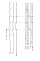
図6は、エラーが1回検出された場合の各カウンターEv及びOdのカウント動作を示すタイミングチャートである。
セレクト信号EOに従って、最初にカウンターOdが0をカウントする。次に、カウンターEvが1をカウントする。次に、カウンターOdがカウントするが、エラーが未検出であるので、カウンターOdはカウント値CNT_E=1に対して+1カウントする。図6中のpartner+1は、2つのカウンターEv及びOdが、もう一方のカウンターOd又はEvのカウント値に対してカウントすることを示している。
次のカウント時、エラーの検出直後であり、エラーフラグ信号EFがアサートされている。カウンターEvはカウント動作を停止し、直前のカウント値CNT_E=1を維持する。図6中のkeepは、カウント値を維持することを示している。
さらに次のカウント時、エラーフラグ信号EFはネゲートされているが、フラグカウント信号EFCntがアサートされている。そのため、カウンターOdは、カウンターOd自身の直前のカウント値CNT_O=2に対して+1カウントする。図6中のself+1は、カウンターEv又はOd自身のカウント値に対してカウントすることを示している。
FIG. 6 is a timing chart showing the counting operation of each counter Ev and Od when an error is detected once.
In accordance with the select signal EO, the counter Od first counts zero. Next, the counter Ev counts 1. Next, the counter Od counts, but since no error is detected, the counter Od counts +1 with respect to the count value CNT_E = 1. In FIG. 6, partner + 1 indicates that the two counters Ev and Od count with respect to the count value of the other counter Od or Ev.
At the next count, immediately after the error is detected, the error flag signal EF is asserted. The counter Ev stops the count operation and maintains the previous count value CNT_E = 1. Keep in FIG. 6 indicates that the count value is maintained.
At the next count, the error flag signal EF is negated, but the flag count signal EFCnt is asserted. Therefore, the counter Od counts +1 with respect to the count value CNT_O = 2 immediately before the counter Od itself. Self + 1 in FIG. 6 indicates that counting is performed with respect to the count value of the counter Ev or Od itself.
さらに次のカウント時、エラーが未検出であるので、エラーフラグ信号EF及びフラグカウント信号EFCntがネゲートされている。カウンターEvはカウント値CNT_O=3に対して+1カウントする。
結果として、カウンターEvからは1,1,4の順にカウント値CNT_Eが出力され、カウンターOdからは0,2,3の順にカウント値CNT_Oが出力される。
各カウント値CNT_E及びCNT_Oから選択されたカウント値CNT_SELは、0,1,2,1,3,4の順に出力される。このように、読出制御部13は、エラーが検出されると、次に出力するパケットのアドレスを、1つ前に出力したパケットのアドレスに戻して出力することができる。
Further, since no error is detected at the next count, the error flag signal EF and the flag count signal EFCnt are negated. The counter Ev counts +1 with respect to the count value CNT_O = 3.
As a result, the count value CNT_E is output in the order of 1, 1, 4 from the counter Ev, and the count value CNT_O is output in the order of 0, 2, 3 from the counter Od.
The count value CNT_SEL selected from the count values CNT_E and CNT_O is output in the order of 0, 1, 2, 1, 3, and 4. In this manner, when an error is detected, the
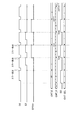
図7は、エラーが遇数回連続して検出された場合の各カウンターEv及びOdのカウント動作を示すタイミングチャートである。
先頭のパケットからエラーが2回連続して検出された場合、図7に示すように、エラーの検出直後のカウントの次のカウント時、エラーフラグ信号EF及びフラグカウント信号EFCntのいずれもがネゲートされている。この時カウントするカウンターOdは、もう一方のカウンターEvのカウント値CNT_Eに対して+1カウントする。
FIG. 7 is a timing chart showing the counting operations of the counters Ev and Od when an error is detected a number of times consecutively.
If an error is detected twice consecutively from the first packet, as shown in FIG. 7, both the error flag signal EF and the flag count signal EFCnt are negated at the time of the next count immediately after the error detection. ing. The counter Od that counts at this time counts +1 with respect to the count value CNT_E of the other counter Ev.
このようなカウント動作により、カウント値CNT_SELは、0,1,0,1,2,3の順となり、エラーが検出されたパケットのアドレス0,1が再度出力される。
By such a counting operation, the count value CNT_SEL is in the order of 0, 1, 0, 1, 2, and 3, and the
図8は、エラーが奇数回連続して発生した場合の各カウンターEv及びOdのカウント動作を示すタイミングチャートである。
先頭のパケットからエラーが3回連続して検出された場合、図8に示すように、3回目のエラー検出直後のカウントの次のカウント時、エラーフラグ信号EFはネゲートされているが、フラグカウント信号EFCntはアサートされている。このとき、カウントを行うカウンターEvは、自身のカウント値CNT_Eに対して+1カウントする。
FIG. 8 is a timing chart showing the counting operations of the counters Ev and Od when errors occur continuously for an odd number of times.
When an error is detected three times continuously from the first packet, as shown in FIG. 8, the error flag signal EF is negated at the next count after the third error detection, but the flag count The signal EFCnt is asserted. At this time, the counter Ev that performs counting counts +1 with respect to its own count value CNT_E.
このようなカウント動作により、カウント値CNT_SELは、0,1,0,1,0,2,3の順となり、エラーが検出されたパケットのアドレス0,1,0が再度出力される
By such a counting operation, the count value CNT_SEL is in the order of 0, 1, 0, 1, 0, 2, 3, and the
読出制御部13は、カウンターCのカウント値が0〜127の間、セレクター142に0のイネーブル信号を出力し、パケットの出力を許可する。また、読出制御部13は、カウント値が128のとき、1のイネーブル信号を出力し、CRC符号の出力を許可する。
The
読出制御部13は、パケット毎にスクランブル処理をリセットできるように、読み出すパケットの間隔をリセットに要する時間以上に長くすることが好ましい。
本実施の形態においては、リセットに2クロック要する。よって、読出制御部13は、上述のようにカウンターCにより128までカウントし、さらに129、130をカウントして2クロックの間隔をおいた後、カウント値をリセットして次のパケットを読み出している。
It is preferable that the
In this embodiment, two clocks are required for resetting. Therefore, the
読出制御部13は、各パケットの読み出し時、カウンターCのカウント値が0〜128の間をアサート期間とし、当該カウント値が129〜130の間をネゲート期間とする出力同期信号DEを生成し、出力する。すなわち、出力同期信号DEは、各パケットの有効領域を示している。
また、読出制御部13は、各パケットの読み出しに応じて、出力同期信号HSYNC及びVSYNCを生成し、出力する。出力同期信号HSYNCは各ラインの開始タイミングを示し、出力同期信号VSYNCは各ページの開始タイミングを示す。
When reading each packet, the
Further, the
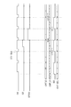
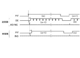
図9は、エラーの発生が無いときの入力同期信号HVと、送信装置g1が生成する出力同期信号DE及びHSYNCと、受信装置g2が生成する出力同期信号HV及びINDとを示している。
図9に示すように、出力同期信号DEは、入力同期信号HVより1ライン遅延している。入力同期信号HVがm番目のラインのアサート期間にあるとき、出力同期信号DEはm−1番目のラインの各パケットのアサート期間にある。出力同期信号HSYNCが示す各ラインの開始タイミングは、エラーの発生が無ければ、図9に示すように入力同期信号HVに同期する。
受信側の出力同期信号HV及びINDは、送信側の出力同期信号HSYNCに応じて生成され、図9に示すように受信側と送信側で各ラインの開始タイミングを同期させて、ライン同期させることができる。
FIG. 9 shows the input synchronization signal HV when no error occurs, the output synchronization signals DE and HSYNC generated by the transmission device g1, and the output synchronization signals HV and IND generated by the reception device g2.
As shown in FIG. 9, the output synchronization signal DE is delayed by one line from the input synchronization signal HV. When the input synchronization signal HV is in the assertion period of the mth line, the output synchronization signal DE is in the assertion period of each packet of the (m-1) th line. The start timing of each line indicated by the output synchronization signal HSYNC is synchronized with the input synchronization signal HV as shown in FIG. 9 if no error occurs.
The output synchronization signals HV and IND on the reception side are generated according to the output synchronization signal HSYNC on the transmission side, and the start timing of each line is synchronized between the reception side and the transmission side as shown in FIG. Can do.
読出制御部13は、パケットを再送する場合、図10に示すように、再送するパケットを含む1ラインの読み出しに、入力同期信号HVが示す当該ラインのアサート期間だけでなく、次のラインまでのネゲート期間t1も使用する。
図10に示すように、再送するパケットを含む1ラインの読み出しを、入力同期信号HVが示す次のラインの開始タイミングまでに終了できれば、元のライン周期がずれることも無く、受信側と送信側でライン同期を維持しながら、エラー訂正することができる。
When the packet is retransmitted, the
As shown in FIG. 10, if the reading of one line including the packet to be retransmitted can be completed by the start timing of the next line indicated by the input synchronization signal HV, the original line cycle is not shifted, and the receiving side and the transmitting side Thus, error correction can be performed while maintaining line synchronization.
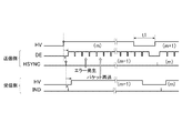
再送するパケットが多く、再送するパケットを含む1ラインの読み出しを、次のラインの開始タイミングまでに終了できなかった場合、図11に示すように、1ラインの終了タイミングが、入力同期信号HVが示す次のラインの開始タイミングを超える。この場合、読出制御部13は、図11に示すように1ラインの終了タイミングより後、例えば一定期間t2後に、出力同期信号HSYNCの次のラインの開始タイミングを遅延させる。
受信側では、図11に示すように出力同期信号HSYNCが示す開始タイミングに応じて出力同期信号HVが生成されるので、パケットの再送により元のライン周期にずれが生じても、受信側はライン同期を維持することができる。
When there are many packets to be retransmitted and reading of one line including the packet to be retransmitted cannot be completed by the start timing of the next line, as shown in FIG. 11, the end timing of one line is determined by the input synchronization signal HV. The start timing of the next line shown is exceeded. In this case, as shown in FIG. 11, the
On the receiving side, as shown in FIG. 11, the output synchronizing signal HV is generated in accordance with the start timing indicated by the output synchronizing signal HSYNC. Therefore, even if a deviation occurs in the original line period due to retransmission of the packet, the receiving side Synchronization can be maintained.
出力同期信号HSYNCの次のラインの開始タイミングを遅延させる場合、読出制御部13は、その後の各ラインの開始タイミングが入力同期信号HVと一致するまで、図11に示すように入力同期信号HVが示す各ライン間のネゲート期間t1を短縮し、各ラインを読み出す開始タイミングを早める。
これにより、パケットの再送によってずれたライン周期を、入力同期信号HVが示す本来のライン周期と一致させることができる。
When delaying the start timing of the next line of the output synchronization signal HSYNC, the
As a result, the line period shifted due to the retransmission of the packet can be matched with the original line period indicated by the input synchronization signal HV.
読出制御部13は、出力同期信号DEを検出用データ付加部14のCRC生成部141に出力する。
The
検出用データ付加部14は、C、M、Y、Kの各色用に、4セットのCRC生成部141及びセレクター142を備えている。ラインバッファー11から出力された各色のパケットが、各色に対するCRC生成部141に入力される。
CRC生成部141は、同期信号DEに同期して、ラインバッファー11から出力されたパケットを、セレクター142に出力する。また、CRC生成部141は、当該パケットからCRC符号を生成し、セレクター142に出力する。CRC符号はエラー検出用データであり、パケットのビット列を所定の生成多項式で除算したときの余りである。
The detection
The
セレクター142は、読出制御部13から0のイネーブル信号が入力されている間、検出用データ付加部14から出力されたパケットを出力する。セレクター142は、読出制御部13からのイネーブル信号が0から1に切り替わると、CRC符号を出力する。これにより、128画素の画像データにCRC符号が付加され、見かけ上129画素からなるパケットが出力される。
The
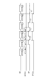
図12は、受信処理部202の構成図である。
図12に示すように、受信処理部202は、エラー検出部21、ラインバッファー22、書込制御部23、読出制御部24を備えて構成されている。
FIG. 12 is a configuration diagram of the
As shown in FIG. 12, the
エラー検出部21は、カウンター211、CRC生成部212、比較器213、OR回路214を備えている。CRC生成部212及び比較器213は、C、M、Y、Kの各色用に4セット設けられている。送信装置g1から受信した各色のパケットが、各色に対応するCRC生成部212に入力される。
The
カウンター211は、出力同期信号DEがアサートされると、0からカウントを開始し、出力同期信号DEがネゲートされると、カウント値を0にリセットする。これにより、0〜130のカウント値が順次比較器213に出力される。
The
CRC生成部212は、出力同期信号DEがアサート期間にあるとき、送信装置g1から受信したパケットを比較器213に出力する。
また、CRC生成部212は、受信したパケットの先頭から128画素の画像データによりCRC符号を生成して、比較器213に出力する。
When the output synchronization signal DE is in the assert period, the
The
カウンター211のカウント値が0から127までのとき、受信したパケットの先頭から128画素の画像データが、CRC生成部212から比較器213に入力される。比較器213は、当該画像データをラインバッファー22に出力する。
また、カウンター211のカウント値が128のとき、128画素の画像データに付加されたCRC符号がCRC生成部212から比較器213に入力される。比較器213は、当該CRC符号と、CRC生成部212により生成され、入力されたCRC符号とを比較し、一致か不一致かを示す比較結果をOR回路214に出力する。
OR回路214は、4つの比較器213のいずれかから、不一致の比較結果が入力されると、不一致を示す比較結果を書込制御部23に出力する。
When the count value of the
When the count value of the
When an unmatched comparison result is input from any of the four
ラインバッファー22は、1ラインの画像データを保持できるメモリーである。
ラインバッファー22は、書込制御部23からイネーブル信号WE及び書込アドレスWADRSが入力されると、当該書込アドレスWADRSに対応付けて、エラー検出部21から128画素のパケット単位で順次入力される画像データを保持する。
ラインバッファー11は、読出制御部24からイネーブル信号RE及び読出アドレスRADRSが入力されると、当該読出アドレスRADRSに対応する1ラインの画像データを出力する。
The
When the enable signal WE and the write address WADRS are input from the write control unit 23, the
When the enable signal RE and the read address RADRS are input from the read
エラーが検出された場合、パケットの再送により、先に保持している画像データと同じ書込アドレスWADRSの画像データが入力されるが、ラインバッファー22は、同じ書込アドレスWADRSで後から入力された画像データを上書きして保持する。
When an error is detected, image data having the same write address WADRS as the previously held image data is input by retransmission of the packet, but the
書込制御部23は、送信装置g1から受信した出力同期信号DEがアサート期間にあるとき、ラインバッファー22にイネーブル信号WEを出力し、ラインバッファー22への書き込みを許可する。
また、書込制御部23は、書込アドレスWADRSをラインバッファー22に出力し、ラインバッファー22にパケット単位で受信した画像データを書き込む。
When the output synchronization signal DE received from the transmission device g1 is in the assert period, the write control unit 23 outputs the enable signal WE to the
Further, the write control unit 23 outputs the write address WADRS to the
この書込アドレスWADRSは、送信装置g1の読出制御部13がパケットの読み出し時に用いた読出アドレスRADRSと同じく、パケットのアドレスを上位ビットに、パケット内の画素のアドレスを下位ビットに配置して組み合わせたビット列である。
これにより、読出制御部24が読み出し時に用いる0〜7999の読出アドレスRADRSと一致する書込アドレスWADRSを構成することができる。
書込制御部23は、読出制御部13と同じカウンターEv、Od及びCを備え、2つのカウンターEv及びOdによるカウント値をパケットのアドレス、カウンターCによるカウント値をパケット内の画素のアドレスとして用いる。各カウンターEv、Od及びCのカウント動作は、上述したとおりであるので、ここでは説明を省略する。
This write address WADRS is combined with the address of the packet in the upper bits and the address of the pixels in the packet in the lower bits, similar to the read address RADRS used by the
Thus, it is possible to configure the write address WADRS that matches the read address RADRS of 0 to 7999 used by the
The write control unit 23 includes the same counters Ev, Od, and C as the
書込制御部23は、パケットの書き込みを、1つ前のパケットのエラーの検出と並行して行う。エラーは、パケットの最後に付加されているCRC符号によって検出されるので、エラーが発生している場合、このパケットの書込中に、エラー検出部21から不一致の比較結果が入力される。書込制御部23が、再送要求信号RETRYを送信装置g1に送信すると、送信装置g1からエラーが検出された1つ前のパケットが再送される。書込制御部23は、書込中のパケットの次に、再送された1つ前のパケットをラインバッファー22に書き込む。
The write control unit 23 writes a packet in parallel with detection of an error in the previous packet. Since an error is detected by a CRC code added to the end of the packet, if an error has occurred, a mismatch comparison result is input from the
このとき、書込制御部23は、書き込み時のパケットのアドレスを1つ前に戻して、再送された1つ前のパケットを書き込む。再送によりパケットを転送する順番が前後するが、書込制御部23が送信装置g1の読出制御部13と同じアドレス制御を行うことにより、正しい順番でパケットを書き込むことができる。
具体的には、書込制御部23は、再送要求信号RETRYの送信に応じてエラーフラグ信号EF及びフラグカウント信号EFCntを出力し、2つのカウンターEv及びOdのカウント動作を制御して、1つ前のパケットのアドレスを得る。カウント動作の制御方法は、前述した読出制御部13と同じであり、前述したとおりであるので、ここでは詳細な説明を省略する。
At this time, the write control unit 23 returns the address of the packet at the time of writing to the previous one and writes the retransmitted one previous packet. Although the order in which packets are transferred by resending varies, the writing control unit 23 can write the packets in the correct order by performing the same address control as the
Specifically, the writing control unit 23 outputs an error flag signal EF and a flag count signal EFCnt in response to the transmission of the retransmission request signal RETRY, and controls the counting operation of the two counters Ev and Od to provide one. Get the address of the previous packet. The control method of the count operation is the same as that of the above-described
読出制御部24は、受信した出力同期信号HSYNC及びVSYNCに同期して、ラインバッファー22に書き込まれた各パケットを連結して読み出し、1ライン単位で画像データを出力する。具体的には、読出制御部24は、出力同期信号HSYNC又はVSYNCのいずれかがアサートされると、0〜7999を繰り返しカウントするカウンターのカウント値0〜7999を、読出アドレスRADRSとして順次出力する。
The
読出制御部24は、受信した出力同期信号HSYNC及びVSYNCから出力同期信号HV、VV及びINDを生成する。
具体的には、読出制御部24は、出力同期信号HSYNCがアサートされてから上記カウンターが0〜7999をカウントする間をアサート期間とし、カウント終了後、出力同期信号HSYNCが次にアサートされるまでをネゲート期間とする入力同期信号HVを生成する。
また、読出制御部24は、1ページの最初のラインの読み出しを開始してから、1ページ全てのラインの読み出しを終了するまでアサート期間とし、次のページの最初のラインの読み出しを開始するまでをネゲート期間とする出力同期信号VVを生成する。
また、読出制御部24は、出力同期信号HSYNCを出力同期信号INDとして出力する。
The
Specifically, the
Further, the
Further, the
上記画像データ転送システムGにおいて、送信装置g1から受信装置g2へ画像データを転送するときの処理手順を説明する。 In the image data transfer system G, a processing procedure when image data is transferred from the transmission device g1 to the reception device g2 will be described.
送信装置g1は、転送する画像データDを1ラインずつ送信処理部102によりパケット化し、各パケットにエラー検出用データを付加する。
まず、書込制御部12が、入力同期信号HV、VV及びINDに同期して画像データを1ライン入力し、ラインバッファー11に書き込む。
読出制御部13は、ラインバッファー11から1ラインの画像データをパケット単位で読み出す。また、読出制御部13は、各パケットの読み出しに応じて、出力同期信号DE、HSYNC及びVSYNCを生成して出力する。
検出用データ付加部14は、ラインバッファー11からパケット単位で読み出された画像データにエラー検出用データを付加して出力する。
The transmission device g1 packetizes the image data D to be transferred line by line by the
First, the
The
The detection
送信装置g1は、エラー検出用データが付加された各パケットを、シリアル変換部103によりシリアルデータに変換し、スクランブル処理して送信する。
受信装置g2は、送信装置g1から送信された各パケットを、パラレル変換部201によりパラレルデータに変換した後、デスクランブル処理する。
The transmission device g1 converts each packet to which the error detection data is added into serial data by the
The reception device g2 converts each packet transmitted from the transmission device g1 into parallel data by the
受信装置g2は、受信処理部202により、デスクランブル処理された各パケットを連結して1ラインの画像データを出力する。
まず、エラー検出部21が、デスクランブル処理された各パケットのエラーを検出する。
また、書込制御部23が、出力同期信号DE、HSYNC及びVSYNCに同期して、各パケットをラインバッファー22に書き込む。
エラーが検出されず、エラー訂正が無い場合、読出制御部24が、出力同期信号HSYNCに同期して、ラインバッファー22に書き込まれたパケットを連結して読み出し、1ラインの画像データを出力する。
The reception device g2 connects the packets descrambled by the
First, the
Further, the write control unit 23 writes each packet in the
When no error is detected and there is no error correction, the
エラーが検出され、エラー訂正が有る場合、書込制御部23がパケットの書込中に、1つ前のパケットのエラーが検出されるので、書込制御部23は再送要求信号RETRYを送信装置g1に送信する。
書込制御部23が書込中のパケットのアドレスをnとすると、送信装置g1では、読出制御部13がアドレスnのパケットの読出中に、再送要求信号RETRYを受信し、1つ前のパケットをラインバッファー11から読み出す。これにより、エラーが検出された1つ前のパケット(パケットのアドレスn−1)が、受信装置g2へ再送される。
If an error is detected and there is error correction, an error in the previous packet is detected while the write control unit 23 is writing the packet, so the write control unit 23 transmits a retransmission request signal RETRY. Send to g1.
Assuming that the address of the packet being written by the write control unit 23 is n, in the transmission device g1, the
受信装置g2では、書込制御部23が、書込中のパケット(パケットのアドレスn)の次に、再送された1つ前のパケット(パケットのアドレスn−1)をラインバッファー11に上書きし、エラー訂正する。読出制御部24は、ラインバッファー22に書き込まれた各パケットを連結して読み出し、1ラインの画像データを出力する。
In the receiving device g2, the write control unit 23 overwrites the
以上のように、本実施の形態によれば、画像データ転送システムGは、画像データを送信する送信装置g1と、当該画像データを受信する受信装置g2を備えている。送信装置g1は、ラインバッファー11と、入力同期信号HV、VV及びINDに同期して、画像データを1ライン単位でラインバッファー11に書き込む書込制御部12と、ラインバッファー11に書き込まれた画像データを、1ラインより小さいパケット単位で読み出すとともに、出力同期信号DE、HSYNC及びVSYNCを生成して受信装置g2に送信する読出制御部13と、読み出された各パケットに、エラー検出用データを付加して、受信装置g2に送信する検出用データ付加部14と、を備えている。受信装置g2は、送信装置g1から受信した各パケットのエラーを、各パケットに付加されているエラー検出用データを用いて検出するエラー検出部21と、ラインバッファー22と、受信した各パケットを、受信した出力同期信号DEに同期して、ラインバッファー22に書き込む書込制御部23と、送信装置g1から受信した出力同期信号HSYNC及びVSYNCに同期して、ラインバッファー22に書き込まれた各パケットを連結して読み出し、1ライン単位で画像データを出力する読出制御部24と、を備えている。受信装置g2の書込制御部23は、エラー検出部21によりパケットのエラーが検出されると、送信装置g1に再送要求信号を送信し、送信装置g1から再送されたパケットをラインバッファー22に書き込み、エラー訂正する。送信装置g1の読出制御部13は、再送要求信号に応じて、エラーが検出されたパケットをラインバッファー11から読み出し、検出用データ付加部14は、読み出されたパケットにエラー検出用データを付加して受信装置g2に再送する。
As described above, according to the present embodiment, the image data transfer system G includes the transmission device g1 that transmits image data and the reception device g2 that receives the image data. The transmission device g1 synchronizes with the
これにより、エラーが発生しても、1ラインより小さいパケット単位で再送し、エラー訂正することができ、画像データの転送率の低下を抑えて、正確にエラー訂正することができる。また、パケットが再送された場合も、出力同期信号によりライン同期させ、アドレス制御により1ラインのパケットの順番を維持することができる。従って、画像データの転送において、ライン同期を維持しながらエラー訂正することができる。 Thus, even if an error occurs, it can be retransmitted in units of packets smaller than one line and error correction can be performed, and the error correction can be accurately performed while suppressing a decrease in the transfer rate of image data. Also, even when a packet is retransmitted, line synchronization can be performed with an output synchronization signal, and the order of packets on one line can be maintained by address control. Therefore, error correction can be performed while maintaining line synchronization in the transfer of image data.
上記実施の形態は本発明の好適な一例であり、これに限定されない。本発明の主旨を逸脱しない範囲で適宜変更可能である。
例えば、上記実施の形態において、昇順の書込アドレスWADRS、RADRSを出力するため、カウントアップするカウンターEv、Od及びCの例を説明したが、カウントダウンするカウンターを用いて、降順の書込アドレスWADRS、RADRSを出力することもできる。
The above embodiment is a preferred example of the present invention, and the present invention is not limited to this. Modifications can be made as appropriate without departing from the spirit of the present invention.
For example, in the above-described embodiment, the example of the counters Ev, Od, and C that counts up in order to output the ascending write addresses WADRS and RADRS has been described. , RADRS can also be output.
また、ラインバッファー11及び22は、1ラインではなく、複数ラインの画像データを保持できるメモリーであってもよい。
1ラインがN個のパケットに分割される場合、1ライン分のメモリーがあれば、1ラインのアサート期間中に発生するN回のエラーまでエラー訂正することができる。よって、kラインの画像データを保持できるメモリーであれば、k×N回のエラー訂正が可能となる。
Further, the line buffers 11 and 22 may be memories that can hold image data of a plurality of lines instead of one line.
When one line is divided into N packets, if there is a memory for one line, errors can be corrected up to N errors that occur during the assertion period of one line. Therefore, if the memory can hold k lines of image data, k × N error corrections are possible.
また、転送する画像データは、圧縮された画像データであることができる。圧縮された画像データは、エラーによって復元できないことがあり、エラーの影響が大きい。上記画像データ転送システムGにより圧縮された画像データを転送すれば、圧縮された画像データを正確にエラー訂正することができ、好ましい。 Further, the image data to be transferred can be compressed image data. The compressed image data may not be restored due to an error, and the influence of the error is large. It is preferable to transfer the image data compressed by the image data transfer system G because the compressed image data can be accurately error-corrected.
また、読出制御部13及び書込制御部23は、エラーが検出された後、すぐにパケットが再送されるように、1つ前のパケットのアドレスに戻すアドレス制御を行っていたが、パケットのアドレスをいくつ前に戻すかは特に限定されない。例えば、2つ前のパケットのアドレスに戻すように、読出制御部13及び書込制御部23は、アドレス制御を行うこととしてもよい。
Further, the
また、エラーが1度発生すると、連続してエラーが発生することがあり、複数回のパケットの再送によって転送率が低下することがある。よって、エラーが発生した後、読出制御部13は、1パケットをさらに分割して1パケットより小さい単位で読み出すこととしてもよい。これにより、再送するデータサイズを減らすことができ、転送率の低下を抑えることができる。
In addition, once an error occurs, errors may occur continuously, and the transfer rate may decrease due to multiple retransmissions of packets. Therefore, after an error occurs, the
G 画像データ転送システム
g1 送信装置
102 送信処理部
11 ラインバッファー
12 書込制御部
13 読出制御部
Ev カウンター
Od カウンター
C カウンター
14 検出用データ付加部
103 シリアル変換部
g2 受信装置
201 パラレル変換部
202 受信処理部
21 エラー検出部
22 ラインバッファー
23 書込制御部
Ev カウンター
Od カウンター
C カウンター
24 読出制御部
G image data transfer system
Claims (10)
前記送信装置は、
ラインバッファーと、
入力同期信号に同期して、書込アドレスを前記ラインバッファーに出力し、前記ラインバッファーに1ライン単位で画像データを書き込む書込制御部と、
前記ラインバッファーに読出アドレスを出力し、書き込まれた画像データを1ラインより小さいパケット単位で読み出すとともに、出力同期信号を生成する読出制御部と、
前記読み出された各パケットにエラー検出用データを付加する検出用データ付加部と、を備え、各パケットを出力同期信号とともに送信し、
前記受信装置は、
前記送信装置から受信した各パケットのエラーを、各パケットに付加されているエラー検出用データを用いて検出するエラー検出部と、
ラインバッファーと、
前記送信装置から受信した出力同期信号に同期して、前記ラインバッファーに書込アドレスを出力し、前記受信した各パケットを前記ラインバッファーに書き込む書込制御部と、
前記受信した出力同期信号に同期して、前記ラインバッファーに読出アドレスを出力し、書き込まれた各パケットを連結して読み出して1ライン単位で画像データを出力する読出制御部と、を備え、
前記受信装置の書込制御部は、前記エラー検出部によりパケットのエラーが検出されると、前記送信装置に再送要求信号を送信し、前記書込アドレスを戻して前記送信装置から再送されたパケットを前記ラインバッファーに書き込み、エラー訂正し、
前記送信装置の読出制御部は、前記再送要求信号に応じて、前記読出アドレスを戻して前記エラーが検出されたパケットを前記ラインバッファーから読み出し、再送する、
画像データ転送システム。 A transmission device that transmits image data, and a reception device that receives the image data;
The transmitter is
A line buffer;
A write controller that outputs a write address to the line buffer in synchronization with an input synchronization signal and writes image data to the line buffer in units of one line;
A read control unit that outputs a read address to the line buffer, reads the written image data in units of packets smaller than one line, and generates an output synchronization signal;
A detection data adding unit for adding error detection data to each read packet, and transmitting each packet together with an output synchronization signal;
The receiving device is:
An error detection unit that detects an error of each packet received from the transmission device using error detection data attached to each packet;
A line buffer;
A write control unit that outputs a write address to the line buffer in synchronization with the output synchronization signal received from the transmitter, and writes each received packet to the line buffer;
A read control unit that outputs a read address to the line buffer in synchronization with the received output synchronization signal, concatenates and reads the written packets, and outputs image data in units of one line;
When a packet error is detected by the error detector, the write controller of the receiver transmits a retransmission request signal to the transmitter, returns the write address, and is retransmitted from the transmitter To the line buffer, error correction,
In response to the retransmission request signal, the reading control unit of the transmitting device returns the reading address and reads the packet in which the error is detected from the line buffer and retransmits the packet.
Image data transfer system.
請求項1に記載の画像データ転送システム。 When retransmitting a packet, the reading control unit of the transmitting apparatus uses an assertion period of one line indicated by the input synchronization signal and a negation period until the next line for reading one line including the packet to be retransmitted. ,
The image data transfer system according to claim 1.
請求項1又は2に記載の画像データ転送システム。 When the end timing of one line including the packet to be retransmitted exceeds the start timing of the next line indicated by the input synchronization signal, the reading control unit of the transmission device may receive the next of the output synchronization signal after the end timing. Delay the start of the line,
The image data transfer system according to claim 1 or 2.
請求項3に記載の画像データ転送システム。 When the read control unit of the transmission device delays the start timing of the next line of the output synchronization signal, each line indicated by the input synchronization signal until the start timing of each subsequent line coincides with the input synchronization signal. Shorten the negation period between them, and advance the timing to read each line,
The image data transfer system according to claim 3.
前記受信装置の書込制御部は、パケットの書き込みを、1つ前のパケットのエラーの検出と並行して行い、1つ前のパケットにエラーが検出されると前記再送要求信号を送信し、書込中のパケットの次に、前記送信装置から再送された1つ前のパケットを書き込む、
請求項1〜4のいずれか一項に記載の画像データ転送システム。 The reading control unit of the transmitting apparatus performs the reading of the packet in parallel with the detection of the error of the previous packet, and when an error is detected in the previous packet and a retransmission request signal is received, Next to the packet, read the previous packet in which an error was detected,
The write control unit of the receiving device performs packet writing in parallel with detection of an error of the previous packet, and transmits the retransmission request signal when an error is detected in the previous packet, Next to the packet being written, the previous packet retransmitted from the transmitter is written.
The image data transfer system according to any one of claims 1 to 4.
前記送信装置の読出制御部は、前記パケットのアドレスを1つ前に戻して、前記エラーが検出された1つ前のパケットを読み出し、
前記受信装置の書込制御部は、前記パケットのアドレスを1つ前に戻して、前記再送された1つ前のパケットを書き込む、
請求項5に記載の画像データ転送システム。 The read address and the write address are a bit string obtained by combining the address of the packet in the upper bits and the address of the pixels in the packet in the lower bits,
The reading control unit of the transmitting device returns the address of the packet to the previous one, reads the previous packet in which the error was detected,
The write control unit of the receiving device writes the retransmitted previous packet by returning the address of the packet to the previous one,
The image data transfer system according to claim 5.
前記2つのカウンターは、
エラーが未検出の場合、各カウンターはもう一方のカウンターのカウント値に対してカウントし、
エラーが1回又は奇数回連続して検出された場合、検出直後にカウントするカウンターはカウントを停止してカウント値を維持し、次にカウントするカウンターは自身のカウント値に対してカウントし、
エラーが遇数回連続して検出された場合、検出直後にカウントするカウンターはカウントを停止してカウント値を維持し、次にカウントするカウンターはもう一方のカウンターのカウント値に対してカウントする、
請求項6に記載の画像データ転送システム。 The reading control unit of the transmitting device and the writing control unit of the receiving device include two counters that alternately count each time a packet is transmitted, and use the count value by the two counters as the address of the packet,
The two counters are
If no error is detected, each counter counts against the count value of the other counter,
If an error is detected once or an odd number of times consecutively, the counter that counts immediately after detection stops counting and maintains the count value, and the next counter that counts counts against its own count value,
If an error is detected a number of times consecutively, the counter that counts immediately after detection stops counting and maintains the count value, and the next counter that counts counts against the count value of the other counter.
The image data transfer system according to claim 6.
前記受信装置は、前記受信したパケットをデスクランブル処理し、パラレルデータに変換するパラレル変換部を備える、
請求項1〜7のいずれか一項に記載の画像データ転送システム。 The transmission device includes a serial conversion unit that converts the packet into serial data, scrambles and transmits the data,
The receiving device includes a parallel conversion unit that descrambles the received packet and converts the packet into parallel data.
The image data transfer system according to claim 1.
請求項8に記載の画像データ転送システム。 The reading control unit of the transmitting device makes the interval between the packets to be read longer than the time required for resetting the scramble process,
The image data transfer system according to claim 8.
請求項1〜9のいずれか一項に記載の画像データ転送システム。 The image data is compressed image data.
The image data transfer system according to claim 1.
Priority Applications (1)
| Application Number | Priority Date | Filing Date | Title |
|---|---|---|---|
| JP2012277609A JP6107119B2 (en) | 2012-12-20 | 2012-12-20 | Image data transfer system |
Applications Claiming Priority (1)
| Application Number | Priority Date | Filing Date | Title |
|---|---|---|---|
| JP2012277609A JP6107119B2 (en) | 2012-12-20 | 2012-12-20 | Image data transfer system |
Publications (2)
| Publication Number | Publication Date |
|---|---|
| JP2014123792A true JP2014123792A (en) | 2014-07-03 |
| JP6107119B2 JP6107119B2 (en) | 2017-04-05 |
Family
ID=51403975
Family Applications (1)
| Application Number | Title | Priority Date | Filing Date |
|---|---|---|---|
| JP2012277609A Active JP6107119B2 (en) | 2012-12-20 | 2012-12-20 | Image data transfer system |
Country Status (1)
| Country | Link |
|---|---|
| JP (1) | JP6107119B2 (en) |
Cited By (1)
| Publication number | Priority date | Publication date | Assignee | Title |
|---|---|---|---|---|
| CN119697335A (en) * | 2024-12-19 | 2025-03-25 | 电子科技大学 | An FPGA hardware error correction structure for optical fiber transmission of Bayer images |
Citations (5)
| Publication number | Priority date | Publication date | Assignee | Title |
|---|---|---|---|---|
| JPH01164167A (en) * | 1987-12-21 | 1989-06-28 | Ricoh Co Ltd | facsimile machine |
| JPH01248844A (en) * | 1988-03-30 | 1989-10-04 | Fuji Photo Film Co Ltd | Data transmission system |
| JPH0556206A (en) * | 1991-08-26 | 1993-03-05 | Canon Inc | Image communication device |
| US20060064625A1 (en) * | 2004-09-20 | 2006-03-23 | Alcatel | Extended repeat request scheme for mobile communication networks |
| JP2008079330A (en) * | 2005-01-28 | 2008-04-03 | Sharp Corp | Communication device, communication method, communication program, communication circuit, mobile phone, display device, printing device, recording device |
-
2012
- 2012-12-20 JP JP2012277609A patent/JP6107119B2/en active Active
Patent Citations (5)
| Publication number | Priority date | Publication date | Assignee | Title |
|---|---|---|---|---|
| JPH01164167A (en) * | 1987-12-21 | 1989-06-28 | Ricoh Co Ltd | facsimile machine |
| JPH01248844A (en) * | 1988-03-30 | 1989-10-04 | Fuji Photo Film Co Ltd | Data transmission system |
| JPH0556206A (en) * | 1991-08-26 | 1993-03-05 | Canon Inc | Image communication device |
| US20060064625A1 (en) * | 2004-09-20 | 2006-03-23 | Alcatel | Extended repeat request scheme for mobile communication networks |
| JP2008079330A (en) * | 2005-01-28 | 2008-04-03 | Sharp Corp | Communication device, communication method, communication program, communication circuit, mobile phone, display device, printing device, recording device |
Cited By (1)
| Publication number | Priority date | Publication date | Assignee | Title |
|---|---|---|---|---|
| CN119697335A (en) * | 2024-12-19 | 2025-03-25 | 电子科技大学 | An FPGA hardware error correction structure for optical fiber transmission of Bayer images |
Also Published As
| Publication number | Publication date |
|---|---|
| JP6107119B2 (en) | 2017-04-05 |
Similar Documents
| Publication | Publication Date | Title |
|---|---|---|
| JP5233165B2 (en) | Data transmission device | |
| CN202889529U (en) | Image outputting apparatus, image processing apparatus and imaging apparatus | |
| US10362220B2 (en) | Conversation of pixel data into compression format of pixels | |
| US10129371B2 (en) | Serial communication device and serial communication method | |
| US8699494B2 (en) | Image transfer apparatus, method, and computer readable medium | |
| JP5377040B2 (en) | Transmitting apparatus and transmitting method | |
| JP2014138344A (en) | Image data transfer system | |
| JP5293860B1 (en) | Serial communication system, image forming system, and transmission apparatus | |
| JP6107119B2 (en) | Image data transfer system | |
| US8621314B2 (en) | Transmitting and receiving system and method, and non-transitory computer readable medium | |
| JP6668964B2 (en) | Image forming system, image data transmission unit, and image data transmission method | |
| JP2016111672A (en) | Communication method, communication system, and communication device | |
| CN114600467A (en) | Transmission device, reception device, and transmission system | |
| CN102334331A (en) | Serial data transmission-reception device and digital camera | |
| JP6362826B2 (en) | Image data transfer system | |
| JP2015125606A (en) | Transmission circuit | |
| JP6172355B2 (en) | Transmission / reception system and program | |
| JP7571403B2 (en) | Transmitting device, receiving device, transmitting/receiving device, transmitting program, receiving program, transmitting/receiving program, and image processing device | |
| JP7725240B2 (en) | Serial communication device and serial communication method | |
| US20170063521A1 (en) | Serial communication apparatus, communication system, and method for communication | |
| JP6414702B2 (en) | Image processing device | |
| CN102457761B (en) | For the method and apparatus sending and receiving video flowing | |
| JP2010288014A (en) | Image transfer device, image reader, and image forming device | |
| WO2017183706A1 (en) | Multiplexer and image capturing device provided with said multiplexer | |
| JP2017204738A (en) | Data transmitting apparatus, data receiving apparatus, data transmitting / receiving method, and information processing apparatus |
Legal Events
| Date | Code | Title | Description |
|---|---|---|---|
| A621 | Written request for application examination |
Free format text: JAPANESE INTERMEDIATE CODE: A621 Effective date: 20150710 |
|
| A977 | Report on retrieval |
Free format text: JAPANESE INTERMEDIATE CODE: A971007 Effective date: 20160526 |
|
| A131 | Notification of reasons for refusal |
Free format text: JAPANESE INTERMEDIATE CODE: A131 Effective date: 20160614 |
|
| TRDD | Decision of grant or rejection written | ||
| A01 | Written decision to grant a patent or to grant a registration (utility model) |
Free format text: JAPANESE INTERMEDIATE CODE: A01 Effective date: 20170207 |
|
| A61 | First payment of annual fees (during grant procedure) |
Free format text: JAPANESE INTERMEDIATE CODE: A61 Effective date: 20170220 |
|
| R150 | Certificate of patent or registration of utility model |
Ref document number: 6107119 Country of ref document: JP Free format text: JAPANESE INTERMEDIATE CODE: R150 |