JP2014122957A - Imaging device - Google Patents
Imaging device Download PDFInfo
- Publication number
- JP2014122957A JP2014122957A JP2012277813A JP2012277813A JP2014122957A JP 2014122957 A JP2014122957 A JP 2014122957A JP 2012277813 A JP2012277813 A JP 2012277813A JP 2012277813 A JP2012277813 A JP 2012277813A JP 2014122957 A JP2014122957 A JP 2014122957A
- Authority
- JP
- Japan
- Prior art keywords
- image
- image sensor
- pixel
- focus detection
- photoelectric conversion
- Prior art date
- Legal status (The legal status is an assumption and is not a legal conclusion. Google has not performed a legal analysis and makes no representation as to the accuracy of the status listed.)
- Pending
Links
Images


Abstract
Description
本発明は、撮像装置の動画撮影中のオートフォーカスと静止画撮影の技術に関し、特に撮像素子を複数持つ撮像装置に関するものである。 The present invention relates to an autofocus and still image shooting technique during moving image shooting of an image pickup apparatus, and more particularly to an image pickup apparatus having a plurality of image pickup elements.
従来、画像を撮影する撮像素子と位相差AF(オートフォーカス)をするためのAFセンサを備え、動画撮影中に位相差AFを行う技術がある。特許文献1では、ハーフミラーで撮像素子とAFセンサに被写体像を入射し、撮像素子で撮影した動画を表示しながら位相差AFをする技術が開示されている。 2. Description of the Related Art Conventionally, there is a technology that includes an image sensor that captures an image and an AF sensor that performs phase difference AF (autofocus), and performs phase difference AF during moving image shooting. Japanese Patent Application Laid-Open No. 2004-228561 discloses a technique for performing phase difference AF while a subject image is incident on an image sensor and an AF sensor with a half mirror and a moving image captured by the image sensor is displayed.
しかしながら、上述の特許文献1に開示された技術では、静止画を撮影する時には動画を停止し、静止画撮影終了後に動画を再開する必要がある。また、静止画と動画を同時に出力する撮像素子を使用しようとする場合、処理速度や回路構成が増大してしまうことになる。そこで、本発明の目的は、動画撮影中にAFを行い、かつ動画撮影を中断することなく静止画を撮影することを可能にした撮像装置を提供することである。
However, with the technique disclosed in
上記目的を達成するために、本発明の撮像装置は次の特徴を有する。
光電変換部を含む画素が2次元に配置されている第1の撮像素子と、光電変換部を含む画素が2次元に配置されている第2の撮像素子と、共通光学系に入射された光束を前記第1の撮像素子と前記第2の撮像素子にそれぞれ入射させる光分割手段と、前記第2の撮像素子の画素からの信号に基づいて焦点検出を行う焦点検出手段と、前記焦点検出手段の検出結果に基づいて前記共通光学系の焦点位置を変更する焦点位置変更手段と、前記第1の撮像素子の画素からの信号と前記第2の撮像素子の画素からの信号を処理する画像処理手段と、を備える。そして、前記第2の撮像素子は、前記共通光学系の射出瞳の第1の領域を通って瞳分割された光束を受光するための第1の光電変換部、又は/及び、前記共通光学系の射出瞳の第1の領域からずれた第2の領域を通って瞳分割された光束を受光するための第2の光電変換部を含む焦点検出用画素を持ち、前記第1の撮像素子と前記第2の撮像素子に前記共通光学系で像が結像される様に、前記第1の撮像素子と前記第2の撮像素子と前記光分割手段が配置され、前記第1の撮像素子の画素からの信号と前記第2の撮像素子の画素からの信号が、それぞれ、前記画像処理手段で独立に処理される。
In order to achieve the above object, the imaging apparatus of the present invention has the following characteristics.
A first imaging element in which pixels including a photoelectric conversion unit are two-dimensionally arranged, a second imaging element in which pixels including a photoelectric conversion unit are two-dimensionally arranged, and a light beam incident on a common optical system Splitting the light into the first image sensor and the second image sensor, focus detection means for performing focus detection based on signals from the pixels of the second image sensor, and the focus detection means Focus position changing means for changing the focus position of the common optical system based on the detection result of the first image processing, and image processing for processing signals from the pixels of the first image sensor and signals from the pixels of the second image sensor Means. Then, the second image sensor is a first photoelectric conversion unit for receiving a light beam divided through the first region of the exit pupil of the common optical system, and / or the common optical system. A focus detection pixel including a second photoelectric conversion unit for receiving a light beam divided through the second region shifted from the first region of the exit pupil of the first pupil; and The first image sensor, the second image sensor, and the light splitting unit are arranged so that an image is formed on the second image sensor by the common optical system. Signals from the pixels and signals from the pixels of the second image sensor are each independently processed by the image processing means.
本発明によれば、動画撮影中にAFを行い、かつ動画撮影を中断することなく静止画を撮影することを可能にした撮像装置を提供することができる。 According to the present invention, it is possible to provide an imaging apparatus that performs AF during moving image shooting and can capture a still image without interrupting moving image shooting.
本発明の撮像装置では、共通の結像光学系により像が結像される様に、画素を含む第1の撮像素子と焦点検出用画素を含む第2の撮像素子が配置され、第1及び第2の撮像素子の画素からの信号が、それぞれ、画像処理手段で独立に処理される。これにより、例えば、複数の撮像素子を同じ像面倍率になる様に光分割手段とともに配置し、それぞれの撮像素子で静止画、動画を独立に撮影するようにして、動画を出力する撮像素子の出力を用いて焦点検出を行い、AF動作を同時に行うようなことができる。従って、動画撮影中にAFを行い、かつ動画撮影を中断することなく静止画を撮影することが可能となる。 In the imaging apparatus of the present invention, the first imaging element including the pixels and the second imaging element including the focus detection pixels are arranged so that the image is formed by the common imaging optical system. Signals from the pixels of the second image sensor are each independently processed by the image processing means. Thereby, for example, a plurality of image sensors are arranged together with the light splitting means so as to have the same image plane magnification, and still images and moving images are independently photographed by the respective image sensors, so that an image sensor that outputs moving images is used. Focus detection is performed using the output, and AF operation can be performed simultaneously. Therefore, AF can be performed during moving image shooting, and a still image can be shot without interrupting moving image shooting.
以下に、本発明の実施の形態を、添付の図面に基づいて詳細に説明する。
(実施形態1)
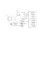
図1は、本発明の実施形態に係る撮像装置の構成を示すブロック図である。図1を参照して、本発明の第1の実施形態による撮像装置の構成、動作について説明する。図1の撮像装置において、100は、光学像を電気信号に変換する第1の撮像素子である。撮像素子100では主に静止画を撮影する。101は、撮像素子100から出力されたアナログの画像信号に対して、ゲイン調整や所定の量子化ビットに対応してデジタル変換を行うアナログフロントエンド(以下、これをAFEと称する)である。102は、撮像素子100及びAFE101の駆動タイミングを制御するタイミングジェネレータ(以下、これをTGと称する)である。103は、光学像を電気信号に変換する第2の撮像素子である。撮像素子103では主に動画を撮影する。104は、撮像素子103から出力されたアナログの画像信号に対して、ゲイン調整や所定の量子化ビットに対応してデジタル変換を行うAFEである。105は、撮像素子103及びAFE104の駆動タイミングを制御するTGである。本実施形態では第1の撮像素子100に関連するAFE101、TG102や、第2の撮像素子103に関連するAFE104、TG105が使用されているが、AFE、TGは撮像素子内に内蔵される構成も可能である。
Embodiments of the present invention will be described below in detail with reference to the accompanying drawings.
(Embodiment 1)
FIG. 1 is a block diagram illustrating a configuration of an imaging apparatus according to an embodiment of the present invention. With reference to FIG. 1, the configuration and operation of an imaging apparatus according to the first embodiment of the present invention will be described. In the imaging apparatus of FIG. 1,
118はRAMである。RAMは、AFE101、AFE104でデジタル変換された画像データや、後述の画像処理部120または画像処理部121で処理された画像データを記憶する画像データ記憶手段の機能と、後述のCPU124が動作を行う際のワークメモリの機能を兼備する。本実施形態では、これらの機能を、RAM118を用いて行うようにしているが、アクセス速度が十分に問題ないレベルのメモリであれば、他のメモリを適用することも可能である。119は、CPU124が動作を行う際のプログラムを格納するROMである。ここで、本実施形態では、Flash−ROMを示すが、これは一例であり、アクセス速度が十分に問題ないレベルのメモリであれば、他のメモリを適用することも可能である。124は、撮像装置を統括的に制御するCPUである。120は、撮影された後述の静止画の補正・圧縮等の処理を行う画像処理部である。121は、撮影された後述の動画の補正・圧縮等の処理を行う画像処理部である。また、後述するA画像データとB画像データを加算する機能を備える。この様に、第1の撮像素子の画素からの信号と第2の撮像素子の画素からの信号が、それぞれ、画像処理手段で独立に処理され、画像が生成される。
Reference numeral 118 denotes a RAM. The RAM functions as an image data storage unit that stores the image data digitally converted by the AFE 101 and the AFE 104 and the image data processed by the
122は、第2の撮像素子103から出力された画素信号から焦点検出を行うAF演算部である。123は、静止画データ及び動画データを記録するための、着脱可能なフラッシュメモリである。本実施形態では、記録媒体としてフラッシュメモリを適用しているが、その他のデータ書き込み可能な不揮発メモリ、ハードディスク等でもよい。また、これらの記録媒体を内蔵した形態でもよい。116は、撮影命令や撮影条件等の設定をCPU124に対して行う操作部である。117は、撮影した静止画像や動画像、メニュー等の表示を行う表示部である。
111は、撮影光学系(共通光学系)の先端に配置された第1レンズ群で、光軸方向に進退可能に保持される。110は絞りで、その開口径を調節することで撮影時の光量調節を行う。109は第2レンズ群である。そして、前記絞り110及び第2レンズ群109は一体となって光軸方向に進退し、前記第1レンズ群111の進退動作との連動により、変倍作用(ズーム機能)をなす。108は第3レンズ群で、光軸方向の進退により、焦点調節を行う。107は、入射された被写体からの光束を反射光と透過光に分割するハーフミラーである。ハーフミラー107の反射光は第2の撮像素子103に入射し、透過光は第1の撮像素子100に入射される。
106は、静止画撮影時に露光秒時を調節するフォーカルプレーンシャッタである。本実施形態では、フォーカルプレーンシャッタにて撮像素子100の露光秒時を調節する構成であるが、この限りではない。撮像素子100が電子シャッタ機能を有し、制御パルスで露光秒時を調節する構成でもよい。112は、光学系の焦点位置を変更する焦点位置変更手段であるフォーカス駆動回路で、AF演算部122の焦点検出結果に基づいてフォーカスアクチュエータ114を駆動制御し、第3レンズ群108を光軸方向に進退駆動して焦点調節を行なう。113は絞り駆動回路で、絞りアクチュエータ115を駆動制御して絞り110の開口を制御する。
A
図2は、第1の撮像素子100、第2の撮像素子103、ハーフミラー107の位置を示した図である。前述した様に、ハーフミラー107の反射光は撮像素子103に入射され透過光は撮像素子100に入射される位置・角度にハーフミラー107は配置される。つまり、第1の撮像素子は、光分割手段の透過光が入射され、第2の撮像素子は、光分割手段の反射光が入射される。ハーフミラー107の中心から撮像素子100までの距離aと、撮像素子103までの距離bは等しく配置される。これにより、第1の撮像素子100と第2の撮像素子103には、等しい倍率の被写体像である一次結像が入射される。この構成により、第2の撮像素子103の画像信号を用いてAF動作を行った場合でも、第1の撮像素子100に結像する像の焦点を合わせることができる。
FIG. 2 is a diagram illustrating the positions of the
次に第1の撮像素子100について説明する。図3に撮像素子100の構成を示す。図3において、撮像素子は、画素アレイ100aと、画素アレイ100aにおける行を選択する垂直選択回路100d、画素アレイ100aにおける列を選択する水平選択回路100cを持つ。また、画素アレイ100a中の画素のうち垂直選択回路100d及び水平選択回路100cによって選択される画素の信号を読み出す読み出し回路100bを備える。垂直選択回路100dは、画素アレイ100aの行を選択し、CPU124から出力される水平同期信号に基づいたTG102から出力される読出しパルスを、選択行において有効にする。読出し回路100bは列毎のアンプやメモリを含み、選択行の画素信号はアンプを介してメモリに格納される。メモリに格納された1行分の画素信号は、水平選択回路100cによって列方向に順に選択され、アンプ100eを介して外部に出力される。この動作を行数分繰り返し、全ての画素の信号を外部に出力する。
Next, the
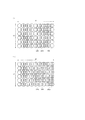
図4(a)に画素アレイ100aの構成を示す。第1の撮像素子100の画素アレイ100aは、2次元の画像を提供するために、複数の画素を2次元アレイ状に配列して構成される。図4(a)において、100fはマイクロレンズであり、100gは光電変換を行うフォトダイオード(PD)である。各画素、PD1つに対して1つのマイクロレンズ100fが上部に配置される構成となっている。この画素が、水平方向にh1画素、垂直方向にi1画素並んで配置される。
FIG. 4A shows the configuration of the
第2の撮像素子103の構成と読出し動作は、図3に示す第1の撮像素子100の構成と同様であるため、説明を省略する。撮像素子103の画素アレイを図4(b)に示す。図4(b)において、103fはマイクロレンズであり、103g、103hはPDである。各画素、PD2つに対して1つのマイクロレンズ103fが上部に配置される構成となっている。すなわち、焦点検出用画素は、1つのマイクロレンズに対して複数の光電変換部を備える。マイクロレンズ103fが共有されている領域を1画素とした場合、この画素が水平方向にh2画素、垂直方向にi2画素並んで配置される。PD103gとPD103hで蓄積された信号は、前述した読出し動作によって別々に外部に出力される。PD103gとPD103hは、後述する構成により位相差を持った別の像が入射されるため、ここではPD103gをA像用光電変換部、PD103hをB像用光電変換部とする。なお、本実施形態ではマイクロレンズ1つに対してPDが2つ配置される構成であるがこの限りではない。マイクロレンズ1つに対してPDが上下または左右に複数配置される構成であれば適用することができる。
The configuration and reading operation of the
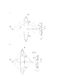
次に第2の撮像素子103のA像用光電変換部とB像用光電変換部が出力する画像データについて説明する。図5(a)と図5(b)は、撮像素子103におけるピント状態と位相差との関係を示す。103aは画素アレイの断面を示す。128は前述したマイクロレンズ、129、130はそれぞれA像用光電変換部、B像用光電変換部である。125は、図1に示す第1レンズ群111、第2レンズ群109、第3レンズ群108を合わせて1つのレンズとして考えた、撮影レンズである。被写体126から発せられた光は、光軸127を中心として、撮影レンズ125の各領域を通過し、撮像素子に結像される。ここでは射出瞳と撮影レンズの中心ないし重心は同一としている。
Next, image data output by the A image photoelectric conversion unit and the B image photoelectric conversion unit of the
この様な構成によれば、撮像光学系をA像用光電変換部から見た場合とB像用光電変換部から見た場合とで、撮像光学系の瞳が中心に関して対称に分割されたことと等価となる。言い換えれば、撮像光学系からの光束が2つの光束にいわゆる瞳分割される。そして、それぞれの分割光束(第1の光束及び第2の光束)が、瞳分割された光束をそれぞれ受光するための第1の光電変換部と第2の光電変換部であるA像用光電変換部及びB像用光電変換部に入射する。第1の光束は、射出瞳の第1の領域を通って瞳分割された光束であり、第2の光束は、射出瞳の第1の領域からずれた第2の領域を通って瞳分割された光束である。こうして、被写体126上の特定点からの光束は、A像用光電変換部Aに対応する分割瞳を通って該A像用光電変換部Aに入射する光束ΦLaと、B像用光電変換部Bに対応する分割瞳を通って該B像用光電変換部Bに入射する光束ΦLbとに分割される。 According to such a configuration, the pupil of the imaging optical system is divided symmetrically with respect to the center when the imaging optical system is viewed from the A-image photoelectric conversion unit and when viewed from the B-image photoelectric conversion unit. Is equivalent to In other words, the light beam from the imaging optical system is so-called pupil divided into two light beams. Then, each of the divided light beams (first light beam and second light beam) is a first photoelectric conversion unit and a second photoelectric conversion unit for A image photoelectric conversion for receiving the pupil-divided light beam, respectively. And the B image photoelectric conversion unit. The first light beam is a light beam that is pupil-divided through the first region of the exit pupil, and the second light beam is pupil-divided through the second region that is offset from the first region of the exit pupil. Light flux. Thus, the light beam from a specific point on the subject 126 passes through the split pupil corresponding to the A image photoelectric conversion unit A and enters the A image photoelectric conversion unit A and the B image photoelectric conversion unit B. Is split into a light beam ΦLb incident on the B image photoelectric conversion unit B through the split pupil corresponding to.
これら2つの光束は、被写体126上の同一点から入射しているため、撮像光学系のピントが合った状態では、図5(a)に示すように、同一のマイクロレンズを通過して撮像素子上の1点に到達する。したがって、A像用光電変換部129とB像用光電変換部130でそれぞれ得られる像信号は互いに一致する。しかし、図5(b)に示すように、Yだけピントがずれている状態では、光束ΦLa、ΦLbのマイクロレンズへの入射角の変化分だけ両光束ΦLa、ΦLbの到達位置が互いにずれる。したがって、A像用光電変換部129とB像用光電変換部130からそれぞれ得られる像信号には位相差が生じる。A像用光電変換部129及びB像用光電変換部130により、位相差を持った2つの被写体像(A像及びB像)が光電変換されて、別々に外部へ出力され、後述するAF動作に使用される。
Since these two light beams are incident from the same point on the subject 126, when the imaging optical system is in focus, the imaging element passes through the same microlens as shown in FIG. Reach the top point. Therefore, the image signals respectively obtained by the A image
なお、第1の撮像素子100は静止画を撮影し、第2の撮像素子103は動画を撮影するため、撮像素子100の画素数h1*i1画素は撮像素子103の画素数h2*i2画素より大きい構成となっている。つまり、第2の撮像素子の画素数は、第1の撮像素子の画素数よりも少ない。撮像素子103は撮像素子100よりも画素数が少ないため、PDの面積が大きくなるので感度が高い。よって、ハーフミラー107により分割される光束は透過光と反射光でM:Nの割合で分割され、感度が高い撮像素子103に入射される反射光の割合Nの方がMより小さくなる構成とする。つまり、第2の撮像素子に入射される分割された光束の強度は、第1の撮像素子に入射される分割された光束の強度よりも低い。
Since the
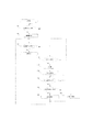
次に図6のフローチャートを用いて、本実施形態における撮像装置の動作を説明する。先ず、ステップS101にて操作部116に含まれる動画撮影スイッチが押下されるまで待機する。動画撮影スイッチが押下されると、ステップS102にて動画撮影が開始される。動画撮影が開始されると第2の撮像素子103、AFE104、TG105に電源が投入され、CPU124は動画撮影設定をする。設定後、CPU124から出力される同期信号に基づいてTG105は撮像素子103に読出しパルスを出力し、撮像素子103は所定のフレームレートでの読出し動作を開始する。なお、本実施形態では動画像の電荷蓄積・読出し動作はスリットローリング動作による電子シャッタ機能を使用して行われるが、この限りではない。撮像素子103から出力されたA像用光電変換部データとB像用光電変換部データは、CPU124によりRAM118へ転送される。その後、画像処理部121に転送され、同一のマイクロレンズ下にあるA像用光電変換部とB像用光電変換部のデータを画素毎に加算する。これにより動画のフレームを作成する。その後、補正処理、圧縮等を行い、表示部117に動画を表示する(ライブビュー)。撮影前に、表示部117に表示されたメニューと操作部116を使用して動画記録が選択されている場合には、動画はフラッシュメモリ123に順次記録される。
Next, the operation of the imaging apparatus in the present embodiment will be described using the flowchart of FIG. First, it waits until the moving image photographing switch included in the
ステップS103では、動画撮影スイッチが再度押下されたかを判断する。動画撮影スイッチが押下されていない場合には動画撮影を継続し、ステップS104の処理を行う。動画撮影スイッチが押下された場合には、動画撮影を終了する。 In step S103, it is determined whether the moving image shooting switch has been pressed again. If the movie shooting switch has not been pressed, movie shooting is continued, and the process of step S104 is performed. When the movie shooting switch is pressed, movie shooting is terminated.
次にステップS104では操作部116に含まれるAFスイッチが押下されたかを判断する。ここでAFスイッチが押下されている場合には、ステップS105にてAF演算を行う。ステップS105では、CPU124はRAM118に格納されるA像用光電変換部データを用いたA像に対応するA画像データと、B像用光電変換部データを用いたB像に対応するB画像データをAF演算部122に転送する。
In step S104, it is determined whether an AF switch included in the
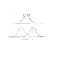
図7(a)は、ピントがあった図5(a)の場合におけるA画像データとB画像データである。横軸は、画素位置を表し、縦軸は出力を表す。ピントがあっている場合はA画像データとB画像データは一致する。図7(b)は、ピントがあっていない図5(b)の場合のA画像データとB画像データである。このときは、A画像データとB画像データは前述した状態によって位相差を持ち、画素位置がずれ量Xでずれている。焦点検出手段であるAF演算部122では、動画フレーム毎のこのずれ量Xを算出することによりピントのずれ量、即ち図5(b)におけるY値を算出する。つまり、焦点検出手段は、第2の撮像素子の焦点検出用画素の出力を用いて、位相差検出方式で焦点検出を行う。AF演算部122は、算出したY値をフォーカス駆動回路112に転送する。
FIG. 7A shows A image data and B image data in the case of FIG. The horizontal axis represents the pixel position, and the vertical axis represents the output. When the image is in focus, the A image data and the B image data match. FIG. 7B shows the A image data and the B image data in the case of FIG. 5B that is not in focus. At this time, the A image data and the B image data have a phase difference depending on the state described above, and the pixel position is shifted by the shift amount X. The
ステップS106では、フォーカス駆動回路112はAF演算部122から取得したY値に基づき第3レンズ群108を動かす量を算出し、フォーカスアクチュエータ114に駆動命令を出力する。第3レンズ群108はフォーカスアクチュエータ114によりピントが合う位置まで移動され、撮像素子103にてピントが合った状態となる。この時、第1の撮像素子100と第2の撮像素子103には、像面倍率が同じである1次結像が入射されており被写界深度等も同一であるため、撮像素子103でピントが合った状態では、撮像素子100でもピントが合った状態となる。
In step S <b> 106, the
次にステップS107にて、操作部116に含まれる静止画撮影スイッチが押下されたかを判断する。静止画撮影スイッチが押下されていた場合にはステップS108にて静止画の撮影が行われる。静止画撮影が開始されると、第1の撮像素子100、AFE101、TG102に電源が投入され、CPU124は静止画撮影設定をする。設定後、CPU124はフォーカルプレーンシャッタ106を操作して撮像素子100に対して露光動作を行う。その後、CPU124から出力される同期信号に基づいてTG102は撮像素子100に読出しパルスを出力し、撮像素子100は読出し動作を開始する。撮像素子100から出力された画像データはAFE101にてデジタルデータに変換された後、RAM118に格納される。CPU124は、RAM118に格納される画像データを画像処理部120に転送し、画像処理部120では画像データの補正処理、圧縮等が行われる。その後、画像データはフラッシュメモリ123に記録される。その後、ステップS103へ戻り、ステップS103からステップS108の動作を繰り返す。
In step S107, it is determined whether the still image shooting switch included in the
ステップS104において、AFスイッチが押下されていない場合は、ステップS107に移行し、静止画撮影スイッチが押下されているか否かを判断する。なお、表示部117と操作部116を使用してメニュー表示からAF動作がOFFに設定されていた場合も、同様である。
If the AF switch is not pressed in step S104, the process proceeds to step S107, and it is determined whether or not the still image shooting switch is pressed. The same applies when the AF operation is set to OFF from the menu display using the
以上の動作により、動画撮影(ライブビューまたは動画記録)を行いながら、位相差AF動作を行って撮像素子103または撮像素子100に入射される像のピントを合わせ、同時に静止画撮影を行うことができる。
With the above operation, while performing moving image shooting (live view or moving image recording), the phase difference AF operation is performed to focus the image incident on the
なお、本実施形態では、第2の撮像素子103は全ての画素が測距可能な画素であり、位相差AFを行う構成にしたが、この限りではない。離散的に配置された測距可能な画素からの信号を使用して位相差AFを行う構成でもよい。この場合の測距可能な画素の構成は、マイクロレンズ下に1つのPDを持ち、遮光層により左または右、或いは上または下を遮光された構成で瞳分割を行う構成でもよい。つまり、第2の撮像素子は、射出瞳の第1の領域を通って瞳分割された光束を受光する第1の光電変換部、又は/及び、射出瞳の第1の領域からずれた第2の領域を通って瞳分割された光束を受光する第2の光電変換部を含む焦点検出用画素を持てばよい。また、撮像素子が、画像用画素と焦点検出用画素を含んで構成されてもよい。
In the present embodiment, the
また、本実施形態では、第2の撮像素子103に測距が可能な画素を含ませ、位相差AFを行う構成にしたが、この限りではない。第2の撮像素子103も、1つのマイクロレンズ下に1つのPDを持つ第1の撮像素子100と同じ画素構成とし、読み出した動画像のコントラストを検出してAF動作を行うコントラストAF方式を適用する構成とすることも可能である。つまり、焦点検出手段は、第2の撮像素子の画素の出力からコントラストを検出し、コントラスト検出方式で焦点検出を行うこともできる。
In the present embodiment, the
加えて、本実施形態では、撮像素子103のA画像データとB画像データは画像処理部で加算されて動画を生成する構成であるが、その限りではない。A画像データ、B画像データがそれぞれ必要ない場合には、一部または全部の画素についてA画像データとB画像データを撮像素子内で加算して出力する構成でもよい。また、本実施形態では動画撮影中に静止画を撮影する動作について述べたが、この限りではない。動画撮影をしていない間に静止画撮影をすることも可能である。
In addition, in the present embodiment, the A image data and B image data of the
(実施形態2)
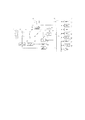
以下、図8を参照して、本発明の第2の実施形態による撮像装置の構成、動作について説明する。図8の撮像装置において、200は、光学像を電気信号に変換する第1の撮像素子である。撮像素子200では主に静止画を撮影する。201は、撮像素子200から出力されたアナログの画像信号に対して、ゲイン調整や所定の量子化ビットに対応してデジタル変換を行うAFEである。202は、撮像素子200及びAFE201の駆動タイミングを制御するTGである。
(Embodiment 2)
Hereinafter, the configuration and operation of the imaging apparatus according to the second embodiment of the present invention will be described with reference to FIG. In the image pickup apparatus of FIG. 8,
203は、光学像を電気信号に変換する第2の撮像素子である。撮像素子203では主に動画を撮影する。204は、撮像素子203から出力されたアナログの画像信号に対して、ゲイン調整や所定の量子化ビットに対応してデジタル変換を行うAFEである。205は、撮像素子203及びAFE204の駆動タイミングを制御するTGである。本実施形態でも、第1の撮像素子200に関連するAFE201、TG202や、第2の撮像素子203に関連するAFE204、TG205が使用されているが、AFE、TGは撮像素子内に内蔵される構成も可能である。
206から224で示される構成要素は、実施形態1の構成要素106から124にそれぞれ対応するものである。相違点は、次の点である。入射された被写体からの光束を反射光と透過光に分割するハーフミラー207の反射光は第1の撮像素子200に入射し、透過光は第2の撮像素子203に入射される。
The components indicated by 206 to 224 correspond to the
図9は撮像素子200、撮像素子203、ハーフミラー207の位置を示した図である。ハーフミラーを通過した像は、ハーフミラーが持つ光学収差により像が不鮮明になりやすい。後述する様に、静止画は、撮像素子203より画素数が多い撮像素子200で撮影されるため、より鮮明な像が要求される。よって、本実施形態では、前述した様にハーフミラー207の反射光は撮像素子200に、透過光は撮像素子203に入射される位置・角度にハーフミラー207が配置される。ハーフミラー207の中心から撮像素子200までの距離cと、撮像素子203までの距離dは等しく配置される。これにより、撮像素子200と撮像素子203には等しい倍率の被写体像である一次結像が入射される。この構成により、後述する撮像素子203の画像信号を用いてAF動作を行った場合でも、撮像素子200に結像する像の焦点を合わせることができる。
FIG. 9 is a diagram illustrating the positions of the
第1の撮像素子200、第2の撮像素子203の構成・機能については実施形態1で述べた構成・機能と同様のため、説明を省略する。なお本実施形態での撮像装置の構成では、撮像素子200は静止画を撮影し、撮像素子203は動画を撮影するため、撮像素子200の画素数h1*i1画素は撮像素子203の画素数h2*i2画素より大きい構成となっている。撮像素子203は撮像素子200よりも画素数が少ないため、PDの面積が大きくなるので感度が高い。ハーフミラー207により分割される光束は透過光と反射光でM:Nの割合で分割され、感度が高い撮像素子203に入射される透過光の割合Mの方がNより小さくなる構成とする。
The configurations and functions of the
次に図10のフローチャートを用いて、本実施形態における撮像装置の動作を説明する。先ず、ステップS201にて操作部116に含まれる動画撮影スイッチが押下されるまで待機する。動画撮影スイッチが押下されると、ステップS202にて動画撮影が開始される。動画撮影が開始されると撮像素子203、AFE204、TG205に電源が投入され、CPU224は動画撮影設定をする。設定後、CPU224から出力される同期信号に基づいてTG205は撮像素子203に読出しパルスを出力し、撮像素子203は所定のフレームレートでの読出し動作を開始する。なお、本実施形態でも、動画像の電荷蓄積・読出し動作はスリットローリング動作による電子シャッタ機能を使用して行われるが、この限りではない。
Next, the operation of the imaging apparatus in the present embodiment will be described using the flowchart of FIG. First, it waits until the moving image photographing switch included in the
撮像素子203から出力されたA像用光電変換部データとB像用光電変換部データは、CPU224によりRAM218へ転送される。その後、画像処理部221に転送され、同一のマイクロレンズ下にあるA像用光電変換部とB像用光電変換部のデータを画素毎に加算する。これにより動画のフレームを作成する。その後、補正処理、圧縮等を行い、表示部217に動画を表示する(ライブビュー)。撮影前に、表示部217に表示されたメニューと操作部216を使用して動画記録が選択されている場合には、動画はフラッシュメモリ223に順次記録される。
The A image photoelectric conversion unit data and the B image photoelectric conversion unit data output from the
ステップS203では、動画撮影スイッチが再度押下されたかを判断する。動画撮影スイッチが押下されていない場合には動画撮影を継続し、ステップS204の処理を行う。動画撮影スイッチが押下された場合には、動画撮影を終了する。ステップS204ではAF演算を行う。CPU224は、RAM218に格納されるA像用光電変換部データを用いたA像に対応するA画像データと、B像用光電変換部データを用いたB像に対応するB画像データをAF演算部222に転送する。図7(a)は、ピントがあった図5(a)の場合におけるA画像データとB画像データである。横軸は、画素位置を表し、縦軸は出力を表す。ピントがあっている場合はA画像データとB画像データは一致する。図7(b)は、ピントがあっていない図5(b)の場合のA画像データとB画像データである。このときは、A画像データとB画像データは前述した状態によって位相差を持ち、画素位置がずれ量Xでずれている。AF演算部222では、動画フレーム毎のこのずれ量Xを算出することによりピントのずれ量、即ち図5(b)におけるY値を算出する。AF演算部222は算出したY値をフォーカス駆動回路212に転送する。ステップS205では、フォーカス駆動回路212はAF演算部222から取得したY値に基づき第3レンズ群208を動かす量を算出し、フォーカスアクチュエータ214に駆動命令を出力する。第3レンズ群208はフォーカスアクチュエータ214によりピントが合う位置まで移動され、撮像素子203にてピントが合った状態となる。この時、撮像素子200と撮像素子203は像面倍率が同じである1次結像が入射されており被写界深度等も同一であるため、撮像素子203でピントが合った状態では、撮像素子200でもピントが合った状態となる。
In step S203, it is determined whether the moving image shooting switch has been pressed again. If the movie shooting switch has not been pressed, movie shooting is continued, and the process of step S204 is performed. When the movie shooting switch is pressed, movie shooting is terminated. In step S204, AF calculation is performed. The
次にステップS206にて、操作部216に含まれる静止画撮影スイッチが押下されたかを判断する。静止画撮影スイッチが押下されていた場合にはステップS207の処理に移行する。ステップS207ではフォーカス駆動、即ち第3レンズ群208の移動が停止したか否かを判断する。停止していない場合には停止するまで待つ。停止した場合には静止画の撮影が行われる。ステップS208にて静止画撮影が開始されると撮像素子200、AFE201、TG202に電源が投入され、CPU224は静止画撮影設定をする。設定後、CPU224はフォーカルプレーンシャッタ206を操作して撮像素子200に対して露光動作を行う。その後、CPU224から出力される同期信号に基づいてTG202は撮像素子200に読出しパルスを出力し、撮像素子200は読出し動作を開始する。撮像素子200から出力された画像データはAFE201にてデジタルデータに変換された後、RAM218に格納される。CPU224はRAM218に格納される画像データを画像処理部220に転送し、画像処理部220では画像データの補正処理、圧縮等が行われる。その後、画像データはフラッシュメモリ223に記録される。その後、ステップS203へ戻り、ステップS203からステップS208の動作を繰り返す。
In step S206, it is determined whether a still image shooting switch included in the
以上の動作の概要を図11に示す。時刻t1からt2の間は動画の1フレームの動作として、A画像データ、B画像データを出力する。時刻t1〜t2で取得したA画像データ、B画像データから前述したAF演算を行い、時刻t2にてフォーカス駆動(第3レンズ群208の移動)を行う。フォーカス駆動は時刻t3にて終了する。動画撮影時は時刻t1からt3の動作を繰り返し、AF動作を常時行う。時刻t4にて静止画撮影スイッチが押下されるが、時刻t4ではフォーカス駆動をしているために静止画撮影は開始されない。時刻t5にてフォーカス駆動が終了した後に、時刻t6に静止画撮影のための同期信号が出力されて静止画撮影が開始される。時刻t7にてフォーカルプレーンシャッタ206が先幕、後幕の順で走行し、撮像素子200の露光を行う。その後t8に撮像素子200から画像データが出力され、前述した処理の後に静止画としてフラッシュメモリ223に記録される。この様にフォーカス駆動が終了してから静止画を撮影する構成により、フォーカス駆動中のピントが合っていない画像を撮影することを避けることができ、鮮明な静止画を得ることができる。
An outline of the above operation is shown in FIG. Between time t1 and t2, A image data and B image data are output as an operation of one frame of the moving image. The AF calculation described above is performed from the A image data and B image data acquired at times t1 and t2, and focus driving (movement of the third lens group 208) is performed at time t2. Focus drive ends at time t3. During moving image shooting, the operation from time t1 to t3 is repeated, and the AF operation is always performed. The still image shooting switch is pressed at time t4, but still image shooting is not started at time t4 because the focus is driven. After the focus drive ends at time t5, a synchronization signal for still image shooting is output at time t6 and still image shooting is started. At time t7, the
以上の動作により、動画撮影(ライブビューまたは動画記録)を行いながら、位相差AF動作を行って撮像素子203または撮像素子200に入射される像のピントを合わせ、同時に静止画撮影を行うことができる。なお、本実施形態でも、実施形態1のところで述べた様な変更が可能である。
With the above operation, while performing moving image shooting (live view or moving image recording), the phase difference AF operation is performed to focus the image incident on the
(実施形態3)
以下、図12を参照して、本発明の第3の実施形態による撮像装置の構成、動作について説明する。図12に示す本実施形態の撮像装置の構成は、実施形態1の撮像装置の構成と同様であり、説明を省略する。つまり、300から324で示される構成要素は、実施形態1の構成要素100から124にそれぞれ対応するものである。また、撮像素子300、撮像素子303、ハーフミラーの位置関係も実施形態1と同様である。
(Embodiment 3)
Hereinafter, the configuration and operation of the imaging apparatus according to the third embodiment of the present invention will be described with reference to FIG. The configuration of the imaging apparatus according to the present embodiment illustrated in FIG. That is, the constituent elements indicated by 300 to 324 correspond to the
本実施形態の第1の撮像素子300について説明する。撮像素子300の構成は、実施形態1の撮像素子100の構成とは画素アレイ部について異なる。撮像素子300の画素アレイ部を図13(a)に示す。図13(a)において、300aはマイクロレンズであり、300c、300bはPDである。各画素、PD2つに対して1つのマイクロレンズが上部に配置される構成となっている。マイクロレンズ300aが共有されている領域を1画素とした場合、この画素が水平方向にj1画素、垂直方向にk1画素並んで配置される。PD300bとPD300cで蓄積された信号は、読出し動作によって別々に外部に出力される。PD300bとPD300cには、位相差を持った別の像が入射されるため、ここではPD300bをA像用光電変換部、PD300cをB像用光電変換部とする。なお、本実施形態でも、マイクロレンズ1つに対してPDが2つ配置される構成であるがこの限りではない。マイクロレンズ1つに対してPDが上下または左右に複数配置される構成であれば適用することができる。以上の様に、本実施形態では、第1の撮像素子も焦点検出用画素を持つ。
The
本実施形態では、撮像素子300から出力されるA像用光電変換部データを用いたA像に対応するA画像データと、B像用光電変換部データを用いたB像に対応するB画像データは以下の様に使用される。A画像データとB画像データは、実施形態1で説明した様にピントが合っていない時には、ピントのずれに応じた位相差のある画像データが得られる。図15(a)、(b)は同一被写体を撮影した場合の画像であり、図15(a)はA画像データ、図15(b)はB画像データである。図15(a)、(b)は人物にピントが合っている時のデータであり、背景がずれている(位相差を持っている)ことが分かる。即ち、A画像データとB画像データの位相差は被写体との距離に依存する。よって、A画像データとB画像データの位相差は所謂視差に置き換えられ、A画像データとB画像データをそれぞれ左右の目に独立に入射する様に表示すると、立体感を持った画像と認識することができる。
In the present embodiment, the A image data corresponding to the A image using the A image photoelectric conversion unit data output from the
本実施形態の撮像装置は、A画像データとB画像データを独立にし、3次元画像として表示することができる形式で記録する3D静止画撮影モードを有する。 The imaging apparatus of the present embodiment has a 3D still image shooting mode in which A image data and B image data are made independent and recorded in a format that can be displayed as a three-dimensional image.
次に第2の撮像素子303について説明する。撮像素子303の構成は、実施形態1の第2の撮像素子103と同様である。撮像素子303の画素アレイを図13(b)に示す。図13(b)において、303aはマイクロレンズであり、303b、303cはPDである。各画素、PD2つに対して1つのマイクロレンズが上部に配置される構成となっている。マイクロレンズ303aが共有されている領域を1画素とした場合、この画素が水平方向にj2画素、垂直方向にk2画素並んで配置される。PD303bとPD303cで蓄積された信号は、読出し動作によって別々に外部に出力される。PD303bとPD303cには、位相差を持った別の像が入射されるため、ここではPD303gをA像用光電変換部、PD303hをB像用光電変換部とする。なお、本実施形態でもマイクロレンズ1つに対してPDが2つ配置される構成であるがこの限りではない。
Next, the
次に図14のフローチャートを用いて、本実施形態における撮像装置の動作を説明する。図14のステップS301〜S307の動作は、実施形態1で述べたステップS101〜S107の動作と同様であるため説明を省略する。ステップS308では、3D静止画撮影モードがONであるか否かを判断する。撮影前に、表示部317に表示されたメニューと操作部316を使用して3D静止画撮影モードがONにされている場合には、ステップS309にて3D静止画の撮影が行われる。3D静止画撮影が開始されると、撮像素子300、AFE301、TG302に電源が投入され、CPU324は静止画撮影設定をする。設定後、CPU324は、フォーカルプレーンシャッタ306を操作して撮像素子300に対して露光動作を行う。その後、CPU324から出力される同期信号に基づいてTG302は撮像素子300に読出しパルスを出力し、撮像素子300は読出し動作を開始する。
Next, the operation of the imaging apparatus according to the present embodiment will be described using the flowchart of FIG. The operations in steps S301 to S307 in FIG. 14 are the same as the operations in steps S101 to S107 described in the first embodiment, and thus description thereof is omitted. In step S308, it is determined whether or not the 3D still image shooting mode is ON. If the 3D still image shooting mode is turned on using the menu displayed on the
読出し動作により、撮像素子300からA画像データとB画像データが出力される。これらはAFE301にてデジタルデータに変換された後、それぞれRAM318に格納される。CPU324は、RAM318に格納されるA画像データとB画像データを画像処理部320に転送し、画像処理部320ではそれぞれ補正処理、圧縮等が行われる。その後A画像データとB画像データはそれぞれ所定のファイル形式でフラッシュメモリ323に記録される。
By the reading operation, A image data and B image data are output from the
ステップS308で、3D静止画撮影モードがOFFである場合には、ステップS310にて通常の静止画撮影が行われる。通常静止画撮影が開始されると、撮像素子300、AFE301、TG302に電源が投入され、CPU324は静止画撮影設定をする。設定後、CPU324は、フォーカルプレーンシャッタ306を操作して撮像素子300に対して露光動作を行う。その後、CPU324から出力される同期信号に基づいてTG302は撮像素子300に読出しパルスを出力し、撮像素子300は読出し動作を開始する。読出し動作により、撮像素子300からA画像データとB画像データが出力される。これらはAFE301にてデジタルデータに変換された後、それぞれRAM318に格納される。CPU324は、RAM318に格納されるA画像データとB画像データを画像処理部320に転送され、同一のマイクロレンズ下にあるA像用光電変換部とB像用光電変換部のデータを画素毎に加算する。これにより通常静止画を生成する。その後、補正処理、圧縮等が行われ、通常静止画はフラッシュメモリ323に記録される。その後ステップS303へ戻り、ステップS303からステップS310の動作を繰り返す。
If the 3D still image shooting mode is OFF in step S308, normal still image shooting is performed in step S310. When normal still image shooting is started, the
以上の動作により、動画撮影(ライブビューまたは動画記録)を行いながら、位相差AF動作を行って撮像素子303または撮像素子300に入射される像のピントを合わせ、同時に3次元表示が可能な静止画撮影を行うことができる。
With the above operation, while performing moving image shooting (live view or moving image recording), the phase difference AF operation is performed to focus the image incident on the
なお、本実施形態では撮像素子303で動画、撮像素子300で3次元の静止画を撮影する構成であったがこの限りではない。撮像素子300による動画は、3次元表示が可能な動画を撮影する構成でもよい。また、撮像素子300と撮像素子303の両方の画素信号からAF動作を行う構成でもよい。例えば、撮像素子300は左右に並んだA像用光電変換部、B像用光電変換部を持ち、撮像素子303は上下に並んだA像用光電変換部、B像用光電変換部を持つ構成で、それぞれ左右方向と上下方向の位相差を検出する方法でもよい。さらに、本実施形態でも、実施形態1のところで述べた様な変更が可能である。
In the present embodiment, the moving image is picked up by the
以上、本発明の実施形態について説明したが、本発明はこれらの実施形態に限定されず、その要旨の範囲内で種々の変形及び変更が可能である。 As mentioned above, although embodiment of this invention was described, this invention is not limited to these embodiment, A various deformation | transformation and change are possible within the range of the summary.
100・・第1の撮像素子、103・・第2の撮像素子、107・・ハーフミラー(光分割手段)、112・・フォーカス駆動回路(焦点位置変更手段)120、121・・画像処理部(画像処理手段)、122・・AF演算部(焦点検出手段)
100...
Claims (10)
光電変換部を含む画素が2次元に配置されている第2の撮像素子と、
共通光学系に入射された光束を前記第1の撮像素子と前記第2の撮像素子にそれぞれ入射させる光分割手段と、
前記第2の撮像素子の画素からの信号に基づいて焦点検出を行う焦点検出手段と、
前記焦点検出手段の検出結果に基づいて前記共通光学系の焦点位置を変更する焦点位置変更手段と、
前記第1の撮像素子の画素からの信号と前記第2の撮像素子の画素からの信号を処理する画像処理手段と、
を備え、
前記第2の撮像素子は、前記共通光学系の射出瞳の第1の領域を通って瞳分割された光束を受光するための第1の光電変換部、又は/及び、前記共通光学系の射出瞳の第1の領域からずれた第2の領域を通って瞳分割された光束を受光するための第2の光電変換部を含む焦点検出用画素を持ち、
前記第1の撮像素子と前記第2の撮像素子に前記共通光学系で像が結像される様に、前記第1の撮像素子と前記第2の撮像素子と前記光分割手段が配置され、
前記第1の撮像素子の画素からの信号と前記第2の撮像素子の画素からの信号が、それぞれ、前記画像処理手段で独立に処理されることを特徴とする撮像装置。 A first imaging element in which pixels including a photoelectric conversion unit are two-dimensionally arranged;
A second imaging element in which pixels including a photoelectric conversion unit are two-dimensionally arranged;
Light splitting means for causing the light beam incident on the common optical system to enter the first image sensor and the second image sensor, respectively;
Focus detection means for performing focus detection based on a signal from a pixel of the second image sensor;
A focus position changing means for changing a focus position of the common optical system based on a detection result of the focus detecting means;
Image processing means for processing signals from the pixels of the first image sensor and signals from the pixels of the second image sensor;
With
The second image sensor includes a first photoelectric conversion unit for receiving a light beam divided through the first region of the exit pupil of the common optical system, and / or the exit of the common optical system. Having a focus detection pixel including a second photoelectric conversion unit for receiving a light beam divided into pupils through a second region shifted from the first region of the pupil;
The first image sensor, the second image sensor, and the light dividing means are arranged so that an image is formed on the first image sensor and the second image sensor by the common optical system.
An image pickup apparatus, wherein a signal from a pixel of the first image sensor and a signal from a pixel of the second image sensor are each independently processed by the image processing means.
前記第2の撮像素子の前記焦点検出用画素の出力を用いて、位相差検出方式で焦点検出を行うことを特徴とする請求項1から3の何れか1項に記載の撮像装置。 The focus detection means includes
4. The imaging apparatus according to claim 1, wherein focus detection is performed by a phase difference detection method using an output of the focus detection pixel of the second imaging element. 5.
前記第2の撮像素子の画素の出力からコントラストを検出し、コントラスト検出方式で焦点検出を行うことを特徴とする請求項1から3の何れか1項に記載の撮像装置。 The focus detection means includes
4. The image pickup apparatus according to claim 1, wherein contrast is detected from an output of a pixel of the second image pickup element, and focus detection is performed by a contrast detection method. 5.
前記第2の撮像素子は、前記光分割手段の反射光が入射されることを特徴とする請求項1から5の何れか1項に記載の撮像装置。 The first imaging element receives light transmitted through the light splitting unit,
6. The imaging apparatus according to claim 1, wherein reflected light of the light splitting unit is incident on the second imaging element. 7.
前記第2の撮像素子は、前記光分割手段の透過光が入射されることを特徴とする請求項1から5の何れか1項に記載の撮像装置。 The first imaging element receives the reflected light of the light splitting means,
The imaging apparatus according to claim 1, wherein the second imaging element receives light transmitted through the light splitting unit.
前記第2の撮像素子は、主に動画を撮影する機能を有することを特徴とする請求項1から8の何れか1項に記載の撮像装置。 The first image sensor mainly has a function of photographing a still image,
The image pickup apparatus according to claim 1, wherein the second image pickup element mainly has a function of taking a moving image.
Priority Applications (7)
| Application Number | Priority Date | Filing Date | Title |
|---|---|---|---|
| JP2012277813A JP2014122957A (en) | 2012-12-20 | 2012-12-20 | Imaging device |
| US14/107,649 US9473688B2 (en) | 2012-12-20 | 2013-12-16 | Image pickup apparatus comprising a plurality of imaging sensors and image processing units |
| GB1322499.3A GB2511183B (en) | 2012-12-20 | 2013-12-19 | Image pickup apparatus |
| DE102013226588.3A DE102013226588B4 (en) | 2012-12-20 | 2013-12-19 | RECORDING DEVICE |
| CN201710340139.4A CN107181898A (en) | 2012-12-20 | 2013-12-20 | Picture pick-up device |
| CN201310713586.1A CN103888666B (en) | 2012-12-20 | 2013-12-20 | Picture pick-up device |
| US15/235,381 US9848119B2 (en) | 2012-12-20 | 2016-08-12 | Image pickup apparatus comprising image sensors and a light beam splitter |
Applications Claiming Priority (1)
| Application Number | Priority Date | Filing Date | Title |
|---|---|---|---|
| JP2012277813A JP2014122957A (en) | 2012-12-20 | 2012-12-20 | Imaging device |
Publications (2)
| Publication Number | Publication Date |
|---|---|
| JP2014122957A true JP2014122957A (en) | 2014-07-03 |
| JP2014122957A5 JP2014122957A5 (en) | 2016-02-18 |
Family
ID=51403504
Family Applications (1)
| Application Number | Title | Priority Date | Filing Date |
|---|---|---|---|
| JP2012277813A Pending JP2014122957A (en) | 2012-12-20 | 2012-12-20 | Imaging device |
Country Status (1)
| Country | Link |
|---|---|
| JP (1) | JP2014122957A (en) |
Cited By (6)
| Publication number | Priority date | Publication date | Assignee | Title |
|---|---|---|---|---|
| JP2016058814A (en) * | 2014-09-08 | 2016-04-21 | キヤノン株式会社 | Image recording apparatus, method, and program |
| US20160349522A1 (en) * | 2015-05-29 | 2016-12-01 | Canon Kabushiki Kaisha | Imaging apparatus with two image sensors |
| JP2017069896A (en) * | 2015-10-02 | 2017-04-06 | 京セラ株式会社 | Electronic device |
| CN108566524A (en) * | 2018-01-31 | 2018-09-21 | 深圳市光微科技有限公司 | Pixel unit, image sensor chip, imaging system, the forming method of pixel unit and depth information measuring method |
| WO2019244781A1 (en) | 2018-06-18 | 2019-12-26 | Canon Kabushiki Kaisha | Image capture apparatus and control method thereof |
| US10880477B2 (en) | 2018-04-26 | 2020-12-29 | Canon Kabushiki Kaisha | Image capturing apparatus and multi-readout mode control method for carrying out a live view display |
Citations (11)
| Publication number | Priority date | Publication date | Assignee | Title |
|---|---|---|---|---|
| JPS5824105A (en) * | 1981-07-13 | 1983-02-14 | ハネウエル・インコ−ポレ−テツド | Video detection array |
| JPH04345279A (en) * | 1991-05-22 | 1992-12-01 | Konica Corp | Automatic focusing device for still video camera |
| JPH08251466A (en) * | 1995-03-10 | 1996-09-27 | Canon Inc | Automatic focusing device for composite camera |
| JP2000224458A (en) * | 1999-02-04 | 2000-08-11 | Olympus Optical Co Ltd | Electronic camera |
| JP2007065330A (en) * | 2005-08-31 | 2007-03-15 | Canon Inc | Camera |
| JP2007072254A (en) * | 2005-09-08 | 2007-03-22 | Casio Comput Co Ltd | Imaging apparatus and its program |
| JP2007097033A (en) * | 2005-09-30 | 2007-04-12 | Casio Comput Co Ltd | Imaging apparatus and program therefor |
| JP2008177903A (en) * | 2007-01-19 | 2008-07-31 | Nikon Corp | Imaging device |
| JP2008211631A (en) * | 2007-02-27 | 2008-09-11 | Nikon Corp | Focal point detection element, focal point detector, and imaging apparatus |
| JP2012043939A (en) * | 2010-08-18 | 2012-03-01 | Sony Corp | Imaging element and imaging apparatus |
| JP2012182332A (en) * | 2011-03-02 | 2012-09-20 | Sony Corp | Imaging element and imaging device |
-
2012
- 2012-12-20 JP JP2012277813A patent/JP2014122957A/en active Pending
Patent Citations (11)
| Publication number | Priority date | Publication date | Assignee | Title |
|---|---|---|---|---|
| JPS5824105A (en) * | 1981-07-13 | 1983-02-14 | ハネウエル・インコ−ポレ−テツド | Video detection array |
| JPH04345279A (en) * | 1991-05-22 | 1992-12-01 | Konica Corp | Automatic focusing device for still video camera |
| JPH08251466A (en) * | 1995-03-10 | 1996-09-27 | Canon Inc | Automatic focusing device for composite camera |
| JP2000224458A (en) * | 1999-02-04 | 2000-08-11 | Olympus Optical Co Ltd | Electronic camera |
| JP2007065330A (en) * | 2005-08-31 | 2007-03-15 | Canon Inc | Camera |
| JP2007072254A (en) * | 2005-09-08 | 2007-03-22 | Casio Comput Co Ltd | Imaging apparatus and its program |
| JP2007097033A (en) * | 2005-09-30 | 2007-04-12 | Casio Comput Co Ltd | Imaging apparatus and program therefor |
| JP2008177903A (en) * | 2007-01-19 | 2008-07-31 | Nikon Corp | Imaging device |
| JP2008211631A (en) * | 2007-02-27 | 2008-09-11 | Nikon Corp | Focal point detection element, focal point detector, and imaging apparatus |
| JP2012043939A (en) * | 2010-08-18 | 2012-03-01 | Sony Corp | Imaging element and imaging apparatus |
| JP2012182332A (en) * | 2011-03-02 | 2012-09-20 | Sony Corp | Imaging element and imaging device |
Cited By (11)
| Publication number | Priority date | Publication date | Assignee | Title |
|---|---|---|---|---|
| JP2016058814A (en) * | 2014-09-08 | 2016-04-21 | キヤノン株式会社 | Image recording apparatus, method, and program |
| US20160349522A1 (en) * | 2015-05-29 | 2016-12-01 | Canon Kabushiki Kaisha | Imaging apparatus with two image sensors |
| US9854146B2 (en) * | 2015-05-29 | 2017-12-26 | Canon Kabushiki Kaisha | Imaging apparatus with two image sensors |
| JP2017069896A (en) * | 2015-10-02 | 2017-04-06 | 京セラ株式会社 | Electronic device |
| US10063769B2 (en) | 2015-10-02 | 2018-08-28 | Kyocera Corporation | Electronic apparatus |
| CN108566524A (en) * | 2018-01-31 | 2018-09-21 | 深圳市光微科技有限公司 | Pixel unit, image sensor chip, imaging system, the forming method of pixel unit and depth information measuring method |
| CN108566524B (en) * | 2018-01-31 | 2023-10-27 | 光微信息科技(合肥)有限公司 | Pixel unit, image sensor chip, imaging system, pixel unit forming method and depth information measuring and calculating method |
| US10880477B2 (en) | 2018-04-26 | 2020-12-29 | Canon Kabushiki Kaisha | Image capturing apparatus and multi-readout mode control method for carrying out a live view display |
| WO2019244781A1 (en) | 2018-06-18 | 2019-12-26 | Canon Kabushiki Kaisha | Image capture apparatus and control method thereof |
| US11381763B2 (en) | 2018-06-18 | 2022-07-05 | Canon Kabushiki Kaisha | Image capture apparatus and control method thereof |
| US11736824B2 (en) | 2018-06-18 | 2023-08-22 | Canon Kabushiki Kaisha | Image capture apparatus and control method thereof |
Similar Documents
| Publication | Publication Date | Title |
|---|---|---|
| US9848119B2 (en) | Image pickup apparatus comprising image sensors and a light beam splitter | |
| JP2013145314A (en) | Image processing apparatus, imaging apparatus, control method and program | |
| JP2014122957A (en) | Imaging device | |
| US9967451B2 (en) | Imaging apparatus and imaging method that determine whether an object exists in a refocusable range on the basis of distance information and pupil division of photoelectric converters | |
| JP6249636B2 (en) | Imaging apparatus and control method thereof | |
| JP2013218297A (en) | Focus adjustment device and focus adjustment method | |
| JP5886781B2 (en) | FOCUS DETECTION DEVICE, FOCUS DETECTION METHOD AND PROGRAM, AND IMAGING DEVICE | |
| RU2567438C1 (en) | Image forming device and method of controlling same | |
| JP6334847B2 (en) | FOCUS DETECTION DEVICE, FOCUS DETECTION METHOD AND PROGRAM, AND IMAGING DEVICE | |
| JP5627438B2 (en) | IMAGING DEVICE, ITS CONTROL METHOD, PROGRAM, AND STORAGE MEDIUM | |
| US10122913B2 (en) | Image capturing apparatus and control method thereof, and storage medium | |
| JP2020014195A (en) | Imaging device | |
| JP6004741B2 (en) | Image processing apparatus, control method therefor, and imaging apparatus | |
| JP6700751B2 (en) | IMAGING DEVICE, IMAGING DEVICE CONTROL METHOD, AND PROGRAM | |
| JP6444254B2 (en) | FOCUS DETECTION DEVICE, IMAGING DEVICE, FOCUS DETECTION METHOD, PROGRAM, AND STORAGE MEDIUM | |
| JP6566800B2 (en) | Imaging apparatus and imaging method | |
| US10904424B2 (en) | Image capturing apparatus | |
| JP2018010213A (en) | Control apparatus, imaging apparatus, control method, program, and storage medium | |
| JP2013118514A (en) | Imaging apparatus and method for controlling imaging apparatus | |
| JP2019041300A (en) | Imaging apparatus | |
| JP6234097B2 (en) | Imaging apparatus and control method thereof | |
| JP2021152600A (en) | Imaging apparatus and method for controlling the same, program, and storage medium | |
| JP2014222268A (en) | Imaging device and imaging device control method | |
| JP2018014654A (en) | Imaging apparatus | |
| JP2018128678A (en) | Imaging apparatus |
Legal Events
| Date | Code | Title | Description |
|---|---|---|---|
| A521 | Request for written amendment filed |
Free format text: JAPANESE INTERMEDIATE CODE: A523 Effective date: 20151221 |
|
| A621 | Written request for application examination |
Free format text: JAPANESE INTERMEDIATE CODE: A621 Effective date: 20151221 |
|
| A977 | Report on retrieval |
Free format text: JAPANESE INTERMEDIATE CODE: A971007 Effective date: 20160812 |
|
| A131 | Notification of reasons for refusal |
Free format text: JAPANESE INTERMEDIATE CODE: A131 Effective date: 20160830 |
|
| A521 | Request for written amendment filed |
Free format text: JAPANESE INTERMEDIATE CODE: A523 Effective date: 20161028 |
|
| A131 | Notification of reasons for refusal |
Free format text: JAPANESE INTERMEDIATE CODE: A131 Effective date: 20170404 |
|
| A521 | Request for written amendment filed |
Free format text: JAPANESE INTERMEDIATE CODE: A523 Effective date: 20170601 |
|
| A02 | Decision of refusal |
Free format text: JAPANESE INTERMEDIATE CODE: A02 Effective date: 20171130 |