JP2014122877A - Gas sensor - Google Patents
Gas sensor Download PDFInfo
- Publication number
- JP2014122877A JP2014122877A JP2013198541A JP2013198541A JP2014122877A JP 2014122877 A JP2014122877 A JP 2014122877A JP 2013198541 A JP2013198541 A JP 2013198541A JP 2013198541 A JP2013198541 A JP 2013198541A JP 2014122877 A JP2014122877 A JP 2014122877A
- Authority
- JP
- Japan
- Prior art keywords
- gas
- cover
- axial
- measured
- sensor element
- Prior art date
- Legal status (The legal status is an assumption and is not a legal conclusion. Google has not performed a legal analysis and makes no representation as to the accuracy of the status listed.)
- Granted
Links
Images


Classifications
-
- G—PHYSICS
- G01—MEASURING; TESTING
- G01N—INVESTIGATING OR ANALYSING MATERIALS BY DETERMINING THEIR CHEMICAL OR PHYSICAL PROPERTIES
- G01N27/00—Investigating or analysing materials by the use of electric, electrochemical, or magnetic means
- G01N27/26—Investigating or analysing materials by the use of electric, electrochemical, or magnetic means by investigating electrochemical variables; by using electrolysis or electrophoresis
- G01N27/403—Cells and electrode assemblies
- G01N27/406—Cells and probes with solid electrolytes
- G01N27/407—Cells and probes with solid electrolytes for investigating or analysing gases
- G01N27/4077—Means for protecting the electrolyte or the electrodes
-
- G—PHYSICS
- G01—MEASURING; TESTING
- G01M—TESTING STATIC OR DYNAMIC BALANCE OF MACHINES OR STRUCTURES; TESTING OF STRUCTURES OR APPARATUS, NOT OTHERWISE PROVIDED FOR
- G01M15/00—Testing of engines
- G01M15/04—Testing internal-combustion engines
- G01M15/10—Testing internal-combustion engines by monitoring exhaust gases or combustion flame
- G01M15/102—Testing internal-combustion engines by monitoring exhaust gases or combustion flame by monitoring exhaust gases
-
- G—PHYSICS
- G01—MEASURING; TESTING
- G01N—INVESTIGATING OR ANALYSING MATERIALS BY DETERMINING THEIR CHEMICAL OR PHYSICAL PROPERTIES
- G01N33/00—Investigating or analysing materials by specific methods not covered by groups G01N1/00 - G01N31/00
- G01N33/0004—Gaseous mixtures, e.g. polluted air
- G01N33/0009—General constructional details of gas analysers, e.g. portable test equipment
Abstract
Description
本発明は、被測定ガス中の特定ガス濃度を検出するためのガスセンサに関する。 The present invention relates to a gas sensor for detecting a specific gas concentration in a gas to be measured.
従来、自動車の内燃機関の排気管等に設けられ、被測定ガスである排ガス中の特定ガス濃度を検出するためのガスセンサが知られている。
ガスセンサとしては、例えば、被測定ガス中の特定ガス濃度を検出するセンサ素子と、センサ素子を内側に挿通して保持するハウジングと、ハウジングの先端側に配設された素子カバーとを備えたものがある。
2. Description of the Related Art Conventionally, a gas sensor that is provided in an exhaust pipe of an internal combustion engine of an automobile and detects a specific gas concentration in exhaust gas that is a gas to be measured is known.
The gas sensor includes, for example, a sensor element that detects a specific gas concentration in the gas to be measured, a housing that is inserted and held inside the sensor element, and an element cover that is disposed on the front end side of the housing. There is.
例えば、特許文献1には、センサ素子の被水防止等のため、ガス導入部が設けられたセンサ素子の先端部を覆うインナカバーと、インナカバーの外側に配設されたアウタカバーとからなる二重構造の素子カバーを備えたガスセンサが開示されている。
このガスセンサにおいて、アウタカバーには、アウタカバー内に被測定ガスを導入するためのアウタ導入開口部が設けられている。また、インナカバーには、インナカバー内に被測定ガスを導入するためのインナ導入開口部が設けられている。
For example, Japanese Patent Laid-Open No. 2004-228561 includes an inner cover that covers a front end portion of a sensor element provided with a gas introduction part and an outer cover that is disposed outside the inner cover in order to prevent the sensor element from being wetted. A gas sensor having a heavy structure element cover is disclosed.
In this gas sensor, the outer cover is provided with an outer introduction opening for introducing the gas to be measured into the outer cover. Further, the inner cover is provided with an inner introduction opening for introducing the gas to be measured into the inner cover.
ところで、多気筒の内燃機関では、気筒間の燃料噴射量のばらつき等により、気筒間において空燃比のばらつき(気筒間インバランス)が生じる。近年、さらなる排ガス規制、燃費規制により、内燃機関の気筒間インバランスをガスセンサにおいてより精度良く検出し、内燃機関の各気筒の空燃比制御を行うことが求められている。したがって、気筒間インバランスの指標となるガスセンサの出力値(空燃比:A/F)の変化をより正確に把握するため、各気筒の空燃比変化に伴うガスセンサの応答性をさらに高めることが必要となる。具体的には、従来のA/F変化に対する応答性とは異なり、特にセンサ素子を保護する素子カバーにおいては、センサ素子のガス検出部(被測定ガスを検出するための部分)により多くの被測定ガスを短距離で迅速に到達させることに加え、センサ素子の検出部に到達するまでの間に、各気筒から順次排気されるA/Fの異なる被測定ガスが混合されにくくすることが不可欠となる。 By the way, in a multi-cylinder internal combustion engine, variations in air-fuel ratio (inter-cylinder imbalance) occur between cylinders due to variations in fuel injection amounts between cylinders and the like. In recent years, due to further exhaust gas regulations and fuel efficiency regulations, it has been required to detect the imbalance between cylinders of an internal combustion engine with a gas sensor more accurately and to control the air-fuel ratio of each cylinder of the internal combustion engine. Therefore, in order to grasp the change of the output value (air / fuel ratio: A / F) of the gas sensor which is an index of the imbalance between cylinders more accurately, it is necessary to further improve the responsiveness of the gas sensor accompanying the change of the air / fuel ratio of each cylinder. It becomes. Specifically, unlike the response to the conventional A / F change, particularly in the element cover that protects the sensor element, the gas detection part of the sensor element (the part for detecting the gas to be measured) has a larger coverage. In addition to making the measurement gas reach quickly in a short distance, it is essential to make it difficult to mix the gases to be measured with different A / F exhausted sequentially from each cylinder before reaching the detection part of the sensor element. It becomes.
しかしながら、上記特許文献1のガスセンサでは、主にセンサ素子の被水を防止することに重点が置かれていたため、内燃機関の気筒間インバランスの検出精度を考えた場合には、気筒間インバランスを検出する応答性が十分でない。この要因としては、インナ導入開口部からインナカバー内に導入された被測定ガスがセンサ素子のガス導入部に到達するまでの距離が長いことなどが考えられる。この距離が長いと、時間的に前後して排気され、センサ素子のガス検出部に前後して到達する被測定ガスが混ざりやすくなってしまう。この被測定ガスの混合が生じると、いずれかの気筒から排気される被測定ガスの空燃比がリッチ側に変動し、他のいずれかの気筒から排気される被測定ガスの空燃比がリーン側に変動していたとしても、これらの被測定ガスが混合された状態の空燃比を検出することになってしまう。その結果、内燃機関の気筒間インバランスの検出精度が低下し、気筒間インバランスを検出するためのガスセンサの応答性が低下するおそれがある。
However, the gas sensor disclosed in
本発明は、かかる背景に鑑みてなされたものであり、内燃機関の気筒間インバランスの検出精度を高めることができ、気筒間インバランスを検出する応答性に優れたガスセンサを提供しようとするものである。 The present invention has been made in view of such a background, and is intended to provide a gas sensor that can improve the accuracy of detecting an imbalance between cylinders of an internal combustion engine and has excellent responsiveness for detecting the imbalance between cylinders. It is.
本発明の一の態様は、被測定ガス中の特定ガス濃度を検出するセンサ素子と、
該センサ素子を内側に挿通して保持するハウジングと、
該ハウジングの軸方向先端側に配設された素子カバーとを備え、
上記センサ素子の先端部には、その内部に被測定ガスを導入するためのガス導入部が設けられており、
上記素子カバーは、上記センサ素子の先端部を覆うように配設されたインナカバーと、該インナカバーの外側に配設されたアウタカバーとを有し、
該アウタカバーには、該アウタカバー内に被測定ガスを導入するためのアウタ導入開口部が設けられており、
上記インナカバーには、該インナカバー内に被測定ガスを導入するためのインナ導入開口部が設けられており、
上記センサ素子の上記ガス導入部の軸方向中間位置は、上記インナカバーの上記インナ導入開口部の軸方向基端位置よりも軸方向基端側にあることを特徴とするガスセンサにある。
One aspect of the present invention is a sensor element for detecting a specific gas concentration in a gas to be measured;
A housing for inserting and holding the sensor element inside,
An element cover disposed on the front end side in the axial direction of the housing,
The tip of the sensor element is provided with a gas introduction part for introducing a gas to be measured therein,
The element cover has an inner cover disposed so as to cover the tip of the sensor element, and an outer cover disposed on the outer side of the inner cover,
The outer cover is provided with an outer introduction opening for introducing a gas to be measured into the outer cover,
The inner cover is provided with an inner introduction opening for introducing a gas to be measured into the inner cover,
The gas sensor is characterized in that the intermediate position in the axial direction of the gas introduction part of the sensor element is closer to the axial base end side than the axial base end position of the inner introduction opening of the inner cover.
上記ガスセンサにおいて、センサ素子の先端部には、その内部に被測定ガスを導入するためのガス導入部が設けられている。また、センサ素子の先端部を覆うインナカバーには、インナカバー内に被測定ガスを導入するためのインナ導入開口部が設けられている。そして、センサ素子のガス導入部の軸方向中間位置は、インナカバーのインナ導入開口部の軸方向基端位置よりも軸方向基端側にある。 In the gas sensor, a gas introduction part for introducing a gas to be measured is provided at the tip of the sensor element. The inner cover that covers the tip of the sensor element is provided with an inner introduction opening for introducing the gas to be measured into the inner cover. And the axial direction intermediate position of the gas introduction part of a sensor element exists in the axial direction base end side rather than the axial base end position of the inner introduction opening part of an inner cover.
すなわち、アウタ導入開口部からアウタカバー内(アウタカバーとインナカバーとの間)に導入された被測定ガスは、インナ導入開口部からインナカバー内に導入され、センサ素子のガス導入部に到達する。
本発明者らは、このような被測定ガスの流れにおいて、インナ導入開口部からインナカバー内に導入された被測定ガスがセンサ素子のガス導入部に到達するまでの距離が、内燃機関の気筒間インバランスの検出精度、及び気筒間インバランスを検出する応答性に大きく寄与することを見出した。
That is, the gas to be measured introduced into the outer cover (between the outer cover and the inner cover) from the outer introduction opening is introduced into the inner cover from the inner introduction opening and reaches the gas introduction part of the sensor element.
In the flow of the gas to be measured, the present inventors have found that the distance from the inner introduction opening to the gas to be measured introduced into the inner cover reaches the gas introduction part of the sensor element is the cylinder of the internal combustion engine. It has been found that it greatly contributes to the detection accuracy of the imbalance between cylinders and the responsiveness to detect the imbalance between cylinders.
そして、本発明者らは、インナ導入開口部からインナカバー内に導入された被測定ガスがセンサ素子のガス導入部に到達するまでの距離を短くするためには、被測定ガスがインナカバー内に導入される部分であるインナ導入開口部の軸方向基端位置を、被測定ガスがセンサ素子の内部に導入される部分であるガス導入部の軸方向中間位置よりも軸方向基端側とすることが非常に有効であることを見出した。 In order to shorten the distance from the inner introduction opening to the gas to be measured introduced into the inner cover until the gas to be measured reaches the gas introduction part of the sensor element, the gas to be measured is contained in the inner cover. The axial base end position of the inner introduction opening, which is a part introduced into the gas sensor, is set to an axial base end side with respect to the axial intermediate position of the gas introduction part, which is a part into which the gas to be measured is introduced into the sensor element. Found it to be very effective.
これにより、インナ導入開口部からインナカバー内に導入された被測定ガスをできるだけ短距離で迅速にセンサ素子のガス導入部に到達させることができる。また、被測定ガスを他のインナ導入開口部から流れ込んだ被測定ガスと混合させることなく、センサ素子のガス導入部に到達させることができる。そして、内燃機関の各気筒の被測定ガスを順にセンサ素子のガス導入部に到達させ、センサ素子のガス導入部に到達するまでの間に各気筒の被測定ガスが混合されることを抑制することができる。 As a result, the gas to be measured introduced into the inner cover from the inner introduction opening can reach the gas introduction portion of the sensor element as quickly as possible. Further, the gas to be measured can reach the gas introduction part of the sensor element without being mixed with the gas to be measured flowing from the other inner introduction opening. Then, the gas to be measured in each cylinder of the internal combustion engine is made to reach the gas introduction part of the sensor element in order, and the gas to be measured in each cylinder is prevented from being mixed before reaching the gas introduction part of the sensor element. be able to.
その結果、ガスセンサの応答性を高めることができ、内燃機関の気筒間インバランスの指標となるガスセンサの出力値(例えば、空燃比:A/F等)の変化をより正確に把握することができる。そして、ガスセンサにおける内燃機関の気筒間インバランスの検出精度を向上させることができる。 As a result, the responsiveness of the gas sensor can be improved, and the change in the output value (for example, air-fuel ratio: A / F) of the gas sensor that is an index of the imbalance between cylinders of the internal combustion engine can be grasped more accurately. . And the detection accuracy of the imbalance between cylinders of the internal combustion engine in a gas sensor can be improved.
このように、内燃機関の気筒間インバランスの検出精度を高めることができ、気筒間インバランスを検出する応答性に優れたガスセンサを提供することができる。 Thus, the detection accuracy of the imbalance between cylinders of the internal combustion engine can be improved, and a gas sensor excellent in responsiveness for detecting the imbalance between cylinders can be provided.
上記ガスセンサにおいて、「軸方向先端側」とは、ガスセンサの軸方向の一方側であり、ガスセンサが被測定ガスに晒される側をいう。また、「軸方向基端側」とは、その反対側をいう。 In the gas sensor, the “axial tip side” is one side in the axial direction of the gas sensor and refers to the side where the gas sensor is exposed to the gas to be measured. Further, “axial direction proximal end side” refers to the opposite side.
また、上記センサ素子としては、例えば、被測定ガス側電極及び基準ガス側電極を設けた酸素イオン伝導性の固体電解質体、被測定ガス側電極に接触させる被測定ガスを透過させる多孔質の拡散抵抗層等を積層して構成された積層型のセンサ素子を用いることができる。上記構成の場合、センサ素子の外表面に拡散抵抗層の一部が露出しており、その露出した部分が上記ガス導入部となる。 The sensor element may be, for example, an oxygen ion conductive solid electrolyte provided with a measured gas side electrode and a reference gas side electrode, or a porous diffusion that allows the measured gas to contact with the measured gas side electrode. A stacked sensor element formed by stacking resistive layers and the like can be used. In the case of the above configuration, a part of the diffusion resistance layer is exposed on the outer surface of the sensor element, and the exposed part becomes the gas introduction part.
また、上記センサ素子の先端部には、上記ガス導入部が複数箇所設けられていてもよい。
また、上記センサ素子の外表面には、少なくとも拡散抵抗層の露出した部分(ガス導入部)を覆うように、被測定ガス中の被毒成分を捕獲するための保護層等が設けられていてもよい。
Further, a plurality of the gas introducing portions may be provided at the tip of the sensor element.
The outer surface of the sensor element is provided with a protective layer or the like for capturing poisonous components in the gas to be measured so as to cover at least the exposed portion (gas introducing portion) of the diffusion resistance layer. Also good.
また、上記アウタカバーには、上記アウタ導入開口部が周方向に並んで複数設けられていてもよい。
また、上記インナカバーには、上記インナ導入開口部が周方向に並んで複数設けられていてもよい。
また、上記インナ導入開口部が複数設けられている場合には、上記センサ素子の上記ガス導入部の軸方向中間位置は、そのすべてのインナ導入開口部の軸方向基端位置よりも軸方向基端側にあることが好ましい。
The outer cover may be provided with a plurality of outer introduction openings arranged in the circumferential direction.
Moreover, the said inner cover may be provided with two or more said inner introduction opening parts along with the circumferential direction.
Further, when a plurality of the inner introduction openings are provided, the axial intermediate position of the gas introduction part of the sensor element is more axially based than the axial base end positions of all of the inner introduction openings. It is preferable that it exists in an end side.
また、上記インナ導入開口部が複数設けられている場合には、そのすべてのインナ導入開口部の軸方向位置が同じであることが好ましい。また、インナ導入開口部からガス導入部までの径方向距離が同じであることが好ましい。
この場合には、インナ導入開口部からセンサ素子のガス導入部までの距離のばらつきを抑制し、内燃機関の気筒間インバランスの検出精度、及び気筒間インバランスを検出する応答性をより一層高めることができる。
Moreover, when the said inner introduction opening part is provided with two or more, it is preferable that the axial direction position of all the inner introduction opening parts is the same. Moreover, it is preferable that the radial direction distance from an inner introduction opening part to a gas introduction part is the same.
In this case, variation in the distance from the inner introduction opening to the gas introduction part of the sensor element is suppressed, and the detection accuracy of the inter-cylinder imbalance of the internal combustion engine and the responsiveness for detecting the imbalance between the cylinders are further improved. be able to.
また、上記インナカバーの上記インナ導入開口部の軸方向基端位置から上記センサ素子の上記ガス導入部の軸方向中間位置までの軸方向距離aは、例えば、0mm<a≦3.0mmとすることが好ましく、さらに0.7mm≦a≦3.0mmとすることがより好ましい。
この場合には、インナ導入開口部からインナカバー内に導入された被測定ガスをより一層短距離で迅速にセンサ素子のガス導入部に到達させることができる。そして、内燃機関の気筒間インバランスの検出精度、及び気筒間インバランスを検出する応答性をさらに高めることができる。
The axial distance a from the axial base end position of the inner introduction opening of the inner cover to the axial middle position of the gas introduction part of the sensor element is, for example, 0 mm <a ≦ 3.0 mm. It is more preferable that 0.7 mm ≦ a ≦ 3.0 mm.
In this case, the gas to be measured introduced into the inner cover from the inner introduction opening can quickly reach the gas introduction portion of the sensor element at a shorter distance. And the detection accuracy of the imbalance between cylinders of an internal combustion engine and the responsiveness which detects the imbalance between cylinders can further be improved.
上記センサ素子の上記ガス導入部の軸方向中間位置と上記インナカバーの上記インナ導入開口部の軸方向基端位置との間の軸方向距離aが0mm以下の場合、3.0mmを超える場合には、インナ導入開口部からインナカバー内に導入された被測定ガスがセンサ素子のガス導入部に到達するまでの距離が長くなってしまうおそれがあり、ガスセンサの気筒間インバランスを検出する応答性の低下を招く場合がある。 When the axial distance a between the axial intermediate position of the gas introduction part of the sensor element and the axial base end position of the inner introduction opening of the inner cover is 0 mm or less, and when it exceeds 3.0 mm May increase the distance from the inner introduction opening to the gas to be measured introduced into the inner cover until it reaches the gas introduction part of the sensor element. May be reduced.
また、上記センサ素子の上記ガス導入部の軸方向先端位置は、上記インナカバーの上記インナ導入開口部の軸方向基端位置よりも軸方向基端側にあってもよい。
この場合には、インナ導入開口部からインナカバー内に導入された被測定ガスをより一層短距離で迅速にセンサ素子のガス導入部に到達させることができる。そして、内燃機関の気筒間インバランスの検出精度、及び気筒間インバランスを検出する応答性をさらに高めることができる。
また、センサ素子のガス導入部の軸方向先端位置は、インナ導入開口部が複数設けられている場合、そのすべてのインナ導入開口部の軸方向基端位置よりも軸方向基端側にあることが好ましい。
Moreover, the axial direction front-end | tip position of the said gas introduction part of the said sensor element may exist in an axial direction base end side rather than the axial base end position of the said inner introduction opening part of the said inner cover.
In this case, the gas to be measured introduced into the inner cover from the inner introduction opening can quickly reach the gas introduction portion of the sensor element at a shorter distance. And the detection accuracy of the imbalance between cylinders of an internal combustion engine and the responsiveness which detects the imbalance between cylinders can further be improved.
In addition, when a plurality of inner introduction openings are provided, the axial tip position of the gas introduction part of the sensor element should be closer to the axial base end side than the axial base end positions of all the inner introduction openings. Is preferred.
また、上記センサ素子の軸方向先端位置は、上記インナカバーの上記インナ導入開口部の軸方向基端位置よりも軸方向先端側にあってもよい。
この場合には、インナ導入開口部からインナカバー内に導入された被測定ガスをより一層短距離で迅速にセンサ素子のガス導入部に到達させることができる。そして、内燃機関の気筒間インバランスの検出精度、及び気筒間インバランスを検出する応答性をさらに高めることができる。
また、センサ素子の軸方向先端位置は、インナ導入開口部が複数設けられている場合、そのすべてのインナ導入開口部の軸方向基端位置よりも軸方向先端側にあることが好ましい。
The axial tip position of the sensor element may be closer to the axial tip side than the axial base end position of the inner introduction opening of the inner cover.
In this case, the gas to be measured introduced into the inner cover from the inner introduction opening can quickly reach the gas introduction portion of the sensor element at a shorter distance. And the detection accuracy of the imbalance between cylinders of an internal combustion engine and the responsiveness which detects the imbalance between cylinders can further be improved.
In addition, when a plurality of inner introduction openings are provided, it is preferable that the sensor element has an axial front end position that is closer to the axial front end than the axial base end positions of all of the inner introduction openings.
また、上記インナカバーには、上記インナ導入開口部の内側において、被測定ガスの流れを遮り、該被測定ガスが軸方向基端側へ流れるようにするルーバー部が設けられていてもよい。
この場合には、被測定ガスの多くを、インナ導入開口部からルーバー部を介してインナカバー内の軸方向基端側へ流れ込ませることができる。これにより、インナ導入開口部からインナカバー内に導入された被測定ガスがセンサ素子のガス導入部に到達するまでの距離をより適切に短くすることができる。
Further, the inner cover may be provided with a louver portion that blocks the flow of the gas to be measured and flows the gas to be measured toward the proximal end in the axial direction inside the inner introduction opening.
In this case, most of the gas to be measured can be caused to flow from the inner introduction opening to the axial base end side in the inner cover via the louver portion. Thereby, the distance until the measurement gas introduced into the inner cover from the inner introduction opening reaches the gas introduction part of the sensor element can be shortened more appropriately.
また、上記ルーバー部は、上記インナ導入開口部の軸方向先端側の端部から上記インナカバーの内側に折り曲げられ、軸方向基端側に向かって形成されていてもよい。
この場合には、ルーバー部は、インナカバーから切り開くことによって、容易に形成することができる。
なお、上記ルーバー部が軸方向基端側に向かって形成されている状態には、ルーバー部がインナ導入開口部の軸方向先端側の端部から軸方向基端側へ向けて、軸方向に平行に伸びる状態、又はルーバー部がインナ導入開口部の軸方向先端側の端部から軸方向基端側へ向けて、軸方向に傾斜して伸びる状態がある。
Further, the louver portion may be bent toward the inner side of the inner cover from the end portion on the axially distal end side of the inner introduction opening portion, and may be formed toward the axially proximal end side.
In this case, the louver portion can be easily formed by cutting from the inner cover.
In the state where the louver part is formed toward the axial base end side, the louver part extends in the axial direction from the end part on the axial front end side of the inner introduction opening part toward the axial base end side. There is a state where the louver portion extends in parallel, or a state where the louver portion extends while being inclined in the axial direction from the end portion on the axially leading end side of the inner introduction opening portion toward the axially proximal end side.
また、上記インナカバーにおける上記インナ導入開口部よりも軸方向基端側の部分と上記ルーバー部との間の最短距離であるルーバー開度は、例えば、2.0mm以下とすることができる。これにより、インナ導入開口部からルーバー部を介してインナカバー内に流れ込む被測定ガスの流量を適切に制御することができ、ガスセンサの気筒間インバランスを検出する応答性をより一層高めることができる。
上記ルーバー開度が2.0mmを超える場合には、インナ導入開口部からルーバー部を介してインナカバー内に流れ込む被測定ガスの流量を適切に制御することが困難となるおそれがある。
In addition, the louver opening, which is the shortest distance between the axially proximal end portion of the inner cover and the louver portion, can be set to 2.0 mm or less, for example. Thereby, the flow rate of the gas to be measured flowing into the inner cover from the inner introduction opening through the louver portion can be appropriately controlled, and the responsiveness of detecting the imbalance between cylinders of the gas sensor can be further enhanced. .
When the louver opening exceeds 2.0 mm, it may be difficult to appropriately control the flow rate of the gas to be measured flowing into the inner cover from the inner introduction opening through the louver.
また、上記アウタカバーの上記アウタ導入開口部の軸方向先端位置は、上記インナカバーの上記インナ導入開口部の軸方向基端位置よりも軸方向基端側にあってもよい。
この場合には、アウタ導入開口部からアウタカバー内(アウタカバーとインナカバーとの間)に導入された被測定ガスは、軸方向先端側に向かって流れ、途中で向きを変えてインナ導入開口部からインナカバー内に流れ込む。このとき、被測定ガスと共に流れる水滴は、被測定ガスよりも質量が大きいため、その自重によってそのまま軸方向先端側に流れる。そのため、被測定ガスと水滴とをより分離しやすくなり、水滴がインナカバー内に侵入することを防止する効果をより高めることができる。これにより、センサ素子の被水及びそれに伴うセンサ素子の割れをより一層防止することができる。そして、耐被水性を向上させながら、内燃機関の気筒間インバランスの検出精度、及び気筒間インバランスを検出する応答性を十分に確保することができる。
なお、アウタカバーのアウタ導入開口部の軸方向先端位置をインナカバーのインナ導入開口部の軸方向基端位置よりも軸方向先端側とすることもできる。
Moreover, the axial direction front-end | tip position of the said outer introduction opening part of the said outer cover may be in an axial direction proximal end side rather than the axial direction proximal end position of the said inner introduction opening part of the said inner cover.
In this case, the gas to be measured introduced from the outer introduction opening into the outer cover (between the outer cover and the inner cover) flows toward the front end side in the axial direction and changes its direction in the middle from the inner introduction opening. It flows into the inner cover. At this time, since the water droplets flowing together with the gas to be measured have a mass larger than that of the gas to be measured, the water droplets flow directly to the tip end side in the axial direction due to their own weight. Therefore, it becomes easier to separate the gas to be measured and the water droplets, and the effect of preventing the water droplets from entering the inner cover can be further enhanced. Thereby, it is possible to further prevent the sensor element from being wetted and the sensor element from being cracked. In addition, it is possible to sufficiently ensure the accuracy of detecting the imbalance between cylinders of the internal combustion engine and the responsiveness of detecting the imbalance between cylinders while improving the water resistance.
In addition, the axial front end position of the outer introduction opening portion of the outer cover may be set to the axial front end side with respect to the axial base end position of the inner introduction opening portion of the inner cover.
(実施例1)
上記ガスセンサにかかる実施例について、図を参照して説明する。
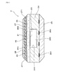
図1、図2に示すごとく、本例のガスセンサ1は、被測定ガスG中の特定ガス濃度を検出するセンサ素子2と、センサ素子2を内側に挿通して保持するハウジング13と、ハウジング13の軸方向先端側X1に配設された素子カバー3とを備えている。
センサ素子2の先端部201には、その内部に被測定ガスGを導入するためのガス導入部271が設けられている。
Example 1
Embodiments of the gas sensor will be described with reference to the drawings.
As shown in FIGS. 1 and 2, the
A
同図に示すごとく、素子カバー3は、センサ素子2の先端部201を覆うように配設されたインナカバー4と、インナカバー4の外側に配設されたアウタカバー5とを有する。アウタカバー5には、アウタカバー5内に被測定ガスGを導入するためのアウタ導入開口部52が設けられている。インナカバー4には、インナカバー4内に被測定ガスGを導入するためのインナ導入開口部42が設けられている。
センサ素子2のガス導入部271の軸方向中間位置C1は、インナカバー4のインナ導入開口部42の軸方向基端位置D1よりも軸方向基端側X2にある。
以下、本例のガスセンサ1についてさらに詳説する。
As shown in the figure, the
The intermediate position C1 in the axial direction of the
Hereinafter, the
図1に示すごとく、本例において、「軸方向先端側X1」とは、ガスセンサ1の軸方向Xの一方側であり、ガスセンサ1が被測定ガスGに晒される側をいう。また、「軸方向基端側X2」とは、その反対側をいう。
同図に示すごとく、ガスセンサ1において、板状のセンサ素子2は、第1絶縁碍子11の内側に挿通して保持されている。また、第1絶縁碍子11は、ハウジング13の内側に保持されている。
As shown in FIG. 1, in this example, the “axial tip side X <b> 1” is one side in the axial direction X of the
As shown in the figure, in the
図4に示すごとく、センサ素子2は、被測定ガスG(排ガス)中の特定ガス濃度(酸素濃度)に依存して電極(後述する被測定ガス側電極22、基準ガス側電極23)間を流れる限界電流をもとに内燃機関に供給される混合気の空燃比(A/F)を検出するA/Fセンサ素子である。
なお、図4は、センサ素子2の先端部201における軸方向Xに直交する断面を示したものである。
As shown in FIG. 4, the
FIG. 4 shows a cross section orthogonal to the axial direction X at the
同図に示すごとく、センサ素子2は、ジルコニアからなる酸素イオン伝導性の固体電解質体21を有する。板状の固体電解質体21の一方の面には、被測定ガスGを接触させる被測定ガス側電極22が設けられ、他方の面には、基準ガス(大気)を接触させる基準ガス側電極23が設けられている。
As shown in the figure, the
同図に示すごとく、固体電解質体21の基準ガス側電極23の側には、アルミナからなる基準ガス室形成層24が積層されている。基準ガス室形成層24には、溝部241が設けられており、この溝部241によって基準ガス室249が形成されている。基準ガス室249は、基準ガスを導入することができるよう構成されている。
As shown in the figure, a reference gas
基準ガス室形成層24における固体電解質体21とは反対側の面には、ヒータ基板25が積層されている。ヒータ基板25には、通電により発熱する発熱体(ヒータ)251が基準ガス室形成層24と対面するよう設けられている。発熱体251は、通電によって発熱させることにより、センサ素子2を活性温度まで加熱することができるよう構成されている。
A
同図に示すごとく、固体電解質体21の被測定ガス側電極22の側には、アルミナからなる絶縁層26が積層されている。絶縁層26は、開口部261を有する。また、絶縁層26における固体電解質体21とは反対側の面には、被測定ガスGを透過させるアルミナ多孔体からなる多孔質の拡散抵抗層27が積層されている。拡散抵抗層27の一部は、センサ素子2の外表面に露出しており、その露出した部分にガス導入部271が複数箇所形成されている。
As shown in the figure, an insulating
固体電解質体21と絶縁層26と拡散抵抗層27とにより覆われた場所には、被測定ガス室269が形成されている。被測定ガス室269は、拡散抵抗層27を透過した被測定ガスGを導入することができるよう構成されている。また、拡散抵抗層27における絶縁層26とは反対側の面には、アルミナからなる遮蔽層28が積層されている。
なお、図示を省略したが、センサ素子2の外表面には、拡散抵抗層27の露出した部分(ガス導入部271)を覆うように、被測定ガスG中の被毒成分を捕獲するための保護層等が設けられていてもよい。
A
Although not shown in the drawing, the outer surface of the
図1に示すごとく、ハウジング13の軸方向基端側X2には、センサ素子2の基端部202を覆うように第1基端側カバー14が固定されており、さらに第1基端側カバー14の軸方向基端側X2には、第2基端側カバー15が固定されている。第2基端側カバー15には、大気を導入する通気孔151が設けられている。また、第2基端側カバー15の基端側開口部は、ゴムブッシュからなる封止部材16によって閉塞されている。封止部材16には、外部に接続される複数のリード部材17が貫通配置されている。
As shown in FIG. 1, the first base
また、第1基端側カバー14の内部において、第1絶縁碍子11の軸方向基端側X2には、センサ素子2の基端部202を覆う第2絶縁碍子12が配設されている。第2絶縁碍子12には、リード部材17に接続された金属端子18が配設されている。金属端子18は、センサ素子2の電極端子に接触して電気的な導通を図っている。
In addition, a
同図に示すごとく、ハウジング13の先端側には、センサ素子2を保護するための素子カバー3が配設されている。素子カバー3は、センサ素子2の先端部201を覆うように配設された有底略円筒状のインナカバー4と、インナカバー4の外側に配設された有底略円筒状のアウタカバー5とを有する。インナカバー4は、ハウジング13の先端部に固定されている。また、アウタカバー5は、インナカバー4の基端部に固定されている。
As shown in the figure, an
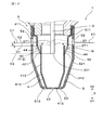
図2に示すごとく、アウタカバー5は、軸方向基端側X2から順に、軸方向Xに略同径のアウタ側面部511と、軸方向先端側X1に向かって縮径するテーパ状のアウタ縮径部512と、軸方向先端側X1を閉塞するアウタ底面部513とを有する。
アウタ側面部511には、複数のアウタ導入開口部52が周方向に所定の間隔で設けられている。アウタ導入開口部52の軸方向先端位置E1は、後述するインナカバー4のインナ導入開口部42の軸方向基端位置D1よりも軸方向基端側X2にある。また、アウタ底面部513には、アウタ排出開口部53が設けられている。
As shown in FIG. 2, the
In the outer
同図に示すごとく、インナカバー4は、軸方向基端側X2から順に、軸方向Xに略同径のインナ第1側面部411と、軸方向先端側X1に向かって縮径するテーパ状のインナ第1縮径部412と、軸方向Xに略同径のインナ第2側面部413と、軸方向先端側X1に向かって縮径するテーパ状のインナ第2縮径部414と、軸方向先端側X1を閉塞するインナ底面部415とを有する。
インナ底面部415は、アウタカバー5のアウタ底面部513と略同一平面上であって、アウタ底面部513のアウタ排出開口部53内に配置されている。
As shown in the figure, the
The inner
インナ第1縮径部412には、複数のインナ導入開口部42が周方向に所定の間隔で設けられている。複数のインナ導入開口部42は、軸方向Xに直交する平面において、ガスセンサ1の中心軸に対して同心円上に配置されている。すなわち、すべてのインナ導入開口部42は、軸方向位置が同じである。また、すべてのインナ導入開口部42の軸方向基端位置D1は、アウタカバー5のアウタ導入開口部52の軸方向先端位置E1よりも軸方向先端側X1にある。また、すべてのインナ導入開口部42は、ルーバー形状となっている。すなわち、インナ第1縮径部412には、インナ導入開口部42が設けられたそれぞれの内側位置において、被測定ガスGの流れを遮り、被測定ガスGが軸方向基端側X2へ流れるようにするルーバー部44が設けられている。また、インナ底面部415には、インナ排出開口部43が設けられている。
The inner first reduced
同図に示すごとく、センサ素子2のガス導入部271の軸方向中間位置C1は、インナカバー4のインナ導入開口部42の軸方向基端位置D1よりも軸方向基端側X2にある。本例では、すべてのインナ導入開口部42の軸方向基端位置D1よりも軸方向基端側X2にある。
また、センサ素子2の軸方向先端位置C3は、インナカバー4のインナ導入開口部42の軸方向基端位置D1よりも軸方向先端側X1にある。本例では、すべてのインナ導入開口部42の軸方向基端位置D1よりも軸方向先端側X1にある。
As shown in the figure, the axially intermediate position C1 of the
In addition, the axial tip position C3 of the
また、インナカバー4のインナ導入開口部42の軸方向基端位置D1からセンサ素子2のガス導入部271の軸方向中間位置C1までの軸方向距離aは、0mm<a≦3.0mmとしている。なお、軸方向距離aは、0mm<a≦3.0mmであることが好ましく、0.7mm≦a≦3.0mmであることがより好ましい。
The axial distance a from the axial base end position D1 of the inner introduction opening 42 of the
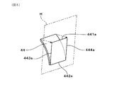
図3に示すごとく、ルーバー部44は、インナ導入開口部42の軸方向先端側X1の端部421からインナカバー4の内側に折り曲げられ、軸方向基端側X2に向かって形成されている。ルーバー部44は、略四角形状に形成されている。また、ルーバー部44は、インナカバー4の一部を金型等によって内側方向に押し出して形成されている。
また、インナカバー4におけるインナ導入開口部42よりも軸方向基端側X2の部分(本例のインナ第1側面部411)とルーバー部44との間の最短距離であるルーバー開度Aは、2.0mm以下に設定されている。
As shown in FIG. 3, the
Further, the louver opening A, which is the shortest distance between the portion (the inner first
図5、図6に示すごとく、ルーバー部44をインナ導入開口部42と同一平面(平面H)上に投影した場合、ルーバー部44は、先端側端縁441a、根元側端縁442a、一対の側端縁443a、444aを有する。一対の側端縁443a、444aは、ルーバー部44の根元側から先端側に向かうルーバー形成方向Vに対して略平行に、略直線状に形成されている。そして、ルーバー部44の根元側端縁442aと一対の側端縁443a、444aとの間の角度B1、B2が90度である。
なお、図5、図6は、インナカバー4からルーバー部44を取り出して示したものである。
As shown in FIGS. 5 and 6, when the
5 and 6 show the
図2に示すごとく、ルーバー部44の軸方向基端側X2の端部は、インナ導入開口部42の軸方向基端側X2の端部と、軸方向Xのほぼ同じ位置にある。そして、アウタカバー5とインナカバー4との間の空間からインナ導入開口部42を通過してインナカバー4内へ流れようとする被測定ガスGは、ルーバー部44によって遮られて、軸方向先端側X1へは流れない。この被測定ガスGの一部は、一対の側端縁443a、444aからインナカバー4内へ流れようとするものの、この被測定ガスGの多くは、ルーバー部44に沿って軸方向基端側X2へ流れる。
As shown in FIG. 2, the end of the
次に、本例のガスセンサ1における作用効果について説明する。
本例のガスセンサ1において、センサ素子2の先端部201には、その内部に被測定ガスGを導入するためのガス導入部271が設けられている。また、センサ素子2の先端部201を覆うインナカバー4には、インナカバー4内に被測定ガスGを導入するためのインナ導入開口部42が設けられている。そして、センサ素子2のガス導入部271の軸方向中間位置C1は、インナカバー4のインナ導入開口部42の軸方向基端位置D1よりも軸方向基端側X2にある。また、インナカバー4におけるインナ導入開口部42の内側位置には、インナ導入開口部42からインナカバー4内に流入する被測定ガスGが、軸方向基端側X2へ流れるようにするルーバー部44が設けられている。
Next, the effect in the
In the
これにより、図7に示すごとく、インナ導入開口部42からインナカバー4内へ流れようとする被測定ガスGの多くは、ルーバー部44によってインナカバー4内の軸方向基端側X2へ流れ込ませることができる。また、ガス導入部271の軸方向中間位置C1が、インナ導入開口部42の軸方向基端位置D1よりも軸方向基端側X2にあることにより、インナ導入開口部42からインナカバー4内に導入された被測定ガスGをできるだけ短距離で迅速にセンサ素子2のガス導入部271に到達させることができる。また、被測定ガスGを他のインナ導入開口部42から流れ込んだ被測定ガスGと混合させることなく、センサ素子2のガス導入部271に到達させることができる。そして、内燃機関の各気筒の被測定ガスGを順にセンサ素子2のガス導入部271に到達させ、センサ素子2のガス導入部271に到達するまでの間に各気筒の被測定ガスGが混合されることを抑制することができる。
As a result, as shown in FIG. 7, most of the gas G to be measured that flows from the inner introduction opening 42 into the
その結果、ガスセンサ1の応答性を高めることができ、内燃機関の気筒間インバランスの指標となるガスセンサ1の出力値(空燃比:A/F)の変化をより正確に把握することができる。そして、ガスセンサ1における内燃機関の気筒間インバランスの検出精度を向上させることができる。
As a result, the responsiveness of the
図8には、多気筒の内燃機関において、いずれかの気筒71aの空燃比が理論空燃比に対してリッチ側にあり、他の気筒71bの空燃比が理論空燃比に対してリーン側にあるときの排気管82における被測定ガスG(排気ガス)の流れを示す。同図に示すごとく、各気筒71a、71bからの排気は順次行われ、排気管82内のガスセンサ1には、リッチ側の被測定ガスG1とリーン側の被測定ガスG2とが順次到達すると考えられる。
図9には、ガスセンサ1によって測定される被測定ガスGのガス濃度の時間変化を示す。同図に示すごとく、ガスセンサ1においては、リッチ側の被測定ガスG1とリーン側の被測定ガスG2とが交互に測定されることになると考えられる。
In FIG. 8, in the multi-cylinder internal combustion engine, the air-fuel ratio of one of the
FIG. 9 shows the change over time in the gas concentration of the measurement gas G measured by the
そして、時間的に前後して排気され、インナカバー4内に前後して流入する被測定ガスGが混ざりにくい状態にあることにより、所定の時間間隔で到達すると考えられるリッチ側の被測定ガスG1とリーン側の被測定ガスG2とが混ざりにくくすることができる。
本例においては、ルーバー部44に沿って軸方向基端側X2へ流れる被測定ガスGが、センサ素子2のガス導入部271に到達するまでの距離を短くしている。これにより、時間的に前後して排気された被測定ガスGの混ざり合いを抑制し、ガスセンサ1における内燃機関の気筒間インバランスの検出精度を向上させることができると考えられる。
Then, the measurement gas G1 on the rich side, which is considered to arrive at a predetermined time interval, is in a state in which the measurement gas G exhausted back and forth in time and flows back and forth into the
In this example, the distance until the measured gas G flowing along the
また、本例において、センサ素子2の軸方向先端位置C3は、インナカバー4のインナ導入開口部42の軸方向基端位置D1よりも軸方向先端側X1にある。そのため、インナ導入開口部42からインナカバー4内に導入された被測定ガスGをより一層短距離で迅速にセンサ素子2のガス導入部271に到達させることができる。これにより、内燃機関の気筒間インバランスの検出精度、及び気筒間インバランスを検出する応答性をさらに高めることができる。
Further, in this example, the axial front end position C3 of the
また、ルーバー部44をインナ導入開口部42と同一平面(平面H)上に投影した場合、ルーバー部44の一対の側端縁443a、444aは、ルーバー形成方向Vに対して略平行に、略直線状に形成されている。
そのため、図7に示すごとく、被測定ガスGがルーバー部44の表面に沿って、ルーバー部44の根元側から先端側に向かって流れやすくなる。そして、被測定ガスGの一部がルーバー部44の側端部443、444から両側に漏れてインナカバー4内に流れ込むことを抑制することができる。つまり、ルーバー部44の先端部441を通過して流れ込む被測定ガスGの流量の割合をさらに高めることができる。
Further, when the
Therefore, as shown in FIG. 7, the gas to be measured G easily flows along the surface of the
また、インナカバー4におけるインナ導入開口部42よりも軸方向基端側X2の部分(インナ第1側面部411)とルーバー部44との間の最短距離であるルーバー開度Aは、2.0mm以下である。そのため、インナ導入開口部42からルーバー部44を介してインナカバー4内に流れ込む被測定ガスGの流量を適切に制御することができ、ガスセンサ1の応答性をより一層高めることができる。
Further, the louver opening A, which is the shortest distance between the portion (inner first side surface portion 411) closer to the axial base end side X2 than the inner introduction opening 42 in the
また、アウタカバー5のアウタ導入開口部52の軸方向先端位置E1は、インナカバー4のインナ導入開口部42の軸方向基端位置D1よりも軸方向基端側X2にある。
そのため、図7に示すごとく、アウタ導入開口部52からアウタカバー5内(アウタカバー5とインナカバー4との間)に導入された被測定ガスGは、軸方向先端側X1に向かって流れ、途中で向きを変えてインナ導入開口部42からインナカバー4内に流れ込む。このとき、被測定ガスGと共に流れる水滴Wは、被測定ガスGよりも質量が大きいため、その自重によってそのまま軸方向先端側X1に流れる。
Also, the axial front end position E1 of the outer introduction opening 52 of the
Therefore, as shown in FIG. 7, the gas G to be measured introduced into the outer cover 5 (between the
これにより、同図に示すごとく、被測定ガスGと水滴Wとをより分離しやすくなり、水滴Wがインナカバー4内に侵入することを防止する効果をより高めることができる。その結果、センサ素子2の被水及びそれに伴うセンサ素子2の割れを防止することができる。そして、耐被水性を向上させながら、ガスセンサ1の応答性、内燃機関の気筒間インバランスの検出精度を十分に確保することができる。なお、分離された水滴Wは、アウタカバー5のアウタ排出開口部53から外部に排出される。
Thereby, as shown in the figure, it becomes easier to separate the gas G to be measured and the water droplet W, and the effect of preventing the water droplet W from entering the
このように、本例によれば、内燃機関の気筒間インバランスの検出精度、及び気筒間インバランスを検出する応答性に優れたガスセンサ1を提供することができる。
As described above, according to this example, it is possible to provide the
なお、本例では、図5、図6に示すごとく、ルーバー部44をインナ導入開口部42と同一平面(平面H)上に投影した場合、ルーバー部44の一対の側端縁443a、444aは、ルーバー形成方向Vに対して略平行に、略直線状に形成されている。これ以外にも、例えば、図10に示すごとく、ルーバー部44の一対の側端縁443a、444aは、ルーバー形成方向Vに対して外側に傾斜して、略直線状に形成されていてもよい。すなわち、ルーバー部44の根元側端縁442aと一対の側端縁443a、444aとの間の角度B1、B2が90度を超えた角度(例えば、90度超え95度以下)であってもよい。
In this example, as shown in FIGS. 5 and 6, when the
上記構成の場合には、図11に示すごとく、被測定ガスGがルーバー部44の表面に沿って、ルーバー部44の根元側から先端側に向かってより一層流れやすくなる。そして、被測定ガスGの一部がルーバー部44の側端部443、444から両側に漏れてインナカバー4内に流れ込むことをさらに抑制することができる。つまり、ルーバー部44の先端部441を通過して流れ込む被測定ガスGの流量の割合をさらに高めることができる。これにより、内燃機関の気筒間インバランスの検出精度、及び気筒間インバランスを検出する応答性をより一層向上させることができる。
In the case of the above configuration, as shown in FIG. 11, the gas G to be measured is more likely to flow along the surface of the
(実施例2)
本例は、図12に示すごとく、センサ素子2のガス導入部271とインナカバー4のインナ導入開口部42との位置関係を変更した例である。
同図に示すごとく、センサ素子2のガス導入部271の軸方向先端位置C2は、インナカバー4のインナ導入開口部42の軸方向基端位置D1よりも軸方向基端側X2にある。本例では、ガス導入部271の軸方向先端位置C2は、すべてのインナ導入開口部42の軸方向基端位置D1よりも軸方向基端側X2にある。
その他の基本的な構成は、実施例1と同様である。また、実施例1と同様の構成については、同様の符号を付し、その説明を省略している。
(Example 2)
In this example, as shown in FIG. 12, the positional relationship between the
As shown in the figure, the axial front end position C2 of the
Other basic configurations are the same as those in the first embodiment. Moreover, about the structure similar to Example 1, the same code | symbol is attached | subjected and the description is abbreviate | omitted.
本例のインナカバー4におけるインナ導入開口部42の内側位置には、実施例1と同様に、インナ導入開口部42からインナカバー4内に流入する被測定ガスGが、軸方向基端側X2へ流れるようにするルーバー部44が設けられている。そして、インナ導入開口部42からインナカバー4内に流れる被測定ガスGの多くは、軸方向基端側X2へ流れる。そのため、ガス導入部271の軸方向先端位置C2を、インナ導入開口部42の軸方向基端位置D1よりも軸方向基端側X2にすることにより、ルーバー部44に沿って軸方向基端側X2へ流れる被測定ガスGが、より一層短距離で迅速にセンサ素子2のガス導入部271に到達するようにできる。これにより、内燃機関の気筒間インバランスの検出精度、及び気筒間インバランスを検出する応答性をさらに高めることができる。
その他の基本的な作用効果は、実施例1と同様である。
In the
Other basic functions and effects are the same as those of the first embodiment.
(実施例3)
本例は、ガスセンサについて、内燃機関の気筒間インバランスの検出精度を評価したものである。
本例では、インナカバーのインナ導入開口部の軸方向基端位置からセンサ素子のガス導入部の軸方向中間位置までの軸方向距離a(図2参照)が異なる複数のガスセンサを準備した。準備したガスセンサのその他の基本的な構成は、実施例1のガスセンサ(図1〜図4等参照)と同様である。
(Example 3)
In this example, the detection accuracy of the imbalance between cylinders of the internal combustion engine is evaluated for the gas sensor.
In this example, a plurality of gas sensors having different axial distances a (see FIG. 2) from the axial base end position of the inner introduction opening of the inner cover to the axial intermediate position of the gas introduction portion of the sensor element were prepared. The other basic structure of the prepared gas sensor is the same as that of the gas sensor of Example 1 (refer FIGS. 1-4).
次に、内燃機関の気筒間インバランスの検出精度の評価方法について説明する。
本例では、図13に示すごとく、4つの気筒(第1気筒811、第2気筒812、第3気筒813、第4気筒814)を有する直列4気筒型の内燃機関81を準備した。内燃機関81の各気筒811〜814は、それぞれ排気管82の排気枝部821に連通している。4つの排気枝部821は、その下流側において集合して排気管82の排気集合部822に連通している。そして、この排気管82の排気集合部822に、ガスセンサ89を取り付けた。
Next, a method for evaluating the detection accuracy of the inter-cylinder imbalance of the internal combustion engine will be described.
In this example, an in-line four-cylinder
次いで、内燃機関を所定の条件で運転させた。本例では、回転数を1600rpmに設定し、排気管内の単位断面積当たりのガス流量が20g/秒となるように調整した。そして、内燃機関の4つの気筒のうち、第2気筒の燃料噴射量を他の気筒に比べて過剰に増加させた。本例では、第2気筒の空燃比が理論空燃比に対してリッチ側に40%ずらした状態(燃料噴射量を40%増加した状態)となるように調整した。 Next, the internal combustion engine was operated under predetermined conditions. In this example, the rotational speed was set to 1600 rpm, and the gas flow rate per unit cross-sectional area in the exhaust pipe was adjusted to 20 g / second. Of the four cylinders of the internal combustion engine, the fuel injection amount of the second cylinder is excessively increased compared to the other cylinders. In this example, the air-fuel ratio of the second cylinder is adjusted so as to be shifted to the rich side by 40% with respect to the stoichiometric air-fuel ratio (a state where the fuel injection amount is increased by 40%).
そして、図14に示すごとく、時間経過ごとにガスセンサの出力値(空燃比:A/F)を取得した。
ここで、ガスセンサの出力値の波形は、内燃機関の1燃焼サイクルを1周期として変動する。内燃機関の1燃焼サイクルは、クランク角が0度の時に開始され、クランク角が720度のときに終了する。また、1燃焼サイクルの間、第1気筒、第3気筒、第4気筒、第2気筒の順に燃焼が行われる。また、各気筒では、燃焼の後に排気が行われるため、1燃焼サイクルの間、第2気筒、第1気筒、第3気筒、第4気筒の順に排気が行われる。したがって、理想的には、第2気筒、第1気筒、第3気筒、第4気筒の順に、各気筒から排出された排ガスがガスセンサのセンサ素子のガス導入部に到達する。
And as shown in FIG. 14, the output value (air-fuel ratio: A / F) of the gas sensor was acquired for every time passage.
Here, the waveform of the output value of the gas sensor varies with one combustion cycle of the internal combustion engine as one cycle. One combustion cycle of the internal combustion engine starts when the crank angle is 0 degree and ends when the crank angle is 720 degrees. During one combustion cycle, combustion is performed in the order of the first cylinder, the third cylinder, the fourth cylinder, and the second cylinder. Further, since exhaust is performed after combustion in each cylinder, exhaust is performed in the order of the second cylinder, the first cylinder, the third cylinder, and the fourth cylinder during one combustion cycle. Therefore, ideally, the exhaust gas discharged from each cylinder reaches the gas introduction part of the sensor element of the gas sensor in the order of the second cylinder, the first cylinder, the third cylinder, and the fourth cylinder.
次に、内燃機関の気筒間インバランスの検出精度の評価方法について説明する。
図14に示すごとく、取得したガスセンサの出力値(空燃比:A/F)の波形から、1燃焼サイクル中の波形の振幅P(最大値と最小値との差)をインバランス応答値として求めた。
本例では、軸方向距離aが異なるガスセンサに対して、それぞれ上述したインバランス応答値を求めた。そして、軸方向距離aが−1.5mmのガスセンサ(従来の仕様のガスセンサ)のインバランス応答値を基準(=100%)とし、その他のガスセンサのインバランス応答値比(%)を求めた。なお、インバランス応答値比が高いほうが内燃機関の気筒間インバランスの検出精度がより高いことを示す。
Next, a method for evaluating the detection accuracy of the inter-cylinder imbalance of the internal combustion engine will be described.
As shown in FIG. 14, the waveform amplitude P (difference between the maximum value and the minimum value) in one combustion cycle is obtained as an imbalance response value from the waveform of the acquired output value (air-fuel ratio: A / F) of the gas sensor. It was.
In this example, the above-described imbalance response values were obtained for gas sensors having different axial distances a. Then, the imbalance response value of the gas sensor having the axial distance a of −1.5 mm (conventional gas sensor) was used as a reference (= 100%), and the imbalance response value ratio (%) of the other gas sensors was obtained. It should be noted that a higher imbalance response value ratio indicates a higher detection accuracy of the inter-cylinder imbalance of the internal combustion engine.
図15に、内燃機関の気筒間インバランスの検出精度の評価結果を示す。同図の横軸は軸方向距離a(mm)、縦軸はインバランス応答値比(%)である。
なお、軸方向距離aが0mmの場合は、センサ素子のガス導入部の軸方向中間位置とインナカバーのインナ導入開口部の軸方向基端位置とが同じ位置であることを示す。また、軸方向距離aが0mm未満の場合は、センサ素子のガス導入部の軸方向中間位置がインナカバーのインナ導入開口部の軸方向基端位置よりも軸方向先端側にあることを示す。
FIG. 15 shows the evaluation result of the detection accuracy of the inter-cylinder imbalance of the internal combustion engine. In the figure, the horizontal axis represents the axial distance a (mm), and the vertical axis represents the imbalance response value ratio (%).
When the axial distance a is 0 mm, it indicates that the axial intermediate position of the gas introduction part of the sensor element and the axial base end position of the inner introduction opening part of the inner cover are the same position. Further, when the axial distance a is less than 0 mm, it indicates that the axial intermediate position of the gas introducing portion of the sensor element is closer to the distal end side in the axial direction than the axial proximal end position of the inner introducing opening of the inner cover.
同図から、軸方向距離aが0mmを超えると、すなわちセンサ素子のガス導入部の軸方向中間位置がインナカバーのインナ導入開口部の軸方向基端位置よりも軸方向基端側にあると、インバランス応答値比が高くなることがわかった。また、軸方向距離aが0.7mmあたりを超えると、インバランス応答値比がさらに高くなり、そのインバランス応答値比が安定していることがわかった。
一方、軸方向距離aが3.0mmあたりを超えると、インバランス応答値比が少し低くなることがわかった。
From this figure, when the axial distance a exceeds 0 mm, that is, the axial intermediate position of the gas introduction part of the sensor element is closer to the axial base end side than the axial base end position of the inner introduction opening of the inner cover. It was found that the imbalance response value ratio was high. Further, it was found that when the axial distance a exceeds about 0.7 mm, the imbalance response value ratio is further increased, and the imbalance response value ratio is stable.
On the other hand, it was found that the imbalance response value ratio slightly decreased when the axial distance a exceeded about 3.0 mm.
以上の結果から、センサ素子のガス導入部の軸方向中間位置がインナカバーのインナ導入開口部の軸方向基端位置よりも軸方向基端側にあることにより、ガスセンサの応答性を高めることができ、ガスセンサにおける内燃機関の気筒間インバランスの検出精度を向上させることができることがわかった。
また、このような効果を十分に得るためには、センサ素子のガス導入部の軸方向中間位置からインナカバーのインナ導入開口部の軸方向基端位置までの軸方向距離aを0.7mm以上とすることが好ましく、3.0mm以下とすることが好ましいことがわかった。
From the above results, the responsiveness of the gas sensor can be improved by the fact that the axial intermediate position of the gas introduction portion of the sensor element is closer to the axial proximal end side than the axial proximal end position of the inner introduction opening of the inner cover. It was found that the accuracy of detecting the imbalance between cylinders of the internal combustion engine in the gas sensor can be improved.
In order to obtain such an effect sufficiently, the axial distance a from the axial intermediate position of the gas introduction part of the sensor element to the axial base end position of the inner introduction opening of the inner cover is 0.7 mm or more. It was found that the thickness was preferably 3.0 mm or less.
1 ガスセンサ
13 ハウジング
2 センサ素子
201 先端部(センサ素子の先端部)
271 ガス導入部
3 素子カバー
4 インナカバー
42 インナ導入開口部
5 アウタカバー
52 アウタ導入開口部
C1 軸方向中間位置(ガス導入部の軸方向中間位置)
D1 軸方向基端位置(インナ導入開口部の軸方向基端位置)
X1 軸方向先端側
X2 軸方向基端側
DESCRIPTION OF
271
D1 axial base end position (axial base end position of the inner introduction opening)
X1 Axial distal end X2 Axis proximal end
Claims (6)
該センサ素子(2)を内側に挿通して保持するハウジング(13)と、
該ハウジング(13)の軸方向先端側(X1)に配設された素子カバー(3)とを備え、
上記センサ素子(2)の先端部(201)には、その内部に被測定ガスを導入するためのガス導入部(271)が設けられており、
上記素子カバー(3)は、上記センサ素子(2)の先端部(201)を覆うように配設されたインナカバー(4)と、該インナカバー(4)の外側に配設されたアウタカバー(5)とを有し、
該アウタカバー(5)には、該アウタカバー(5)内に被測定ガスを導入するためのアウタ導入開口部(52)が設けられており、
上記インナカバー(4)には、該インナカバー(4)内に被測定ガスを導入するためのインナ導入開口部(42)が設けられており、
上記センサ素子(2)の上記ガス導入部(271)の軸方向中間位置(C1)は、上記インナカバー(4)の上記インナ導入開口部(42)の軸方向基端位置(D1)よりも軸方向基端側(X2)にあることを特徴とするガスセンサ(1)。 A sensor element (2) for detecting a specific gas concentration in the gas to be measured;
A housing (13) for inserting and holding the sensor element (2) inside;
An element cover (3) disposed on the axially distal end side (X1) of the housing (13),
The tip (201) of the sensor element (2) is provided with a gas introduction part (271) for introducing a gas to be measured therein,
The element cover (3) includes an inner cover (4) disposed so as to cover the distal end portion (201) of the sensor element (2), and an outer cover (external cover (4) disposed outside the inner cover (4)). 5)
The outer cover (5) is provided with an outer introduction opening (52) for introducing a gas to be measured into the outer cover (5).
The inner cover (4) is provided with an inner introduction opening (42) for introducing a gas to be measured into the inner cover (4).
The axial intermediate position (C1) of the gas introduction part (271) of the sensor element (2) is more than the axial base end position (D1) of the inner introduction opening (42) of the inner cover (4). A gas sensor (1) characterized by being on the axially proximal end (X2).
Priority Applications (5)
| Application Number | Priority Date | Filing Date | Title |
|---|---|---|---|
| JP2013198541A JP5765394B2 (en) | 2012-11-20 | 2013-09-25 | Gas sensor |
| DE112013005545.7T DE112013005545T5 (en) | 2012-11-20 | 2013-11-18 | gas sensor |
| CN201380060519.2A CN104797931B (en) | 2012-11-20 | 2013-11-18 | Gas sensor |
| US14/646,137 US10393694B2 (en) | 2012-11-20 | 2013-11-18 | Gas sensor |
| PCT/JP2013/081017 WO2014080859A1 (en) | 2012-11-20 | 2013-11-18 | Gas sensor |
Applications Claiming Priority (3)
| Application Number | Priority Date | Filing Date | Title |
|---|---|---|---|
| JP2012254228 | 2012-11-20 | ||
| JP2012254228 | 2012-11-20 | ||
| JP2013198541A JP5765394B2 (en) | 2012-11-20 | 2013-09-25 | Gas sensor |
Publications (3)
| Publication Number | Publication Date |
|---|---|
| JP2014122877A true JP2014122877A (en) | 2014-07-03 |
| JP2014122877A5 JP2014122877A5 (en) | 2015-03-26 |
| JP5765394B2 JP5765394B2 (en) | 2015-08-19 |
Family
ID=50776042
Family Applications (1)
| Application Number | Title | Priority Date | Filing Date |
|---|---|---|---|
| JP2013198541A Active JP5765394B2 (en) | 2012-11-20 | 2013-09-25 | Gas sensor |
Country Status (5)
| Country | Link |
|---|---|
| US (1) | US10393694B2 (en) |
| JP (1) | JP5765394B2 (en) |
| CN (1) | CN104797931B (en) |
| DE (1) | DE112013005545T5 (en) |
| WO (1) | WO2014080859A1 (en) |
Cited By (3)
| Publication number | Priority date | Publication date | Assignee | Title |
|---|---|---|---|---|
| JP2016142683A (en) * | 2015-02-04 | 2016-08-08 | 日本特殊陶業株式会社 | Gas sensor |
| JP2017194285A (en) * | 2016-04-18 | 2017-10-26 | 株式会社デンソー | Gas sensor |
| JP2019207134A (en) * | 2018-05-29 | 2019-12-05 | 日本特殊陶業株式会社 | Gas sensor |
Families Citing this family (3)
| Publication number | Priority date | Publication date | Assignee | Title |
|---|---|---|---|---|
| JP6269348B2 (en) * | 2014-06-30 | 2018-01-31 | 株式会社デンソー | Gas sensor |
| JP6984356B2 (en) * | 2017-11-29 | 2021-12-17 | 株式会社デンソー | Sensor device |
| JP7151542B2 (en) * | 2019-02-21 | 2022-10-12 | 株式会社デンソー | sensor device |
Citations (6)
| Publication number | Priority date | Publication date | Assignee | Title |
|---|---|---|---|---|
| JP2005227179A (en) * | 2004-02-13 | 2005-08-25 | Denso Corp | Gas sensor |
| JP2007316051A (en) * | 2006-04-27 | 2007-12-06 | Denso Corp | Gas sensor |
| JP2008076211A (en) * | 2006-09-21 | 2008-04-03 | Denso Corp | Gas sensor |
| JP2009025076A (en) * | 2007-07-18 | 2009-02-05 | Denso Corp | Gas sensor |
| JP2012002805A (en) * | 2010-05-18 | 2012-01-05 | Ngk Insulators Ltd | Gas concentration detection sensor |
| JP2013142997A (en) * | 2012-01-11 | 2013-07-22 | Nk Works Kk | Image processing program and image processing apparatus |
Family Cites Families (29)
| Publication number | Priority date | Publication date | Assignee | Title |
|---|---|---|---|---|
| JPS6378265A (en) | 1986-09-20 | 1988-04-08 | Fujitsu Ltd | Process controlling system |
| JPH01146155A (en) | 1987-12-02 | 1989-06-08 | Victor Co Of Japan Ltd | Tape cassette loading device |
| JPH0635175Y2 (en) * | 1988-03-31 | 1994-09-14 | マツダ株式会社 | Semiconductor O ▲ Lower 2 ▼ Sensor |
| JP2641346B2 (en) | 1991-07-23 | 1997-08-13 | 日本碍子株式会社 | Oxygen sensor |
| JPH05272382A (en) | 1992-03-24 | 1993-10-19 | Nissan Motor Co Ltd | Air-fuel ratio control device for multiple cylinder engine |
| JPH11248671A (en) | 1998-02-26 | 1999-09-17 | Ngk Spark Plug Co Ltd | Gas sensor |
| US6346179B1 (en) | 1998-08-05 | 2002-02-12 | Ngk Spark Plug Co., Ltd. | Gas sensor |
| JP3531859B2 (en) * | 1998-09-28 | 2004-05-31 | 株式会社デンソー | Gas sensor |
| JP3510132B2 (en) | 1999-01-27 | 2004-03-22 | 株式会社日立製作所 | Engine control device |
| JP3829026B2 (en) | 1999-04-19 | 2006-10-04 | 日本碍子株式会社 | Gas sensor |
| JP4669638B2 (en) | 2001-07-31 | 2011-04-13 | 日本特殊陶業株式会社 | Gas sensor |
| US7660191B2 (en) * | 2005-07-12 | 2010-02-09 | Westerngeco L.L.C. | Methods and apparatus for acquisition of marine seismic data |
| JP2007101353A (en) | 2005-10-04 | 2007-04-19 | Denso Corp | Gas sensor |
| CN1959396A (en) * | 2005-11-04 | 2007-05-09 | 株式会社电装 | Gas sensor |
| CN100549688C (en) * | 2005-11-10 | 2009-10-14 | 株式会社电装 | Gas sensor |
| JP2007155697A (en) | 2005-11-10 | 2007-06-21 | Denso Corp | Gas sensor |
| JP2008058297A (en) | 2006-08-04 | 2008-03-13 | Ngk Spark Plug Co Ltd | Gas sensor |
| US7612620B2 (en) * | 2007-06-29 | 2009-11-03 | Micron Technology, Inc. | System and method for conditioning differential clock signals and integrated circuit load board using same |
| JP4445001B2 (en) | 2007-11-21 | 2010-04-07 | 株式会社日本自動車部品総合研究所 | Exhaust purification device |
| JP4762338B2 (en) * | 2008-12-22 | 2011-08-31 | 株式会社日本自動車部品総合研究所 | Gas sensor element and gas sensor provided with the same |
| JP5207409B2 (en) * | 2009-01-19 | 2013-06-12 | 日本特殊陶業株式会社 | Sensor defect detection method |
| US8513961B2 (en) * | 2009-01-19 | 2013-08-20 | Ngk Spark Plug Co., Ltd. | Detection method for defect of sensor |
| JP5171896B2 (en) | 2010-07-15 | 2013-03-27 | 日本特殊陶業株式会社 | Gas sensor |
| JP5416686B2 (en) | 2010-12-13 | 2014-02-12 | 日本特殊陶業株式会社 | Multi gas sensor |
| CN102565152B (en) * | 2010-12-17 | 2015-05-20 | 株式会社电装 | Gas sensor |
| JP5408456B2 (en) | 2011-03-31 | 2014-02-05 | トヨタ自動車株式会社 | Gas sensor |
| JP5747801B2 (en) | 2011-12-01 | 2015-07-15 | 株式会社デンソー | Multilayer ceramic exhaust gas sensor element, exhaust gas sensor using the same, and method of manufacturing multilayer ceramic exhaust gas sensor element |
| JP5240384B2 (en) | 2012-06-22 | 2013-07-17 | トヨタ自動車株式会社 | Control device for multi-cylinder internal combustion engine |
| JP5884803B2 (en) | 2012-11-20 | 2016-03-15 | 株式会社デンソー | Gas sensor |
-
2013
- 2013-09-25 JP JP2013198541A patent/JP5765394B2/en active Active
- 2013-11-18 WO PCT/JP2013/081017 patent/WO2014080859A1/en active Application Filing
- 2013-11-18 CN CN201380060519.2A patent/CN104797931B/en active Active
- 2013-11-18 US US14/646,137 patent/US10393694B2/en active Active
- 2013-11-18 DE DE112013005545.7T patent/DE112013005545T5/en active Pending
Patent Citations (6)
| Publication number | Priority date | Publication date | Assignee | Title |
|---|---|---|---|---|
| JP2005227179A (en) * | 2004-02-13 | 2005-08-25 | Denso Corp | Gas sensor |
| JP2007316051A (en) * | 2006-04-27 | 2007-12-06 | Denso Corp | Gas sensor |
| JP2008076211A (en) * | 2006-09-21 | 2008-04-03 | Denso Corp | Gas sensor |
| JP2009025076A (en) * | 2007-07-18 | 2009-02-05 | Denso Corp | Gas sensor |
| JP2012002805A (en) * | 2010-05-18 | 2012-01-05 | Ngk Insulators Ltd | Gas concentration detection sensor |
| JP2013142997A (en) * | 2012-01-11 | 2013-07-22 | Nk Works Kk | Image processing program and image processing apparatus |
Cited By (5)
| Publication number | Priority date | Publication date | Assignee | Title |
|---|---|---|---|---|
| JP2016142683A (en) * | 2015-02-04 | 2016-08-08 | 日本特殊陶業株式会社 | Gas sensor |
| JP2017194285A (en) * | 2016-04-18 | 2017-10-26 | 株式会社デンソー | Gas sensor |
| WO2017183491A1 (en) * | 2016-04-18 | 2017-10-26 | 株式会社デンソー | Gas sensor |
| JP2019207134A (en) * | 2018-05-29 | 2019-12-05 | 日本特殊陶業株式会社 | Gas sensor |
| JP7008577B2 (en) | 2018-05-29 | 2022-01-25 | 日本特殊陶業株式会社 | Gas sensor |
Also Published As
| Publication number | Publication date |
|---|---|
| DE112013005545T5 (en) | 2015-07-30 |
| US20150300979A1 (en) | 2015-10-22 |
| US10393694B2 (en) | 2019-08-27 |
| WO2014080859A1 (en) | 2014-05-30 |
| JP5765394B2 (en) | 2015-08-19 |
| CN104797931B (en) | 2018-01-19 |
| CN104797931A (en) | 2015-07-22 |
Similar Documents
| Publication | Publication Date | Title |
|---|---|---|
| JP5884803B2 (en) | Gas sensor | |
| JP5765394B2 (en) | Gas sensor | |
| JP4131242B2 (en) | Gas sensor | |
| JP6741128B2 (en) | Gas sensor | |
| US10514356B2 (en) | Gas sensor | |
| JP2000171429A (en) | Gas sensor | |
| JP6909706B2 (en) | Gas sensor | |
| JP2013238556A (en) | Gas sensor | |
| JP2009025076A (en) | Gas sensor | |
| US10866207B2 (en) | Exhaust gas sensor | |
| CN108351322B (en) | Gas sensor | |
| WO2015076194A1 (en) | Oxygen sensor element | |
| JP2009145268A (en) | Gas sensor | |
| JP6233207B2 (en) | Gas sensor | |
| US20080142364A1 (en) | Gas sensor element designed to minimize direct exposure to water | |
| US11604160B2 (en) | Gas sensor | |
| JP6623963B2 (en) | Gas sensor | |
| JP6458364B2 (en) | Gas sensor | |
| WO2017047511A1 (en) | Gas sensor | |
| JP6535593B2 (en) | Gas sensor | |
| WO2017061313A1 (en) | Gas sensor | |
| JP4853461B2 (en) | Gas sensor | |
| JP2009042052A (en) | Gas sensor | |
| JP2009042053A (en) | Gas sensor |
Legal Events
| Date | Code | Title | Description |
|---|---|---|---|
| A621 | Written request for application examination |
Free format text: JAPANESE INTERMEDIATE CODE: A621 Effective date: 20140522 |
|
| A521 | Request for written amendment filed |
Free format text: JAPANESE INTERMEDIATE CODE: A523 Effective date: 20150206 |
|
| TRDD | Decision of grant or rejection written | ||
| A01 | Written decision to grant a patent or to grant a registration (utility model) |
Free format text: JAPANESE INTERMEDIATE CODE: A01 Effective date: 20150519 |
|
| A61 | First payment of annual fees (during grant procedure) |
Free format text: JAPANESE INTERMEDIATE CODE: A61 Effective date: 20150601 |
|
| R151 | Written notification of patent or utility model registration |
Ref document number: 5765394 Country of ref document: JP Free format text: JAPANESE INTERMEDIATE CODE: R151 |
|
| R250 | Receipt of annual fees |
Free format text: JAPANESE INTERMEDIATE CODE: R250 |
|
| R250 | Receipt of annual fees |
Free format text: JAPANESE INTERMEDIATE CODE: R250 |
|
| R157 | Certificate of patent or utility model (correction) |
Free format text: JAPANESE INTERMEDIATE CODE: R157 |
|
| R250 | Receipt of annual fees |
Free format text: JAPANESE INTERMEDIATE CODE: R250 |
|
| R250 | Receipt of annual fees |
Free format text: JAPANESE INTERMEDIATE CODE: R250 |
|
| R250 | Receipt of annual fees |
Free format text: JAPANESE INTERMEDIATE CODE: R250 |
|
| R250 | Receipt of annual fees |
Free format text: JAPANESE INTERMEDIATE CODE: R250 |